1 Introduction
Aircraft manufacturers estimate that as much as a 5 % reduction in fuel consumption is realistically achievable by extending the laminar boundary layer, and will lead to improved profit margins for operators as well as reduced environmental impact due to lower emissions. However, designing a robust laminar flow wing requires a deep understanding of the physics and mechanisms involved in boundary layer transition, a process known to be multifaceted and sensitive to environmental conditions (Saric, Reed & White Reference Saric, Reed and White2003). The development of robust predictive tools which incorporate the impact of real world environmental and small-scale surface geometrical uncertainties in the transition modelling process constitutes a major limitation in current methods.
In low disturbance atmospheric flight environments, transition is dominated by linear modal growth, and particularly in the case of unswept subsonic wings by a single instability of viscous nature denoted Tollmien–Schlichting (T–S) wave or first-mode instability. The generation of these disturbances in a laminar boundary layer, i.e. receptivity, arises as a consequence of a resonance mechanism involving conversion of long wavelength free-stream acoustic disturbances into T–S waves; see the seminal works of Goldstein (Reference Goldstein1983, Reference Goldstein1985) and Ruban (Reference Ruban and Kozlov1985). The length-scale reduction mechanism occurs in non-parallel flow regions, i.e. in regions of rapid boundary layer development, in the presence of surface features such as roughness or abrupt changes in curvature, among others. Crucially, the myriad paths to the onset of turbulence are intimately governed by and highly susceptible to changes in environmental conditions. This is one of the main reasons why recent research efforts have focused on receptivity.
Following the disturbance birth process, transition to turbulence undergoes the stages of linear modal growth, nonlinear development through harmonic modes, formation of secondary instabilities and a final complex breakdown process. There is an abundance of literature concerned with the linear growth of primary instabilities. We highlight the reviews of Mack (Reference Mack1984), Arnal & Casalis (Reference Arnal and Casalis2000) and Saric et al. (Reference Saric, Reed and White2003) as well as those of Kachanov (Reference Kachanov1994) and Hosseinverdi & Fasel (Reference Hosseinverdi and Fasel2019) on the nonlinear breakdown stages. Linear modal growth is modelled adequately through the parabolised stability equations (PSE), which today comprise the high-fidelity physics model (Bertolotti, Herbert & Spalart Reference Bertolotti, Herbert and Spalart1992; Herbert Reference Herbert1997).
The triple-deck asymptotic works of Goldstein (Reference Goldstein1985) and Ruban (Reference Ruban and Kozlov1985) underpin the guiding strategy in receptivity modelling. Choudhari & Streett (Reference Choudhari and Streett1992) and Crouch (Reference Crouch1992a ,Reference Crouch b ) used the essential ideas from the original asymptotic frameworks to develop a local, quasi-parallel flow, finite Reynolds number theory (FRNT) for localised and distributed surface roughness which was instrumental in experimental validations (Wiegel & Wlezien Reference Wiegel and Wlezien1993; Saric Reference Saric1994). Crouch & Spalart (Reference Crouch and Spalart1995) performed direct numerical simulations (DNS) while Streett (Reference Streett1998) proposed the use of the harmonic linear Navier–Stokes equations. Zhigulev & Fedorov (Reference Zhigulev and Fedorov1987) and Nayfeh & Ashour (Reference Nayfeh and Ashour1994) were among the first to use adjoint solutions to determine the amplitude of boundary layer instabilities. However, it was Hill (Reference Hill1995) who first provided a complete description of the properties of linear adjoint systems to the study of acoustic receptivity. Hill’s work was largely based on the work of Salwen & Grosch (Reference Salwen and Grosch1981), who established the bi-orthogonality relation between the eigensolutions of the Orr–Sommerfeld (O–S) equation and those of the adjoint system. In practice, this means the adjoint solution can be used to filter out the amplitude of a particular mode of interest from a complete flow solution. Advances for two- and three-dimensional disturbances in compressible boundary layers were made by Tumin & Fedorov (Reference Tumin and Fedorov1983) and Tumin (Reference Tumin2007) respectively. Airiau (Reference Airiau2000) and Dobrinsky (Reference Dobrinsky2003) extended Hill’s theory within the incompressible PSE context; Pralits et al. (Reference Pralits, Airiau, Hanifi and Henningson2000) derived the analogous compressible flow equations. Dobrinsky (Reference Dobrinsky2003) also investigated receptivity with the adjoint incompressible harmonic linearised Navier–Stokes (AHLNS) equations, an equation set that was later used to study incompressible stationary cross-flow instabilities by Carpenter et al. (Reference Carpenter, Choudhari, Li, Streett and Chang2010) and Tempelmann, Hanifi & Henningson (Reference Tempelmann, Hanifi and Henningson2012); Thomas, Mughal & Ashworth (Reference Thomas, Mughal and Ashworth2017) formulated and analysed the analogous compressible flow problem. An optimisation-based, non-modal approach (Schmid Reference Schmid2007) and a multiple-scales approach (Zuccher & Luchini Reference Zuccher and Luchini2014) have also been proposed. The reader is directed to Saric, Reed & Kerschen (Reference Saric, Reed and Kerschen2002) and Reed & Saric (Reference Reed and Saric2015) for detailed reviews of investigations carried out in the field of receptivity. From now on, we will mainly focus on the specificities of the acoustic receptivity problem in subsonic flow conditions.
Subsonic compressible flow conditions, the focus of this paper, have not merited as much attention as incompressible, supersonic and hypersonic flows, despite being fundamentally important for commercial aircraft wing design. Mack (Reference Mack1984) thoroughly reviewed the stability characteristics of a flat plate compressible boundary layer. The dominant instabilities in an incompressible Blasius flow are known to be two-dimensional (2-D) and of viscous type. Conversely, oblique three-dimensional (3-D) viscous instabilities are known to be more receptive to external disturbances. In subsonic and supersonic flows the dominant instability is the so-called viscous first mode, being most unstable for increasingly oblique angles for higher-speed flows (El-Hady Reference El-Hady1991). This scenario remains valid up to Mach numbers of approximately 3–4, after which the 2-D inviscid second mode becomes the dominant unstable mode. The multiple-scales approach was used by El-Hady (Reference El-Hady1991) while Bertolotti (Reference Bertolotti1991) used the PSE to account for non-parallel flow effects and concluded that the Mach number weakly influences this up to moderate supersonic flow speeds. Instead, it is the obliqueness of the wave that directly correlates with an increase in non-parallel effects, an important conclusion to take into account given the 3-D nature of the dominant modes.
In the field of receptivity, we highlight the work of Ruban (Reference Ruban and Kozlov1985), whose triple-deck-based asymptotic theory is valid for subsonic flows. Recently, this theoretical framework was extended to the transonic regime by Ruban, Bernots & Kravtsova (Reference Ruban, Bernots and Kravtsova2016). De Tullio & Ruban (Reference De Tullio and Ruban2015) (hereafter TR) compared the asymptotic approach with DNS simulations up to Mach number 0.8 for roughness-induced acoustic receptivity as well as for a vibrating ribbon placed on a flat plate. Choudhari (Reference Choudhari1994) studied the influence of Mach number and acoustic wave angle of incidence on localised receptivity due to surface temperature variations and wall suction by extending FRNT to compressible flows. The author used the forced compressible linear stability equations to account for reflection and refraction of the acoustic waves on the boundary layer (Mack Reference Mack1984) and proceeded to establish a comparison with the asymptotic prediction of Ruban (Reference Ruban and Kozlov1985). It was found that unsteady pressure variations across the boundary layer could be neglected when the free-stream Mach number was low or for shallow acoustic wave incidence, although it is unclear to what extent the asymptotic prediction is representative of the full modelling capabilities of the linearised unsteady boundary layer equations (LUBLE). Duck (Reference Duck1990) also studied the compressible Stokes layer, having derived high Strouhal number asymptotic solutions of the LUBLE. He restricted the study of acoustic wave reflections to the inviscid limit of the linear stability equations, with solutions thus failing to respect the no-slip boundary conditions. More recently, Bernots (Reference Bernots2014) studied oblique acoustic waves travelling upstream in transonic flows within triple-deck theory.
This paper is concerned with addressing the central issue of developing a high-fidelity, efficient and numerically robust acoustic receptivity model able to account for uncertainties in the external disturbance fields. In an earlier paper, in the context of incompressible flow, Raposo, Mughal & Ashworth (Reference Raposo, Mughal and Ashworth2018a ) (hereafter RMA) developed a receptivity framework based on Monte Carlo simulations to incorporate uncertainties due to randomly distributed surface roughness fields interacting with acoustic noise. The uncertainty quantification technique was built upon high-fidelity solutions of the harmonic linear Navier–Stokes (HLNS) equations (Mughal & Ashworth Reference Mughal and Ashworth2013). The acoustic receptivity model in this paper extends the incompressible work of RMA to the compressible regime in addition to developing the analogous adjoint form enabling faster uncertainty quantification analyses. Following Goldstein (Reference Goldstein1985) and Ruban (Reference Ruban and Kozlov1985), four sub-problems are solved in order to determine receptivity amplitudes. An additional two adjoint sub-problems need to be solved in order to compute the sensitivity functions.
The basic flow and the boundary layer acoustic signature are modelled with the unsteady compressible boundary layer equations. We show that the high Strouhal number behaviour of the compressible Stokes layer is not in agreement with the asymptotic solutions presented by Duck (Reference Duck1990) and proceed to re-derive them for an acoustic wave incident at an angle. Previous works in the literature (Goldstein Reference Goldstein1985; Choudhari & Streett Reference Choudhari and Streett1992; Crouch Reference Crouch1992a ; Airiau Reference Airiau2000) have often relied on the incompressible asymptotic form of the Stokes layer for receptivity calculations, with the notable exceptions of Choudhari (Reference Choudhari1994) and the DNS simulations of De Tullio & Ruban (Reference De Tullio and Ruban2015). In this study we rely on numerical solutions of the LUBLE, ensuring modelling of finite Strouhal number effects.
The steady mean-flow distortion induced by a wall inhomogeneity and the primary linear instability are modelled with the HLNS equations, whereas the adjoint fields are governed by the AHLNS equations. The discretised (A)HLNS equations, being elliptic in nature, ultimately require the solution of a large system of linear equations. The approach taken here is based on an efficient lower–upper (LU) decomposition and subsequent forward–backward substitution (see RMA for details). Current computational hardware makes this direct solution approach feasible, with high resolution numerical solutions on a stand-alone workstation possible in under fifteen minutes. Therefore the pursuit of this approach is in line with the need for high-fidelity receptivity models that can be used for systematic exploration of the vast parameter space in an efficient and optimal manner. One could argue, however, that the PSE constitute a more suitable alternative to the HLNS equations due to their near-parabolic character and proven validity in many contexts as a reduced-order model. Notwithstanding, the HLNS present several advantages: (i) they capture the near-field and spatial transient growth in the region of interaction; (ii) they remain valid in geometries of interest in aeronautical applications, specifically in the presence of gaps such as the wing-box junction; in such cases the strong localised flow gradients invalidate the PSE and thus the HLNS can be used instead to predict instability growth; (iii) the HLNS accommodate extensions to weakly nonlinear receptivity analyses for larger wall-disturbance amplitudes. Lastly, the proposed approach should also vastly outperform DNS while maintaining similar accuracy.
Assessing likely transition scenarios in compressible flows with an amplitude-based criterion requires quantifying receptivity amplitudes for a large parameter space. The characterisation of acoustic receptivity in subsonic and transonic flow conditions is currently very limited. In this work we formulate the fully compressible adjoint problem based on the HLNS equations for three different types of wall perturbation mechanisms – localised surface roughness, suction and heating. We use the FRNT results of Choudhari (Reference Choudhari1994) and DNS solutions of TR as benchmarks to validate the correctness of the overall modelling by comparing receptivity amplitudes and efficiency functions. Moreover, we propose an alternative formulation of the adjoint methodology of Hill (Reference Hill1995) that is suitable for predicting sensitivity to the acoustic wave angle of incidence. We study the influence of this parameter on receptivity and assess the validity and accuracy of asymptotic theory and of the numerical LUBLE-based approach.
The remainder of this paper is structured as follows. In § 2 we formulate the adjoint receptivity problem and present the governing equations for each of the aforementioned six sub-problems that require solving to determine receptivity amplitudes. In addition, we derive high Strouhal number composite asymptotic solutions of the acoustic field based on the LUBLE. This section is concluded with the formulation of the fully compressible adjoint problem. In § 3 we briefly describe the numerical methods and procedures put in place to obtain solutions. Section 4 starts with a validation exercise of the numerical and analytical Stokes layer solutions. We then proceed to validate the full receptivity model in the presence of surface roughness, suction and heating. Lastly, we conduct a parametric study to determine the influence of frequency, spanwise wavenumber and free-stream Mach number on the efficiency function.
2 Problem formulation
We consider a 2-D compressible laminar boundary layer growing on the upper surface of a semi-infinite flat plate immersed in a subsonic uniform flow. Three different types of localised wall perturbations are considered – roughness elements, suction slots and wall heating. Our analysis quantifies the amplitude of instability waves resulting from the interaction of one wall perturbation mechanism with an acoustic wave incident at an angle with the flat plate direction.
2.1 Flow expansion
The total flow is modelled by the full compressible Navier–Stokes equations. The acoustic wave streamwise velocity amplitude
 $u_{a,\infty }^{\ast }$
is considered to be small with respect to the free-stream velocity
 $\bar{U}_{\infty }$
, whereas the maximum amplitude of the wall perturbation
 $a_{w}^{\ast }$
is small compared to the reference scale
 $l_{w}^{\ast }$
. The definitions of
 $a_{w}^{\ast }$
and
 $l_{w}^{\ast }$
depend on the wall perturbation mechanism: (i) for surface roughness,
 $a_{w}^{\ast }=h^{\ast }$
is the roughness height and
 $l_{w}^{\ast }=L$
is the flat plate chord; (ii) for a suction slot,
 $a_{w}^{\ast }=v_{s}^{\ast }$
is the wall-normal suction velocity and
 $l_{w}^{\ast }=\bar{U}_{\infty }$
; (iii) for a heating strip,
 $a_{w}^{\ast }=\unicode[STIX]{x1D703}_{h}^{\ast }$
is the wall temperature differential and
 $l_{w}^{\ast }=\bar{T}_{\infty }$
is the far-field temperature. Thus we define two small parameters
 $\unicode[STIX]{x1D700}_{a}=u_{a,\infty }^{\ast }(\unicode[STIX]{x1D6E9}=0)/\bar{U}_{\infty }\ll 1$
and
 $\unicode[STIX]{x1D700}_{w}^{(j)}=a_{w}^{\ast }/l_{w}^{\ast }\ll 1$
, and introduce a double-parameter expansion of all flow quantities (Ruban Reference Ruban and Kozlov1985)
 $$\begin{eqnarray}\boldsymbol{q}(x,y,z,t)=\bar{\boldsymbol{q}}(x,y)+\unicode[STIX]{x1D700}_{w}^{(j)}\boldsymbol{q}_{w}(x,y)\text{e}^{\text{i}\unicode[STIX]{x1D6FD}z}+\unicode[STIX]{x1D700}_{a}\boldsymbol{q}_{a}(x,y)\text{e}^{-\text{i}\unicode[STIX]{x1D714}t}+\unicode[STIX]{x1D700}_{w}^{(j)}\unicode[STIX]{x1D700}_{a}\boldsymbol{q}_{b}(x,y)\text{e}^{\text{i}(-\unicode[STIX]{x1D714}t+\unicode[STIX]{x1D6FD}z)}+\cdots \,,\end{eqnarray}$$
where the index
 $j=1{-}3$
indicates the type of wall perturbation in the order that they were presented. A Cartesian frame of reference is positioned at the leading edge of the flat plate. The
 $x$
-axis is aligned with the streamwise direction. The fluid flow velocity component in this direction is denoted
 $u$
. In similar fashion, the
 $y$
-axis and
 $z$
-axis are aligned with the wall-normal and spanwise directions, and the velocity components are denoted
 $v$
and
 $w$
respectively. In addition to the velocity components, the vector
 $\boldsymbol{q}=[u,v,w,p,\unicode[STIX]{x1D70C},T]^{\text{T}}$
also contains the fluid flow pressure
 $p$
, density
 $\unicode[STIX]{x1D70C}$
and temperature
 $T$
. Time is denoted
 $t$
. The double-parameter expansion is truncated at order
 $\mathit{O}(\unicode[STIX]{x1D700}_{w}\unicode[STIX]{x1D700}_{a})$
, consisting of four terms: (i) the 2-D base flow denoted by an over-bar; (ii) a small steady component induced by a wall perturbation and denoted by the subscript
 $w$
; a single harmonic of spanwise wavenumber
 $\unicode[STIX]{x1D6FD}$
is considered; (iii) the acoustically driven flow of frequency
 $\unicode[STIX]{x1D714}$
denoted by the subscript
 $a$
; the 2-D free-stream acoustic wave is incident at an angle
 $\unicode[STIX]{x1D6E9}$
, where
 $\unicode[STIX]{x1D6E9}=0$
corresponds to a downstream travelling wave and
 $\unicode[STIX]{x1D6E9}=\unicode[STIX]{x03C0}$
corresponds to an upstream travelling wave; (iv) a small unsteady term arising from the bilinear interaction of the flow fields of order
 $\mathit{O}(\unicode[STIX]{x1D700}_{w})$
and
 $\mathit{O}(\unicode[STIX]{x1D700}_{a})$
; this component is denoted with the subscript
 $b$
and models the instability emerging from the receptivity process. This flow expansion captures the different components of the total flow to first order.
Flow and material quantities are made non-dimensional as follows
 $$\begin{eqnarray}\left.\begin{array}{@{}c@{}}x={\displaystyle \frac{x^{\ast }}{L}},\quad y={\displaystyle \frac{y^{\ast }}{L}},\quad z={\displaystyle \frac{z^{\ast }}{L}},\quad t={\displaystyle \frac{t^{\ast }\bar{U}_{\infty }}{L}},\quad u={\displaystyle \frac{u^{\ast }}{\bar{U}_{\infty }}},\quad v={\displaystyle \frac{v^{\ast }}{\bar{U}_{\infty }}},\\ w={\displaystyle \frac{w^{\ast }}{\bar{U}_{\infty }}},\quad p={\displaystyle \frac{p^{\ast }}{\bar{\unicode[STIX]{x1D70C}}_{\infty }\bar{U}_{\infty }^{2}}},\quad \unicode[STIX]{x1D70C}={\displaystyle \frac{\unicode[STIX]{x1D70C}^{\ast }}{\bar{\unicode[STIX]{x1D70C}}_{\infty }}},\quad T={\displaystyle \frac{T^{\ast }}{\bar{T}_{\infty }}},\quad \unicode[STIX]{x1D707}={\displaystyle \frac{\unicode[STIX]{x1D707}^{\ast }}{\bar{\unicode[STIX]{x1D707}}_{\infty }}},\end{array}\right\}\end{eqnarray}$$
where we have introduced the dynamic viscosity
 $\unicode[STIX]{x1D707}$
. Dimensional quantities are represented with a
 $\ast$
superscript. The reference quantities are the chord of the flat plate
 $L$
and the far-field flow quantities denoted by the subscript
 $\infty$
.
2.2 Unsteady compressible boundary layer
The governing equations are approximated by the unsteady boundary layer equations (see, for example, Duck Reference Duck1990) which suitably model the base flow and the acoustically driven flow to first order in a thin viscous wall layer (Ackerberg & Phillips Reference Ackerberg and Phillips1972). The underlying assumptions are high Reynolds number flow and long acoustic wavelength compared to boundary layer thickness. As opposed to the full Navier–Stokes equations, this system of equations is an attractive choice of physical model because of its parabolic character, allowing for an efficient streamwise marching numerical procedure.
2.2.1 Steady base flow
Let us denote
 $\bar{\boldsymbol{q}}=[\bar{U},\bar{V},\bar{W},\bar{P},\bar{\unicode[STIX]{x1D70C}},\bar{T}]^{\text{T}}$
the base flow quantities. We restrict our attention to 2-D flows, i.e.
 $\bar{W}=0$
. We introduce the generalised Howarth–Dorodnitsyn transformation (Moore Reference Moore1951; Stewartson Reference Stewartson1951)
 $$\begin{eqnarray}\unicode[STIX]{x1D702}=\left({\displaystyle \frac{\bar{U}_{e}^{\ast }}{\bar{\unicode[STIX]{x1D707}}_{e}^{\ast }\bar{\unicode[STIX]{x1D70C}}_{e}^{\ast }x^{\ast }}}\right)^{1/2}\int _{0}^{y^{\ast }}\bar{\unicode[STIX]{x1D70C}}^{\ast }\,\text{d}s,\end{eqnarray}$$
and the streamfunction
 $$\begin{eqnarray}\unicode[STIX]{x1D713}=(\bar{\unicode[STIX]{x1D70C}}_{e}^{\ast }\bar{\unicode[STIX]{x1D707}}_{e}^{\ast }\bar{U}_{e}^{\ast }x^{\ast })^{1/2}F(\unicode[STIX]{x1D702},x^{\ast }),\end{eqnarray}$$
with
 $$\begin{eqnarray}F_{\unicode[STIX]{x1D702}}={\displaystyle \frac{\bar{U}^{\ast }}{\bar{U}_{e}^{\ast }}},\quad S={\displaystyle \frac{\bar{T}^{\ast }}{\bar{T}_{e}^{\ast }}},\end{eqnarray}$$
where the subscript ‘
 $e$
’ denotes boundary layer edge quantities. For the purposes of this subsection we consider that all flow and material quantities are made non-dimensional using boundary layer edge quantities instead of the far-field quantities used in (2.2). The steady boundary layer equations are then simplified using (2.3)–(2.5), yielding
 $$\begin{eqnarray}\displaystyle & \displaystyle {\displaystyle \frac{\unicode[STIX]{x2202}(\unicode[STIX]{x1D719}F_{\unicode[STIX]{x1D702}\unicode[STIX]{x1D702}})}{\unicode[STIX]{x2202}\unicode[STIX]{x1D702}}}+cF_{\unicode[STIX]{x1D702}\unicode[STIX]{x1D702}}F+m_{1}(S-F_{\unicode[STIX]{x1D702}}^{2})=x(F_{\unicode[STIX]{x1D702}}F_{\unicode[STIX]{x1D702}x}-F_{\unicode[STIX]{x1D702}\unicode[STIX]{x1D702}}F_{x}), & \displaystyle\end{eqnarray}$$
 $$\begin{eqnarray}\displaystyle & \displaystyle {\displaystyle \frac{1}{\unicode[STIX]{x1D70E}}}{\displaystyle \frac{\unicode[STIX]{x2202}(\unicode[STIX]{x1D719}S_{\unicode[STIX]{x1D702}})}{\unicode[STIX]{x2202}\unicode[STIX]{x1D702}}}+cFS_{\unicode[STIX]{x1D702}}+\unicode[STIX]{x1D719}(\unicode[STIX]{x1D6FE}-1)M_{e}^{2}F_{\unicode[STIX]{x1D702}\unicode[STIX]{x1D702}}^{2}=x(F_{\unicode[STIX]{x1D702}}S_{x}-S_{\unicode[STIX]{x1D702}}F_{x}), & \displaystyle\end{eqnarray}$$
 $$\begin{eqnarray}\unicode[STIX]{x1D719}=\bar{\unicode[STIX]{x1D707}}\bar{\unicode[STIX]{x1D70C}},\quad m_{1}={\displaystyle \frac{x}{\bar{U}_{e}^{\ast }}}{\displaystyle \frac{\text{d}\bar{U}_{e}^{\ast }}{\text{d}x}},\quad m_{2}={\displaystyle \frac{x}{\bar{\unicode[STIX]{x1D707}}_{e}^{\ast }\bar{\unicode[STIX]{x1D70C}}_{e}^{\ast }}}{\displaystyle \frac{\text{d}(\bar{\unicode[STIX]{x1D707}}_{e}^{\ast }\bar{\unicode[STIX]{x1D70C}}_{e}^{\ast })}{\text{d}x}},\quad c={\displaystyle \frac{1}{2}}(1+m_{1}+m_{2}),\quad M_{e}^{2}={\displaystyle \frac{\bar{U}_{e}^{\ast ^{2}}}{\unicode[STIX]{x1D6FE}{\mathcal{R}}\bar{T}_{e}^{\ast }}}.\end{eqnarray}$$
The subscripts
 $\unicode[STIX]{x1D702}$
and
 $x$
indicate partial derivatives with respect to these variables. The Prandtl number, the specific heat ratio and the ideal gas constant are denoted
 $\unicode[STIX]{x1D70E}$
,
 $\unicode[STIX]{x1D6FE}$
and
 ${\mathcal{R}}$
, respectively. The usual no-slip and isothermal or adiabatic wall conditions are used.
2.2.2 Acoustic field
Let us consider a small amplitude acoustic wave travelling in the free stream with the unperturbed uniform steady flow,
 $$\begin{eqnarray}\boldsymbol{q}_{\infty }=\bar{\boldsymbol{q}}_{\infty }+\unicode[STIX]{x1D700}_{a}\boldsymbol{q}_{a,\infty }\unicode[STIX]{x1D712},\end{eqnarray}$$
where
 $\unicode[STIX]{x1D712}=\exp \{\text{i}\unicode[STIX]{x1D6FC}_{a}(-c_{a}t+x+\unicode[STIX]{x1D706}y)\}$
and
 $\bar{\boldsymbol{q}}_{\infty }=[1,0,0,\bar{p}_{\infty }/\bar{\unicode[STIX]{x1D70C}}_{\infty }\bar{U}_{\infty }^{2},1,1]^{\text{T}}$
. The streamwise wavenumber and phase speed are denoted
 $\unicode[STIX]{x1D6FC}_{a}$
and
 $c_{a}$
. The angle of incidence
 $\unicode[STIX]{x1D6E9}$
relates to
 $\unicode[STIX]{x1D706}$
in subsonic flows as
 $$\begin{eqnarray}\unicode[STIX]{x1D706}=\tan (\unicode[STIX]{x03C0}-\unicode[STIX]{x1D6E9}).\end{eqnarray}$$
The inviscid acoustic wave solution is known to be (Duck Reference Duck1990)
 $$\begin{eqnarray}c_{a}=1\pm {\displaystyle \frac{\sqrt{1+\unicode[STIX]{x1D706}^{2}}}{M_{\infty }}},\end{eqnarray}$$
 $$\begin{eqnarray}u_{a,\infty }={\displaystyle \frac{p_{a,\infty }}{c_{a}-1}},\quad v_{a,\infty }=\unicode[STIX]{x1D706}u_{a,\infty },\quad \unicode[STIX]{x1D703}_{a,\infty }=(\unicode[STIX]{x1D6FE}-1)M_{\infty }^{2}p_{a,\infty },\quad r_{a,\infty }=M_{\infty }^{2}p_{a,\infty },\end{eqnarray}$$
where
 $M_{\infty }$
is the far-field Mach number, and
 $\unicode[STIX]{x1D703}_{a}$
and
 $r_{a}$
are the temperature and density perturbations. The pressure perturbation
 $p_{a,\infty }$
is an independent variable determining the amplitude of the acoustic wave. For the purposes of this study we use
 $p_{a,\infty }=1/M_{\infty }$
, corresponding to the downstream travelling wave solution (
 $u_{a,\infty }=1$
). This maintains a constant sound pressure level for a coherent comparison of receptivity amplitudes at different angles of incidence.
The acoustic wave reflection is treated according to inviscid theory. This approach is valid provided the acoustic wavelength is long compared to the boundary layer thickness, which in turn is true if: (i) the free-stream Mach number is low, or (ii) the angle of incidence is shallow (
 $\unicode[STIX]{x1D6E9}\rightarrow 0$
). Under these assumptions, the boundary layer is not ‘seen’ by the acoustic wave, thus reflecting as if a solid wall is present (Mack Reference Mack1984). The wall-normal pressure gradient at the wall is zero according to the inviscid governing equations. The incident and reflected waves thus have the same amplitude and phase at the surface.
We now turn to the unsteady flow within the boundary layer. This motion is driven by the streamwise unsteady pressure gradient of the acoustic wave and can be modelled to first order by the LUBLE. Wall-normal unsteady pressure variations are neglected on the basis that the boundary layer thickness and the acoustic wavelength are not of comparable magnitude (Goldstein Reference Goldstein1985; Ruban Reference Ruban and Kozlov1985). We superimpose a perturbation on the base flow quantities
 $$\begin{eqnarray}\boldsymbol{q}=\bar{\boldsymbol{q}}+\unicode[STIX]{x1D700}_{a}\boldsymbol{q}_{a}\unicode[STIX]{x1D717},\end{eqnarray}$$
where
 $\unicode[STIX]{x1D717}=\exp \{\text{i}(-\unicode[STIX]{x1D714}t+\unicode[STIX]{x1D6FC}_{a}x)\}$
. It should be noted that formally we have assumed
 $$\begin{eqnarray}\boldsymbol{q}_{a}(x,y)=\hat{\boldsymbol{q}}_{a}(x,y)\text{e}^{\text{i}\unicode[STIX]{x1D6FC}_{a}x},\end{eqnarray}$$
but for the purposes of this section we have dropped the hat notation for simplicity. In a flat plate, the base flow has a similarity solution
 $(F_{\unicode[STIX]{x1D702}}(\unicode[STIX]{x1D702}),S(\unicode[STIX]{x1D702}))$
. Moreover, the far-field and boundary layer edge quantities coincide. With this in mind, the equations governing the acoustic layer are obtained by (i) substituting (2.12) in the unsteady boundary layer equations, (ii) subtracting the mean flow and (iii) performing a change of variable according to (2.3). We consider
 $\unicode[STIX]{x1D706}\neq 0$
, and thus the unsteady pressure gradient is
 $\text{d}p/\text{d}x=2\text{i}\unicode[STIX]{x1D700}_{a}\unicode[STIX]{x1D6FC}_{a}/M_{\infty }\unicode[STIX]{x1D717}$
, where the factor of 2 accounts for the reinforcement of the acoustic wave due to the inviscid nature of the reflection at the wall. One then obtains the linearised continuity,
 $x$
-momentum and energy equations, in this order
 $$\begin{eqnarray}\displaystyle & & \displaystyle \left(\text{i}\unicode[STIX]{x1D6FC}_{a}+{\displaystyle \frac{\unicode[STIX]{x1D702}S_{\unicode[STIX]{x1D702}}}{2xS}}\right)u_{a}+{\displaystyle \frac{\unicode[STIX]{x2202}u_{a}}{\unicode[STIX]{x2202}x}}-{\displaystyle \frac{\unicode[STIX]{x1D702}}{2x}}{\displaystyle \frac{\unicode[STIX]{x2202}u_{a}}{\unicode[STIX]{x2202}\unicode[STIX]{x1D702}}}+{\displaystyle \frac{1}{S}}\left(\text{i}\unicode[STIX]{x1D714}-F_{\unicode[STIX]{x1D702}}\text{i}\unicode[STIX]{x1D6FC}_{a}-{\displaystyle \frac{S_{\unicode[STIX]{x1D702}}F}{2xS}}-{\displaystyle \frac{\unicode[STIX]{x1D702}F_{\unicode[STIX]{x1D702}}S_{\unicode[STIX]{x1D702}}}{2xS}}\right)\unicode[STIX]{x1D703}_{a}-{\displaystyle \frac{F_{\unicode[STIX]{x1D702}}}{S}}{\displaystyle \frac{\unicode[STIX]{x2202}\unicode[STIX]{x1D703}_{a}}{\unicode[STIX]{x2202}x}}\nonumber\\ \displaystyle & & \displaystyle \quad +\,{\displaystyle \frac{F}{2xS}}{\displaystyle \frac{\unicode[STIX]{x2202}\unicode[STIX]{x1D703}_{a}}{\unicode[STIX]{x2202}\unicode[STIX]{x1D702}}}-{\displaystyle \frac{\mathscr{R}S_{\unicode[STIX]{x1D702}}}{S^{2}}}v_{a}+{\displaystyle \frac{\mathscr{R}}{S}}{\displaystyle \frac{\unicode[STIX]{x2202}v_{a}}{\unicode[STIX]{x2202}\unicode[STIX]{x1D702}}}=2\unicode[STIX]{x1D6FE}M_{\infty }\left(-{\displaystyle \frac{F_{\unicode[STIX]{x1D702}}S_{\unicode[STIX]{x1D702}}\unicode[STIX]{x1D702}}{2xS}}-\text{i}F_{\unicode[STIX]{x1D702}}\unicode[STIX]{x1D6FC}_{a}+\text{i}\unicode[STIX]{x1D714}\right),\end{eqnarray}$$
 $$\begin{eqnarray}\displaystyle & & \displaystyle \left(\bar{\unicode[STIX]{x1D707}}_{T}F_{\unicode[STIX]{x1D702}\unicode[STIX]{x1D702}\unicode[STIX]{x1D702}}-{\displaystyle \frac{F_{\unicode[STIX]{x1D702}\unicode[STIX]{x1D702}}F}{2}}+\bar{\unicode[STIX]{x1D707}}_{TT}S_{\unicode[STIX]{x1D702}}F_{\unicode[STIX]{x1D702}\unicode[STIX]{x1D702}}-\bar{\unicode[STIX]{x1D707}}_{T}F_{\unicode[STIX]{x1D702}\unicode[STIX]{x1D702}}{\displaystyle \frac{S_{\unicode[STIX]{x1D702}}}{S}}\right)\unicode[STIX]{x1D703}_{a}+\bar{\unicode[STIX]{x1D707}}_{T}F_{\unicode[STIX]{x1D702}\unicode[STIX]{x1D702}}{\displaystyle \frac{\unicode[STIX]{x2202}\unicode[STIX]{x1D703}_{a}}{\unicode[STIX]{x2202}\unicode[STIX]{x1D702}}}+\bar{\unicode[STIX]{x1D707}}{\displaystyle \frac{\unicode[STIX]{x2202}^{2}u_{a}}{\unicode[STIX]{x2202}\unicode[STIX]{x1D702}^{2}}}\nonumber\\ \displaystyle & & \displaystyle \quad +\,\left(\bar{\unicode[STIX]{x1D707}}_{T}S_{\unicode[STIX]{x1D702}}+{\displaystyle \frac{SF}{2}}-{\displaystyle \frac{\bar{\unicode[STIX]{x1D707}}S_{\unicode[STIX]{x1D702}}}{S}}\right){\displaystyle \frac{\unicode[STIX]{x2202}u_{a}}{\unicode[STIX]{x2202}\unicode[STIX]{x1D702}}}-xSF_{\unicode[STIX]{x1D702}}{\displaystyle \frac{\unicode[STIX]{x2202}u_{a}}{\unicode[STIX]{x2202}x}}-xS\left(F_{\unicode[STIX]{x1D702}}\text{i}\unicode[STIX]{x1D6FC}_{a}-{\displaystyle \frac{\unicode[STIX]{x1D702}}{2x}}F_{\unicode[STIX]{x1D702}\unicode[STIX]{x1D702}}-\text{i}\unicode[STIX]{x1D714}\right)u_{a}\nonumber\\ \displaystyle & & \displaystyle \quad -\,xF_{\unicode[STIX]{x1D702}\unicode[STIX]{x1D702}}\mathscr{R}v_{a}={\displaystyle \frac{2\text{i}\unicode[STIX]{x1D6FC}_{a}xS^{2}}{M_{\infty }}}-\unicode[STIX]{x1D6FE}M_{\infty }F_{\unicode[STIX]{x1D702}\unicode[STIX]{x1D702}}FS,\end{eqnarray}$$
 $$\begin{eqnarray}\displaystyle & & \displaystyle \left(-{\displaystyle \frac{1}{S}}(\bar{\unicode[STIX]{x1D707}}_{TT}S_{\unicode[STIX]{x1D702}}^{2}+\bar{\unicode[STIX]{x1D707}}_{T}S_{\unicode[STIX]{x1D702}\unicode[STIX]{x1D702}}+\bar{\unicode[STIX]{x1D707}}_{T}\unicode[STIX]{x1D6E4}F_{\unicode[STIX]{x1D702}\unicode[STIX]{x1D702}}^{2})+\text{i}\unicode[STIX]{x1D70E}x(F_{\unicode[STIX]{x1D702}}\unicode[STIX]{x1D6FC}_{a}-\unicode[STIX]{x1D714})+{\displaystyle \frac{\unicode[STIX]{x1D70E}S_{\unicode[STIX]{x1D702}}F}{2S}}+{\displaystyle \frac{\bar{\unicode[STIX]{x1D707}}_{T}S_{\unicode[STIX]{x1D702}}^{2}}{S^{2}}}\right)\unicode[STIX]{x1D703}_{a}-{\displaystyle \frac{\bar{\unicode[STIX]{x1D707}}}{S}}{\displaystyle \frac{\unicode[STIX]{x2202}^{2}\unicode[STIX]{x1D703}_{a}}{\unicode[STIX]{x2202}\unicode[STIX]{x1D702}^{2}}}\nonumber\\ \displaystyle & & \displaystyle \quad +\,\unicode[STIX]{x1D70E}xF_{\unicode[STIX]{x1D702}}{\displaystyle \frac{\unicode[STIX]{x2202}\unicode[STIX]{x1D703}_{a}}{\unicode[STIX]{x2202}x}}-{\displaystyle \frac{\unicode[STIX]{x1D70E}\unicode[STIX]{x1D702}}{2}}S_{\unicode[STIX]{x1D702}}u_{a}+{\displaystyle \frac{\unicode[STIX]{x1D70E}\mathscr{R}xS_{\unicode[STIX]{x1D702}}}{S}}v_{a}-{\displaystyle \frac{2\unicode[STIX]{x1D6E4}\bar{\unicode[STIX]{x1D707}}F_{\unicode[STIX]{x1D702}\unicode[STIX]{x1D702}}}{S}}{\displaystyle \frac{\unicode[STIX]{x2202}u_{a}}{\unicode[STIX]{x2202}\unicode[STIX]{x1D702}}}\nonumber\\ \displaystyle & & \displaystyle \qquad +\,\left({\displaystyle \frac{\bar{\unicode[STIX]{x1D707}}S_{\unicode[STIX]{x1D702}}}{S^{2}}}-{\displaystyle \frac{2\bar{\unicode[STIX]{x1D707}}_{T}S_{\unicode[STIX]{x1D702}}}{S}}-{\displaystyle \frac{\unicode[STIX]{x1D70E}F}{2}}\right){\displaystyle \frac{\unicode[STIX]{x2202}\unicode[STIX]{x1D703}_{a}}{\unicode[STIX]{x2202}\unicode[STIX]{x1D702}}}=\unicode[STIX]{x1D70E}\unicode[STIX]{x1D6FE}M_{\infty }S_{\unicode[STIX]{x1D702}}F-{\displaystyle \frac{2\unicode[STIX]{x1D6E4}\text{i}\unicode[STIX]{x1D714}xS}{M_{\infty }}}+{\displaystyle \frac{2\unicode[STIX]{x1D6E4}F_{\unicode[STIX]{x1D702}}\text{i}\unicode[STIX]{x1D6FC}_{a}xS}{M_{\infty }}},\end{eqnarray}$$
where
 $\unicode[STIX]{x1D6E4}=(\unicode[STIX]{x1D6FE}-1)M_{\infty }^{2}\unicode[STIX]{x1D70E}$
, and
 $\mathscr{R}=\sqrt{R/x}$
with
 $R=\bar{U}_{\infty }L\bar{\unicode[STIX]{x1D70C}}_{\infty }/\bar{\unicode[STIX]{x1D707}}_{\infty }$
the Reynolds number. The subscript
 $T$
indicates a derivative of the dynamic viscosity with respect to the base flow temperature. The corresponding boundary conditions are
 $$\begin{eqnarray}\left.\begin{array}{@{}c@{}}v_{a}(\unicode[STIX]{x1D702}=0)=u_{a}(\unicode[STIX]{x1D702}=0)=\unicode[STIX]{x1D703}_{a}(\unicode[STIX]{x1D702}=0)=0,\\ u_{a}(\unicode[STIX]{x1D702}\rightarrow \infty )=2u_{a,\infty }=2\cos (\unicode[STIX]{x1D6E9}),\\ \unicode[STIX]{x1D703}_{a}(\unicode[STIX]{x1D702}\rightarrow \infty )=2\unicode[STIX]{x1D703}_{a,\infty }=2(\unicode[STIX]{x1D6FE}-1)M_{\infty }.\end{array}\right\}\end{eqnarray}$$
The temperature disturbance vanishes at the wall regardless of whether the steady flow respects an adiabatic or isothermal wall condition. This is based on the assumption that the relatively high frequency of the perturbations is incompatible with wall temperature adjustments (Mack Reference Mack1984). The premise that
 $\unicode[STIX]{x2202}p_{a}/\unicode[STIX]{x2202}y$
can be neglected breaks down when the boundary layer thickness
 $\unicode[STIX]{x1D6FF}_{t}=\mathit{O}(1/\unicode[STIX]{x1D6FC}_{a})$
and therefore so do the LUBLE.
It is well known that the LUBLE have a double-layer asymptotic solution in the far downstream limit (Duck Reference Duck1990). Hereafter we proceed to obtain these asymptotic solutions. Firstly, we perform a change of variable in (2.14)–(2.16) according to
 $$\begin{eqnarray}v_{p}=\mathscr{R}v_{a}.\end{eqnarray}$$
We take the limit
 $x\rightarrow +\infty$
of (2.14)–(2.16) and assume that
 $\unicode[STIX]{x2202}/\unicode[STIX]{x2202}x=0$
, yielding
 $$\begin{eqnarray}\displaystyle & \displaystyle \text{i}\unicode[STIX]{x1D6FC}_{a}u_{a}+{\displaystyle \frac{\text{i}}{S}}(\unicode[STIX]{x1D714}-F_{\unicode[STIX]{x1D702}}\unicode[STIX]{x1D6FC}_{a})\unicode[STIX]{x1D703}_{a}-{\displaystyle \frac{S_{\unicode[STIX]{x1D702}}}{S^{2}}}v_{p}+{\displaystyle \frac{1}{S}}{\displaystyle \frac{\unicode[STIX]{x2202}v_{p}}{\unicode[STIX]{x2202}\unicode[STIX]{x1D702}}}=2\text{i}\unicode[STIX]{x1D6FE}M_{\infty }(\unicode[STIX]{x1D714}-\unicode[STIX]{x1D6FC}_{a}F_{\unicode[STIX]{x1D702}}), & \displaystyle\end{eqnarray}$$
 $$\begin{eqnarray}\displaystyle & \displaystyle S\text{i}(\unicode[STIX]{x1D714}-F_{\unicode[STIX]{x1D702}}\unicode[STIX]{x1D6FC}_{a})u_{a}-F_{\unicode[STIX]{x1D702}\unicode[STIX]{x1D702}}v_{p}={\displaystyle \frac{2\text{i}\unicode[STIX]{x1D6FC}_{a}S^{2}}{M_{\infty }}}, & \displaystyle\end{eqnarray}$$
 $$\begin{eqnarray}\displaystyle & \displaystyle \unicode[STIX]{x1D70E}\text{i}(F_{\unicode[STIX]{x1D702}}\unicode[STIX]{x1D6FC}_{a}-\unicode[STIX]{x1D714})\unicode[STIX]{x1D703}_{a}+{\displaystyle \frac{\unicode[STIX]{x1D70E}S_{\unicode[STIX]{x1D702}}}{S}}v_{p}={\displaystyle \frac{2\text{i}\unicode[STIX]{x1D6E4}S}{M_{\infty }}}(F_{\unicode[STIX]{x1D702}}\unicode[STIX]{x1D6FC}_{a}-\unicode[STIX]{x1D714}), & \displaystyle\end{eqnarray}$$
 $$\begin{eqnarray}\displaystyle & \displaystyle v_{p}(\unicode[STIX]{x1D702})=2\text{i}(\unicode[STIX]{x1D714}-F_{\unicode[STIX]{x1D702}}\unicode[STIX]{x1D6FC}_{a})\int _{0}^{\unicode[STIX]{x1D702}}S\left(M_{\infty }-{\displaystyle \frac{\unicode[STIX]{x1D6FC}_{a}^{2}S}{M_{\infty }(\unicode[STIX]{x1D714}-F_{\unicode[STIX]{x1D702}}\unicode[STIX]{x1D6FC}_{a})^{2}}}\right)\text{d}\unicode[STIX]{x1D709}, & \displaystyle\end{eqnarray}$$
 $$\begin{eqnarray}\displaystyle & \displaystyle u_{a}^{(o)}={\displaystyle \frac{\text{i}}{S(F_{\unicode[STIX]{x1D702}}\unicode[STIX]{x1D6FC}_{a}-\unicode[STIX]{x1D714})}}\left(F_{\unicode[STIX]{x1D702}\unicode[STIX]{x1D702}}v_{p}+{\displaystyle \frac{2\text{i}\unicode[STIX]{x1D6FC}_{a}S^{2}}{M_{\infty }}}\right), & \displaystyle\end{eqnarray}$$
 $$\begin{eqnarray}\displaystyle & \displaystyle \unicode[STIX]{x1D703}_{a}^{(o)}={\displaystyle \frac{2\unicode[STIX]{x1D6E4}S}{M_{\infty }\unicode[STIX]{x1D70E}}}+{\displaystyle \frac{\text{i}S_{\unicode[STIX]{x1D702}}}{S(F_{\unicode[STIX]{x1D702}}\unicode[STIX]{x1D6FC}_{a}-\unicode[STIX]{x1D714})}}v_{p}. & \displaystyle\end{eqnarray}$$
 $$\begin{eqnarray}Y=\unicode[STIX]{x1D702}x^{1/2},\end{eqnarray}$$
in (2.14)–(2.16). We take the limit
 $x\rightarrow \infty$
with
 $Y=\mathit{O}(1)$
and assume
 $\unicode[STIX]{x2202}/\unicode[STIX]{x2202}x=0$
, obtaining
 $$\begin{eqnarray}\displaystyle & \displaystyle \text{i}\unicode[STIX]{x1D6FC}_{a}S_{o}u_{a}+\text{i}\unicode[STIX]{x1D714}\unicode[STIX]{x1D703}_{a}+\sqrt{R}{\displaystyle \frac{\unicode[STIX]{x2202}v_{a}}{\unicode[STIX]{x2202}Y}}=2\text{i}\unicode[STIX]{x1D6FE}\unicode[STIX]{x1D714}M_{\infty }S_{o}, & \displaystyle\end{eqnarray}$$
 $$\begin{eqnarray}\displaystyle & \displaystyle \bar{\unicode[STIX]{x1D707}}_{o}{\displaystyle \frac{\unicode[STIX]{x2202}^{2}u_{a}}{\unicode[STIX]{x2202}Y^{2}}}+\text{i}\unicode[STIX]{x1D714}S_{o}u_{a}={\displaystyle \frac{2\text{i}\unicode[STIX]{x1D6FC}_{a}S_{o}^{2}}{M_{\infty }}}, & \displaystyle\end{eqnarray}$$
 $$\begin{eqnarray}\displaystyle & \displaystyle \bar{\unicode[STIX]{x1D707}}_{o}{\displaystyle \frac{\unicode[STIX]{x2202}^{2}\unicode[STIX]{x1D703}_{a}}{\unicode[STIX]{x2202}Y^{2}}}+\text{i}\unicode[STIX]{x1D714}\unicode[STIX]{x1D70E}S_{o}\unicode[STIX]{x1D703}_{a}={\displaystyle \frac{2\text{i}\unicode[STIX]{x1D714}\unicode[STIX]{x1D6E4}S_{o}^{2}}{M_{\infty }}}, & \displaystyle\end{eqnarray}$$
 $S_{o}$
is the adiabatic wall temperature and
 $\bar{\unicode[STIX]{x1D707}}_{o}$
is the dynamic viscosity at the wall. An analytic solution is straightforward to obtain
 $$\begin{eqnarray}\displaystyle & \displaystyle u_{a}^{(i)}={\displaystyle \frac{2S_{o}}{M_{\infty }c_{a}}}(1-\exp \{-(-\text{i}\unicode[STIX]{x1D711})^{1/2}Y\}), & \displaystyle\end{eqnarray}$$
 $$\begin{eqnarray}\displaystyle & \displaystyle \unicode[STIX]{x1D703}_{a}^{(i)}=2S_{o}(\unicode[STIX]{x1D6FE}-1)M_{\infty }(1-\exp \{-(-\text{i}\unicode[STIX]{x1D70E}\unicode[STIX]{x1D711})^{1/2}Y\}), & \displaystyle\end{eqnarray}$$
 $\unicode[STIX]{x1D711}=\unicode[STIX]{x1D714}S_{o}/\bar{\unicode[STIX]{x1D707}}_{o}$
. We construct a composite solution from the inner layer solution in (2.23) and the outer layer solution in (2.20) by a simple matching procedure, yielding
 $$\begin{eqnarray}\displaystyle & u_{a}=u_{a}^{(i)}+u_{a}^{(o)}-u_{a}^{(o)}(\unicode[STIX]{x1D702}=0), & \displaystyle\end{eqnarray}$$
 $$\begin{eqnarray}\displaystyle & \unicode[STIX]{x1D703}_{a}=\unicode[STIX]{x1D703}_{a}^{(i)}+\unicode[STIX]{x1D703}_{a}^{(o)}-\unicode[STIX]{x1D703}_{a}^{(o)}(\unicode[STIX]{x1D702}=0). & \displaystyle\end{eqnarray}$$
 $\unicode[STIX]{x1D6E9}=0~\text{rad}$
.
2.3 Linearised Navier–Stokes equations
The mean-flow distortion and the instability wave are represented in (2.1) by terms of order
 $\mathit{O}(\unicode[STIX]{x1D700}_{w})$
and
 $\mathit{O}(\unicode[STIX]{x1D700}_{w}\unicode[STIX]{x1D700}_{a})$
. Substitution of the flow expansion (2.1) in the full Navier–Stokes equations and collection of terms of order
 $\mathit{O}(\unicode[STIX]{x1D700}_{w}\unicode[STIX]{x1D700}_{a})$
yields the general form of the HLNS equations
 $$\begin{eqnarray}{\mathcal{L}}(\unicode[STIX]{x1D714},\unicode[STIX]{x1D6FD},\bar{\boldsymbol{q}})\boldsymbol{q}_{s,b}={\mathcal{F}}(\bar{\boldsymbol{q}},\boldsymbol{q}_{w},\boldsymbol{q}_{a}),\end{eqnarray}$$
where
 $\boldsymbol{q}_{s,b}=[p_{b},u_{b},v_{b},w_{b},\unicode[STIX]{x1D703}_{b}]^{\text{T}}$
is a subset of the flow vector
 $\boldsymbol{q}_{b}$
. The continuity, momentum and energy equations are denoted
 ${\mathcal{L}}$
. The bilinear forcing term
 ${\mathcal{F}}$
represents the interaction between the wall-induced mean-flow distortion and the Stokes layer. The explicit form of these operators for a compressible 3-D perturbation travelling with a 2-D base flow is provided as supplementary material available at https://doi.org/10.1017/jfm.2019.601. We preserve the notation
 $\boldsymbol{q}_{a}$
to denote the acoustic field, now including the streamwise wave modulation
 $\exp (\text{i}\unicode[STIX]{x1D6FC}_{a}x)$
. The governing equations of the mean-flow distortion are obtained by collecting terms of order
 $\mathit{O}(\unicode[STIX]{x1D700}_{w})$
 $$\begin{eqnarray}{\mathcal{L}}(\unicode[STIX]{x1D714}=0,\unicode[STIX]{x1D6FD},\bar{\boldsymbol{q}})\boldsymbol{q}_{s,w}=0.\end{eqnarray}$$
The appropriate boundary conditions are deduced by using Taylor expansions at the wall and collecting terms of the same order. In what concerns the steady mean-flow distortion
 $$\begin{eqnarray}\left.\begin{array}{@{}c@{}}(j)=1:\\ \boldsymbol{v}_{w}(x,0)=\left.-\widehat{H}(x){\displaystyle \frac{\unicode[STIX]{x2202}\bar{\boldsymbol{V}}}{\unicode[STIX]{x2202}y}}\right|_{y=0},\quad \unicode[STIX]{x1D703}_{w}(x,0)=\left.-\widehat{H}(x){\displaystyle \frac{\unicode[STIX]{x2202}\bar{T}}{\unicode[STIX]{x2202}y}}\right|_{y=0},\\ (j)=2:\\ v_{w}(x,0)=\widehat{H}(x),\\ (j)=3:\\ \unicode[STIX]{x1D703}_{w}(x,0)=\widehat{H}(x),\end{array}\right\}\end{eqnarray}$$
where only the non-zero flow components at the wall are presented. In the far field
 $\boldsymbol{q}_{s,w}(x,y\rightarrow \infty )=0$
. For the instability wave problem (2.25)
 $$\begin{eqnarray}\left.\begin{array}{@{}c@{}}(j)=1:\\ {\displaystyle \frac{\unicode[STIX]{x2202}\boldsymbol{q}_{s,b}}{\unicode[STIX]{x2202}y}}(x,y\rightarrow \infty )=0,\quad \boldsymbol{v}_{b}(x,0)=\left.-\widehat{H}(x){\displaystyle \frac{\unicode[STIX]{x2202}\boldsymbol{v}_{a}}{\unicode[STIX]{x2202}y}}\right|_{y=0},\quad \unicode[STIX]{x1D703}_{b}(x,0)=\left.-\widehat{H}(x){\displaystyle \frac{\unicode[STIX]{x2202}\unicode[STIX]{x1D703}_{a}}{\unicode[STIX]{x2202}y}}\right|_{y=0},\\ (j)=2,3:\\ {\displaystyle \frac{\unicode[STIX]{x2202}\boldsymbol{q}_{s,b}}{\unicode[STIX]{x2202}y}}(x,y\rightarrow \infty )=0,\quad \boldsymbol{v}_{b}(x,0)=0,\quad \unicode[STIX]{x1D703}_{b}(x,0)=0.\end{array}\right\}\end{eqnarray}$$
We introduced
 $\bar{\boldsymbol{V}}$
to denote the base flow velocity vector
 $[\bar{U},\bar{V},\bar{W}]$
and
 $\boldsymbol{v}$
to denote the velocity perturbation vector. The Fourier-transformed surface roughness field is described by
 $\unicode[STIX]{x1D700}_{w}^{(1)}\widehat{H}(x)\text{e}^{\text{i}\unicode[STIX]{x1D6FD}z}$
. A spanwise periodic dependence is assumed in the surface inhomogeneity. Similarly,
 $\widehat{H}(x)$
also describes the non-dimensional distribution of the suction and heating fields.
2.4 Adjoint linearised Navier–Stokes equations
Hill (Reference Hill1995) thoroughly described the properties of adjoint systems and how they can be used to predict receptivity amplitudes. The most important aspects of his theory are reviewed here and extended to compressible flows in the context of acoustic receptivity.
We establish the Lagrange identity by multiplying the left-hand side of (2.25) by an adjoint field
 $\tilde{\boldsymbol{q}}_{s,b}$
and integrating by parts
 $$\begin{eqnarray}(\tilde{p}_{b}{\mathcal{L}}_{c}+\tilde{\boldsymbol{v}}_{b}\boldsymbol{\cdot }{\mathcal{L}}_{m}+\tilde{\unicode[STIX]{x1D703}}_{b}{\mathcal{L}}_{e})\boldsymbol{q}_{s,b}+(p_{b}\tilde{{\mathcal{L}}_{c}}+\boldsymbol{v}_{b}\boldsymbol{\cdot }\tilde{{\mathcal{L}}}_{m}+\unicode[STIX]{x1D703}_{b}\tilde{{\mathcal{L}}}_{e})\tilde{\boldsymbol{q}}_{s,b}=\unicode[STIX]{x1D735}\boldsymbol{\cdot }\boldsymbol{K}(\boldsymbol{q}_{s,b},\tilde{\boldsymbol{q}}_{s,b}),\end{eqnarray}$$
where the subscripts
 $c$
,
 $m$
and
 $e$
denote the continuity, momentum and energy equations respectively. The adjoint operators
 $\tilde{{\mathcal{L}}}_{c}$
,
 $\tilde{{\mathcal{L}}}_{m}$
,
 $\tilde{{\mathcal{L}}}_{e}$
and the bilinear concomitant
 $\boldsymbol{K}=[K_{1},K_{2}]^{\text{T}}$
are provided as supplementary material. The AHLNS system of equations is thus defined as
 $$\begin{eqnarray}\tilde{{\mathcal{L}}}(\unicode[STIX]{x1D714},\unicode[STIX]{x1D6FD},\bar{\boldsymbol{q}})\tilde{\boldsymbol{q}}_{s,b}=0,\end{eqnarray}$$
where
 $\tilde{\boldsymbol{q}}=\unicode[STIX]{x1D700}_{w}\unicode[STIX]{x1D700}_{a}\tilde{\boldsymbol{q}}_{s,b}\exp [\text{i}(\unicode[STIX]{x1D714}t-\unicode[STIX]{x1D6FD}z)]$
. The adjoint system of equations respects homogeneous boundary conditions at the wall and in the free stream. We substitute (2.25) and (2.30) in (2.29) and integrate over the spatial domain
 $y\in [0:\infty )$
and
 $x\in [x_{1},x_{2}]$
, while also accounting for the bi-orthogonality relation between direct and adjoint solutions (Hill Reference Hill1995), to obtain
 $$\begin{eqnarray}\int _{0}^{\infty }\int _{x_{1}}^{x_{2}}(\tilde{p}_{b}{\mathcal{F}}_{c}+\tilde{\boldsymbol{v}}_{b}\boldsymbol{\cdot }{\mathcal{F}}_{m}+\tilde{\unicode[STIX]{x1D703}}_{b}{\mathcal{F}}_{e})\,\text{d}x\,\text{d}y=A_{2}\int _{0}^{\infty }K_{1}\,\text{d}y-\int _{x_{1}}^{x_{2}}K_{2}|_{y=0}\,\text{d}x,\end{eqnarray}$$
where
 $A_{j}$
represents the instability amplitude at
 $x_{j}$
. It is assumed that
 $\tilde{\boldsymbol{q}}_{s,b}$
is the adjoint of the unstable T–S mode of which we seek to determine the amplitude. The domain of integration starts upstream of the region of interaction such that
 $A_{1}=0$
. It also extends downstream of this region, where
 $$\begin{eqnarray}\int _{0}^{\infty }K_{1}\,\text{d}y=\text{const}.\end{eqnarray}$$
The left-hand side of (2.31) depends on the mean-flow distortion caused by the wall disturbance. Therefore using this equation to predict receptivity amplitudes would require solving (2.26) for each profile or type of wall disturbance. Following Hill (Reference Hill1995), we integrate by parts the left-hand side of (2.31)
 $$\begin{eqnarray}\displaystyle \int _{0}^{\infty }\int _{x_{1}}^{x_{2}}(\tilde{p}_{b}{\mathcal{F}}_{c}+\tilde{\boldsymbol{v}}_{b}\boldsymbol{\cdot }{\mathcal{F}}_{m}+\tilde{\unicode[STIX]{x1D703}}_{b}{\mathcal{F}}_{e})\,\text{d}x\,\text{d}y & = & \displaystyle \int _{0}^{\infty }\int _{x_{1}}^{x_{2}}(p_{w}\tilde{{\mathcal{F}}}_{c}+\boldsymbol{v}_{w}\boldsymbol{\cdot }\tilde{{\mathcal{F}}}_{m}+\unicode[STIX]{x1D703}_{w}\tilde{{\mathcal{F}}}_{e})\,\text{d}x\,\text{d}y\nonumber\\ \displaystyle & & \displaystyle +\left.\int _{x_{1}}^{x_{2}}\left({\displaystyle \frac{p_{a}\tilde{p}_{b}v_{w}}{\bar{P}}}\right)\right|_{y=0}\,\text{d}x,\end{eqnarray}$$
where
 $\tilde{{\mathcal{F}}}$
is defined in the supplementary material. Contrary to incompressible flow theory there is a boundary term which is non-zero. If we then consider a steady AHLNS system with bilinear forcing
 $\tilde{{\mathcal{F}}}$
 $$\begin{eqnarray}\tilde{{\mathcal{L}}}(\unicode[STIX]{x1D714}=0,\unicode[STIX]{x1D6FD},\bar{\boldsymbol{q}})\tilde{\boldsymbol{q}}_{s,w}=\tilde{{\mathcal{F}}}(\bar{\boldsymbol{q}},\tilde{\boldsymbol{q}}_{s,b},\boldsymbol{q}_{a}),\end{eqnarray}$$
we can establish the corresponding Lagrange identity. Integration over the domain yields
 $$\begin{eqnarray}\int _{0}^{\infty }\int _{x_{1}}^{x_{2}}(p_{w}\tilde{{\mathcal{F}}}_{c}+\boldsymbol{v}_{w}\boldsymbol{\cdot }\tilde{{\mathcal{F}}}_{m}+\unicode[STIX]{x1D703}_{w}\tilde{{\mathcal{F}}}_{e})\,\text{d}x\,\text{d}y=-\int _{x_{1}}^{x_{2}}K_{4}|_{y=0}\text{d}x,\end{eqnarray}$$
with
 $\boldsymbol{K}=[K_{3},K_{4}]^{\text{T}}$
. Substituting (2.33) and (2.35) in (2.31) yields
 $$\begin{eqnarray}A_{2}\int _{0}^{\infty }K_{1}\,\text{d}y=\int _{x_{1}}^{x_{2}}\left.\left(K_{2}-K_{4}+{\displaystyle \frac{p_{a}\tilde{p}_{b}v_{w}}{\bar{P}}}\right)\right|_{y=0}\,\text{d}x,\end{eqnarray}$$
where
 $K_{2}(y=0)$
and
 $K_{4}(y=0)$
assume the form
 $$\begin{eqnarray}\left.\begin{array}{@{}c@{}}(j)=1:\\ K_{2}|_{y=0}=\widehat{H}(x)\left[{\displaystyle \frac{\bar{\unicode[STIX]{x1D707}}}{R}}(u_{a,y}\tilde{u} _{b,y}+v_{a,y}\tilde{v}_{b,y}+\unicode[STIX]{x1D703}_{a,y}\tilde{\unicode[STIX]{x1D703}}_{b,y})-v_{a,y}\tilde{p}_{b}\right],\\ K_{4}|_{y=0}={\displaystyle \frac{\widehat{H}(x)\bar{\unicode[STIX]{x1D707}}}{R}}(\bar{U}_{y}\tilde{u} _{w,y}+\bar{T}_{y}\tilde{\unicode[STIX]{x1D703}}_{w,y}),\\ (j)=2:\\ K_{2}|_{y=0}=0,\quad K_{4}|_{y=0}=\widehat{H}(x)\left(\tilde{p}_{w}-{\displaystyle \frac{\bar{\unicode[STIX]{x1D707}}\tilde{v}_{w,y}}{R}}\right),\\ (j)=3:\\ K_{2}|_{y=0}=0,\quad K_{4}|_{y=0}=-{\displaystyle \frac{\widehat{H}(x)\bar{\unicode[STIX]{x1D707}}\tilde{\unicode[STIX]{x1D703}}_{w,y}}{R}}.\end{array}\right\}\end{eqnarray}$$
Equation (2.36) provides an explicit amplitude equation to predict sensitivity to changes in wall forcing actuation through evaluation of a single line integral. This powerful method comes with an associated cost, which is that of solving two systems of partial differential equations, i.e. the adjoint problems formulated in (2.30) and (2.34), in addition to the four sub-problems previously described.
The adjoint treatment can be extended to predict sensitivity to the acoustic wave angle of incidence by integrating (2.31) by parts in order to isolate the acoustic terms instead of the mean-flow distortion. Following an identical procedure, one can establish the Lagrange identity involving the LUBLE and its adjoint. An amplitude equation suitable to rapidly evaluate receptivity amplitude sensitivity to changes in the acoustic wave angle of incidence immediately follows.
3 Numerical discretisation
Across all computations we have used a constant specific heat ratio
 $\unicode[STIX]{x1D6FE}=1.4$
and Prandtl number
 $\unicode[STIX]{x1D70E}=0.72$
. The viscosity follows Sutherland’s law with Sutherland’s constant for air being 110.4 K. The ideal gas constant is
 ${\mathcal{R}}=287.0~\text{m}^{2}~\text{s}^{-2}~\text{K}^{-1}$
. The adiabatic wall condition means that the wall temperature is constant and approximated by
 $$\begin{eqnarray}S_{o}=1+\unicode[STIX]{x1D70E}^{1/2}{\displaystyle \frac{\unicode[STIX]{x1D6FE}-1}{2}}M_{\infty }^{2}.\end{eqnarray}$$
The problems can essentially be divided into two categories: the steady base flow and the acoustic signature are governed by parabolic equations which can be solved through an efficient streamwise marching procedure given an initial solution; the steady mean-flow distortion and the T–S wave, as well as their adjoint counterparts, are fully elliptic problems which upon numerical discretisation ultimately require solving very large systems of linear equations. The numerical schemes and procedure are described in detail in Mughal & Ashworth (Reference Mughal and Ashworth2013) and Raposo et al. (Reference Raposo, Mughal and Ashworth2018a ). Only new aspects will be discussed hereafter.
3.1 Linearised Navier–Stokes equations
The scattering of the Stokes layer at the localised mean-flow distortion site generates not only an instability wave propagating downstream, but also an upstream travelling acoustic mode that is all the more preponderant as the Mach number increases (De Tullio & Ruban Reference De Tullio and Ruban2015). In order to accommodate for the correct modelling of the flow upstream of the wall inhomogeneity location, we use Neumann boundary conditions in the far field (2.28) which ensure boundedness of the solution instead of forcing it to vanish in the free stream. Non-reflecting boundary conditions are used at the inflow and outflow planes to avoid spurious reflections. At the inflow, a sponge layer with a streamwise dependent damping coefficient
 $\unicode[STIX]{x1D70D}(x)$
was implemented
 $$\begin{eqnarray}{\mathcal{L}}(\unicode[STIX]{x1D714},\unicode[STIX]{x1D6FD},\bar{\boldsymbol{q}})\boldsymbol{q}_{s,b}-\unicode[STIX]{x1D70D}(x)\boldsymbol{q}_{s,b}={\mathcal{F}}(\bar{\boldsymbol{q}},\boldsymbol{q}_{w},\boldsymbol{q}_{a}),\end{eqnarray}$$
where
 $\unicode[STIX]{x1D70D}=0$
outside of the sponge layer, whereas within the sponginess
 $$\begin{eqnarray}\unicode[STIX]{x1D70D}(x)=\unicode[STIX]{x1D70D}(x_{i})\left({\displaystyle \frac{x_{f}-x}{x_{f}-x_{i}}}\right)^{n},\end{eqnarray}$$
where
 $x_{i}$
is the streamwise coordinate of the inflow plane and
 $x_{f}$
is the streamwise coordinate of the outflow plane of the sponge layer. The exponent
 $n$
defines the type of damping profile and is equal to 2 throughout all computations in the present work. At the outflow, a radiation boundary condition is used
 $$\begin{eqnarray}{\displaystyle \frac{\unicode[STIX]{x2202}\boldsymbol{q}_{s,b}}{\unicode[STIX]{x2202}x}}=\text{i}\unicode[STIX]{x1D6FC}_{1}\boldsymbol{q}_{s,b},\end{eqnarray}$$
where
 $\unicode[STIX]{x1D6FC}_{1}$
is the T–S disturbance complex wavenumber as determined through a PSE computation. Provided non-parallel flow effects are small, a single wavenumber can be used for all flow variables and at all wall-normal coordinates.
3.2 Adjoint linearised Navier–Stokes equations
The adjoint modes are reversed in time and in space and therefore the inflow and outflow planes are opposite to those of the direct problem. Normalised eigenfunctions are imposed at the inflow of the adjoint domain. A standard compressible adjoint O–S solver is used to compute the eigenfunctions at this location. Due to the inconsistency between the specified eigenmodes and those actually accommodated by the AHLNS equations, there is a weak transient effect near the boundary, beyond which the solution is unaffected. At the outflow, a radiation boundary condition is imposed
 $$\begin{eqnarray}{\displaystyle \frac{\unicode[STIX]{x2202}\tilde{\boldsymbol{q}}_{s,b}}{\unicode[STIX]{x2202}x}}=-\text{i}\unicode[STIX]{x1D6FC}_{2}\tilde{\boldsymbol{q}}_{s,b},\end{eqnarray}$$
where
 $\unicode[STIX]{x1D6FC}_{2}$
is the T–S complex wavenumber at the adjoint outflow.
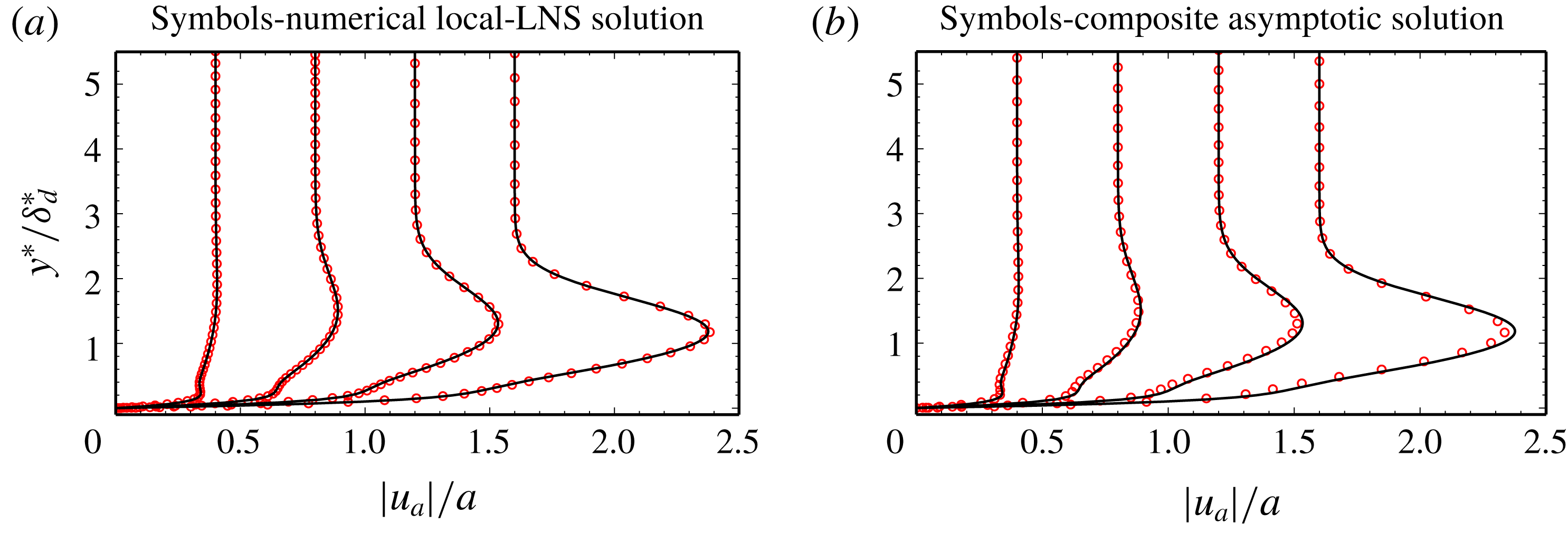
Acoustic streamwise velocity perturbation profiles scaled by
 $a=1/M_{\infty }$
(from left to right,
 $M_{\infty }=\{0.4,0.8,1.2,1.6\}$
,
 $\unicode[STIX]{x1D714}^{\ast }\bar{\unicode[STIX]{x1D708}}_{\infty }/\bar{U}_{\infty }^{2}\times 10^{6}=\{1.120,0.985,0.876,0.794\}$
and
 $R=70.2\times 10^{6}$
).
 $\unicode[STIX]{x1D6FF}_{d}^{\ast }$
represents the boundary layer displacement thickness. Black solid lines – numerical LUBLE solution.

The steady adjoint computation is a forced problem and thus needs to be addressed differently than the homogeneous problem at the inflow. At this streamwise position, we approximate the AHLNS with the local adjoint linearised Navier–Stokes (LNS) by introducing
 $$\begin{eqnarray}\tilde{\boldsymbol{q}}_{s,w}(x,y)=\tilde{\boldsymbol{q}}_{s,w}(y)\text{e}^{\text{i}(-\unicode[STIX]{x1D6FC}_{1}+\unicode[STIX]{x1D6FC}_{a})x},\end{eqnarray}$$
whereas at the outflow we impose
 $$\begin{eqnarray}{\displaystyle \frac{\unicode[STIX]{x2202}\tilde{\boldsymbol{q}}_{s,w}}{\unicode[STIX]{x2202}x}}=\text{i}(-\unicode[STIX]{x1D6FC}_{2}+\unicode[STIX]{x1D6FC}_{a})\tilde{\boldsymbol{q}}_{s,w}.\end{eqnarray}$$
4 Numerical results and comparison with literature
4.1 Stokes layer
The T–S wave solution is very sensitive to changes in the Stokes layer. Therefore it is important to guarantee an accurate representation of this field. For validation we introduce the ansatz
 $$\begin{eqnarray}\boldsymbol{q}_{a}(x,y)=\hat{\boldsymbol{q}}_{a}(y)\text{e}^{\text{i}\unicode[STIX]{x1D6FC}_{a}x},\end{eqnarray}$$
into the homogeneous HLNS equations and solve for
 $\hat{\boldsymbol{q}}_{a}(y)$
with appropriate boundary conditions. The resulting governing equations, henceforth denoted local LNS, are similar to the compressible linear stability equations, but with the non-parallel steady base flow terms retained in the equation set.
In figure 1(a) we compare numerical solutions of the LUBLE and of the local-LNS approaches for Mach numbers ranging from low subsonic to moderate supersonic regimes; very good agreement between the two approaches is evident. In figure 1(b) we replicate the same flow conditions and compare the LUBLE with the high Strouhal number asymptotic solution (2.24). Good agreement is found, with only minor differences between the two radically different treatments. These differences are more noticeable in an overlap region due to the matching of the inner and outer layer solutions, neither of which are strictly valid there.
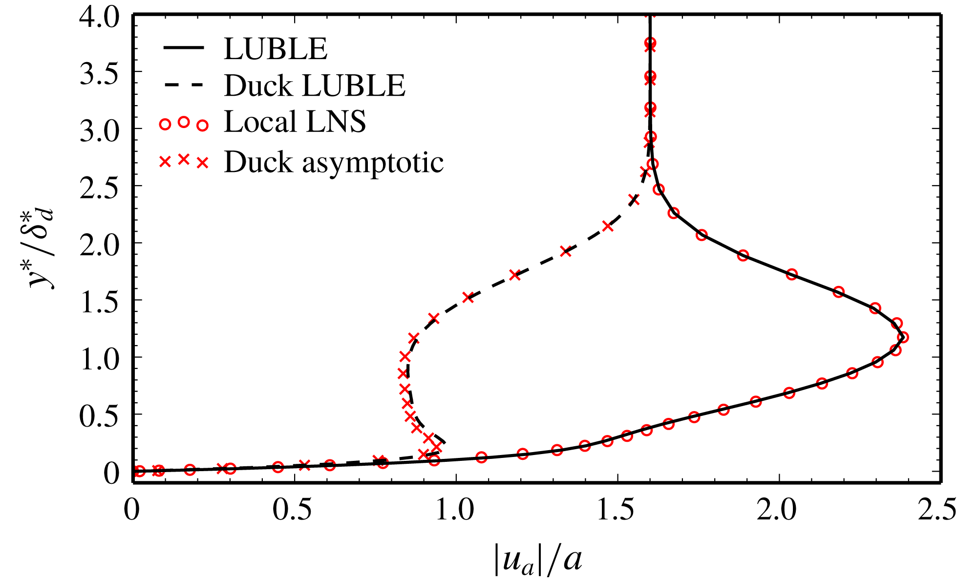
Lastly, we perform a comparison between the LUBLE numerical solution and the asymptotic solution of Duck (Reference Duck1990) in figure 2. In addition, we have replaced the governing equations of the LUBLE solver with those presented by Duck (Reference Duck1990) and computed a numerical solution (denoted ‘Duck LUBLE’ in the legend). On the one hand, there is good agreement between the asymptotic solution of Duck and the numerical solution of the corresponding governing equations. This indicates that this asymptotic solution is correctly deduced. On the other hand, there is a mismatch between the solutions of the two different equation sets, both analytical and numerical. This implies that the equation sets themselves are not equivalent. Duck deduced the LUBLE by linearising the unsteady form of (2.6). While this route should be equivalent to the one taken in the present work, it appears that the time fluctuation of the ‘independent’ variable
 $\unicode[STIX]{x1D702}$
was not taken into account.
Acoustic streamwise velocity perturbation profile (
 $M_{\infty }=1.6$
,
 $\unicode[STIX]{x1D714}^{\ast }\bar{\unicode[STIX]{x1D708}}_{\infty }/\bar{U}_{\infty }^{2}\times 10^{6}=0.794$
and
 $R=70.2\times 10^{6}$
). Comparison between the present approach and Duck (Reference Duck1990).

4.2 Comparison with asymptotic theory and DNS
De Tullio & Ruban (Reference De Tullio and Ruban2015) compared triple-deck-based receptivity theory with DNS computations. Two types of wall perturbations were considered – Gaussian-shaped roughness elements and vibrating ribbons. This brief comparison with their work focuses on linear receptivity caused by localised surface roughness.
The test case consists of a Gaussian-shaped bump placed on an adiabatic flat plate at
 $x^{\ast }=L_{b}$
and an acoustic wave propagating downstream with non-dimensional frequency
 $F_{n}=f^{\ast }\bar{\unicode[STIX]{x1D707}}_{\infty }/\bar{\unicode[STIX]{x1D70C}}_{\infty }\bar{U}_{\infty }^{2}$
such that the first branch of neutral stability (B-I) coincides with the roughness position. We define the Reynolds number
 $R_{b}=L_{b}\bar{U}_{\infty }/\bar{\unicode[STIX]{x1D708}}_{\infty }$
. The Gaussian shape is described by
 $$\begin{eqnarray}\widehat{H}(x)=\exp \left[-{\displaystyle \frac{(x-x_{b})^{2}}{2(\unicode[STIX]{x1D6E5}/6)^{2}}}\right],\end{eqnarray}$$
where
 $\unicode[STIX]{x1D6E5}$
is the non-dimensional Gaussian shape width and
 $x_{b}=L_{b}/L$
. See table 1 of TR for a full definition of the test cases under analysis.
Our computational domain extends for approximately 30 T–S wavelengths and no less than 200 points per wavelength are used in the streamwise direction. In the wall-normal direction we use 62 Chebyshev polynomials. The results were checked to be grid independent to graphical precision, in other words finer meshes would give graphically indistinguishable results.
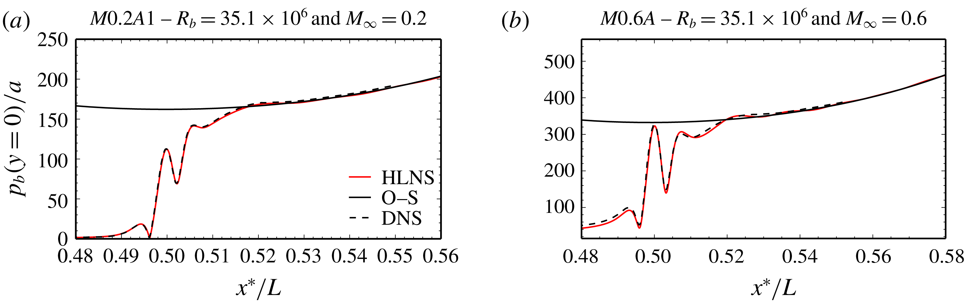
In figure 3 we present a quantitative comparison between the HLNS approach proposed in this paper and the DNS of TR. The wall-pressure perturbation amplitude
 $p_{b}(x,y=0)$
of the T–S wave is plotted against the streamwise position for test cases
 $M0.2A1$
and
 $M0.6A$
. Remarkable quantitative agreement is observed not only in the T–S dominated region downstream of the roughness element, which is positioned at
 $x_{b}=0.5$
, but especially so in the resonance interaction region. This highlights the DNS-like accuracy of the present approach, having used significantly less computational resources. While the precise duration is case dependent, a typical computation requires a total time of order 15 min using 20 cores. This strongly contrasts with the large computational times and computational power required to perform a study similar to that of TR. A more detailed comparison can be found in Raposo, Mughal & Ashworth (Reference Raposo, Mughal and Ashworth2018b
).
T–S wave wall-pressure amplitude evolution along the flat plate – comparison between HLNS, compressible O–S and TR’s DNS.
 $\unicode[STIX]{x1D6E5}/\unicode[STIX]{x1D706}_{\text{TS}}=1$
, where
 $\unicode[STIX]{x1D706}_{\text{TS}}$
is the T–S wavelength at the centre of the Gaussian bump.

4.3 Adjoint HLNS comparison with finite Reynolds number theory (FRNT)
Choudhari (Reference Choudhari1994) extended finite Reynolds number theory (Choudhari & Streett Reference Choudhari and Streett1992) to compressible flows and proceeded to study receptivity in the presence of localised suction and heating strips. The author addressed the acoustic-field signature problem using the compressible O–S equations with appropriate boundary conditions (forcing theory (Mack Reference Mack1984)), although scant details are provided concerning the exact form of the governing equations and of the adopted numerical procedures to account for wave reflection. Nonetheless, Choudhari’s approach takes into account the presence of the boundary layer and the effect of viscosity on the reflection and refraction process. This method contrasts with the thin boundary layer approximation employed in this paper, wherein the inviscid acoustic flow and the viscous boundary layer acoustic signature are treated separately. The main goal in the analysis that follows is thus to establish the extent to which the LUBLE can be used as an approximation to determine the acoustic-field signature in the boundary layer, and how the accuracy of this approximation varies with Mach number and angle of incidence.
Consider a localised, uniform-profile, suction strip centred at
 $\sqrt{R_{b}}=955$
and an incoming acoustic wave incident on the flat plate at an angle
 $\unicode[STIX]{x1D6E9}$
. The acoustic wave frequency is such that B-I coincides with the centre of the strip. An adiabatic wall condition is used with a constant stagnation temperature of 311 K for all cases. The numerical domain extends from
 $\sqrt{R_{b}}=423$
to
 $\sqrt{R_{b}}=1640$
, although in the interval
 $\sqrt{R_{b}}=423{-}733$
the solution is damped by means of a sponge layer to avoid spurious reflections. In the streamwise direction we employ 8000 points (approximately 200 points per T–S wavelength), whereas 62 Chebyshev polynomials are used in the wall-normal direction. This grid was confirmed to yield converged results up to graphical precision.
We seek to establish a comparison with figure 2(a–c) in Choudhari (Reference Choudhari1994). This involves calculating the so-called efficiency function based on the maximum of the streamwise mass-flux perturbation normalised by the acoustic wave pressure amplitude
 $$\begin{eqnarray}|\unicode[STIX]{x1D6EC}_{\unicode[STIX]{x1D70C}U,p}^{(j)}|=\max _{y}{\displaystyle \frac{|(\bar{U}\unicode[STIX]{x1D70C}_{b}+\bar{\unicode[STIX]{x1D70C}}u_{b})(x_{b},y)|}{|{\mathcal{F}}(\unicode[STIX]{x1D6FC}_{w})|p_{a,\infty }}},\end{eqnarray}$$
where
 $\unicode[STIX]{x1D6FC}_{w}=\unicode[STIX]{x1D6FC}_{\text{TS}}(x_{b})-\unicode[STIX]{x1D6FC}_{a}$
and
 ${\mathcal{F}}(\unicode[STIX]{x1D6FC})$
is the Fourier transform of the wall inhomogeneity profile. For a uniform-profile strip it assumes the form
 $$\begin{eqnarray}{\mathcal{F}}(\unicode[STIX]{x1D6FC})={\displaystyle \frac{1}{\unicode[STIX]{x1D6FC}}}\sqrt{{\displaystyle \frac{2}{\unicode[STIX]{x03C0}}}}\sin \left({\displaystyle \frac{\unicode[STIX]{x1D6FC}d}{2}}\right),\end{eqnarray}$$
where
 $d$
is the width of the suction strip. The reference length scale is the boundary layer displacement thickness at the centre of the suction strip. The instability amplitude at B-I is extracted by means of matching with a PSE solution
 $$\begin{eqnarray}(\bar{U}\unicode[STIX]{x1D70C}_{b}+\bar{\unicode[STIX]{x1D70C}}u_{b})(x_{b})={\displaystyle \frac{(\bar{U}\unicode[STIX]{x1D70C}_{b}+\bar{\unicode[STIX]{x1D70C}}u_{b})(x_{m})}{\exp \left[-\displaystyle \int _{x_{b}}^{x_{m}}\text{Im}(\unicode[STIX]{x1D6FC}_{\text{TS}})\,\text{d}\unicode[STIX]{x1D709}\right]}},\end{eqnarray}$$
where
 $x_{m}$
denotes the matching streamwise coordinate. The efficiency function is a natural quantity to compare different receptivity theories under the parallel flow assumption due to its independence of the wall-disturbance profile. For a finite-sized strip in non-parallel flows, the definition proposed in (4.3) is not strictly valid. In practice however, the efficiency function will converge to graphical precision provided the width of the suction strip is sufficiently small.
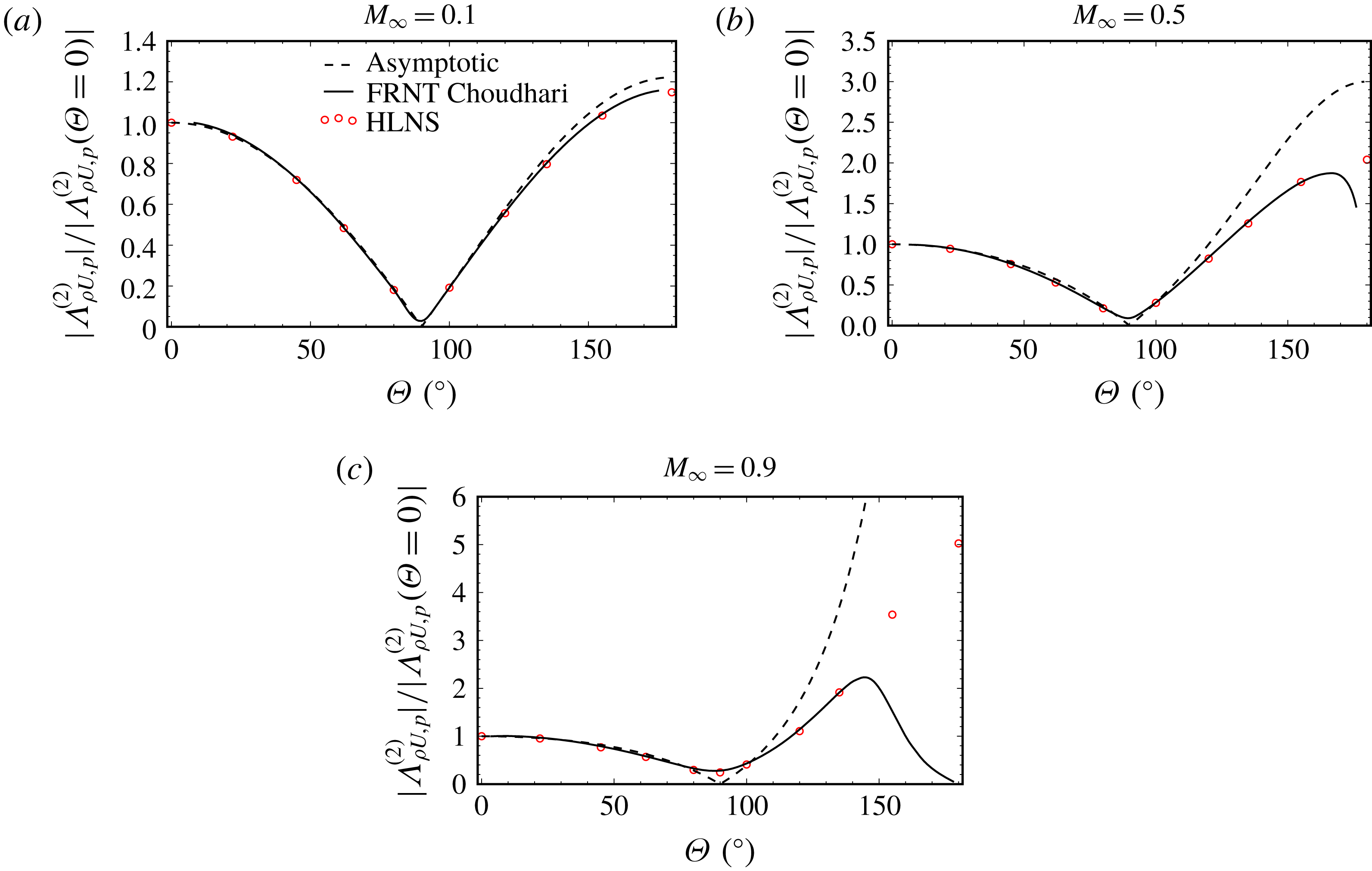
In figure 4 we assess the influence of the acoustic wave angle of incidence on the efficiency function (4.3). For each Mach number this quantity is normalised by its value at
 $\unicode[STIX]{x1D6E9}=0^{\circ }$
. The triple-deck-based asymptotic prediction (Ruban Reference Ruban and Kozlov1985) is then simply the ratio between the Stokes layer amplitudes as given by (2.23a
), namely
 $$\begin{eqnarray}{\displaystyle \frac{|\unicode[STIX]{x1D6EC}_{\unicode[STIX]{x1D70C}U,p}^{(j)}(\unicode[STIX]{x1D6E9})|}{|\unicode[STIX]{x1D6EC}_{\unicode[STIX]{x1D70C}U,p}^{(j)}(\unicode[STIX]{x1D6E9}=0)|}}={\displaystyle \frac{|\text{cos}(\unicode[STIX]{x1D6E9})(1+M_{\infty })|}{|1+M_{\infty }\text{cos}(\unicode[STIX]{x1D6E9})|}},\end{eqnarray}$$
and represented with dashed black lines in figure 4. This simple correlation always has a maximum for
 $\unicode[STIX]{x1D6E9}=180^{\circ }$
, i.e. for an upstream propagating wave. We also present numerical results obtained with the LUBLE-based model described in this work, as well as the results published by Choudhari (Reference Choudhari1994).
Efficiency function ratio against the acoustic wave angle of incidence for a suction strip wall mechanism. The legend of panel (a) is valid for all panels.

Remarkable agreement is found between asymptotic theory, forcing theory and a LUBLE-based approach at shallow angles of incidence. At fixed Mach number and increasing angle of incidence, we initially observe a departure of the asymptotic prediction from the still-in-agreement LUBLE and forcing theory. As the angle increases further, the LUBLE and forcing theory results begin to deviate. The deviation between the two approaches increases with growing Mach number.
Therefore, for any given Mach number there is an interval of angles of incidence for which the LUBLE-based approach and forcing theory agree, but wherein asymptotic theory predicts significantly different receptivity levels. This is in direct contradiction with Choudhari’s explanation for the deviation of the efficiency function from the asymptotic prediction. He argued that this could be explained by non-trivial sound wave refraction patterns and variations in the acoustic pressure field across the boundary layer. While this argument is still a prime candidate to explain the efficiency function dip for angles near
 $180^{\circ }$
, it cannot explain the inaccuracy of the asymptotic prediction at more moderate angles of incidence because the numerical LUBLE solution also does not account for this phenomenon and yet continues to be a reliable approximation. This behaviour indicates that the efficiency function has a non-trivial dependency on the form of the Stokes layer (see chapter 3 of Bernots (Reference Bernots2014)).
Forcing theory predicts a sudden decrease in receptivity at high angles of incidence, near
 $\unicode[STIX]{x1D6E9}=180^{\circ }$
. This trend starts to become evident at ever-smaller angles of incidence as the Mach number increases. According to Brand & Nagel (Reference Brand and Nagel1982), as one approaches
 $\unicode[STIX]{x1D6E9}=180^{\circ }$
the acoustic waves are refracted away from the wall and hence the acoustic-field boundary layer signature is weakened. This effect is all the more pronounced as the Mach number increases and explains the decreasing receptivity levels at high angles of incidence.
In conclusion, the LUBLE are a good approximation across the subsonic Mach number and angle of incidence parameter space, except for a band of angles for near upstream propagating waves. As the Mach number increases, use of the LUBLE model becomes questionable for an increasing range of incidence angles, for which viscous refraction should be taken into account. Non-parallel flow effects are relatively unimportant for the studied conditions.
Parametric study conditions – Mach number, frequency and T–S wave orientation.

4.4 Efficiency function
In this section the computational advantage afforded by the AHLNS is exploited to quantify the efficiency function for a range of frequencies, Mach numbers, spanwise wavenumbers, Reynolds numbers and wall perturbation mechanisms. The adjoint provides a means to obtain the receptivity sensitivity with respect to the latter two parameters virtually instantaneously.
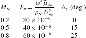
The range of Mach numbers, frequencies and T–S wave orientations considered is presented in table 1. The angle
 $\unicode[STIX]{x1D703}_{z}$
refers to the T–S wave orientation at the location of B-I as measured through the maximum streamwise mass flux. For conciseness, results for every possible combination of the parameter space are not presented. Instead, we start by analysing the effects of Mach number and frequency for 2-D T–S waves (
 $\unicode[STIX]{x1D703}_{z}=0^{\circ }$
). We then proceed to select one Mach number and wall actuation mechanism to analyse the effect of T–S wave obliqueness on the efficiency function for each frequency. Lastly, we evaluate how receptivity to oblique T–S waves varies with Mach number for a single frequency.
The quantity used to assess receptivity is not the efficiency function in its classical sense, where amplitudes are scaled back to the location of the wall inhomogeneity (Choudhari Reference Choudhari1994). Instead, we choose to perform backtracking to the first branch of neutral stability
 $x_{I}$
to provide a fairer comparison of amplitudes obtained for different locations of the wall perturbation. Mathematically, we evaluate
 $$\begin{eqnarray}|\unicode[STIX]{x1D6FA}_{\unicode[STIX]{x1D70C}U,\unicode[STIX]{x1D70C}U}^{(j)}|(x_{b})={\displaystyle \frac{(2\unicode[STIX]{x03C0})^{1/2}}{(\unicode[STIX]{x1D70C}u)_{a,\infty }}}A_{\unicode[STIX]{x1D70C}U}(x_{I})|A_{2}|(\widehat{H}(x)=\unicode[STIX]{x1D6FF}(x-x_{b})),\end{eqnarray}$$
where
 $A_{\unicode[STIX]{x1D70C}U}$
is the maximum amplitude of the streamwise mass-flux perturbation and
 $\left(\unicode[STIX]{x1D70C}u\right)_{a,\infty }=\text{cos}(\unicode[STIX]{x1D6E9})+M_{\infty }$
. The efficiency function is thus the T–S wave amplitude produced by a Dirac delta forcing
 $\unicode[STIX]{x1D6FF}(x-x_{b})$
evaluated through (2.36). We use the local boundary layer displacement thickness (
 $x=x_{b}$
) as a reference length scale, thus defining a local Reynolds number
 $R_{\unicode[STIX]{x1D6FF}}$
. An adiabatic wall condition is used with a constant stagnation temperature of 311 K for all cases.
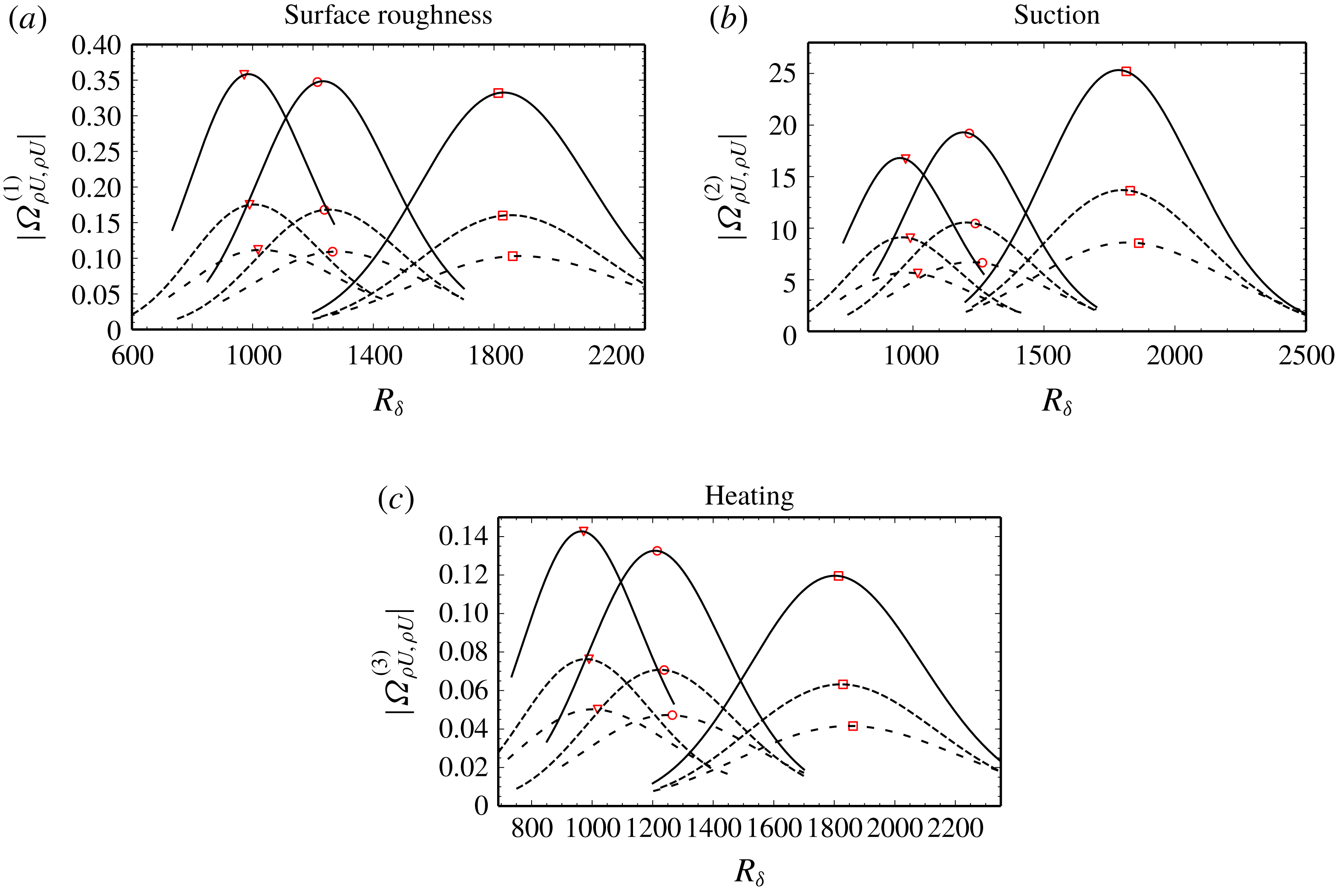
Figure 5 presents the efficiency function for 2-D T–S modes for all Mach numbers, frequencies and wall actuation mechanisms considered. The plots show the evolution of the efficiency function with the position of the wall inhomogeneity and highlight the location of the first branch of stability. For surface roughness at a fixed Mach number, a small increase in efficiency with the acoustic wave frequency is observed. This behaviour is identical at all Mach numbers. A similar trend is observed for wall heating, although the increase in efficiency with acoustic frequency is more pronounced. On the other hand, suction devices present an opposite trend. Note also how the maximal T–S amplitude is obtained if a roughness element is placed just downstream of B-I, whereas for suction and heating the optimal location occurs slightly upstream of this point. The boundary layer is receptive to lower acoustic frequencies in a large portion of the domain, but on the other hand higher frequencies influence the flow much further upstream. Lastly, for a fixed frequency, a decrease in efficiency for increasing free-stream Mach number occurs. However, it is worth noting that this trend is closely related to the choice of flow quantity used to define the T–S and acoustic wave amplitudes.
Efficiency function in function of local Reynolds number for different Mach numbers, frequencies and wall-disturbance mechanisms.
 $\unicode[STIX]{x1D703}_{z}=0^{\circ }$
; solid curves –
 $M_{\infty }=0.1$
; short dashed curves –
 $M_{\infty }=0.5$
; long dashed curves –
 $M_{\infty }=0.8$
; symbols – B-I location; square –
 $F_{n}=20\times 10^{-6}$
; circle –
 $F_{n}=40\times 10^{-6}$
; triangle –
 $F_{n}=60\times 10^{-6}$
.

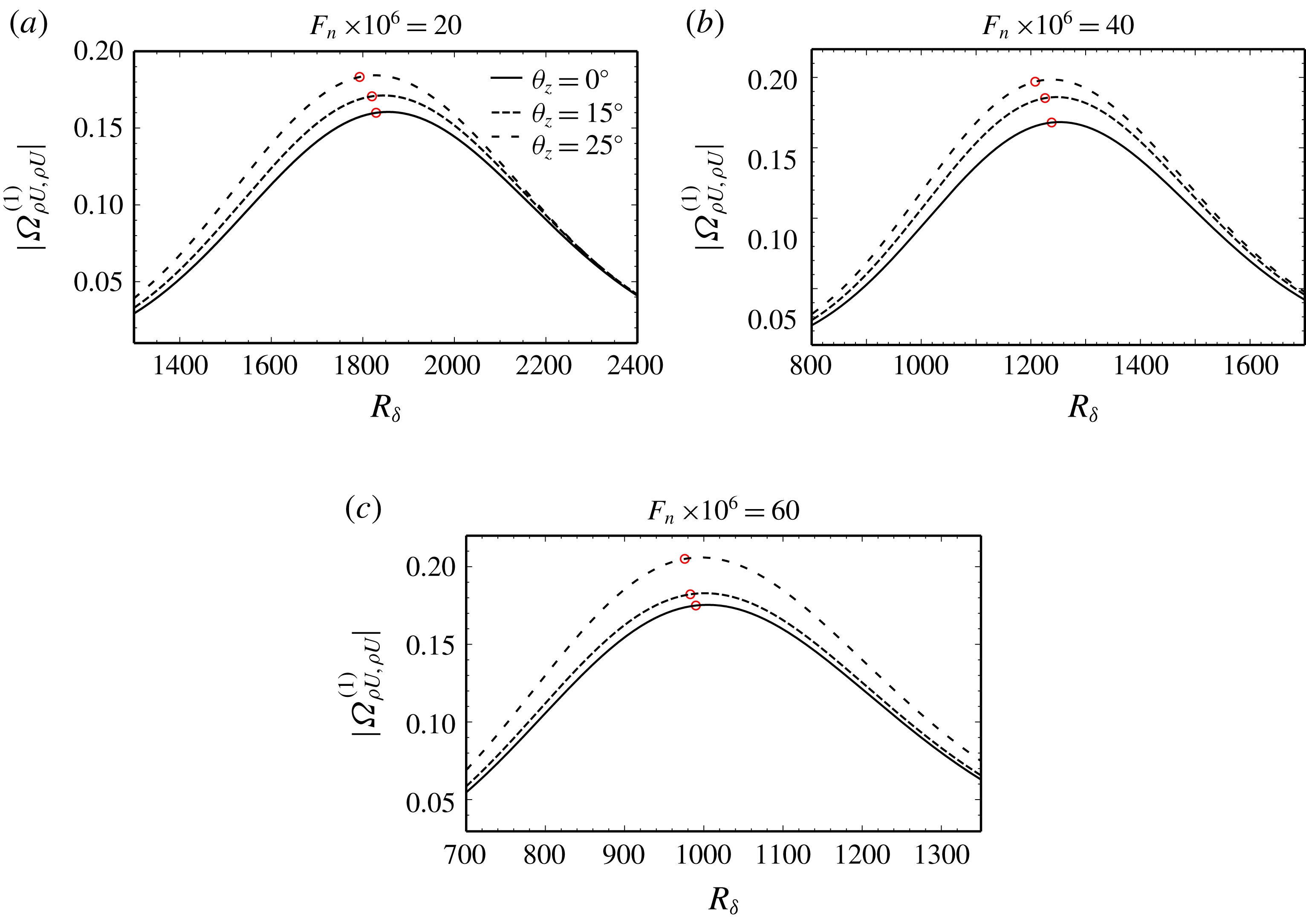
Surface roughness efficiency function in function of local Reynolds number for different frequencies and spanwise wavenumbers at fixed Mach number
 $M_{\infty }=0.5$
. Red circle – B-I location.

In figure 6 the free-stream Mach number is held constant at
 $M_{\infty }=0.5$
and focus is on surface roughness. For each acoustic frequency, we plot the efficiency function for three different T–S wave orientations. The results are consistent with what has previously been observed in the incompressible regime (Crouch & Bertolotti Reference Crouch and Bertolotti1992; Raposo et al.
Reference Raposo, Mughal and Ashworth2018a
) – the boundary layer is more receptive to oblique disturbances than to 2-D instabilities across the frequency parameter space. Although not presented here, a similar effect is observed for suction and heating. Conversely, for incompressible flow it is known that 2-D modes are more unstable than their oblique counterparts. However, as the Mach number increases, oblique first modes become the dominant instability (El-Hady Reference El-Hady1991). At
 $M_{\infty }=0.5$
this is still not the case, but at
 $M_{\infty }=0.8$
, both disturbances with
 $\unicode[STIX]{x1D703}_{z}=15^{\circ }$
and
 $\unicode[STIX]{x1D703}_{z}=25^{\circ }$
present higher amplification than those of the 2-D disturbance for
 $F_{n}=20\times 10^{-6}$
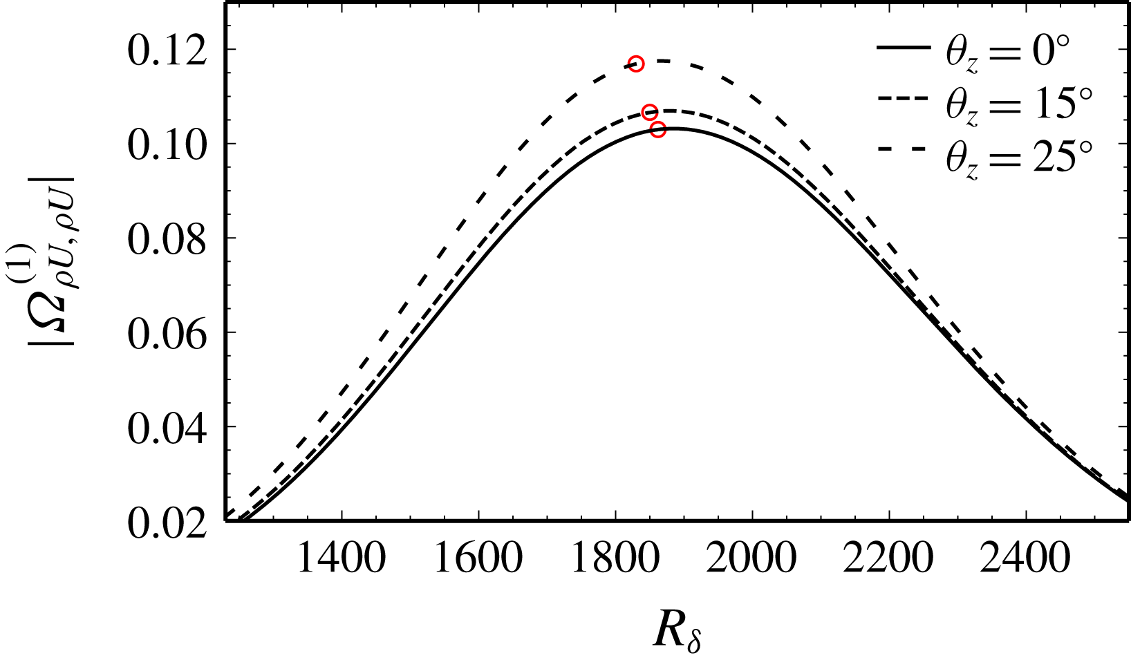
(not shown). Nonetheless, in figure 7 we observe that no similar inversion in trends occurs for receptivity, wherein oblique disturbances continue to be the most receptive. This indicates that linear growth at high subsonic and transonic Mach numbers may be dominated by 3-D disturbances because they are both more receptive to external disturbances and more unstable than their 2-D counterparts.
Surface roughness efficiency function in function of local Reynolds number for different spanwise wavenumbers at fixed Mach number
 $M_{\infty }=0.8$
and frequency
 $F_{n}=20\times 10^{-6}$
. Red circle – B-I location.

5 Conclusions
The acoustic receptivity model of RMA based on the HLNS equations was extended to the compressible regime. The corresponding adjoint treatment was introduced to facilitate rapid parametric investigations and an alternative formulation dedicated to sensitivity to the acoustic wave angle of incidence was proposed. The amplitude equations based on adjoint solutions provide a feasible and numerically efficient means of accounting for the effects of variances in the free-stream acoustic field and surface finish on the T–S wave amplitude. This allows for a rapid and high-fidelity construction of a receptivity amplitude probability density function in the uncertainty quantification analysis described by RMA. This approach yields considerable advantages over DNS for it displays similar accuracy while also reaping the benefits of exploiting viscous–inviscid decoupling and Fourier decompositions in time and spanwise directions for reduced computational times.
Motivated by the need to validate numerical solutions of the LUBLE, high Strouhal number asymptotic solutions of these equations were derived. Incidentally, this showed remarkably different results compared to the earlier work of Duck (Reference Duck1990), whose equations lack additional terms. A third approach employing the linear stability equations was used to support the LUBLE-based results presented in this paper. Often in the literature, acoustic receptivity studies are restricted to downstream travelling waves aligned with the free-stream flow direction. In this work the LUBLE were generalised for cases where 2-D acoustic waves are impinging on a flat plate at an angle. This configuration is of practical interest to model both flight conditions, where acoustic disturbances from the engines impinge at highly oblique angles, and wind-tunnel experiments, where acoustic disturbances tend to be reflected at the walls. It was shown that these governing equations are capable of modelling the boundary layer acoustic signature for a vast range of obliqueness values, substantially more than asymptotic predictions would anticipate. Nevertheless, there is a small range of inclination angles for near upstream travelling waves, growing with Mach number, where the LUBLE must be replaced with a model accounting for wall-normal unsteady pressure variations across the boundary layer.
It must be highlighted that the close agreement with the quasi-parallel theory of Choudhari (Reference Choudhari1994) does not imply that a simplified model utilising a parallel flow assumption is preferable. Generally, where oblique disturbances exist and for curved bodies such as aerofoils, substantial non-parallel effects are expected. In fact, the receptivity model presented in this paper is intended to serve as a stepping stone towards the more general problem of an infinite swept wing. This, we believe, can be achieved by generalising the model framework presented in this work to curvilinear coordinates. In addition, the inviscid acoustic wave propagation problem must be solved to provide boundary conditions to the LUBLE.
Lastly, we evaluated the efficiency function for a range of streamwise positions, Mach numbers, frequencies and spanwise wavenumbers for localised surface roughness, suction and heating. One of the most prominent trends is the increase in efficiency function with the obliqueness of the first-mode instability, irrespective of Mach number, frequency, Reynolds number and wall actuation mechanism. This result indicates that in near sonic flows 3-D instabilities are both more receptive and more unstable than 2-D ones, making them a prime candidate to trigger transition to turbulence.
Acknowledgements
This project has received funding from the European Union’s Horizon 2020 research and innovation programme under the Marie Sklodowska-Curie grant agreement no. 675008. A small part of this work was presented at AIAA Aviation Conference 2018 (Raposo et al. Reference Raposo, Mughal and Ashworth2018b ).
Supplementary materials
Supplementary materials are available at https://doi.org/10.1017/jfm.2019.601.