Nomenclature
- Symbols
-
Abbreviations
-
 $\rho$
-
mass density kg/m3
-
$\tau$
-
shear stress Pa
- t
-
time (s)
- u
-
velocity (m/s)
- p
-
static pressure (Pa)
-
$\tau_{\rm tj}$
-
viscous stress tensor
-
$e_t$
-
total energy (J/kg)
-
$h_t$
-
total enthalpy (J/kg)
- T
-
temperature (K)
- q
-
heat energy (J/kg)
- i, j
-
direction
- k
-
turbulent kinetic energy (m2/s2)
-
$\varepsilon$
-
turbulent Kinetic energy dissipation rate (m2/s3)
-
${\omega}$
-
specific dissipation rate
-
$\bar{\rm G}$
k
-
generation of turbulence kinetic energy due to mean velocity gradients
-
$\bar{\rm G}\omega$
-
represents the generation of
${\omega}$
-
$Y_k$
and
$Y_{\omega}$
-
the dissipation of k and
${\omega}$
due to turbulence -
$S_{\rm k}$
and
$S_{\omega}$
-
user defined source terms
-
$\Gamma_{\rm k}$
and
$\Gamma_{\omega}$
-
represent the effective diffusivity of k and
${\omega}$
- MW
-
molecular weight (kg/mol)
- Ri
-
net rate of production of species i
- Si
-
source term of the chemical reaction
- Yi
-
local mass fraction of each species i
- Ji
-
diffusion flux of species i
-
v
$^{\prime}$
-
stoichiometric coefficient
-
$\varepsilon$
/k
-
turbulent mixing frequency
- A and B
-
eddy dissipation model empirical constants
- K
-
reaction rate proportionality constant
-
$\mu_t$
-
turbulent viscosity (kg/(m·s))
-
$\sigma$
-
turbulent Prandtl number
-
$\omega$
-
specific dissipation rate (1/s)
-
$\kappa$
-
reacting volume fraction
- U
-
mean velocity
- ṁ
-
mass flow rate
- M∞
-
Mach number
-
$\theta$
-
shock angle
- Cd
-
strut drag coefficient
- xr
-
recirculation length
- xr /h
-
normalised recirculation length
-
$\eta$
-
efficiency


1.0 Introduction
The scramjet engines are the most emerging engines in the field of hypersonic propulsio [Reference Curran11, Reference Lv, Yan, Lei, Hou, Chen, Wang, Qi, Yu and Yu30, Reference Winter49]. They have no moving parts and use atmospheric air as an oxidiser, reducing the weight of the oxidiser, making the engine more efficient and low cost, and travel at a higher speed than other propeller-driven jet engines and generate higher specific impulse than rocket engines. Scramjet engines are even reusable, which cuts the high cost of launching multiple satellites into Earth’s orbit [Reference Billig4, Reference Gamba and Mungal15, Reference Moradi, Mahyari, Gerdroodbary, Abdollahi and Amini33, Reference Zhao, Li and Gong52]. Scramjet engines compress the air and stabilise the shocks formed due to hypersonic speed. The compressed air travels into the engine at a supersonic speed, which gives a short residence reaction time for the gases to mix with the fuel. This shorter residence time causes very challenging and difficult conditions for stabilising and effective combustion performance [Reference Billig and Schetz3, Reference Choubey, Gaud, Fatah and Devarajan8, Reference Manna, Behera and Chakraborty31].
The scramjet combustor is a crucial part of the scramjet engine, the thrust-to-drag percentage correlates to the combustor width-to-length ratio when self-ignition takes place. However, the combustor length tends to increase with igniting delay and airflow rate. Consequently, a short combustor is required. This is achieved with the help of flame holder, which shortens the period it takes for combustion to occur and provides complete reactive species for oxidation processes over a short interval. Within the supersonic combustor, the strut is frequently utilised as an injection device for fuel. Fuel flows horizontally via the strut’s baseline plane to enhance the combustion process and supersonic air mixing.
A lot of research has been conducted on this part, where Waidmann and his team [Reference Waidmann, Alff, Brummund, Böhm, Clauss and Oschwald46, Reference Waidmann, Brummund and Nuding47, Reference Waidmann, Brummund and Nuding47] conducted experiments on the DLR scramjet combustor model. These experimental results helped a lot in understanding the flow physics in the scramjet combustor, these results are being used to validate the computational solver and support the study in detail on enhancing the combustor’s performance. Oevermann [Reference Oevermann35] conducted a detailed computational analysis of turbulent hydrogen using a turbulent computational study. Many researchers conducted various computational studies on enhancing the performance of the combustors using different techniques, like centre-lobed strut [Reference Huang, He, Wang, Qin, Wei and Shi20, Reference Li, Wang and Li29, Reference Pandey, Roga and Choubey37], dual strut [Reference Choubey, Solanki, Patel, Devarajan and Huang9, Reference Kummitha and Pandey23, Reference Nair, Ananthu and Narayanan34, Reference Quan, Chang, Kong, Lv and Wu39], and transverse injection [Reference Choubey, Suneetha and Pandey10, Reference Dong, Liao, Choubey and Huang13, Reference Huang, Du, Yan and Xia18].
The design of the combustor, such as the fuel injector location, injection angle, shock wave generation angle and so forth, determines the scramjet combustor’s overall proficiency [Reference Sharma, Eswaran and Chakraborty41, Reference Sharma, Eswaran and Chakraborty42]. The field of scramjet has undergone multiple reviews [Reference Chang, Zhang, Bao and Yu6, Reference Choubey, Devarajan, Huang, Mehar, Tiwari and Pandey7, Reference Seleznev, Surzhikov and Shang40]. It displays a variety of scramjet combustor shape types [Reference Shen, Huang, You and Yi43, Reference Li, Manh, Gerdroodbary, Nam, Moradi and Babazadeh28]. However, several fuel injection techniques and locations [Reference Kumar, Das and Sheelam21, Reference Li, Manh, Gerdroodbary, Nam, Moradi and Babazadeh28, Reference Yan, Liao, Meng, Li and Huang51] have also been used to comprehend the combustion properties. To get the best performance, many fuel injection strategies have been used [Reference He, Cao, Huang, Qin and Yu17], including transverse [Reference Wu, Zhang, Yao and Fan50] and parallel [Reference Cai, Zhu, Sun and Wang5] fuel injection techniques.
Using the transverse fuel injection approach, Lang-quan Li et al. [Reference Li, Huang, Yan, Du and Fang26] examined the combustor’s mixing effectiveness. An extra ramp was constructed to analyse the fuel to optimise mixing along with a reduction in stagnation pressure with mixing length and penetration height. Significant stream-wise vorticity was found to have a significant impact and to be a useful characteristic in transverse injection. Researchers [Reference Aso, Inoue, Yamaguchi and Tani1, Reference Fuller, Mays, Thomas and Schetz14, Reference Mays, Thomas and Schetz32] discovered that slanting the injection angle downstream of the crossflow reduces bow shock and pressure loss near the injector. Gruber et al. [Reference Gruber, Nejad, Chen and Dutton16] explored an experimental study to investigate the outcome of injector shape on injection angle. According to the study, injector configuration does not influence the perpendicular jet flow field, however altering the injection angle significantly does.
The following recent studies have advanced scramjet mixing and combustion, Zeng et al. [Reference Zeng, Wang, Huang, Fan and Wang62] used boron-containing solid propellant with central strut injection in ground-based direct-connect experiments and simulations under Mach 6 flight conditions, achieving up to 88% combustion efficiency at equivalency ratio ≈1. In a cavity-based combustor operating at Mach 2–2.7, Chakravarthy et al. [Reference Chakravarthy, Randive and Pati56] investigated the effects of injection angle (15°–60°) and jet-to-cross-flow pressure ratio (0.5–1.2). They discovered that a 45° angle at a pressure ratio ≈ 0.8 produces the best recirculation and mixing performance without choking. Using unsteady RANS, De Oliveira Júnior et al. [Reference Costa Júnior, de Oliveira Júnior and de Paula Toro57] examined transverse hydrogen injection at Mach 2.5 and found oscillatory shock and separation zones that affect thrust, mixing and flame propagation [Reference Costa Júnior, de Oliveira Júnior and de Paula Toro57]. In their RANS-SST simulations of multi-pylon ethylene fuel injection in supersonic cold flow, Xia et al. [Reference Xia, Sun, Wang, Hu, Qiang, Zhu and Zhang61] showed that spanwise pylon configurations outperform streamwise and oblique design in terms of penetration depth and mixing efficiency. The impact of strut-based injection techniques, such as strut-cavity, multi-strut, and ramp-plus-strut, on mixing, flame stability and pressure loss across various fuels is thoroughly compared in the review of Suppandipillai et al. [Reference Venkateswarlu and Kota Reddy59]. Due to improved fuel distribution and advantageous oblique shock interactions, Bogi Sai et al. [Reference Bogi Sai, Vinay, Akula Sai, Sundaraswaran, Raj, Sharma and Sanal Kumar55] showed that a single-strut combustor with dual fuel injection sites may increase mixing and combustion efficiency (up to about 95%).
An analysis of hydrogen transverse injection modes published in the International Journal of Hydrogen Energy by Bezerra et al. [Reference Bezerra, Araújo, Souza, Marinho and Toro54] revealed that the injection scheme has a major impact on fuel-air mixing and combustor performance as a whole. In their computational evaluation of the impact of wedge-strut injector configurations in hydrogen-fueled flow, Kumar and De [Reference Kummitha and Kandula58] reported improved radial fuel penetration and spatial mixing via optimal nozzle placement. In their study of cavity plus ramp layouts in strut-based combustors across Mach 2–2.7, Atci et al. [Reference Atci, Suppandipillai, Sharma, Karaca and Jayaraman53] verified that combined geometry designs optimise mixing and recirculation efficiency. Lastly, asymmetric and two-strut configurations in Mach 2.5 hydrogen combustors were investigated by Choubey et al. [Reference Choubey, Solanki, Patel, Devarajan and Huang9] (published late 2023/early 2024), who concluded that vortex formation from optimised strut geometry and multi-strut layouts increases turbulent mixing [Reference Choubey, Solanki, Patel, Devarajan and Huang60].
All of these approaches were studied to improve the blending of high-speed airflow with the fuel injected and hence the effectiveness of a scramjet engine. The authors discovered that each of these methods significantly improved scramjet performance. According to the studies mentioned above, no research has been done on the orientation of the strut base or the injection of fuel in both directions, which can improve the circulation regions and widen the area of combustion. Therefore, in this investigation, an innovative strategy is implemented by converting the conventional strut base configuration to a flat base with two edges to enable the transverse fuel injection at a variety of angles. The interface between the fuel and supersonic airflow can be profoundly regulated by this fuel injection technique.
2.0 Numerical Approach
2.1 Governing equations
This work uses contemporary computer simulations to provide a comprehensive numerical description of the combustion processes in a supersonic engine. To assess performance in high-speed flow conditions, a density-based compressible solver is used to solve the Reynolds-averaged Navier-Stokes (RANS) equations [Reference Suneetha, Randive and Pandey44]. Understanding the fundamental mathematical equations for energy, momentum and mass conservation is necessary to accurately reproduce the complex mechanics of the scramjet combustor. These governing equations are represented as Equations (1–3).
Mass conservation:
 \begin{align}\frac{{\partial \rho }}{{\partial t}} + \frac{\partial }{{\partial {x_i}}}\left( {\rho {u_i}} \right) = 0\end{align}
Momentum equation:
 \begin{align}\frac{\partial}{\partial t}(\rho u_{i}) + \frac{\partial}{\partial x_{i}} (\rho u_{i} u_{j}) = -\frac{\partial P}{\partial x_{i}} + \frac{\partial}{\partial x_{i}} (\tau_{ij})\end{align}
Energy equation:
 \begin{align}\frac{\partial}{\partial t}(\rho e_{i}) + \frac{\partial}{\partial x_{i}} (\rho h_{i} u_{j}) = \frac{\partial}{\partial x_{i}}(\tau _{ij}{u_i} - {q_i})\end{align}
The species transport equations delineate the mechanisms by which specific chemical species (e.g., H2, O2, H2O, radicals, etc.) are conveyed, intermixed and generated/consumed within the flow field.
Species Transport
 \begin{align}{{\partial \left( {\rho {Y_i}} \right)} \over {\partial t}} + \nabla \cdot \left( {\rho u{Y_i}} \right) = {\rm{\;}} - \nabla \cdot {J_i} + {R_i} + {S_i}\end{align}
2.2 Turbulence modelling
The correctness of the flow deficiency is dependent on the turbulence model, which is crucial in simulating chemically reactive flow systems. A popular SST k-ω turbulent model is used in the current simulations. The SST K-ω model utilises k-ε in the fluid region and k-ω to solve the boundary layer. Using the SST k-ω turbulence model, jet flow patterns and mixing layers can be precisely predicted to describe the complex instability characteristics in supersonic combustion [Reference Banica, Scheuermann, Chun, Weigand and Von Wolfersdorf2, Reference Wang, Zhong, Gu and Zhang48]. Equations (5) and (6) list the governing equation for the turbulence models.
SST K-
 $\boldsymbol{\omega}$
model
 \begin{align}{\partial \over {\partial t}}\left( {\rho k} \right) + {\partial \over {\partial {x_i}}}\left( {\rho k{u_i}} \right) = {\partial \over {\partial {x_j}}}\left( {{\Gamma _k}{{\partial k} \over {\partial {x_j}}}} \right) + {\bar G_k} + {Y_k} + {S_k}\end{align}
 \begin{align}{\partial \over {\partial t}}\left( {\rho \omega } \right) + {\partial \over {\partial {x_i}}}\left( {\rho \omega {u_i}} \right) = {\partial \over {\partial {x_j}}}\left( {{\Gamma _\omega }{{\partial \omega } \over {\partial {x_j}}}} \right) + {\bar G_\omega } + {Y_\omega } + {S_\omega }\end{align}
2.3 Chemistry-turbulence integration
Turbulence chemistry is studied using the eddy-dissipation combustion model, a popular combustion modeling technique [Reference Dharavath, Manna and Chakraborty12, Reference Huang, Pourkashanian, Ma, Ingham, Luo and Wang19, Reference Kummitha, Pandey and Gupta24]. The study mainly focuses on the combustion chemistry at different strut base angle injection and their combustion performances at various angles. Examining the interplay of chemical reactions is crucial since a single-step chemistry reaction is adequate for assessing all the parameters affecting scramjet combustion engines [Reference Kumaran and Babu22, Reference Qin, Agarwal and Zhang38]. Using this strategy can significantly reduce computational costs while properly forecasting overall performance indicators. A single-step non-reversible reaction (7) is used in this study.
 \begin{align} 2{H_2} + {O_2} = 2{H_2}O \end{align}
Equations (8) and (9) are used in the eddy dissipation approach to determine the reaction rate K.
 \begin{align}R_{i,k} = v_{i,k}^{\prime} MW_{i}A\rho \frac{\varepsilon}{k} \frac{Y_{r}}{{K v_{r,k}^{\prime}MW_{r}}}\end{align}
 \begin{align}R_{i,k} = v_{i,k}^{\prime} MW_{i}AB \rho \frac{\varepsilon}{k} \frac{{\sum_{p}Y_{p}}}{\sum\nolimits_{j}^N v_{j,k}^{\prime\prime}MW_{j}}\end{align}
Since fuel and oxidisers react instantly and produce products instantly after they do so, this eddy dissipation concept enables an indefinitely rapid rate of reaction chemistry. In this chemistry model, the chemical reaction proceeds more quickly than the flow process. The amount of time it takes for the reactant to combine at the molecular level determines the reaction rate. The turbulent kinetic energy as well as dissipation rate, or
 $\alpha {\varepsilon \over k}$
, determine the mixing time and response rate, which are controlled by the turbulent flow structures. The species formation rate according to the eddy dissipation theory is defined as
 \begin{align} {R_{ed}} = \rho {\varepsilon \over k}{A_{ed}}min\left[ {{Y_f},{{{Y_0}} \over s},\;{B_{ed}}{{{Y_p}} \over {1 + }}} \right]\end{align}
where s is the oxidiser-to-fuel equilibrium mass ratio,
 ${Y_f},\;{Y_0},\;{Y_p}$
are the mass fractions of fuel, oxidiser, as well as product, respectively, and
 ${A_{ed}},\;{B_{ed}}$
are the model constants.
2.4 Numerical method
The flow domain and the combustion processes are simulated by discretising the governing equations employing the finite volume approach (FVM) using an explicit formulation. ANSYS FLUENT 24.2, a potent tool for simulating compressible flow and high-speed combustion, uses this method. The RANS method was used to solve the set of governing equations. A density-based model with twofold accuracy is employed for steady-state computations. A thorough examination of the combustion dynamics inside the scramjet combustor is made possible by this numerical method.
A detailed sketch of DLR scramjet model.

3.0 Setup
3.1 Geometry
The current analysis uses a scramjet combustion chamber design that utilises the geometry obtained from the DLR scramjet combustor [Reference Waidmann, Alff, Brummund, Böhm, Clauss and Oschwald46]. The centre lobbed strut with a 6-degree divergence and a length of 32 is used by varying the angle from the strut base mid-point. The complete combustor dimensions are adopted from the standard DLR model where the outer dimensions are unchanged. A 340 mm length combustor part with a 50 mm inlet and 62 mm outlet is considered in this study. Figure 1 depicts the two-dimensional computational space employed in this investigation. The supporting structure strut works as a flame holder, while it generates shockwaves. The strut base is altered with different angled base from the centre point of the strut base. The fuel injection point is now divided into two and placed at the centre of the top and bottom of the slanted strut base. The angles used for the strut base are 30 degree, 45 degree and 60 degree as shown in Figure 2.
Strut base with 30 degrees (a); strut base with 45 degrees (b); and strut base with 60 degree (c).

3.2 Meshing
Discretisation is an important stage in computational fluid dynamics (CFD) simulations because it entails breaking down the geometric domain into smaller, more manageable parts that accurately reflect the flow field. This approach establishes the groundwork for numerically solving fluid flow’s governing equations. This study adopts a mesh size of 3e-04 with an inflation of ten layers and a first layer thickness of 5e-05 for finer mesh size.
3.3 Boundary conditions
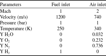
The criteria for boundaries employed in this study were adapted following Waidmann et al. [Reference Waidmann, Alff, Brummund, Böhm, Clauss and Oschwald46]. The pressure far-field, wall with no-slip wall condition and pressure outlet parameters are applied in the current numerical simulations. At the air inlet and fuel, the boundary condition is set to pressure far-field, and the outlet of the combustor is set to the pressure outlet. The top wall, bottom wall and strut are set to the stationary walls with no-slip conditions. Table 1 details the parametric boundary conditions for air and fuel. The static pressure at both inlets is set to 1 kPa, with the air intake at Mach 2 and the fuel inlet at Mach 1. The mass percentages of the species for both air and fuel inlets are likewise shown in Table 1, with distinct values for each. All simulations are run at zero Pascal operating pressure, guaranteeing that the given input conditions and shape do not affect the flow dynamics.
Boundary values

Mesh configuration.

Grid independence test calculating the temperature values at the outlet of the combustor for different mesh elements.

3.4 Grid independence test
In computational studies, the solution to flow fields is determined by numerically solving governing equations over the entire domain. This process involves discretising the domain into multiple mesh elements (Figure 3). The simulation’s precision improves as the quantity of mesh elements rises; nevertheless, this greatly increases processing time. A mesh convergence test is done to ascertain the bare minimum of mesh elements necessary for dependable findings to strike a compromise between computational performance and result correctness. In this work, several mesh sizes were used to calculate the wall Y
 $\texttt{+}$
, mixing efficiency and peak temperature in the scramjet combustor’s exit in a reactive flow. As depicted in Figure 4, the wall Y
 $\texttt{+}$
value was 90 when the 30,000 number of mesh elements are adopted for the simulation, but as increasing the number of mesh elements it is observed the reduction in wall Y
 $\texttt{+}$
where we can observe the wall Y
 $\texttt{+}$
value of 5 at 100,000 number of mesh elements, and 4 at the 110,000 number of mesh elements. In SST K-omega model the wall Y
 $\texttt{+}$
values below 5 are acceptable for the simulations. Similarly mixing efficiency at 30,000 number of mesh elements possess a 75% mixing efficiency as increasing the number of mesh elements around 90,000 the mixing efficiency reaches up to 98% further increasing to 100,000 and 110,000 the mixing efficiency reaches up to 100%. Even the peak temperature values converge after exceeding 90,000 number of mesh elements. This indicates that further increasing the mesh count beyond 1 lakh does not lead to any significant variation in the results. Therefore, a mesh size of 5e-04 m, corresponding to 1 lakh elements, was selected as the optimal configuration with less computational cost and optimum accuracy.
4.0 Results
4.1 Validation
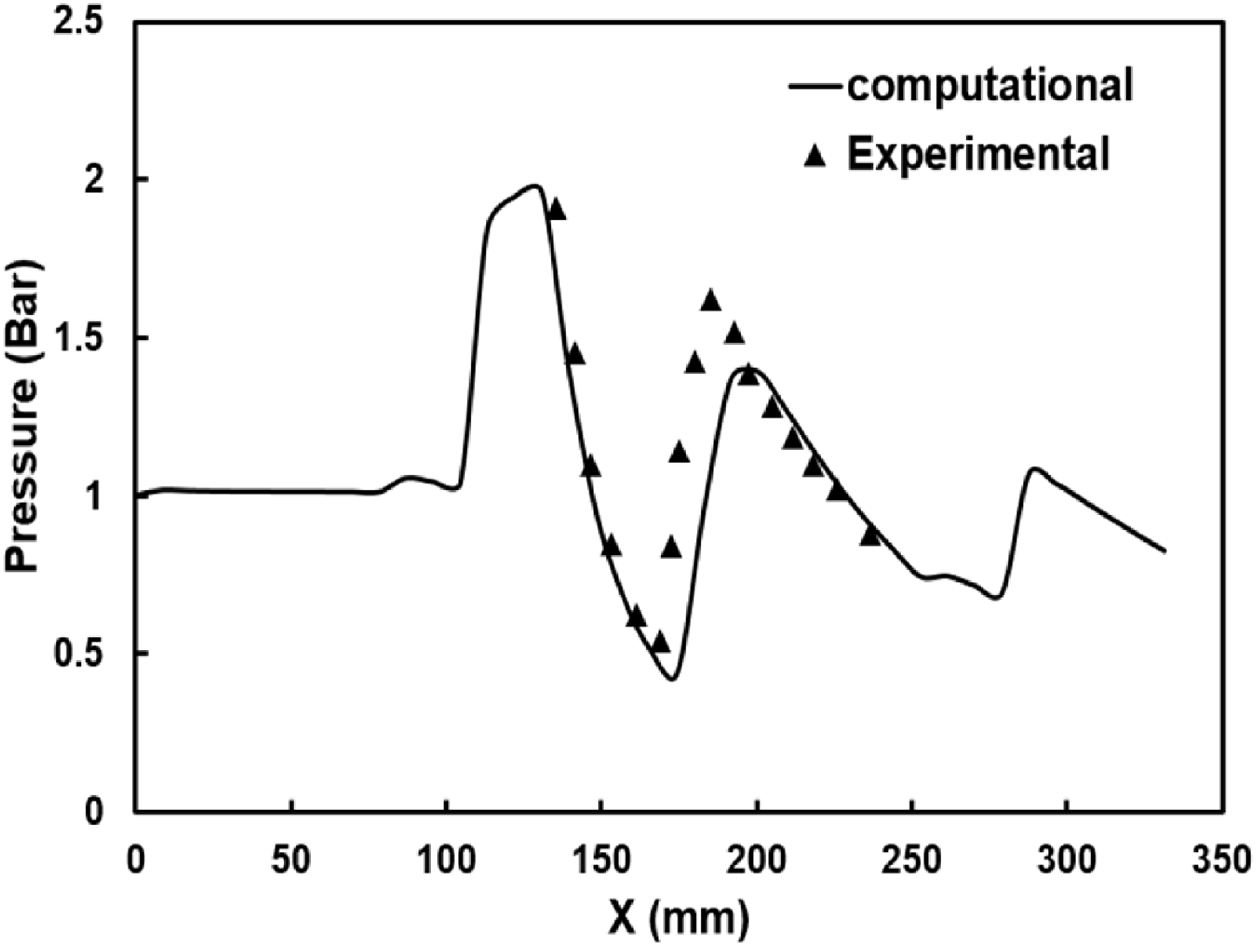
The complete work was studied using computational simulations, as numerical simulations take less time and less cost for a study instead of experimental work. However, it can also predict false results if the conditions are not set properly. These numerical outcomes are checked with experimental data to illustrate (or validate) their precision. The computational findings reported here are contrasted with the experimental findings of Waidmann et al. [Reference Waidmann, Alff, Brummund, Böhm, Clauss and Oschwald46]. Figures 5, 6 and 7 demonstrate an adequate consistency regarding the experimental and computational results on the temperature at different points along the length inside the combustor, pressure values on the bottom wall and the shadowgraph picture. A reasonable agreement was observed between the two, confirming the accuracy of the computational model and the validity of the solver used in this investigation. The disparity between the experimental and numerical temperature profiles in Figure 7 principally results from heat losses in the experimental apparatus, simplifications in combustion modelling. Apart from experimental heat losses, other contributing factors include limitations of the eddy dissipation model with single-step chemistry, which may not fully capture turbulence–chemistry interactions, leading to variations in local temperature predictions. Additionally, the use of adiabatic wall boundary conditions in the simulation, in contrast to the heat loss present in experiments, could influence downstream temperature profiles.
Static pressure at the bottom wall of the combustor.

The shadow picture from Waidmann et al. [Reference Waidmann, Alff, Brummund, Böhm, Clauss and Oschwald46] (top), and the density contour from the present simulations (bottom).

Temperature profiles at different locations along the combustor.

4.2 Flow configuration with shock waves
The fluid movement strikes the strut and creates a pressure wave in the two directions as it travels from left to right at supersonic speed. To improve mixing, these shock waves strike the lower and upper walls, reflect off them and engage with the shear inter-mixing layer. Likewise, the flow creates an expansion shock wave near the strut’s edge, striking the shear zone. The shear layer interface contact with the shock wave helps the fuel acquire enough air and guarantees adequate air-fuel mixing. As seen in Figure 8, the basic DLR model reveals a significant separation between the two reflected shock waves. The expansion wave reflects further upstream than the shock waves generated from a wedge of the strut. By decreasing the strut base angle, the expansion wave creation point moving downstream the flow helps the reflected shock wave to move downstream (closer to the first shock reflected point). This allows the shock wave reflections to concentrate at one point and helps in better mixing enhancement by increased shear mixing layer. In comparison to the standard DLR, adjusted angles synchronise shock and expansion waves more closely, enhancing shear layer development and augmenting fuel penetration into the core flow. This improves mixing and combustion efficiency while optimising aerodynamic performance and pressure recovery.
Density contour with shock wave pattern lines.

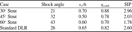
The expansion shock angles were determined from the contour diagrams of various strut geometries in order to offer quantitative insight into the shock–expansion interaction, as illustrated in Figure 8. The approximate expansion shock angles are 21° for the 30° strut, 32° for the 45° strut, 43° for the 60° strut and 26° for the standard DLR configuration. The results suggest that the expansion region becomes more pronounced as the strut angle increases, resulting in stronger expansion shocks and enhanced downstream flow divergence. Additionally, the shock reflection concentration region was identified between x = 140–160 mm, where a convergence of multiple reflected shocks was observed. This localised region of intensified pressure gradients contributes to the enhanced mingling of the fuel and air by promoting increased shear layer deformation and turbulence generation. In contrast, the standard DLR geometry demonstrates a more symmetric and moderate expansion pattern, as well as a relatively uniform shock distribution, which leads to a more stable but less vigorous mingling.
Velocity streamlines and the path lines near the strut region.

A normalised recirculation length (xr/h) is calculated for different strut configurations based on the recirculation length (xr) and combustion chamber height (h). These are 0.70, 0.50, 0.60, 0.65 for 30o, 45o, 60o and 90o case strut, respectively. The results show that the shock angle increases with the strut base angle, indicating stronger flow compression and steeper oblique shock formation. However, the recirculation length behind the strut decreases with increasing shock angle, suggesting reduced residence time and weaker flow entrainment for higher-angle cases. Among all configurations, the 30° strut exhibits the longest normalised recirculation zone (xr/h = 0.70), which contributes to improved fuel–air mixing and combustion stability. The standard DLR configuration shows similar behaviour, whereas the 45° and 60° struts produce shorter, more confined recirculation regions due to stronger shock-induced flow separation.
4.3 Velocity streamline pattern
The velocity differential separating the air and fuel creates a shear mixing layer that divides the two flow streams. Inside the shear mixing layer, the flow becomes turbulent and forms spiral vortices which helps in the transport of heat and momentum. These vortices are only formed with the gases inside the shear mixing layer, in this case, the hydrogen is injected inside this shear mixing layer. A lack of air interaction with fuel leads to poor performance. Instead, the angled injections help the fuel to penetrate the shear mixing layer and mix with the air, then the air-fuel mixture forms the vortices and improves the mixing performance in this case. From Figure 9 it has been observed a clear difference between the vortices formed in the standard DLR model and the angled injection models. In angled injection models, the fuel along with the air mixture gets recirculated and improves the air-fuel mixing performance as observed in Figure 9. This shows that angled fuel injections help in better mixing performance.
4.4 Hydrogen and water mass fraction
Figures 10 and 11 represent the hydrogen and water mass fraction for four cases. In the standard DLR case, the hydrogen mass fraction is observed with spiral vortices, whereas there are no such kinds of vortices observed in angled base injections. As observed from velocity streamlines from Figure 9 there is no interaction of air into the shear mixing layer causing only hydrogen to form the vortices. In a 30-degree base angle case, the fuel interacts with the air, and the mixture of the air-fuel forms the vortices. This helps hydrogen to react with oxygen a bit earlier and produces water. This can be observed from Figures 10 and 11 where there is a lower mass fraction of hydrogen in the 30-degree base case rather than in other cases and a high mass fraction of water is observed.
Contours of H2 mass fraction.

Contours H2O mass fraction.

The quantitative representation of the hydrogen (H2) and the water (H2O) mass fractions are calculated and shown in Figure 12. The graphs plotted the mass fraction of the H2 and H2O mass fractions at various positions along the combustor as shown in Figure 12 at axial distances of 125mm, 140mm, 275mm and along the axial length at the centre line. The 30-degree case possesses an H2 mass fraction of 32%, 46% and 85% lower and higher H2O mass fraction of 7%, 19% and 5% compared to the standard DLR model at an axial distance of 125mm, 140mm and 275mm, respectively. These values at every position are shown in Figure 12 representing the 30-degree case as having better mixing performance as shown in Figure 17(a).
H2 and H2O mass fractions at X = 125mm, X = 140mm, X = 275mm, and Y = 25mm.

4.5 Turbulence and vorticity
Shock waves, injection of fuel and ignition all produce turbulence, which is essential for air-fuel blending and combustion performance. Turbulence calculations are essential for assessing the combustor’s performance. According to Equation (11), the turbulence intensity is calculated by dividing the mean velocity by the square root of the changing RMS velocity [Reference Ono, Furuichi and Tsuji36]. Where U* is the fluctuations of the mean root square of turbulent velocity, and U is the mean velocity. Figures 13 and 14 illustrate how the turbulence intensity and kinetic energy are computed and presented. The turbulence intensity contours are extracted and shown in Figure 13 and observed a high turbulence intensity in a 30-degree case compared to other models.
 \begin{align}Turbulnce\;Intensity\;\left( {TI} \right) = \;\frac{{{U^*}}}{U} \times 100\% \end{align}
Turbulent intensity (%) contours.

Turbulent Kinetic Energy (TKE) at X = 125mm, X = 140mm, X = 275mm, and Y = 25mm.

Similarly, turbulent kinetic energy (TKE) is primarily produced by ignition and heat release phenomena, and its size is proportional to the intensity of these events. Using Equation (12), the current work assesses the distribution of TKE within the scramjet combustor for the three scenarios shown in Figure 14. In this formulation, (rho) represents the fluid density, whereas (U*), (V*), and (W*) denotes the fluctuations of root mean square (RMS) velocity in the x, y and z-directions, respectively [Reference Ono, Furuichi and Tsuji36]. The TKE in a 30-degree case is 31%, 41% and 10% higher compared to the standard DLR model at the axial distance 125mm, 140mm and 275mm. This high turbulent kinetic energy represents the higher combustion performance in the 30-degree case.
 \begin{align}Turbulent\;Kinetic\;Energy\;\left( {TKE} \right) = \;\frac{1}{2}\;\rho \;{U^*}^{2\;}{V^*}^2\;{W^*}^2\end{align}
The vorticity magnitude contours for various strut base angles (30°, 45°, 60° and 90°) are displayed in Figure 15 to show the shear-layer evolution and flow structure around the strut. The distribution of vorticity sheds light on the formation and strength of the recirculation zones, which are essential for fuel-air mixing and combustor flame stabilisation.
Vorticity contours for different strut configurations.

Strong vorticity is seen in the wake region and in the shear layer close to the trailing edge for the 30° strut, suggesting the development of a sizable and stable recirculation zone. This facilitates effective mixing downstream and increases turbulent entrainment. Stronger shear but a shorter residence time for the mixing process is suggested by the 45° strut’s slightly more intense but spatially limited vorticity zone. Stronger shock interactions and higher flow turning result in a narrower and less ordered wake in the 60° instance, where the vorticity further concentrates close to the strut’s base. Lastly, the 90° design indicates a highly divided flow with suppressed mixing because of significant obstruction and reduced shear-layer entrainment. It exhibits considerable vorticity exclusively at the sharp leading and trailing corners with minimal downstream development. All things considered, the results show that the 30° strut creates the best vorticity field for efficient and long-lasting mixing in the combustor flow.
4.6 Temperature
Figure 16 depicts the temperature contours for the angled strut base and the typical DLR model. The 30-degree angled examples have a larger turbulence and H2O mass fraction, resulting in a maximum temperature of 2424 K, which is higher than the DLR model. The heat released during a chemical reaction is exactly proportional to the static temperature. This improves the entropy and total temperature of the combustor, indicating improved functionality. Figure 17 depicts the calculated and plotted quantitative values of combustor temperatures. The temperature in the 30-degree model is 37% higher at axial distances of 125mm and 140mm, and 7% higher at 275mm, compared to the conventional DLR model. Figure 17 depicts that heat emitted in the 30-degree instance is significantly superior to that of the conventional DLR model and other models.
Temperature contours.

4.7 Performance parameters
The performance parameters determine the effectiveness of the supersonic engine through the capability of air-fuel mixing and combustion proficiency. The mixing quality is the capability of the fuel getting mixed in the air [Reference Li, Huang, Yan, Du and Fang26]. The mixing efficiency is obtained by comparing the blended fuel mass flow rate to the mass flow rate of the fuel present at the instance. The formulae of mixing efficiency as shown in Equation (13), where the
 ${{{\dot{\rm m}}}_{{{\rm{H}}_{2\left( {{\rm{inj}}} \right)}}}}$
is the mass flow rate of hydrogen from the injector, and
 ${{{\dot {\textrm{m}}}}_{{{\rm{H}}_{2\left( {\rm{x}} \right)}}}}$
is the hydrogen flow rate at the instance location.
 \begin{align}\unicode{x03B7}_{\rm{m}} = \frac{{\mathop\smallint\nolimits_{\rm{A}}} \unicode{x03B1}\unicode{x03C1}_{\rm{gas}}{\rm{Y}}_{\rm{H}_{2}}\rm{udA}}{{{\dot{\rm m}}_{\rm{H}_{2}}}} = \frac{{{\dot{\rm m}}_{\rm{H}_{2\rm{(inj)}}}}- {{\dot{\rm m}}_{\rm{H}_{2\rm{(x)}}}}}{{{\dot{\rm m}}_{\rm{H}_{2\rm{(x)}}}}}, with\;\unicode{x03B1} = \left\{ \begin{array}{cc}1, & \emptyset \lt 1\\1/\emptyset , & \emptyset \leq 1\end{array}\right\}\end{align}
Similarly, combustion efficiency is also known as the capability of fuel to get burnt and produce the reactants. The combustion capability is measured by the flow rate of the missing hydrogen from the injector to the flow rate of the hydrogen at the injection. The formulae of combustion efficiency as shown in Equation (14), where the
 ${{{{{\dot{\rm m}}}}_{{{\rm{H}}_{2\left( {{\rm{inj}}} \right)}}}}}$
is the hydrogen mass flow rate from the injector, and
 ${{{{{\dot{\rm m}}}}_{{{\rm{H}}_{2\left( {\rm{x}} \right)}}}}}$
is the hydrogen quantity at the instance location.
 \begin{align}{\unicode{x03B7}_{{\rm{comb}}}}\left( {\rm{x}} \right) = {\rm{\;}}1 - {{\smallint \left( {{\rm{A}}\left( {\rm{x}} \right)} \right){\unicode{x03C1}_{{\rm{gas}}}}{\rm{u}}{{\rm{Y}}_{{{\rm{H}}_2}}}{\rm{dA}}} \over {{{{{\dot{\rm m}}}}_{{{{{\dot{\rm H}}}}_{2({\rm{inj}})}}}}}} = {{{{{{\dot {\rm m}}}}_{{{\rm{H}}_{2\left( {{\rm{inj}}} \right)}}}} - {{{{\dot{\rm m}}}}_{{{\rm{H}}_{2\left( {\rm{x}} \right)}}}}} \over {{{{{\dot{\rm m}}}}_{{{\rm{H}}_{2\left( {{\rm{inj}}} \right)}}}}}}\end{align}
The mixing and combustion proficiency along the axial distance of the combustor are calculated and plotted as described in Figure 18. The mixing efficiency of the 30-degree case reaches 100% at a length of 160mm, which is 37% less than the standard DLR model from 220mm as depicted in Figure 18(a). eventually, the combustion efficiency of the 30-degree case reaches up to 97% as the standard DLR model reaches the ultimate combustion efficiency of up to 74%, where the 30-degree model performs 23% better than the standard DLR model as shown in Figure 17(b).
Temperature profiles at X = 125mm, X = 140mm, X = 275mm, and Y = 25mm.

Mixing efficiency (a); combustion efficiency along the combustors (b).

A detailed flow analysis using density (Figure 8), velocity (Figure 9), turbulence intensity (Figure 13), vorticity contours (Figure 15), temperature (Figure 16) and efficiency distributions (Figure 18) reveals that the 30° strut achieves an optimal balance between aerodynamic compression, fuel-air mixing and total-pressure recovery due to its favourable interaction with the oblique shock structure and recirculating wake dynamics.
At a 30° base angle, the strut’s principal oblique shock impinges downstream at a moderate inclination, creating adequate pre-compression for ignition while avoiding excessive boundary-layer separation. This arrangement creates a broad and stable recirculation zone in the strut wake (Figure 9), increasing the residence period and turbulent mixing of the hydrogen jet with the incoming air. The moderate shock strength also reduces overall pressure loss and wall heat flux (Figures 13 and 16), resulting in steady combustion and a uniform temperature field. In contrast, the 45° and 60° struts produce more powerful shocks and separate quicker, resulting in increased drag, localised hot patches, and slower total-pressure recovery. As a result, as shown in Figure 18, the 30° example has the highest mixing and combustion efficiencies, demonstrating that the performance improvement is driven by fundamental flow physics rather than configuration-specific tailoring.
A non-dimensional strut interaction parameter (SIP) is introduced as a function of free stream Mach number (
 ${M_\infty })$
, shock angle (
 ${\theta _s})$
, strut drag coefficient (
 ${C_d})$
, normalised recirculation length (x
r
/h) and combustion efficiency (
 ${\eta _{comb}}$
) to generalise these findings, which couples geometric and flow parameters that regulate the shock–recirculation interaction:
 \begin{align} SIP = \;\frac{{{M_\infty }\tan {\theta _s}}}{{{C_d}}}\; \times \frac{{{x_r}}}{h}{\eta _{comb}}\end{align}
The 30° case (Table 2) achieves the highest SIP when the SIP is weighted by the recirculation length (a proxy for residence time and mingling opportunity) and the actual combustion efficiency. This is consistent with the figure-based observation that 30° results in the most desirable overall engine performance due to its increased combustion efficiency and larger, more stable recirculation zone.
Strut interaction parameter (SIP) for various cases

The proposed angled strut-base configuration addresses practical problems about structural integrity and thermal management in high-enthalpy operating environments. The inclination of the strut base changes the local flow field, resulting in increased heat flux around the leading edge and angled surfaces due to stronger shock interactions. However, when the flow downstream expands, stagnation pressure lowers, reducing the structure’s total thermal burden. Asymmetric heating on inclined surfaces may result in localised thermal stresses, which can be effectively alleviated by advanced cooling technologies such as regenerative fuel cooling, film cooling or transpiration cooling. Furthermore, using high-temperature alloys or ceramic matrix composites (CMCs) can increase thermal durability while retaining mechanical strength.
5.0 Conclusion
The RANS equation was used to solve the supersonic flow field in a scramjet combustor and evaluate the velocity, mass fractions, turbulence and temperature parameters. This study evaluated the scramjet combustor with wedge strut, namely the conventional DLR type with the change of changing the strut base angle to increase air-fuel mixing.
-
• Changing the strut base angle caused the turning point to move upstream, allowing the expansion wave to interact with the shear mixing layer.
-
• Angled fuel injection allows the fuel to interact with the air prior and recirculating the mixture behind the strut base, rather than just fuel as in the standard DLR model.
-
• This earliest fuel interaction with the air promotes greater air-fuel mixing, and the reaction occurs when reactants disappear and products appear, as seen in the hydrogen and water mass fraction.
-
• The 30-degree model exhibits more turbulence and temperature compared to the regular DLR model, which improves combustor performance.
-
• 30-degree variants provide 37% and 23% greater mixing and combustion efficiency than the normal DLR type, respectively.
These increased efficiencies, together with higher temperatures and turbulence, render the 30-degree model efficient and contribute to the reduction of combustor length.
Acknowledgement
This research work supported by DST, India with Grant No: SUR/2022/001902
Competing interests
The authors declared no potential competing interests about this research article.