1. INTRODUCTION
With the development of Global Navigation Satellite Systems (GNSS) (the Global Positioning System (GPS), Globalnaya Navigazionnaya Sputnikovaya Sistema (GLONASS), BeiDou (BDS) and Galileo) and the evolution of GNSS receivers, it is possible for the public to take advantage of the multi-GNSS configurations to enhance the geometric strength of the GNSS positioning model, and improve positioning speed, as well as the accuracy, reliability and availability of GNSS positioning (Montenbruck et al., Reference Montenbruck, Hauschild and Steigenberger2014; Odijk and Teunissen, Reference Odijk and Teunissen2013a; Reference Odijk and Teunissen2013b). However, for many low-cost receivers that can only receive code observations, how to improve positioning accuracy in complex environments is an urgent problem.
As a commonly used precise positioning technology, Double Differencing (DD) has proven its efficiency and reliability over the past few years. For DD positioning, there are two multi-GNSS combined models. One of them chooses the pivot satellites for each constellation while the other uses only one-pivot satellite for multi-GNSS positioning (Julien et al., Reference Julien, Alves, Cannon and Zhang2003). In this paper, the first one is called the intra-system model and the second one is called the inter-system model. It has been demonstrated that the positioning accuracy of the inter-system model is better than the intra-system model, especially in a complex environment where signals are easily blocked by high buildings or trees (Gao et al., Reference Gao, Gao, Pan, Meng and Xia2017a; Reference Gao, Meng, Gao, Pan and Wang2018). Typically, if only one satellite can be received for each system, it is not possible for the intra-system model to form double differences, while it is still possible for the inter-system model to achieve reliable positioning. The key of the inter-system model is to obtain high-precision Differential Inter-System Biases (DISBs).
Many scholars have studied the processing methods of DISBs in Code Division Multiple Access (CDMA) systems. Similar to the handling methods for many GNSS biases, we need to verify the short-term and long-term stability of these biases and find ways to eliminate the rank deficit of the equations (Zhang et al., Reference Zhang, Teunissen and Yuan2017; Reference Zhang, Teunissen, Yuan, Zhang and Li2019; Odijk and Teunissen, Reference Odijk and Teunissen2013a). The research results have shown that for tightly combined same frequency signals in CDMA systems, the code and phase DISBs between two systems can be cancelled out for baselines with the same receivers. For different receivers, although the DISBs cannot be eliminated, their time series characteristics are stable and therefore can be corrected in advance (Odijk and Teunissen, Reference Odijk and Teunissen2013a; Reference Odijk and Teunissen2013b; Odolinski et al., Reference Odolinski, Teunissen and Odijk2014; Reference Odolinski, Teunissen and Odijk2015; Odolinski and Teunissen, Reference Odolinski and Teunissen2016; Paziewski and Wielgosz, Reference Paziewski and Wielgosz2015). Using these characteristics, Tian et al. (Reference Tian, Ge, Neitzel and Zhu2017) proposed a GPS L1-Galileo E1 phase DISBs real-time estimation method based on particle filtering, in which the accuracy of the particle was qualified by the related fixing ratio. The improvement of Ambiguity Resolution (AR) and positioning accuracy with calibrated DISBs for short and long baseline RTK have been verified by many researchers (Nadarajah et al., Reference Nadarajah, Khodabandeh and Teunissen2015; Odijk et al., Reference Odijk, Nadarajah, Zaminpardaz and Teunissen2017; Paziewski and Wielgosz, Reference Paziewski and Wielgosz2017; Wu et al., Reference Wu, Zhang, Liu, Ni and Yu2017). Aiming at combining the different frequencies of CDMA systems, Gao et al. (Reference Gao, Gao, Pan, Meng and Xia2017a; Reference Gao, Meng, Gao, Pan and Wang2018) integrated GPS and BDS single-frequency Real Time Kinematic RTK positioning through real-time estimation of DISBs.
Unlike CDMA systems, the Inter-Frequency Bias (IFB) must be taken into consideration when utilising GLONASS for baseline double difference positioning (Kozlov et al., Reference Kozlov, Tkachenko and Tochilin2000, Geng et al., Reference Geng, Zhao, Shi and Liu2017). For the Inter-Frequency Code Biases (IFCBs), research results have indicated that IFCBs can even reach up to several metres (Yamada et al., Reference Yamada, Takasu, Kubo and Yasuda2010), moreover, IFCBs are dependent not merely on receiver types, but also on antenna types and firmware versions (Shi et al., Reference Shi, Yi, Song, Lou, Yao and Zhang2013, Chen et al., Reference Chen, Yuan, Ding, Zhang and Liu2017, Zhou et al., Reference Zhou, Dong, Ge, Li, Wickert and Schuh2018). In general, there are three strategies to handle the GLONASS IFCBs for GLONASS baseline processing. The first one is de-weighting the GLONASS code observations to avoid the effect of IFCBs (Cai and Gao, Reference Cai and Gao2009). The second one uses a linear model to perform a priori calibration of IFCBs (Al-Shaery et al., Reference Al-Shaery, Zhang and Rizos2013; Banville et al., Reference Banville, Collins and Lahaye2013; Liu et al., Reference Liu, Shu, Xu, Qian, Zhang and Zhang2017), and the third one uses a short baseline to generate an IFCB valuations lookup table, then correcting IFCBs using this table in advance (Yamada et al., Reference Yamada, Takasu, Kubo and Yasuda2010, Tian et al., Reference Tian, Ge, Neitzel and Zhu2017). However, to the best of the authors' knowledge, there is no published research investigating the best IFCBs handling approach in double difference positioning. In this paper, after studying the relationship between IFCBs and the GLONASS signal channel for double differencing, an IFCBs correction model and an inter-system code differencing model between GLONASS and GPS is proposed and the improvement of the positioning performance with the proposed model and its comparison with the classical differencing model is tested.
The rest of this paper is organised as follows: In Section 2, the relationship between GLONASS DD IFCBs and the GLONASS signal channel will be examined in detail. In Section 3, a GLONASS IFCBs correction model is presented. The stability of GLONASS Single Differencing (SD) IFCBs and the effectiveness of the GLONASS IFCBs correction model are also demonstrated in this part. In Section 4, the GPS + GLONASS code inter-system function model and the stochastic model is presented, the stability of GPS + GLONASS DISCBs is analysed and the improvement of inter-system differencing model to the intra-system differencing model with various simulated satellite visibilities is investigated. In Section 5 the research findings are summarised.
2. THE RELATIONSHIP BETWEEN GLONASS DD IFCBS AND CHANNEL NUMBERS
2.1. A model for analysis of the characteristics of GLONASS DD IFCBs
Considering the influence of GLONASS IFCBs, the general un-differenced GLONASS code observation models can be expressed as Equation (1) (Tian et al., Reference Tian, Liu, Ge and Neitzel2018):
 $$P_a^{R,q} =\rho _a^{R,q} +c\left( {t_a -t^{R,q}} \right)+I_a^{R,q} +T_a^{R,q} +d^{R,q}+d_a^R +IFCBs_a^{R,q} +\varepsilon _a^{R,q}$$
where P is code observation, R refers to GLONASS, a refers to the receiver, q is the index of GLONASS satellites and  $q=1, \; \ldots, \; m_{R} $ stands for the number of GLONASS satellites. ρ is the distance between satellite and receiver, c represents the speed of light in a vacuum, t a and t*,s are the clock offsets for the receiver and satellite, respectively, I and T correspond to the ionosphere and troposphere biases, respectively, d R, q refers to the satellite hardware bias of GLONASS and
 $d_{a}^{R}$ is the same part of the code hardware bias for all GLONASS satellites. IFCBs stands for the GLONASS inter frequency code bias and ε is the sum of multipath error and measurement noise that can be treated as white noise. The errors such as Earth tide, ocean loading, relativistic effects can be accurately modelled, so they are not included in Equation (1).
For GLONASS, the satellite clock offsets and the satellite hardware bias will be eliminated by the between-receiver SD. The differential troposphere and ionosphere errors can also be neglected for short-baseline positioning (Gao et al., Reference Gao, Gao and Pan2017b). However, the GLONASS IFCBs cannot be eliminated by the SD. Hence, the short baseline between-receiver SD observation equations for GLONASS can be expressed as:
 $$P_{ab}^{R,q} =\rho _{ab}^{R,q} -c\cdot t_{ab} +d_{ab}^R+IFCBs_{ab}^{R,q} +\varepsilon _{ab}^{R,q}$$
After that, we can obtain the classical GLONASS DD observations model as Equation (3):
 $$P_{ab}^{q_1 q_2} =\rho _{ab}^{q_1 q_2 }+IFCBs_{ab}^{R,q_1 q_2 } +\varepsilon _{ab}^{R,q_1 q_2}$$
In Equation (3) 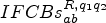 $IFCBs_{ab}^{R, q_{1} q_{2} } $ stands for the DD IFCBs and is composed of the inter-station SD IFCBs of satellites q1 and q2 and is related to the channel numbers. When a zero or short baseline is used to do the experiment, most of the atmospheric error interference can be reduced. In addition, when an International GNSS Service (IGS) site is used, because of the better observation environment, it can be considered that there is no multipath interference, therefore it can be considered that the DD residual bias mainly contains the IFCBs and observation noise. Using Equation (3), the DD IFCBs value (including observation noise) and the two channel numbers corresponding to it can be easily obtained so that the relationship between IFCBs and channel numbers can be analysed.
2.2. An experiment for analysis of the characteristics of GLONASS DD IFCBs
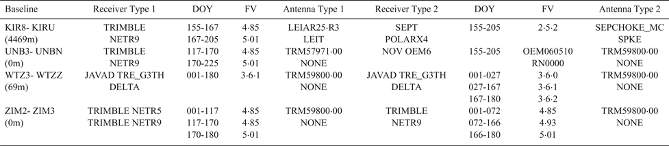
In order to analyse the relationship between GLONASS DD IFCBs and the channel number and test the improvement of the positioning accuracy from the inter-system differencing model to intra-system differencing model, four zero/short baselines observation data collected on DOY (Day Of Year) 150 in 2015, at sampling intervals of 30 s were selected from IGS sites, of which two baselines had different receiver types and two baselines had the same receiver types. Moreover, for the remaining experiments of this paper, in order to test the long-term variability of GLONASS SD IFCBS and GPS + GLONASS DISCBs, the data of the four baselines from DOY 001 to DOY 180 in 2015 were used. Table 1 shows the receiver types, firmware versions, antennae and other information of these baselines.
Information of the four baselines (FV in table stand for the firmware version of the receiver).

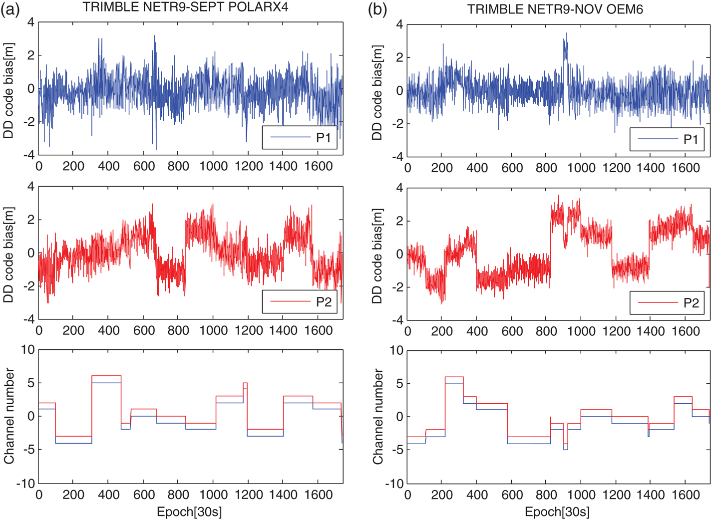
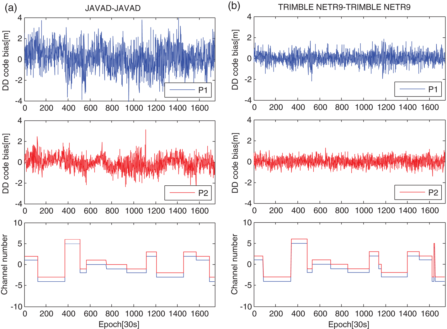
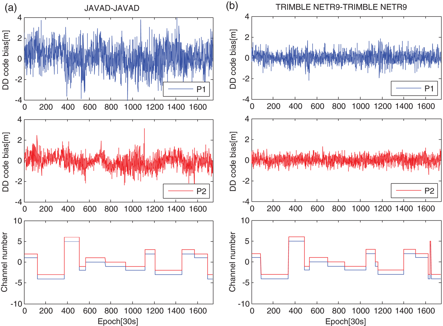
According to the simple deformation of Equation (3), the DD code residual bias including the IFCBs and the observation noise can be easily extracted. Figures 1 and 2 show the DD code residual bias of the above four baselines when the difference between the channel numbers is 1 on DOY 150, 2015. The corresponding two channel numbers are given at the same time. In theory, if the IFCBs does not exist, the mathematical expectation of DD code residual bias should be 0. As can be seen from Figures 1 and 2, for baselines (a), (b) and (c), the code residuals demonstrate non-white noise and the residuals between P1 and P2 are also different, indicating the existence of IFCBs on P1 and P2. For baseline (d), the residuals bias is very similar to white noise because the receivers of this baseline are from the same manufacturer. However, for baseline (c), although the receiver types are the same, the IFCBs still exist, which means that the IFCBs are different for some receivers even if the receiver types are the same. In addition, the IFCBs of P2 on baselines (a) and (b) show an obvious jump, and there exists a corresponding relationship between the IFCBs and the satellites pair, indicating that the IFCBs do not have a linear relationship with channel numbers in code DD relative positioning. In view of these properties, it is suggested that the SD IFCBs should be provided for each GLONASS satellite to obtain more precise DD positioning.
The DD code bias for two baselines with different receiver types (the difference of channel number is −1).

The DD code bias for two baselines with same receiver types (the difference of channel number is −1).
3. GLONASS IFCBS CORRECTION MODEL
3.1. GLONASS IFCB correction model
In order to eliminate the influence of IFCBs for the DD positioning model, the DD IFCBs in Section 2 are used to generate a SD-IFCB correction table. Assuming that the DD GLONASS IFCBs do not change within one day and they are modelled using SD IFCBs, the daily IFCBs estimation model for each satellite can be obtained. Unfortunately, the corresponding equation is one rank deficient. Considering that GLONASS has had a full constellation of 24 satellites since 8 December 2011 (Langley, Reference Langley2017), it can be assumed that the sum of all of the SD-IFCBs is equal to zero as Equation (4) expresses, thus the rank deficiency problem can be resolved and the SD-IFCBs can be determined (Shi et al., Reference Shi, Yi, Song, Lou, Yao and Zhang2013; Zhou et al., Reference Zhou, Dong, Ge, Li, Wickert and Schuh2018; Tian et al., Reference Tian, Liu, Ge and Neitzel2018).
 $$\sum_0^{24} IFCB_{ab}^q =0$$
3.2. Stability of GLONASS SD IFCBs
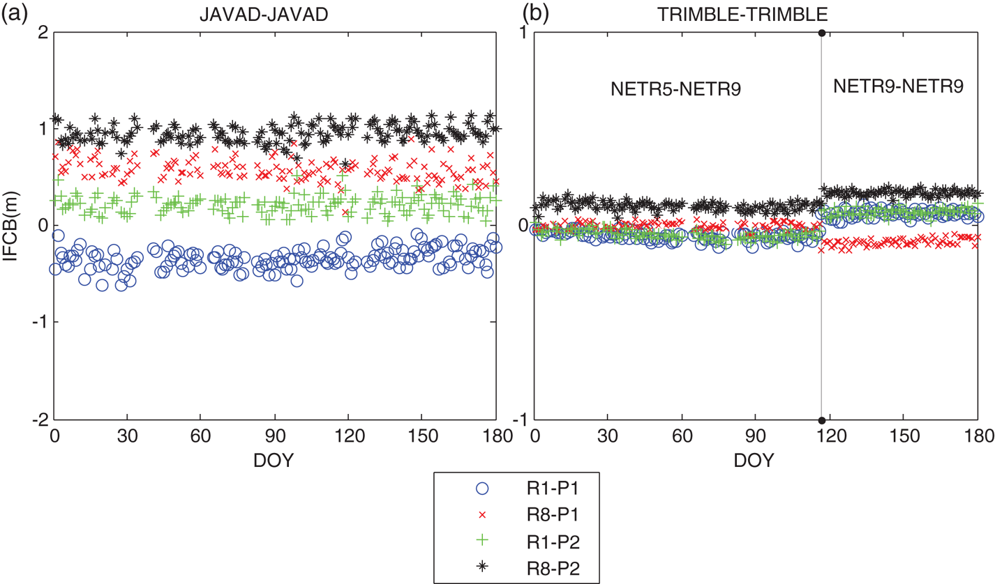
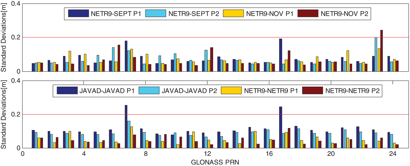
Figures 3 and 4 show the time series of IFCB valuations for the baselines with the same receiver types and the baselines consisting of different receiver types, respectively. These figures depict the change in IFCB valuations over time. The two charts clearly show that the IFCBs valuations of these four baselines are very stable from DOY 001 to 180 in 2015. It is worth noting that the jump in IFCB valuations in Figure 4(b) are due to the receiver type change of station ZIM2 on DOY 117 in 2015. According to Shi et al. (Reference Shi, Yi, Song, Lou, Yao and Zhang2013), when the firmware versions of Trimble NetR9 as well as JAVAD TRE_G3TH DELTA receivers changed, the IFCBs showed evident variations. However, in Figure 4, the change in IFCB valuations cannot be found even if the firmware versions are replaced (see Table 1). This might be due to the early firmware versions used in their research. To be on the safe side, the IFCBs should be re-estimated when firmware versions change. The standard deviations of the daily IFCBs estimates for each GLONASS satellite were also calculated. Figure 5 shows the standard deviations of IFCB valuations for these four baselines. It can be seen that the standard deviations of most satellites are less than 0·2 m. From the above experiments and analysis, it appears that the IFCBs estimates remained stable over time when the firmware version was not changed. Thus, the average IFCBs estimates can be considered as the final results for each baseline to generate correct tables to obtain more precise results.
The time-series of IFCBs for the two baselines with different receiver types.

The time-series of IFCBs for the two baselines with the same receiver types.

The standard deviations of IFCBs for each GLONASS satellite for two different receiver type groups (top) and two similar receiver type groups (bottom). The NETR9 represents TRIMBLE NETR9, the SEPT represents SEPT POLARX4, the NOV represents NOV OEM6 and JAVAD represents JAVAD TRE_G3TH DELTA.

3.3. Validation of IFCB correction model
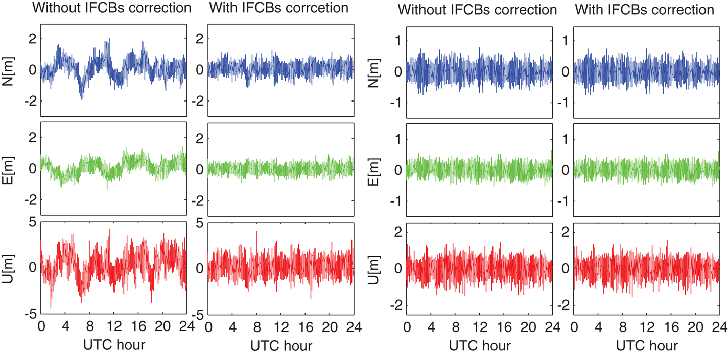
The positioning accuracy of the GLONASS intra-system code DD positioning model (as Equation (3) shows) before and after correcting the IFCBs are analysed in this section. Figure 6 shows the time-series of positioning errors for baselines KIR8- KIRU (TRIMBLE NETR9 - SEPT POLARX4) and ZIM2-ZIM3 (TRIMBLE NETR9 - TRIMBLE NETR9) with and without IFCB correction, and the statistics of positioning results are shown in Table 2. According to Figure 6 and Table 2, owing to the small IFCBs (see Figure 4(b)), the positioning accuracies of ZIM2-ZIM3 before and after IFCBs correction are the same. However, for the baseline KIR8- KIRU, as illustrated in Figure 6 (left), there are obvious systematic fluctuations in N/E/U directions if the IFCBs are ignored, while the influence of IFCBs are eliminated after IFCB calibration. Moreover, it can be seen from Table 2 (right) that compared with the model without IFCBs correction, the Root Mean Square (RMS) of KIR8- KIRU with IFCBs correction can be improved by 37·5% / 38·1% / 32·7% in N/E/U directions, respectively. This demonstrates that the IFCBs model used in this paper is correct and can be applied to GLONASS code relative positioning.
The time-series of positioning errors for baselines KIR8- KIRU (left) and ZIM2-ZIM3 (right).

Positioning accuracy for the intra-system model with and without IFCBs correction (RMS/m).

4. GPS + GLONASS CODE INTRA-SYSTEM MODEL AND INTER-SYSTEM MODEL
4.1. Function model
After revising IFCBs by using the IFCB correction table, the corresponding parameters in the SD model Equation (2) are eliminated. Therefore, the GLONASS SD model can be rewritten as follows:
 $$P_{ab}^{R,q} =\rho _{ab}^{R,q} -c\cdot t_{ab} +d_{ab}^R+\varepsilon _{ab}^{R,q}$$
Similarly, the between receiver SD model for GPS can be expressed as:
 $$P_{ab}^{G,s} =\rho _{ab}^{G,s} -c\cdot t_{ab} +d_{ab}^G +\varepsilon _{ab}^{G,s}$$
where G represents GPS, b refers to the rover receiver, s is the index of GPS satellites,  $s=1, \; \ldots, \; m_{G}$ stands for the number of GPS satellites and
 $d_{ab}^{G}$ is the code SD hardware bias for GPS satellites.
Afterward, the code intra-system model can be formed, where the receiver-dependent biases can be eliminated. Fixing q = 1R as a pivot satellite for GLONASS, the model can be expressed as:
 $$P_{ab}^{1_R q} =\rho _{ab}^{1_R q} +\varepsilon_{ab}^{R,1_R q}$$
Similarly, fixing s = 1G as a pivot satellite for GPS, the intra-system model for GPS can be expressed as:
 $$P_{ab}^{1_G s} =\rho _{ab}^{1_G s} +\varepsilon_{ab}^{G,1_G s}$$
Uniting Equation (5) and Equation (6), the GPS + GLONASS DD code inter-system model can be obtained as Equation (9), in which the receiver-dependent biases cannot be eliminated:
 $$P_{ab}^{1_G q} =\rho _{ab}^{1_G q} +d_{ab}^{GR}+\varepsilon$$
where:
 $$d_{ab}^{GR} =d_{ab}^R -d_{ab}^G$$
For the DISCBs  $d_{ab}^{GR}$ in Equation (9), it can be directly corrected if a priori DISCBs are known. Compared with the traditional intra-system model, the inter-system model will increase redundancy.
4.2. Stochastic model
For the inter-system model, because double differences are formed across two systems, when forming the stochastic model, the correlation between the observations from two systems should be accounted for, which is also different from the intra-system model. In order to get the stochastic model for these two models, first, based on the exponential elevation weighting function and the between-receiver SD operator, the covariance matrix Q SD of code observations in between-receiver SD can be obtained. Then the DD covariance matrix Q DD of code observations can be obtained by further applying the between-satellite SD operator D (Gao et al., Reference Gao, Meng, Gao, Pan and Wang2018):
 $$Q_{DD} =DQ_{SD} D^T$$
For the intra-system model, it can be expressed as:
 $$D=\left[ {{\begin{matrix} {D_{(m_G -1)\times m_G }^G } & {0_{(m_G -1)\times m_R } } \\ {0_{(m_R -1)\times m_G } } & {D_{(m_R -1)\times m_R }^R } \\ \end{matrix} }} \right]$$
While for the inter-system model, it can be expressed as:
 $$D=\left[ {{\begin{matrix} {D_{(m_G -1)\times m_G }^G } & {0_{(m_G -1)\times m_R } } \\ {D_{m_R \times m_G }^{GR} } & {I_{m_R } } \\ \end{matrix} }} \right]$$
 $$\begin{align} D_{(m_G -1)\times m_G }^G &=\left[ {-e_{m_G -1}, I_{m_G -1} } \right] \\ D_{(m_R -1)\times m_R }^R &=\left[ {-e_{m_R -1}, I_{m_R -1} } \right] \\ D_{m_R \times m_G }^{GR} &=\left[ {-e_{m_R }, 0_{m_R \times (m_G -1)} } \right] \end{align}$$
where 0m×n is the (m × n) matrix with all elements of 0; e m is the m-column vector with all elements of 1; I m is the (m × m) identity matrix. In this paper, the a priori zenith-referenced code precision (standard deviation) for undifferenced observations is set to 30 cm for both GPS and GLONASS.
4.3. Stability of GPS + GLONASS DISCBs
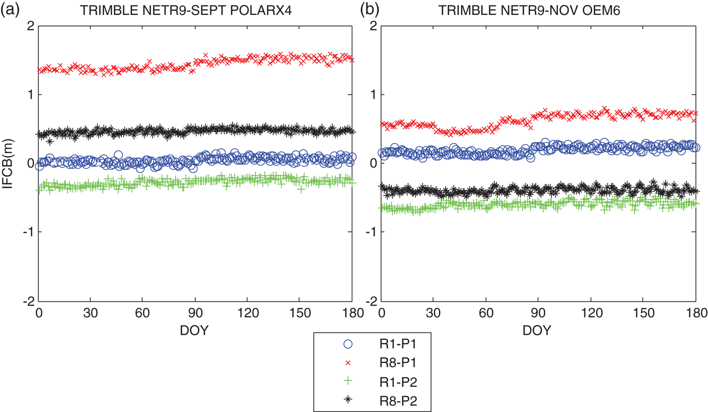
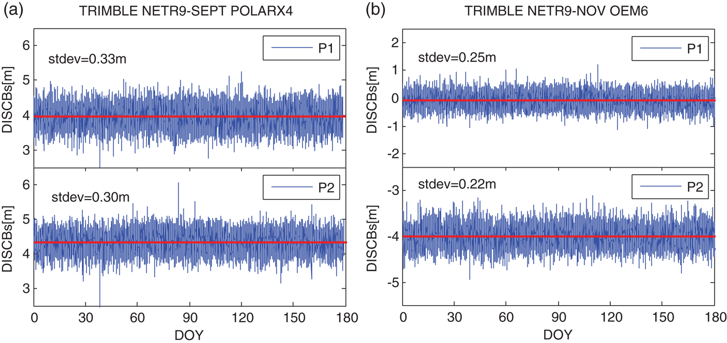
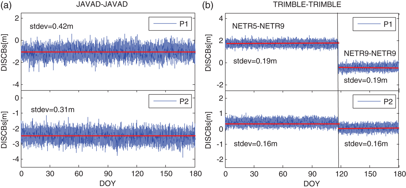
In order to test the variation of GPS + GLONASS DISCBs, the DISCBs of the four baselines from DOY 001, 2015 to DOY 180, 2015 have been calculated. Figure 7 depicts the DISCBs for the baselines with different receiver types, while Figure 8 shows the results for the baselines with the same receiver types. From Figure 7 and Figure 8, it can be found that: (1) The DISCBs on P1 and P2 are all different, especially from Figure 8 it can be seen that the DISCBs of different types of receivers produced by the same manufacturer are also different. (2) Even if the receiver types and the firmware versions are the same, the DISCBs between GPS + GLONASS are not zero, in contrast to the DISCBs among CDMA systems, just as earlier studies have shown (Gao et al., Reference Gao, Gao, Pan, Meng and Xia2017a; Reference Gao, Meng, Gao, Pan and Wang2018). (3) The DISCBs are very stable for the four baselines with the same receiver types or different receiver types, even when the firmware versions of the four baselines receivers changed (see Table 3). (4) The standard deviations (stdev) of the DISCBs for four baselines are all less than 0·45 m, regardless of the random terms caused by observation noises, it can be considered that the DISCBs for GPS + GLONASS are stable over a few days. Based on these characteristics, it is expected to increase the redundant observation information for DD code relative positioning and form the inter-system model.
DISCBs for the two baselines with different receiver types.
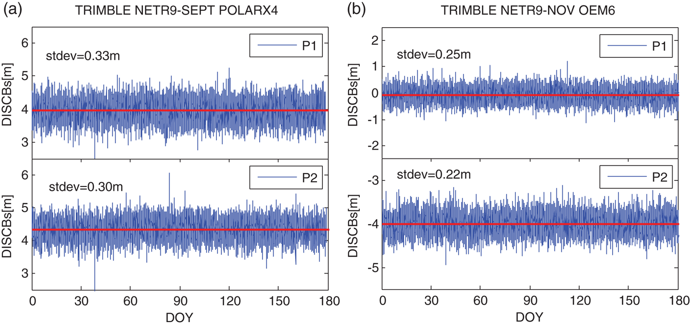
DISCBs for the two baselines with same receiver types.

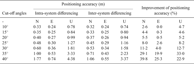
The statistics of positioning results and the improvement of the positioning accuracy from the inter-system differencing model to intra-system differencing model under different cut-off angles.

4.4. Contribution of inter-system differencing to positioning performance
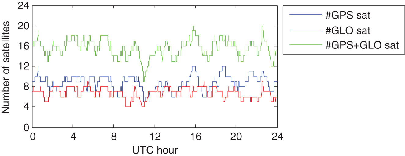
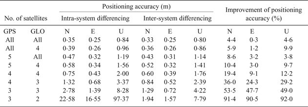
Theoretically, compared with the traditional intra-system differencing model, the inter-system model based on the DISCB correction can improve the strength of the positioning model, especially when only a few satellites are visible. In order to test the improvement of the positioning accuracy from the inter-system differencing model to the intra-system differencing model, the data of baseline KIR8-KIRU on DOY 150, 2015 were used to do the positioning experiment. To verify the performance of the two models in a complex environment, first the performance of the two models with cut-off angles from 10° to 40° was tested. Furthermore, to directly test the positioning performance with different visible satellites, a second experiment was carried out with several satellites from GPS and GLONASS; the number of visible GPS + GLONASS satellites with 15° cut-off elevation is shown in Figure 9. It can be seen that there were a minimum of four GLONASS satellites and a minimum of five GPS satellites, thus the satellites as shown in the left half of Table 4 were selected, and they were chosen in the descending order of elevations.
GPS + GLONASS satellite visibility for the baseline KIR8-KIRU with an elevation cut-off angle of 15°, from DOY 150 2015.

The statistics of positioning results and the improvement of the positioning accuracy from the inter-system differencing model to intra-system differencing model under different visible satellites.

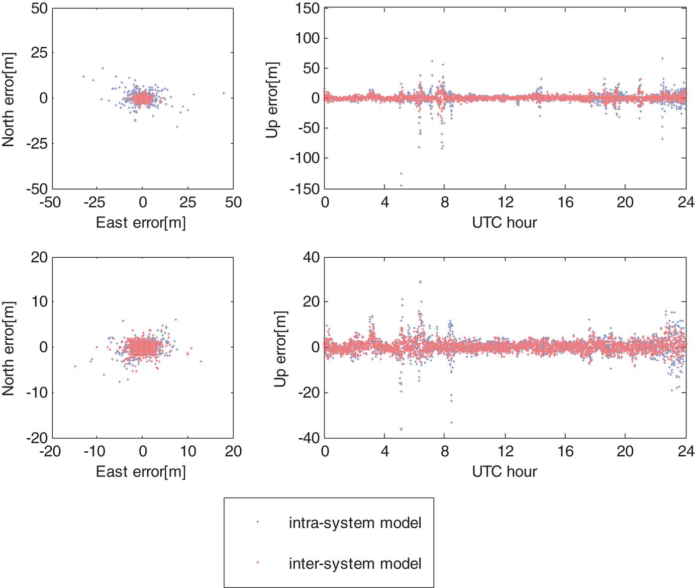
The statistics of positioning results and the improvement of the positioning accuracy from the intra-system differencing model to inter-system differencing model are presented in Tables 3 and 4. These positioning accuracies are obtained by comparing with the known baseline components. As can be seen from Tables 3 and 4, the positioning accuracy of the inter-system model is better than the intra-system model especially when only a small number of satellites is available, for example, when only three GPS and three GLONASS satellites were visible, the positioning accuracies improvements of the inter-system model reach up to 47·7%/53·5%/ 49·0% for the East/North/Up directions, respectively. As more and more satellites are visible, the positioning performance of the two models tends to be close, but the inter-system model is always slightly better than the intra-system model. In order to display the positioning performance of the two models more intuitively, the horizontal position scatter and corresponding vertical time-series for these two models are shown in Figure 10. It can be seen that the positioning error obtained by the inter-system model is more concentrated compared with the traditional one, indicating that the positioning accuracy of the inter-system model is better.
Horizontal (N, E) position scatter and corresponding vertical (U) time-series for intra-system model (blue dots) and inter-system model (red dots) with 3 GPS + 3 GLONASS (top) and 4 GPS + 3 GLONASS (bottom) visible satellites.

5. CONCLUSIONS
Inter-system code double differencing is an effective scheme to improve the positioning accuracy for low-cost receivers in complex environments. For GLONASS and GPS, the GLONASS IFCBs and the GPS + GLONASS DISCBs must be corrected in order to obtain GPS + GLONASS code-based DD inter-system positioning. In this contribution, after analysing the relationship between IFCBs and the GLONASS channel for double differencing, we proposed an IFCBs correction model and an inter-system code-differencing model between GLONASS and GPS. Finally, the performance of the inter-system positioning model was studied.
Based on the experimental results, it can be concluded that the IFCBs have no linear relationship with channel numbers and should be estimated for each GLONASS satellite. Moreover, although the IFCBs for the same or different receiver pairs are different, from the general point of view, the IFCBs are all stable over time and the standard deviations of IFCBs for most satellites are less than 0·2 m, and therefore the average IFCBs estimates can be considered as the final results for each baseline to generate a correction table to calibrate GLONASS inter frequency code bias. It can also be seen that even if the receiver types and the firmware versions are same, the DISCBs between GPS + GLONASS are nonzero, but the DISCBs are very stable as a whole for the four baselines and the standard deviations of DISCBs for four baselines are all less than 0·45 m. Regardless of the random terms caused by observation noise, it can be considered that the DISCBs for GPS + GLONASS are stable over a few days. With this feature, it is expected to increase the redundant observations information for DD code relative positioning.
Compared with the intra-system model, the GPS + GLONASS inter-system code differencing model can significantly improve the positioning accuracy in obstructed environments where only a small number of satellites are available. For example, when only three GPS + three GLONASS satellites are visible, the positioning accuracies improvement of the inter-system model in North/East/Up directions can reach up to 53·5% / 47·7% / 49·0%, respectively. As more and more satellites are visible, the positioning performance of the two models tends to be similar, but the inter-system model is always slightly better than the traditional model.
According to the research results of this paper, when a receiver pair is used for code relative positioning, IFCB and DISCB correction tables should be generated by using a short baseline first. After correcting the IFCBs and DISCBs, the receiver pair can obtain high code precision positioning whether it is a long baseline or short. Although only the GPS + GLONASS inter-system model was discussed in this paper, the method can be applicable to other code combination applications of CDMA systems to GLONASS.
ACKNOWLEDGEMENTS
This work is partially supported by the Primary Research & Development Plan of Jiangsu Province (No. BK20171353), the National Natural Science Foundation of China (No. 41574026, 41774027) and the Research and innovation program for graduate students in Jiangsu Province (No. KYCX17_0149). The authors gratefully acknowledge IGS for providing the GPS + GLONASS observation data. Thanks also go to the China Scholarship Council (CSC) for funding Rui Shang to study in the University of Nottingham for one year. We also thank all editors and reviewers for their valuable and constructive comments.