I. INTRODUCTION
Self-healing polymers provide an attractive materials platform to increase the service life of a polymer, improve their reliability, and increase damage resistance.Reference Blaiszik, Kramer, Olugebefola, Moore, Sottos and White1,Reference Binder2 In application areas where the service conditions are harsh, subjecting the material to repeated damage,Reference Blaiszik, Kramer, Olugebefola, Moore, Sottos and White1,Reference Sottos, White and Bond3–Reference Palleau, Reece, Desai, Smith and Dickey6 there is an urgent need to modify existing materials or develop new, low cost, and easy to manufacture materials that are capable of healing. A significant but little investigated application for self-healing is in wire insulation materials, especially in aerospace and automotive industries, where aggressive working conditions are the norm. According to US Naval Air Systems Command (NAVAIR), modern jets contain 100–200 miles of wiring, with 30% of aircraft having more than 70,000 flight hours, accumulating severe insulation damage.Reference Esser, Huston, Spencer, Burns and Kahn7–Reference Evans9 In these demanding applications, polymer insulation materials are exposed to continuous damage due to repeated mechanical damage, flexing, vibration, environmental factors, handling, etc. Wire cut through and chaffing account for almost 30–40% of wire failures on aircraftReference Evans9 and present a good opportunity for the use of new self-healing polymers. Significant drawbacks have been observed in the currently used polyimide (Kapton) and Polyvinyl chloride (PVC)-based insulation materials due to their non recyclable nature, problems with cracking and environmental toxicity. Polyethylene (PE) copolymers have been suggested as an eco-friendly alternative to these materials.Reference Ivanov, Migunova, Kalinina and Aleksandrov10 In this work, we report for the first time the development of self-healing ability of commercial PE copolymer ethylene-co-vinyl acetate (EVA) and study its ability to heal some of the common damage types seen in wire insulation. This is done by significantly improving and customizing the material system for use as wire insulation. The theoretical models measuring heating and self-healing used in Magpol can also be extended to other magnet–composite systems to increase the design based application area of this material system, for example, curing of epoxy or reflow of solder in microelectronic systems, etc.Reference Miller, Collier, Soll-Morris, Swaminathan and McHenry11–Reference Hubbard, Orange, Guinel, Guenthner, Mabry, Sahagun and Rinaldi14
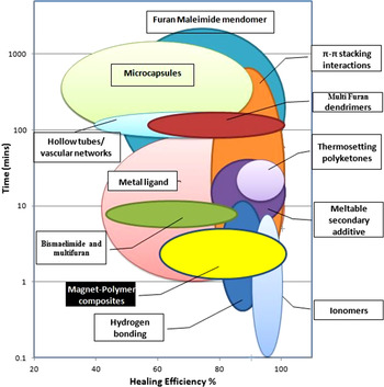
Several groups have developed strategies to incorporate self-healing polymers, with varying success, as compared in Fig. 1.Reference Blaiszik, Kramer, Olugebefola, Moore, Sottos and White1–Reference Sottos, White and Bond3,Reference Gragert, Schunack and Binder15–Reference Murphy and Wudl37 White et al.Reference White, Sottos, Geubelle, Moore, Kessler, Sriram, Brown and Viswanathan38 and Bond et al.Reference Trask, Williams and Bond16 integrated microcapsules and networks into polymers to develop composites capable of releasing healing agents into cracks or damaged areas through concurrent damage of healing containers. It must be noted that, in most cases, fastest healing occurs when an external stimulus is provided, especially heat. Other groups chemically designed new polymers capable of self-healing in response to external stimuli like heat, light, solvents, pH, etc.20s,Reference Wu, Meure and Solomon32 For example, Wudl et al. and several others designed a self-healing polymer based on the Diels–Alder (DA) reaction.Reference Rahmathullah and Palmese17,Reference Holten-Andersen, Harrington, Birkedal, Lee, Messersmith, Lee and Waite21,Reference Zhang, Broekhuis and Picchioni35,Reference Chen, Wudl, Mal, Shen and Nutt39,Reference Ax and Wenz40 Esser et al. used damage induced stiffening to minimize insulation damage caused by chaffing.Reference Esser, Huston, Spencer, Burns and Kahn7 While Parrish adapted the microcapsule-based method to develop self-healing wire insulation.Reference Parrish8 Unfortunately, the microcapsule-based methods are not well suited for insulating jackets due to the large capsule size and the difficulty in scaling up.
Overview of currently available self-healing polymers and composites based on their healing efficiency and time required for healing.Reference Blaiszik, Kramer, Olugebefola, Moore, Sottos and White1,Reference Sottos, White and Bond3,Reference Gragert, Schunack and Binder15–Reference Murphy and Wudl37

A promising wire insulation incorporating self-healing polymer could be developed using commercially available thermoplastic ionomers and their blends,Reference Kalista, Ward and Oyetunji34 which are capable of self-healing after high velocity impact (as indicated from Fig. 1). A significant drawback is that low velocity damage is not healed due to insubstantial temperature rise at the damage site. Hence, Duenas et al. suggested incorporating a magnetically responsive phase into the insulating polymer to cause localized heating by application of an external AC magnetic field.Reference Duenas, Andrew, Karen, Matt, Vishnu Baba, Fred, Erin, Ajit, James, Aaron and Teng41 While the concept of heating a polymer via embedded magnetic nanoparticles is not new, a significant drawback of this method is the sample deformation that occurs due to the high temperatures produced during heating, as well as the high filler loading required to achieve self-healing. This poses a significant problem as the healing does not offset the cost incurred due to the increased weight of the aircraft and has prevented further exploration into this methods' feasibility as a self-healing strategy.
To overcome the uncontrolled heating of the composite, we developed a novel strategy to increase the efficacy of magnetically induced heating by adding failsafe Curie temperature controlled nanoparticles for high temperature cut-off and optimized heating; while simultaneously using a high melt flow index EVA to prevent sample deformation. The presence of the magnetic filler enables uniform heating to be undertaken in situ, remotely, at greater penetration depths and also localizes the heating to only the damaged area, which overcomes a major obstacle in the current heat-gun methods used to repair damaged wire insulation. The Curie temperature regulation of heating also prevents pyrolysis of the polymer, increasing the number of repair cycles that the polymer can sustain.Reference Adzima, Kloxin and Bowman18
Corten and Urban,Reference Corten and Urban42 Duenas et al.,Reference Duenas, Andrew, Karen, Matt, Vishnu Baba, Fred, Erin, Ajit, James, Aaron and Teng41,Reference Duenas, Schlitter, Lacevic, Jha, Chai, Wudl, Westcott-Baker, Mal, Corder, Ooi and Proulx43 and Bowman et al.Reference Adzima, Kloxin and Bowman18 developed self-healing magnet–polymer composites for various applications. In each case, radio frequency AMF heating was used to achieve healing in the polymer matrix. Bowman et al.Reference Adzima, Kloxin and Bowman18 used a filler with a low Curie temperature to minimize pyrolysis. They used CrO2 with a T C of 113 °C to reverse the D–A linkages in their polymer matrix.Reference Adzima, Kloxin and Bowman18 The T C of CrO2 cannot be varied and is therefore unsuitable for materials with different processing temperatures. Other options include Ni and iron oxide particles, which have a high T C and have been shown to cause thermal degradation, pyrolysis, and distortion of the matrix over long periods of heating. Thus, there is a requirement for a magnet–polymer composite wherein the T C can be tuned depending upon the temperatures required for self-healing.
The Curie temperature of MnZn ferrites can be controlled by changing the ratio of the Mn content to the Zn content. Previous reports have shown that the Curie temperatures range from 560 K for Mn0.7Zn0.3Fe2O4 to 330 K for Mn0.3Zn0.7Fe2O4, depending on the synthesis conditions.Reference Feng, Guo, Xu, Qi and Zhang44,Reference Lan, Tien, Duong and Truong45 To obtain optimal healing, magnetic nanoparticles used as fillers in the polymer matrix can have their T C tuned to match the processing temperature of the polymer. At the processing temperature, fusion bonding or welding processes will occur according to the reptation theory, which states that, at any temperature above the glass transition temperature (T g), polymer chains will diffuse across an interface and entangle with each other to produce a bond. Healing between polymer chains at the interface is achieved by the following steps: surface rearrangement, surface approach, wetting, diffusion, and randomization.Reference Kim and Wool46 The process is temperature dependent and increasingly efficient at higher temperatures, which can be controlled by the T C of the filler.
In this work, the effect of different Curie temperature filler materials on the degree of healing, as well as the time taken to heal common types of EVA insulation damage was studied. Models to estimate temperature change and healing time were compared to experimental data. The T C of the filler could be tuned by adjusting the Mn:Zn ratio, while the final temperature of the composite depended on the loading. Factors influencing healing efficiency included the T C of the filler, loading of the particles, time of exposure to the AMF as well as volume of induced damage. We observed that composites containing higher T C fillers showed 100% healing in shorter times, while 20 min was enough to obtain complete healing in all cases studied. The maximum damage volume that resulted in complete healing was 10%, after which the healing efficiency decreased.
We show for the first time the difference in healing efficiency caused due to differing T C of the filler and eliminate the problem of sample deformation without affecting the loading capacity of Magpol. By using novel T C controlled fillers, the heating of the films could be localized and regulated to prevent damage to the polymer due to thermal degradation. High healing efficiency was also obtained at lower filler loading and shorter healing times compared to previous reports. The addition of magnetic filler can also be extended to other kinds of healing which require elevated temperatures,Reference Varley and Zwaag47 as well as impart additional functionality to the composite material, including electromagnetic shielding, improved mechanical properties, and the ability to actuate under a remotely applied magnetic field.
II. EXPERIMENTAL METHODS
A. Materials
All materials were used as received without further purification. Manganese(II) chloride tetrahydrate 99% (MnCl2•4H2O), anhydrous (98+%) zinc chloride (ZnCl2), iron(III) chloride hexahydrate, ACS (FeCl3•6H2O), and sodium hydroxide (NaOH) were purchased from Alfa Aesar. Poly(ethylene-co-acrylic acid) 15 wt%, 1,1,2,2-tetrachloroethane, and anhydrous 99% tetrahydrofuran were obtained from Sigma Aldrich. Polyethylene vinyl acetate of brand Cosmothene EVA KA-31 (28% VA content) and MilliQ water were used for all experiments.
B. MnxZn1−xFe2O4 nanoparticle synthesis
Nanoparticles were synthesized via the hydrothermal method. Manganese (MnCl2), zinc (ZnCl2), and iron chloride salts (FeCl3) were each dissolved separately in appropriate molar quantities of MilliQ water. NaOH (∼5 M) was added to the iron chloride solution until a pH value of 8 was reached. The obtained precipitate was centrifuged and washed thrice with MilliQ water before being added to the Mn and Zn salt solutions. The salt solutions were then added together in a beaker equipped with a mechanical stirrer and vigorously stirred while adding sodium hydroxide drop wise, until the reaction mixture reached a pH of 12. The resulting slurry was decanted into a pressure vessel and placed in an oven at 190 °C for 4 h. These particles were then washed several times with DI water and ethanol and then vacuum dried for further characterization. Samples were prepared with different Mn:Zn ratios, i.e., Mn0.9Zn0.1Fe2O4, Mn0.8Zn0.2Fe2O4, and Mn0.7Zn0.3Fe2O4 and will be henceforth referred to as Mn0.9, Mn0.8, and Mn0.7, respectively.
To prevent particle agglomeration during processing of the composite, the Mn–Zn ferrite particles were coated with poly(ethylene-co-acrylic acid). The nanoparticle slurry obtained after hydrothermal synthesis was washed in tetrahydrofuran (THF). Poly (ethylene-co-acrylic acid) (PEAA) (40 mg/mL) in a 1:1 wt/wt ratio to the nanoparticles was added to the slurry in THF. The solution was then ultrasonicated for 6–8 h. in an ultrasonic bath. The solution was then allowed to stand for 12 h and the stable non-settling solution was removed. The stable particles were then magnetically separated and washed with THF to remove excess PEAA.
C. EVA composite synthesis
EVA–magnetic particle composites were prepared by solution casting for ease of testing. For solution casting, the polymer pellets were dissolved in 1,1,2,2-tetrachloroethane (TCE) at ∼120 °C. The appropriate amount of nanoparticles was then added to the solution, which was then immediately cast into petri dishes in an oven at 120 °C. The TCE was allowed to evaporate for 4 h and the films were slowly cooled to room temperature. The resulting films were then peeled off and placed in a vacuum oven at room temperature for a minimum of 24 h to ensure complete solvent removal. The films obtained through this solution casting method were ∼150 µm thick. Composite films containing 10, 12, and 16 wt% of Mn0.9, Mn0.8, and Mn0.7 nanoparticles were cast for further study.
D. Characterization
The structure and composition of the Mn–Zn ferrites were studied by a Shimadzu 6000 x-ray diffractometer (XRD; Tokyo, Japan) with Cu Kα radiation of wave length 1.54056 Å, in the 2θ range of 20–80° at a scan rate of 2° min−1. Phase identification was performed by matching peak positions and relative intensities to reference JCPDS files. The crystallite size was calculated using the Scherrer formula. The magnetic properties of the materials were determined using a Lakeshore 7404 vibrating sample magnetometer (VSM) in an applied field range of 0–10 kOe. Curie temperature measurements were conducted by measuring the magnetization at 500 Oe from 295 to 773 K.
The particle size and morphology of the synthesized nanosize particles were characterized by a JEOL 2010 transmission electron microscope (Peabody, MA) operating at 200 kV. Particle size was measured from transmission electron micrographs using ImageJ image processing software.
Thermogravimetric analysis was done using a TA2950 Thermal Gravimetric Analyzer (TGA), up to a maximum temperature of 650 °C and heating rate of 10 °C/min under a dry nitrogen atmosphere.
E. Measurement of healing efficiency
To simulate the cut-through and elongation damage in wire insulation, the composite was damaged by subjecting it to a trouser tear test conducted according to ASTM standard D1938-08 using an Instron 5567 mechanical tester with a crosshead speed of 50 mm/min. The torn edges are then held together and sandwiched between two glass slides. The slides are then placed within a water-cooled five-loop copper induction coil energized by an AC generator (Inductelec, UK) with an operating frequency of 475 kHz and field strength of 4 kA m−1 for time intervals ranging from 5 to 30 min. The samples were then removed and subjected to a second tear test to measure recovery. The maximum tear strength was measured for both virgin and healed samples. The efficiency of healing was calculated by the formula
 $$\% {\rm{Healing}}\;{\rm{Efficiency}} =\; \left[ {{{{\rm{Max}}{\rm{.\ Tear\ strength}}\;({\rm{Healed}})} \mathord{\left/ {\vphantom {{{\rm{Max}}{\rm{.\ Tear\ strength}}\;({\rm{virgin}})} {{\rm{Max}}{\rm{.\ Tear\ strength}}\;({\rm{Healed}})}}} \right. \kern-\nulldelimiterspace} {{\rm{Max}}{\rm{.\ Tear\ strength}}\;({\rm{virgin}})}}} \right] \times 100\quad {\rm{.}}$$
The ability of Magpol to recover from chaffing damage was investigated by studying the tribological performance of the samples slid against a steel ball (Cr6) of 6 mm in diameter for about 150 m in sliding distance under a normal load of 2 N, using a ball-on-disk tribometer (CSEM 15-208) at room temperature (22 °C). The sliding circular path and velocity used for all the tribological tests were 2 mm in radius and 5 cm/s, respectively.
Film temperature was continuously logged using a Luxtron MD600 fiber optic thermometry unit. Optical assessment of the healing was performed by making a razorblade cut through the sample and subjecting it to a RF field. Healing was observed under a SEM (JEOL 5310, Peabody, MA) microscope operating at 5 kV.
III. MODELING OF POWER OUTPUT, FILM HEATING, AND HEALING EFFICIENCY
Heat generation from a magnetic nanoparticle exposed to an alternating magnetic field (AMF) occurs primarily due to relaxation losses. To calculate the magnitude of heat generated by the magnetic particles, we use the model proposed by Rosensweig. We consider only Neel relaxation, as the particles are embedded in a polymer film of high viscosity, causing the Brownian relaxation times to be almost equal to the time scale of the experimentReference Rosensweig48,Reference Purushotham and Ramanujan49 (Supplementary Information). Accordingly, the volumetric power dissipation (P) from the particles is calculated by the formula given by Eq. (1)
 $$P = \pi {\mu _0}{\chi _0}\mathop {{H_0}}\nolimits^2 f{{2\pi f\tau } \over {1 + {{\left( {2\pi f\tau } \right)}^2}}}\quad {\rm{,}}$$
where μ0 is the permeability of free space, H 0 is the AMF strength, f is the field frequency, and χ0 is the particle equilibrium susceptibility, which can be calculated according to the Langevin equation [Eq. (2)].
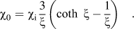 $${\chi _0} = {\chi _{\rm{i}}}{3 \over \xi }\left( {\coth \;\xi - {1 \over \xi }} \right)\quad {\rm{.}}$$
and initial susceptibility χi can be derived from Eq. (3)
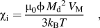 $${\chi _{\rm{i}}} = {{{\mu _0}\phi \mathop {{M_{\rm{d}}}}\nolimits^2 {V_{\rm{M}}}} \over {3{k_{\rm{B}}}T}}\quad {\rm{,}}$$
where φ is the volume fraction of nanoparticles in the polymer film and M d is the domain magnetization of the nanoparticle. k B is the Boltzmann's constant. The Langevin function parameter, ξ, can be calculated from Eq. (4)
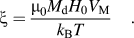 $$\xi = {{{\mu _0}{M_{\rm{d}}}{H_0}{V_{\rm{M}}}} \over {{k_{\rm{B}}}T}}\quad {\rm{.}}$$
The Neel relaxation time can be calculated by the expression in Eq. (5)
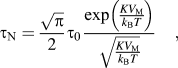 $${\tau _{\rm{N}}} = {{\sqrt \pi } \over 2}{\tau _0}{{\exp \left( {{{K{V_{\rm{M}}}} \over {{k_{\rm{B}}}T}}} \right)} \over {\sqrt {{{K{V_{\rm{M}}}} \over {{k_{\rm{B}}}T}}} }}\quad {\rm{,}}$$
where V M is the magnetic volume and K is the anisotropy constant for the magnetic nanoparticles. τ0 is ∼10−9 s.
Based on the power output from the nanoparticles embedded in Magpol, the temperature rise of Magpol over time was calculated. By using time dependent heat transfer in solid model from COMSOL Multiphysics 4.3b software using a cylindrical coordinate system (r, θ), the temperature versus time relationship can be derived through Eq. (6)Reference Levine, Zvi, Winkler, Schmidt and Gottlieb50
 $$\rho {C_{\rm{p}}}{{\partial T} \over {\partial t}} + \rho {C_{\rm{p}}}{\rm{u}} \cdot \nabla T = \nabla \cdot (k\nabla T + Q)\quad {\rm{,}}$$
where ρ is the density, k is the thermal conductivity, C p is the heat capacity of the polymer, and Q is the volumetric power output from the magnetic nanoparticles as calculated in Eq. (1). Initial conditions (IC) and boundary conditions (BC) were set as follows:
 $${\rm{I}}{\rm{.C}}{\rm{.}}1\;T(r,0) = {T_{\rm{a}}}\quad {\rm{,}}$$
 $${\rm{I}}{\rm{.C}}{\rm{.}}2\;T(r,\infty ) = {T_{\max ({\rm{S}})}}\quad {\rm{,}}$$
 $${\rm{B}}{\rm{.C}}{\rm{.}}\;r = {\rm{S}}, - n \cdot \left( { - k\nabla T} \right) = h \cdot \left( {{T_{{\rm{ext}}}} - T} \right)\quad {\rm{,}}$$
where T a is the surrounding air temperature, T max(S) is the equilibrium temperature at the surface (S) of the film, T ext is the surface temperature, and h is the heat transfer coefficient.
The healing behavior of the composite was calculated using models developed by Bastien and Gillespie,Reference Bastien and Gillespie51 Sonmez and Hahn,Reference Sonmez and Hahn52 and Yang and PitchumaniReference Yang and Pitchumani53 based on reptation theory. This theory assumes that intimate contact has been achieved between the two faces of the damaged polymer. In this model, a polymer chain of length L is assumed to be confined to a tube. Within a certain time t, the chain moves within the tube in a manner similar to Brownian motion and a part will eventually escape the tube as a minor chain. As time proceeds, the minor chain will grow and move across the interface to interpenetrate with chains on the other side. The bond strength and therefore degree of healing are proportional to the interpenetration distance of the minor chain. This degree of healing, i.e., the ratio of the instantaneous interfacial bond strength to the ultimate bond strength, as determined by Yang and Pitchumani is given by Eq. (7)
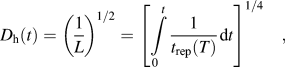 $${D_{\rm{h}}}\left( t \right) = {\left( {{1 \over L}} \right)^{1/2}} = {\left[ {\mathop \smallint \int\limits_0^t {1 \over {{t_{{\rm{rep}}}}\left( T \right)}}{\mathop{\rm d}\nolimits} t} \right]^{1/4}}\quad {\rm{,}}$$
where t rep is the reptation time of the polymer at a given temperature. The reptation time of the polymer can also be calculated by taking into consideration interactions between the polymer chains and the nanoparticle filler. Using the method developed by Rubinstein et al.Reference Zheng, Sauer, Van Alsten, Schwarz, Rafailovich, Sokolov and Rubinstein54 and Kalfus and Jancar,Reference Kalfus and Jancar55 the reptation time t rep of the polymer chains in the composite is given by Eq. (8)
 $${t_{{\rm{rep}}}} = {{{b^2}{N^{5/2}}} \over {2{\pi ^2}{k_{\rm{B}}}T{N_{\rm{e}}}}}\left[ {{\xi _0}{N^{1/2}} + {\xi _{\rm{a}}}} \right]\quad {\rm{,}}$$
where ξ0 is the monomer friction coefficient, ξa is the friction coefficient of a monomer absorbed onto a filler particle, b is the length of a statistical segment, T is the temperature, N is the number of monomer units in a chain, and N e is the number of monomer units per entanglement strand. We assume that the polymer is composed entirely of vinyl acetate.
ξa can be calculated based on the theoretical model given by Subbotin et al.Reference Subbotin, Semenov and Doi56 [Eq. (9)],
 $${\xi _{\rm{a}}} = {{{k_{\rm{B}}}T\tau } \over {{b^2}}}\quad {\rm{,}}$$
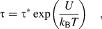 $$\tau = {\tau ^*}\exp \left( {{U \over {{k_{\rm{B}}}T}}} \right)\quad {\rm{,}}$$
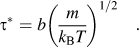 $${\tau ^*} = b{\left( {{m \over {{k_{\rm{B}}}T}}} \right)^{1/2}}\quad {\rm{.}}$$
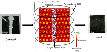
where m is the weight of one monomer unit and U is the activation energy. Figure 2 illustrates the processes occurring during healing as described above. Upon exposure to the AMF, the nanoparticles embedded in the composite heat up to a maximum temperature, as determined by their Curie temperature. This heat is transferred to the surrounding polymer matrix and the temperature of the entire composite reaches equilibrium with the surrounding. The increased temperature promotes chain movement across the damaged regions of the two interfaces, ultimately resulting in complete entanglement of the chains at the interface and healing of the damaged regions.
Illustration of particle heating leading to film heating and subsequent polymer chain entanglement, resulting in healing when the damaged composite is exposed to an AMF.

IV. RESULTS AND DISCUSSION
A. Characterization
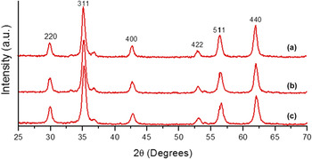
The XRD patterns of the synthesized ferrites are shown in Fig. 3, indicating the characteristic peaks of cubic spinel structure. The 2θ peaks at 29.9, 35.2, 42.6, 52.9, 56.3, and 61.9° match the experimental data for the franklinite spinel structure (JCPDS card No. 10-0467), indicating the presence of MnxZn1−xFe2O4 in all the samples. Small differences between the 2θ values denote differences in the unit cell parameters. Minor peaks are also seen at 2θ values of 33.15, 35.61, 40.85, 49.48, 54.09, and 63.99° that can be fitted to JCPDS card No. 33-0664, indicating the presence of hematite (α-Fe2O3). This may be due to dissolution and reprecipitation of the iron hydroxide during the hydrothermal treatment.
XRD patterns of Mn–Zn ferrites (a) Mn0.9, (b) Mn0.8, and (c) Mn0.7.

The Scherrer equation was used to calculate the average crystallite diameter. Since most samples contained small mass fractions of α-Fe2O3, which has peaks close to the 35.2° and the 42.8° peaks of the spinel, the results obtained from the calculation based on the 29.78° peak are considered to be more accurate. Increasing Mn content resulted in an increase in crystallite size. The average size of the Mn0.7 nanoparticles is 12.4 nm, for Mn0.8 it is 13.2 nm, and it is 15 nm for Mn0.9 nanoparticles. This increase in size is due to strong chemical affinity of Zn2+ cations for the tetrahedral sites of the spinel lattice.
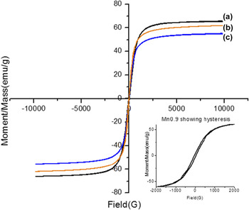
The room temperature hysteresis curves of the magnetic nanoparticles are shown in Fig. 4. The saturation magnetization increases with Mn content from 55 emu/g for Mn0.7 to 62 emu/g for Mn0.8 and 65 emu/g for Mn0.9. This is due to an increase in magnetic moment of the tetrahedrally coordinated ions in the sublattice. A sigmoidal anhysteric magnetization curve is observed for Mn0.7 and Mn0.8 samples, but due to size distribution and clustering effects the experimental magnetization curves display a small amount of hysteresis. The larger hysteresis loop observed in the Mn0.9 sample can be caused by the larger particle size, shifting these particles from the superparamagnetic to the ferromagnetic domain region.
Room temperature VSM measurements of (a) Mn0.9, (b) Mn0.8, and (c) Mn0.7.

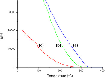
A magnetization versus temperature M–T curve was also plotted for all the samples to determine the Curie temperature of the samples. No sharp transition temperature was observed in these samples. In such cases, it has been observed that spontaneous magnetization (Ms) scales as (T C–T)β with a critical exponent β = 1/3. Therefore, the Curie temperature is determined by extrapolating M 3 to 0 (Fig. 5).Reference McNerny, Kim, Laughlin and McHenry57 The T C increased with increasing Mn content. The T C of Mn0.9 sample was 280 °C, while Mn0.8 had a T C of 230 °C and the Mn0.7 sample had the lowest T C of 190 °C. The decrease in the nonmagnetic Zn ions as well as strengthening of A–B interactions in the tetrahedral sites is responsible for an increase in T C with increasing Mn content.
Magnetization versus temperature curves for (a) Mn0.9, (b) Mn0.8, and (c) Mn0.7.

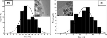
The samples were also observed under TEM to determine their size and structure. Figure 6 shows a TEM micrograph of Mn0.7 and Mn0.8 nanoparticles. The average particle size of 12.5 and 13.6 nm, respectively, is reasonably close to the values obtained through XRD data. The observed aggregation is due to attractive magnetic forces between the particles and the absence of a surfactant layer. Mn0.7 particles show a narrower size distribution, with particle sizes ranging from 9 to 18 nm. The Mn0.8 particles have a slightly wider distribution with sizes ranging from 9 to 19 nm.
Particle size distribution and bright-field transmission electron micrograph of (a) Mn0.7 and (b) Mn0.8 nanoparticles.

B. Healing efficiency
As the films cast using the Mn0.9 nanoparticles were inhomogenous and had visible aggregates, they were not considered for further study (data not shown). Heat generated by the particles in the film would be spread unevenly, resulting in hotspots and cold regions. Mn0.7 and Mn0.8 containing films did not have any visible aggregates under an optical microscope. While the particle distribution is homogenous on the macro scale, resulting in even heating along the entire sample, it is possible that nanoscale aggregates form during PEAA coating. This could be due to multiple nanoparticles being coated by PEAA during the stabilization process. SEM images show small aggregates of up to 5 micrometers on the film surface, while the larger features are caused due to the solution casting process and irregularities of the mold surface.
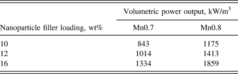
Heat generated by the particles was calculated via Rosensweig's model.Reference Rosensweig48Table I tabulates the volumetric power output for Mn0.7 and Mn0.8 for each filler loading of 10%, 12%, and 16 wt%.
Volumetric power output of the composite films based on loading and filler type.
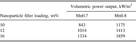
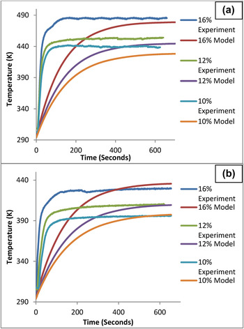
Based on this power output, the temperature change in Magpol was also measured. Figure 7 shows the measured as well as theoretically determined temperature rise over the film surface when subjected to an AMF. The experimental temperature rise is slightly faster than the model, while the cutoff is sharper, indicating T C controlled regulation of heating rather than merely heat loss to the surroundings. The Mn0.8 films with higher T C exhibit higher temperatures compared to Mn0.7. The loading can also affect the final temperature of the film. Higher loading will increase the final film temperature, but interestingly, only up to a maximum temperature which will coincide with the T C of the filler particles. Thus, the heating of the films can be regulated to prevent damage to the polymer due to high temperatures. The temperatures obtained for all the Mn0.8 films and the 16 wt% loading Mn0.7 films lie between 150 and 220 °C, which is the average processing temperature for EVA.
Experimental and predicted temperature rise of Magpol containing (a) Mn0.8 and (b) Mn0.7 nanoparticle fillers at different loadings.

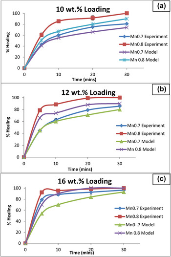
The composite films were then subjected to the tear test, which simulates notch damage or cut through, which can occur during wire installation or during service. Subsequent healing of the AMF for different time intervals (5–30 min) was recorded. Figure 8 shows the extent of healing for each wt% loading, i.e., 10, 12, and 16 wt% for both the Mn0.8 and Mn0.7 filler compositions.
Experimental and predicted healing of films containing different nanoparticle loadings over time. (a) 10 wt%, (b) 12 wt%, and (c) 16 wt%.

As predicted by reptation theory,Reference Bastien and Gillespie51 the interfacial temperature greatly influenced the final healing. Higher film temperatures show better healing in less time. The initial time period from 0 to 5 min shows relatively rapid healing. This can be explained by the steps involved in bond formation at the interface.Reference Zhang and Rong58 Initially, surface rearrangement, surface approach, and wetting occur. The initial time period was sufficient for these processes to occur and provide limited strength to the interfacial bond. The later steps of diffusion and randomization are time dependent and required for the damaged section to regain its original properties. The films containing Mn0.7 particles as the filler did not show 100% healing even after 30 min as the maximum temperature reached was insufficient to produce sufficient chain motion for complete entanglement to occur in. Interestingly, the Mn0.8 filler films showed 100% healing in every case when the time of application of the AMF was sufficient to induce complete interpenetration of the chains across the interface. The higher temperatures, obtained by increasing the filler loading, resulted in faster healing. No sample deformation or polymer degradation was observed during the healing cycle regardless of the time that the sample was subjected to AMF as shown below.
The increased volume fraction of the nanoparticles will greatly increase the frequency of polymer–particle interactions as well as sterically hinder polymer chain–polymer chain interactions. This is offset by the increased heat transfer rate and temperature in the matrix which could explain the deviation between the model and experimental trends for 16 wt% loading. The experimentally observed healing was higher than predicted by the model in all cases. This could be because the films are placed between glass slides, hence some pressure is exerted on the interface. This will increase interactions between chains, leading to stronger bond formation, a parameter not considered by the model.
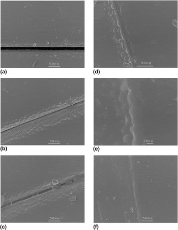
SEM micrographs (Fig. 9) show the Mn0.8 12 wt% film healing over different time periods in the AMF after a razorblade cut was made through the material. While the interface is in intimate contact within 60 s, total damage restoration takes longer. 20 min is sufficient to completely heal the film with not even a scar at the damage site.
SEM micrographs of cut healing in Mn0.8 12 wt% film at (a) 0 min, (b) 1 min, (c) 2 min, (d) 5 min, (e) 10 min, and (f) 20 min in the AMF.

The low time required for healing and the absence of scar formation is ideal in the case of insulating materials, as this will decrease the maintenance time while preserving the integrity of the wiring. Wear occurring during operation causes volume damage to the insulation. The ability of Magpol to heal wear damage was also studied.
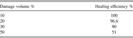
A pin on disc tribometer wear test was also used to simulate wear (chafing) that can occur in wire jacket materials. The 12 wt% composite films were subjected to various levels of damage by adjusting the circular path length, resulting in 10–50% wear through the material. Healing was then carried out in the AMF for 20 min. The degree of healing was determined by wearing through the healed path and measuring the total path length required to wear through the entire film. It was observed that up to 10% wear, the composite could recover completely, but beyond 10%, only partial recovery was observed due to the removal of large amounts of material from the damaged region, which could not be compensated for by movement of polymer chains from the surrounding areas into the damaged region. Table II shows the damage volume and healing efficiency corresponding to each volume.
Healing achieved over different damage volumes.
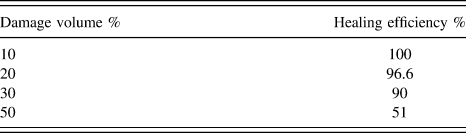
Initial wear of up to 10% can be completely healed by placing the damaged region in AMF for 20 min. Larger amounts of damage did not show complete healing. This may be due to the nature of the polymer EVA and depend on its melt flow rate. Higher melt flow rates will result in closure of the damaged region, but may also result in sample deformation. Further characterization is required to determine the effect of melt flow rate on the healing behavior of Magpol.
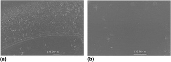
Figure 10 shows SEM images of the 30% worn sample of Mn08 12 wt% composite as well as the sample after exposure to an AMF for 20 min. The worn surface is completely restored to the original appearance and no visible scarring was apparent. This is significant as healing can return the surface to its original smoothness and decreases the severity of subsequent chafing.
SEM micrographs of (a) wear damaged 12 wt% Mn08 composite and (b) composite after undergoing healing cycle for 20 min in AMF.

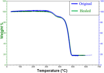
The Magpol composite does not undergo any degradation during exposure to the AMF. This was tested measuring the weight loss after exposing the highest loaded film, i.e., 16 wt% to the AMF for the maximum time used in the previous experiments, i.e., 20 min. Figure 11 shows the TGA curves for both the original and the exposed samples. The overlapping curves suggest that no thermal degradation has occurred during the healing process, with weight loss equal in both samples. Even though the maximum temperature of the sample rises to 220 °C as seen in Fig. 7, it remains below 300 °C at which degradation starts.
TGA weight loss curves of Magpol before and after exposure to AMF for 20 min.

Thus, the Curie temperature regulated heating is an efficient way to prevent pyrolysis of Magpol during self-healing. The Magpol composite was also found to be insulating even for the highest loading of 16 wt% (tests were conducted using four point probe resistivity measurement for conductivity at 32 V). These data are in agreement with current research, which shows that below the percolation values, nanomagnetic ferrite composites make good electrical and thermal insulating materials.Reference Tuncer, Rondinone, Woodward, Sauers, James and Ellis59,Reference Aphesteguy and Jacobo60
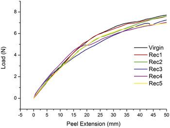
The 12 wt% Mn0.8 films were also subjected to cyclic damage and healing to check the repeatability of the healing process. The same samples were subjected to five cycles of damage and healing, and the results are shown in Fig. 12. The tear test was carried out up to 50 mm of peel extension in each case, to enable the torn edges to be held together for the healing cycle. Healing was carried out for 20 min in each cycle.
Load versus peel extension curves obtained by subjecting a 12 wt% Mn0.8 film to five cycles of damage and healing.

The maximum tear load is the same for the first two recovery cycles and then decreases slightly for the next three cycles. The tear direction remained the same in each case, which may be due to sample preparation or remnant damage, resulting in a decrease in the maximum tear load from the third recovery cycle onwards. This shows that Magpol can undergo repeated cycles of damage and repair without significant changes in its properties.
V. CONCLUSIONS
In this work, it has been shown that it is possible to incorporate healing functionality into materials for the development of self-healing wire insulation/jackets. This was achieved by using reptation based healing via heat generated by Curie temperature controlled nanoparticles embedded in a suitable thermoplastic matrix.
(1) MnxZn1−xFe2O4 magnetic nanoparticles were synthesized by the hydrothermal method. The Curie temperature could be tuned by changing the Mn to Zn ratio. The particles were coated with PEAA to prevent agglomeration and characterized by XRD, VSM, and TEM techniques. Characterization showed an increase in particle size, magnetization, and Curie temperature with increasing Mn content.
(2) These Mn–Zn ferrite nanoparticles were then used as fillers to synthesize 10, 12, and 16 wt% EVA composite films via the solution casting method. The films were subjected to an AMF to induce heat generation in the filler and consequently in the matrix. Increased loading resulted in higher temperatures, Mn0.8Zn0.2Fe2O4 containing films reached higher temperatures than Mn0.7Zn0.3Fe2O4 containing films.
(3) Heat generated in the films due to the magnetic component of the filler, repaired damage caused by the most common damage modes in wire insulation, i.e., chaffing and cut-through. The healing efficiency depends on the maximum achievable temperature and the time of exposure to the AMF. Superior recovery was observed in films containing Mn0.8Zn0.2Fe2O4, the extent of healing increased for longer exposure time.
(4) Thus, Curie temperature controlled heating of polymer films is an excellent option to develop self-healing polymeric materials as they ensure efficient healing of a variety of damage at greater penetration depths and without thermal degradation. By tuning the properties of the filler, it was possible to achieve greater healing efficiency at lower filler loading content and shorter healing time.
Supplementary Material
To view supplementary material for this article, please visit http://dx.doi.org/jmr.2015.59X.