. CdO particles are frequently observed on surfaces of whiskers and the alloy, indicating the importance of the oxidation process during the whisker growth; (ii) there exist four types of orientation relationship between Cd and CdO. The interfaces between them are shown to accommodate large lattice misfit, which is well explained by near coincidence site lattice model; (iii) nanosized Cd particles are observed to aggregate around the whisker root, providing a convincing experimental evidence for the long-range atomic diffusion. Our study offers a unique opportunity to unveil the relationship between unstability of quasicrystal structure and whisker formation and may have some implications for oxidation process of metals.
I. INTRODUCTION
Cd-based alloy is one of the most significant groups in quasicrystal field. Inspired by the idea of replacing Zn by Cd in icosahedral quasicrystal (IQC) Zn–Mg–RE (RE = Rare Earth element),Reference Luo, Zhang, Tang and Zhao1, Reference Niikura, Tsai, Inoue and Masumoto2 the stable quasicrystal of Cd–Mg–RE alloys were fabricated by Guo et al.Reference Guo, Abe and Tsai3 Concerning that Cd and Mg can be replaced by each other,Reference Guo, Abe and Tsai4 binary quasicrystal Cd5.7Yb eventually appeared.Reference Tsai, Guo, Abe, Takakura and Sato5, Reference Guo, Abe and Tsai6 This thermodynamically stable binary quasicrystal was truly a landmark for that it offered a unique opportunity to provide a basis for the construction of crystallographic models.Reference Takakura, Gómez, Yamamoto, De Boissieu and Tsai7 Unfortunately, the Cd-based alloys are very reactive and unstable, illustrated by the spontaneous whiskers growth on their surfaces in the air,Reference Wu, Ugurlu, Chumbley, Kramer and Lograsso8, Reference Krauss, Steurer, Ross and Lograsso9 leading to the degradation of the quasicrystal structure. Hence, a fundamental understanding of the detailed structure and nucleation mechanism of whisker is highly demanded.
Since the first discovery of Cd whiskers in 1946,Reference Cobb10 accumulated efforts have been dedicated into studying the spontaneous growth of low melting point metal whiskers including Sn, Cd, and Zn, etc., under ambient conditions. Despite the practical problems it may cause to the corresponding applications in electronic industry, whiskers were reported to possess remarkable mechanical properties such as high yielding strength.Reference Herring and Galt11 The whisker growth mechanism has consistently retained the attention of numerous researchers. In 1994, TuReference Tu12 put forward a theory that whiskers could grow at some localized stress relief centers where the surface oxide layer was broken. Later, Wu et al.Reference Wu, Lograsso and Anderegg13 suggested that oxygen was essential for the enhanced whisker growth kinetics observed after comparing the morphology, density, and growth rate of Cd islands and whiskers formed on surfaces of several Cd-based compounds. Now, it is widely accepted that whiskergrowth is a stress relief phenomenon.Reference Tu14–Reference Lee and Lee16 The strain gradient as a result of the mechanical (e.g., externally applied mechanical stressesReference Fisher, Darken and Carroll17–Reference Li, Bei, Zhai, Zhang, Zhou and Li19), thermal (e.g., diversity of thermal expansion during annealing pocessReference Shim, Ham, Lee, Jeung, Johnson and Lee20), and chemical stress is the driving force of the initial whisker recrystallization and growth.Reference Li, Bei, Zhai, Zhang, Zhou and Li19, Reference Lindborg21–Reference Sobiech, Wohlschlögel, Welzel, Mittemeijer, Hügel, Seekamp, Liu and Ice23 Generally, the spontaneous growth of whiskers requires an enduring driving force, which can be provided by chemical stress only. To be specific, the chemical reaction between oxygen and the sprouting metal could lead to volume expansion and induces the subsequent compressive stress, which could assist the atom diffusion and facilitate the extrusion process of the whisker.Reference Barsoum, Hoffman, Doherty, Gupta and Zavaliangos24–Reference Dudek and Chawla27 However, several important issues such as the kinetics of out-of-surface growth still remain to be addressed.
Besides, the metal oxidation itself is an intriguing issue for that the microstructures of the oxides have critical influence on the passivation behavior of metals.Reference Janousek and Carscallen28, Reference Chen, Shi, Chen, Granderson, George, Collins, Burger and James29 Simultaneously, numerous researches focused on basic mechanisms associated with different stages of oxidation process,Reference Yang, Yeadon, Kolasa and Gibson30 shape transition of oxides with distinct morphology,Reference Zhou, Wang, Birtcher, Baldo, Pearson, Yang and Eastman31 and various interfaces in the oxide scale,Reference Zhou32 etc. Thereby, the detailed crystallographic study of the metal whisker and its oxide phase may shed light on the kinetics of oxidation process.
In this paper, we report that in Cd–Mg–Yb ternary alloy, Cd whiskers can nucleate and grow spontaneously in the air, whose morphology and structure are investigated by electron microscopy in detail. CdO particles can be found on the whisker surface thanks to the oxidation process. Our experiment reveals four major types of structural relationship between Cd and CdO. The probable oxidation-induced whisker nucleation and growth mechanism is then discussed.
II. EXPERIMENTAL
The alloy was prepared from pure elements of Cd (99.99 wt%), Mg (99.99 wt%), and Yb (99.99 wt%), which were sealed in quartz tubes and then placed in Al2O3 crucibles, by induction furnace in an Ar atmosphere, followed by annealing at 673 K for 110 h under an Ar atmosphere. The nominal composition of the solid is Cd65Mg20Yb15.Reference Guo, Abe and Tsai3 Scanning Electron Microscopy (SEM) images were obtained by FEI Sirion FEG-SEM. For transmission electron microscopy (TEM) observations, the specimen was prepared by the conventional method, i.e., via the progressive steps of mechanical grinding, dimpling, and ion milling. Bright field (BF) and Dark field (DF) images and selected area electron diffraction (SAED) patterns were taken inside the JEOL JEM 2010HT electron microscope. Meanwhile, the energy-filtered transmission electron microscopy (EFTEM) images, high-resolution transmission electron microscopy (HRTEM) images, high-angle annular dark field scanning transmission electron microscopy (HAADF-STEM) images, and energy-dispersive x-ray spectrum (EDS) were acquired using JEOL JEM 2010FEF electron microscope equipped with Schottky field emission gun and Ω-type in-column energy filter system. The operating voltages of transmission electron microscopes are 200 kV.
III. RESULTS AND DISCUSSIONS
A. Major phase of Cd–Mg–Yb alloy
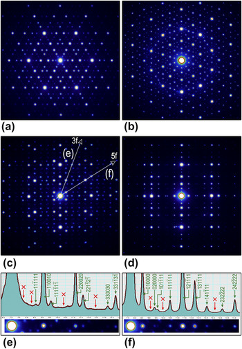
The dominant phase of the alloy is quasicrystal Cd65Mg20Yb15Reference Guo, Abe and Tsai3 as confirmed by SAED analysis shown in Fig. 1. The patterns were taken with incidences along 3-fold [Fig. 1(a)], 5-fold [Fig. 1(b)], and 2-fold directions [Fig. 1(c) and 1(d)], indicating the typical icosahedral symmetry of the phase. Intensity profiles along the 3-fold (“3f”) and 5-fold (“5f”) directions in the 2-fold pattern [Fig. 1(c)] are presented in Fig. 1(e) and 1(f), respectively. The spots are indexed based upon a cubic coordinate system of Cahn.Reference Cahn, Shechtman and Gratias33 The absence of spots associated with face-centered lattice (indicated by red arrows) suggests the presence of IQC with a primitive lattice. Quasicrystal lattice parameter determined from 44 strongest reflections of {221100} is 0.57 nm, identical with the value estimated from x-ray data.Reference Guo, Abe and Tsai3
SAED patterns of Cd65Mg20Yb15 along (a) 3-fold, (b) 5-fold, (c) 2-fold, and (d) pseudo-2-fold axes indicating quasicrystal nature of the phase. (e) and (f) Intensity profiles along 3-fold (“3f”) and 5-fold (“5f”) directions shown in (c), respectively; arrows point out the absent spots based on face-centered lattice.

B. Morphology and microstructure of whisker
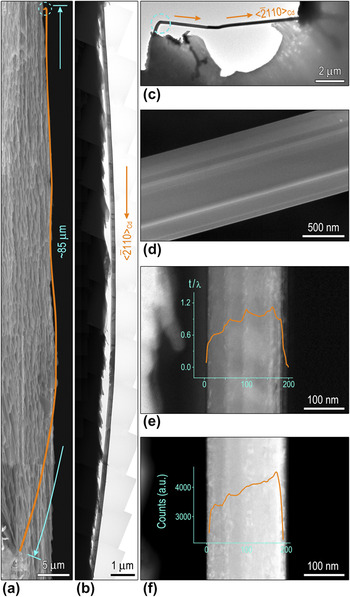
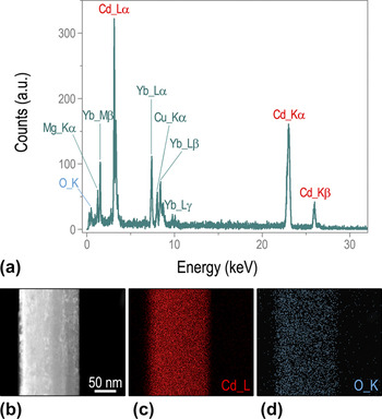
Interestingly, the whiskers appeared spontaneously after the specimen was held in a glass dryer for about 2 months at room temperature. Figure 2(a) is a SEM image showing a typical whisker with the length up to 85 μm, pseudocolored by the orange solid line. The corresponding TEM image is displayed in Fig. 2(b). In addition, another example is shown in Fig. 2(c). Generally, whiskers are straight with almost uniform diameters, although some of them may be bent at the base or have kinks at the tip. Besides, the striation contrast parallel to the whisker axis is clearly observed in a typical high-resolution SEM image [Fig. 2(d)]. The intensity profiles superimposed on the thickness map [Fig. 2(e)], applied by EFTEM image,Reference Egerton34 and the HAADF-STEM image [Fig. 2(f)] imply that the whisker possesses a “ridged” surface, i.e., irregular-shaped cross-section. Furthermore, the corresponding EDS signal [Fig. 3(a)] of a segment of the whisker shown in Fig. 2(a) reveals the existence of cadmium and oxygen. HAADF-STEM image [Fig. 3(b)] and the EDS elemental mapping of Cd [Fig. 3(c)] and O [Fig. 3(d)] show that both elements are evenly distributed.
(a) A SEM image showing a whisker with total length of 85 μm. BF images of the same whisker (b) and another whisker (c). (d) Typical high-resolution SEM image showing the striation contrast. (e) Thickness map obtained from EFTEM image and (f) HAADF-STEM image with intensity profiles superimposed imply the irregular-shaped cross-section of the whisker.

(a) EDS obtained from the whisker. (b) HAADF-STEM image and corresponding EDS elemental mapping of (c) Cd L and (d) O K.

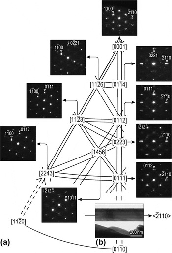
To investigate the detailed crystal structure of whiskers, a series of SAED patterns were taken [Fig. 4(a)]. The strong diffraction spots in the patterns can be indexed as pure Cd (JCPDS 85-1328, P63/mmc, Hexagonal, a = 0.2979 nm, c = 0.5618 nm). The growth direction is estimated to be along  [Fig. 4(b)], consistent with the previous report, whereas whiskers were grown in vacuum or in an inert gas atmosphere.Reference Lal, Peneva and Verma35–Reference Verma and Peneva37
(a) Systematic SAED patterns and (b) the BF image of a whisker showing the growth direction of  .

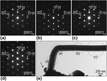
Subsequently, we focused on a bend portion of the whisker marked by dashed circle in Fig. 2(e). A higher magnified BF image of the bending is shown in Fig. 5(e) with corresponding SAED patterns [Fig. 5(a)–5(d)] taken at different areas [indicated by the dashed circles in Fig. 5(e)] without tilting the specimen. Surprisingly, all the patterns show little deviation with each other, whereas the strong spots can be indexed as the [0001] zone axis of Cd, implying the similar crystallographic orientation for different areas albeit the altered morphology. It is worth noting that a tiny freshly extruded whisker at the base also had an inclination to bend [pointed out by the arrow in Fig. 5(e)]. The above observation indicates that whiskers were initially forced to extrude with random directions and then would grow along the preferential direction (i.e.,  ).
(a)–(d) SAED patterns from different areas of a bending whisker. (e) BF image of the whisker showing its bending part.

C. Imperfection in whisker
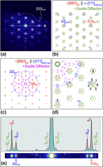
Further inspections of the pattern in Fig. 4(a) revealed that each diffraction spot of  was surrounded by six extra weak spots and a blurry hexagonal ring [Fig. 6(a)]. Besides those double diffraction spots, the extra spots could be indexed as [111] zone axis according to the CdO phase (JCPDS 78-0653,
 , Cubic, a = 0.4725 nm) (hereafter,
 ). The CdO diffraction spots are also observed in Fig. 5(b)–5(e). In view of no central symmetry of
 , four major types of orientation relationship (OR) between Cd and CdO can thus be deduced:
 ,
 (type Ia) and
 ,
 (type Ib), which have been reported as precipitate matrix OR in some metallic materials, e.g., Ag-rich γ precipitate (Hexagonal) plates in α Al–Ag matrix (Face-Centered Cubic)Reference Moore, Johnson, Howe, Aaronson and Veblen38;
 ,
 (type IIa) and
 ,
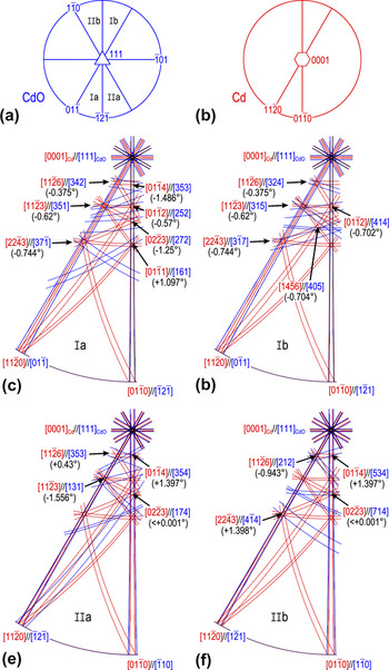
 (type IIb), which are similar to the Crawley OR between Hexagonal and Body-Centered Cubic materials.Reference Crawley and Milliken39, Reference Zhou, Zhao, Wang, Sun, Wang, Gui and Zheng40 All the four ORs are schematically illustrated by stereographic projections [Fig. 7(a) and 7(b)] and the stereographic Kikuchi patterns [Fig. 7(c)–7(f)]. Other CdO particles show random OR with Cd, leading to the occurrence of polycrystalline diffraction ring
 [Fig. 6(a)].
(a) Experimental SAED pattern along  . Simulated SAED patterns schematically illustrating (b) type Ia and Ib OR; (c) type IIa and IIb OR. (d) An enlarged fraction of Fig. 5(b) and 5(c). Red open circles present Cd spots, blue open squares denote CdO spots, green cross and pink cross mark type I and type II double diffraction, respectively. (e) Intensity profile along the line in (a) illustrating the misfit calculation.

Schematic stereographic projections along (a)  and (b)
 . (c)–(f) Stereographic Kikuchi patterns showing four types of OR between Cd and CdO.

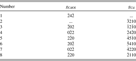
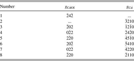
Concerning the kinematic effects, simulated composite SAED patterns are presented in Fig. 6(b) and 6(c) that are coincident with the experimental counterparts. Each figure exhibits two types of OR [Fig. 6(b) shows type Ia and Ib (type I hereafter) ORs, Fig. 6(c) shows type IIa and IIb (type II) ORs] and corresponding double diffractions (denoted as type I and type II double diffractions) originated from both Cd and CdO spots. As marked in Fig. 6(d) [an enlarged fraction of Fig. 6(b) and 6(c)], eight diffraction spots (denoted by Arabic numerals) could be indexed based on the reflections of Cd and CdO (Table I).Reference Jiang, Meletis, Yuan and Chen41, Reference Williams and Carter42 To be specific, diffraction spots 1 and 2 correspond to CdO and Cd phases, respectively, while spots 3–8 refer to type I double diffractions. This configuration can be used to precisely determine the natural lattice misfit between Cd and CdO, given by,


Indexed reflections associated with the marked diffraction spots in Fig. 6(d).
where  is the double diffraction vector as illustrated by intensity profile [Fig. 6(e)] along white solid line in Fig. 6(a). Hence,
 and
 are estimated to be (11.64 ± 0.06)% and (35.07 ± 0.20)% for type I and type II ORs, respectively. Both values are consistent with the theoretical natural lattice misfits using Eq. (1) (12.15% and 35.25%, respectively), indicative of the incoherent oxide–metal interface.
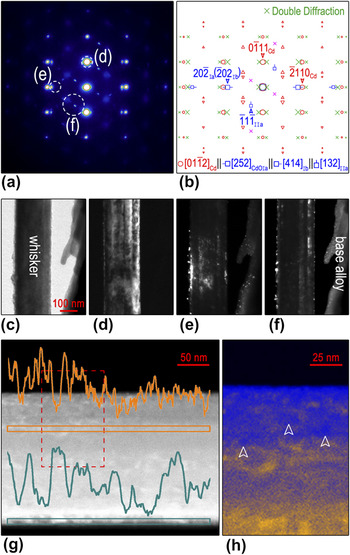
Figure 8(a) and 8(b) presents a typical SAED pattern taken along  and the related simulated pattern, respectively. BF [Fig. 8(c)] and DF images [Fig. 8(d)–8(f)] clearly show that pure Cd could be solely found on the whisker alone, while CdO particles existed not only on the whisker surface but also on the base alloy. The presence of CdO was also observed in other Cd alloy system,Reference Wu, Ugurlu, Chumbley, Kramer and Lograsso8 where the d-spacing labeled “1.65” should be {220}CdO. The size of CdO particles estimated from DF images is about several to tens of nanometers, as validated by width of the wave troughs of line profiles superimposed on a HAADF-STEM image [Fig. 8(g)], in which intensity is proportional to the thickness and the atomic number, and the size of relative dark region marked by arrows in Fig. 8(h). Accordingly, the whisker shown here was not pure crystal as generally considered. Instead, its surface was spotted with numerous tiny CdO particles. The frequently observed CdO particles indicated that the oxidation of Cd might contribute to the whisker growth process, which may be ignored in early report. For instance, the doublets of Laue spots with angular deformation reported in Refs. Reference Lal, Peneva and Verma35 and Reference Verma and Peneva37 might originate from the occurrence of CdO phase or double diffraction. It is speculated that these CdO particles sustain the driving force for follow-up growth of whiskers that already out-of-surface along the preferential direction and restrain horizontal growth simultaneously.
(a) Experimental SAED pattern along  . (b) The corresponding composite pattern simulated with kinematic theory. Red open circles and red open triangles present the zero-order and first-order Laue zone spots of Cd, blue open squares denote CdO spots, green cross and pink cross mark type I and type II double diffraction, respectively. (c) BF image and (d)–(f) corresponding DF images showing distribution and sizes of tiny CdO particles. (g) HAADF-STEM image with intensity profiles superimposed and (h) the enlarged view confirming the size estimation.

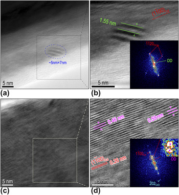
Figure 9(a) is a HRTEM image of a Cd whisker with a CdO particle residing on its surface. An enlarged Fourier-filtered image of the black-boxed area is shown in Fig. 9(b) with the fast Fourier-transformed (FFT) pattern as an inset. The size and orientation of the CdO particle can be estimated from the Moiré fringes (with an area of 5 × 7 nm) resulting from the overlapping of Cd and CdO crystal phases. This type I Double diffraction stemming from  and
 reflections contributed to Moiré fringe with approximate periodic spacing d m of 1.55 nm [Fig. 9(b)], comparable to the theoretical value of 1.37 nm applying the formula
 .Reference Williams and Carter43Figure 9(c) is another HRTEM image showing Moiré fringes that result from type II double diffraction. Moiré fringes with spacing 0.46 nm result from
 and
 and those with 0.59 nm come from
 and
 [Fig. 9(d)]. The presence of Moiré fringe was indicative of the incoherent interface at which the lattice was all relaxed.Reference Zhou44, Reference Zhou, Xu, Smith and Moustakas45
(b) and (d) Fourier-filtered images showing different Moiré fringes from the enclosed squares in (a) and (c), respectively. The insets in (b) and (d) are FFT patterns.

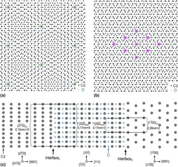
This incoherent-type interface was commonly observed in large mismatched metal oxide systems, well predicted by a near coincidence site lattice (CSL) model.Reference Li and Zuo46–Reference Nowak and Carter48 Specifically, given that M spacings in Cd match (M ± 1) spacings in CdO at the interface, the unit cell dimension of the interface superlattice thus equals to  . The natural lattice mismatch
 can be given via
 . In general, the system is not expected to be at exact coincidence, and a CSL misfit F expresses this deviation asReference Zhou32, Reference Trampert and Ploog49

Regarding type I OR  , the value of M is approximately 10 provided that the
 value is 11.64%. Thus for the interface I, a 10 × 9 CSL can be proposed with a minimum coincidence misfit of F I = 0.94%. For type II OR
 , a 2 × 3 CSL can be established with the coincidence misfit of F II = 2.87%. Note that the CdO is thought to be rigid and the strain is mainly accommodated by Cd whisker. The probable CSL configurations constructed according to two types of interface are presented in Fig. 10(a) and 10(b), respectively. Side view of the interface schematically shown in Fig. 10(c) illustrates the lattice match configuration more intuitively.
CSL models for (a) OR Ia and Ib, (b) OR IIa and IIb, respectively. (c) Side view of atomic models showing the atom configuration at two kinds of interface. For interface I (interface between Cd and CdO with type I OR), 10 spacings of  nearly match 9 spacings of
 , while at interface II (interface between Cd and CdO with type II OR), 2 spacings of
 nearly match 3 spacings of
 . The value of 0.17, 0.15, and 0.26 nm are the lattice spacings of
 ,
 , and
 , respectively.
 was chosen as the interface due to the small misfit between them (2.88%).

D. Structural evolution of quasicrystal
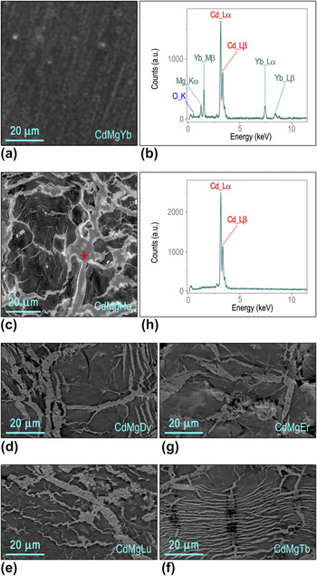
SEM image [Fig. 11(a)] of Cd–Mg–Yb alloy shows nearly homogeneous contrast, and the corresponding EDS pattern shows that it is consisted of Cd, Mg, Yb with a small amount of O [Fig. 11(b)]. Conversely, SEM images of other members among Cd–Mg–RE alloys, including Cd–Mg–Ho, Cd–Mg–Dy, Cd–Mg–Lu, Cd–Mg–Tb, and Cd–Mg–Er [Fig. 11(c)–11(g)], exhibit macrosegregation with heterogeneous contrast. The light region (marked by red asterisk) is pure Cd as validated by EDS in Fig. 11(h). Obviously, the absence of pure Cd in the as-fabricated Cd–Mg–Yb alloy demonstrates that the whisker grows with the depletion of Cd from the quasicrystal exclusively.
(a) A SEM image of Cd–Mg–Yb. (b) Corresponding EDS. SEM images of (c) Cd–Mg–Ho, (d) Cd–Mg–Dy, (e) Cd–Mg–Lu, (f) Cd–Mg–Tb, and (g) Cd–Mg–Er for comparison. (h) EDS obtained from light contrast area marked by red asterisk in (c).

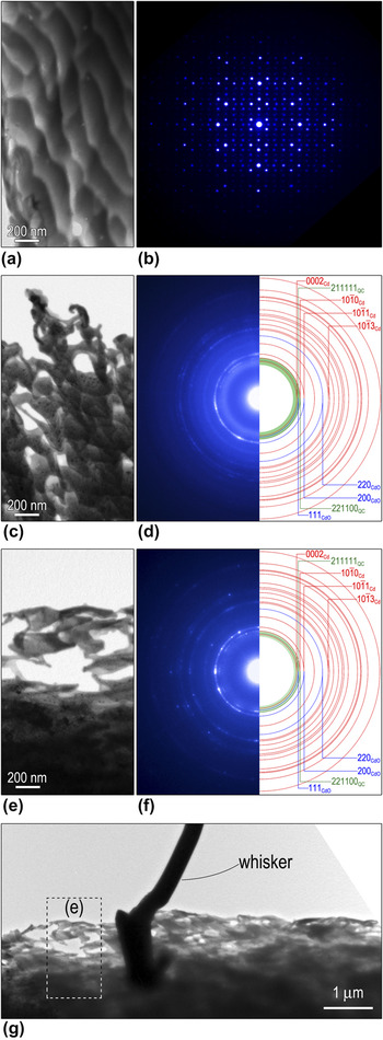
To illustrate the effect of the whisker growth on the alloy structure, sequential images showing the evolution of alloy morphology and the related SAED patterns are present in Fig. 12. The as-synthesized Cd–Mg–Yb alloy was single crystal [Fig. 12(b)] despite of its nonuniform morphology [Fig. 12(a)]. Strikingly, the alloy became incompact and porous [Fig. 12(c)] after whisker formation. Furthermore, corresponding SAED pattern [Fig. 12(d)] became ring-like pattern including contributions from Cd, CdO, and quasicrystal. Accompanied with the growth of whiskers, the quasicrystal structure degraded progressively [Fig. 12(e)] as indicated by the broadened and gradually invisible {221100} and {211111} reflections [Fig. 12(f)], characteristic of IQC. There is no evidence of other oxides, for instance, YbO (JCPDS 33-1452), Yb2O3 (JCPDS 84-1879), MgO (JCPDS 78-0430), MgO2 (JCPDS 76-1363), through meticulous examination, despite that Yb and Mg are easier to be oxidized than Cd according to the reactivity series and the standard electrode potentials. This anomalous selective oxidation may be owing to the different electronic and chemical state in the alloy from pure metal elements, which demands further investigations.
BF images showing the morphology evolution of the matrix (a) before and (c), (e) after the whisker growth. (b), (d), and (f) SAED patterns of the areas presented in (a), (c), and (e), respectively. (g) BF image showing typical morphology at the vicinity of a whisker root.

Actually, the typical holes riddled morphology [Fig. 12(c) and 12(e)] can only be found at the vicinity of a whisker root [Fig. 12(g)]. It is interesting to notice that there exist numerous nanosized Cd particles around the root indicated by the sharp and discontinuous ring-like diffraction pattern [Fig. 12(f)]. Our gentle reminder is that no Cd particles could be found at the region far away from the whisker root [Fig. 8(d)]. It implies that Cd particles were transported, as driven by the stress gradient,Reference Choi, Lee, Tu, Tamura, Celestre, MacDowell, Bong and Nguyen22, Reference Sobiech, Wohlschlögel, Welzel, Mittemeijer, Hügel, Seekamp, Liu and Ice23 to the root to supply the continuous whisker growth. This observation is a remarkable experimental evidence for the long-range atomic diffusion.
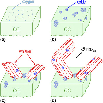
Based on our experiment, a schematic oxidation-induced model on whisker growth is shown in Fig. 13. During the first step, oxygen adsorb onto the quasicrystal surface [Fig. 13(a)]. Second, randomly distributed CdO particles nucleate [Fig. 13(b)], resulting in the displacement of Cd atoms within the alloy and volume expansion, which induces heterogeneous compressive stress. Third, when the amount of Cd atoms and the stress accumulate to a certain level, recrystallization begins and whiskers are extruded out of the surface. Abundant Cd atoms are transported unceasingly to the whisker root to supply its growth. Some CdO particles might be carried out with whisker formation [Fig. 13(c)]. Since whisker is constrained while breaking through the surface, the initial extruded direction is not identical. Finally, once the whisker breaks out of the surface and is away from the stress field, it would grow along the preferential direction (i.e.,  ) [Fig. 13(d)]. CdO particles on its surface might sustain the driving force for follow-up growth and restrain horizontal growth simultaneously. Whisker growth leads to gradual decreasing of Cd component in quasicrystal and eventually reorganizes crystal structure.
Schematic diagram of the growth process of the whiskers. (a) Oxygen adsorption on the surface. (b) Oxide islands formation. (c) Sprouted whiskers from the alloy. (d) Subsequent free growth of the whiskers.

III. CONCLUSIONS
To sum up, the spontaneous growth of whiskers is observed in Cd–Mg–Yb alloy, which originally possesses almost uniform phase, i.e., IQC. No matter what directions the whiskers are extruded; they would turn to the preferential growth direction  eventually, resulting in the characteristic bending at the whisker base. The whisker is mainly composed of Cd and its surface is spotted with numerous tiny CdO particles. Lattice misfits determined from double diffractions between Cd and CdO are comparable to the calculated ones indicating that the lattices are relaxed. The oxidation-induced whisker nucleation and growth mechanism is thus discussed. Interestingly, we observed the aggregation of nanosized Cd particles at the vicinity of the whisker root, indicative of the long-range atom diffusion. The gradual decreasing of Cd component in the alloy leads to the degradation of the quasicrystal quality.
ACKNOWLEDGMENTS
The research was supported by the National Natural Science Foundation of China (51071110, 50571075), the Program for New Century Excellent Talents in University (NCET-07-0640), and Chinese Universities Scientific Fund. Guo JQ is thanked for sample providing.