1. Introduction
Stroke is defined as the loss of one or more neurological functions due to the interruption of blood flow in a certain region of the brain [Reference Virani, Alonso, Aparicio, Benjamin, Bittencourt, Callaway, Carson, Chamberlain, Cheng, Delling, Elkind, Evenson, Ferguson, Gupta, Khan, Kissela, Knutson, Lee, Lewis, Liu, Loop, Lutsey, Ma, Mackey, Martin, Matchar, Mussolino, Navaneethan, Perak, Roth, Samad, Satou, Schroeder, Shah, Shay, Stokes, VanWagner, Wang and Tsao1]–[Reference Alves, Gonçalves and Carbone8]. The rehabilitation process for stroke is currently applied through protocols developed by health professionals and potentially augmented by the use of robotic tools [Reference Barbosa, Carvalho and Gonçalves9, Reference Hobbs and Artemiadis10].
There is evidence of the advantages promoted by the application of robotic structures in rehabilitation, such as reducing costs with active labor for training sessions and expanding the range of exercises performed [Reference Hobbs and Artemiadis10].
The body weight-supported treadmill training emerged as one option of gait rehabilitation, where the patients were suspended by a body weight support (BWS) harness over a treadmill, while two or three therapists assisted the gait procedure, two sitting adjacent to the paretic leg to reproduce the gait movement and other therapist standing behind the patient to shift the body weight. To automatize this procedure, researchers starts to develop robotic tools to replace/help the physiotherapists [Reference Hobbs and Artemiadis10].
In ref. [Reference Kooij12] was developed the rehabilitation robot called LOPES that is an exoskeleton attached to patients’ lower limbs over a treadmill. The structure has active BWS that releases the passive weight from the lower limbs and acts only in the translation of the pelvic joint, and the pelvis rotations are constrained. In ref. [13] was explored the development of a body weight supporting while active assisting pelvic movements: vertical, lateral, and frontal translations as well as the rotation about the vertical axis.
Another example of treadmill-based structures is called robotic gait rehabilitation (RGR) [Reference Pietrusinski, Cajigas, Mizikacioglu, Goldsmith, Bonato and Mavroidis14]. It consists of a rehabilitation treadmill system designed specifically to assist in the treatment of gait in poststroke patients. The RGR robot is connected to the pelvic joint of the patient using an orthosis with two free movements in the horizontal plane and one active in the vertical direction.
The pelvic assist manipulator (PAM) is a rehabilitation structure focused on assisting treadmill exercises by actuating on the pelvic joint [Reference Aoyagi, Ichinose, Reinkensmeyer and Bobrow15]. The movements are generated by pneumatic cylinders organized on a tripod structure that permits three active pelvis translations and two rotations with the pelvic tilt not controlled.
One commercial rehabilitation device that applies BWS and a treadmill is the Lokomat (Jezernik et al., 2004). This robotic orthosis features two serial structures that actuate directly on the lower limbs during rehabilitation training sessions. Lokomat has an optional module that permits the lateral translation and transverse rotation of the pelvis [Reference Aurich-Schuler, Gut and Labruyère16].
The body weight support system (BWSS) can aid in gait rehabilitation providing weight relief that reduces the muscle’s demand and can make it easier to coordinate limb motion. The use of BWSS permits patients with limited strength training the walking [Reference MacLean and Ferris17]. Studies realized indicated that BWSS to gait practice can improve walking ability in people with stroke, Parkinson’s, or incomplete spinal cord injury [Reference MacLean and Ferris17].
Despite the advances in the application of BWSS in gait rehabilitation, the benefits have been inconclusive. It appears that robotic structures for rehabilitation on treadmills with passive weight support influence the balance and movements of the pelvis and thorax during gait [Reference Swinnen18, Reference Hesse19]. The design of the BWSS user alone or together with gait training robots, usually, is a static device that does not adapt to changes in trunk height. Some BWSS have passive or controllable vertical movements but limited pelvis movements.
In this paper, the development of a novel structure for the rehabilitation of human gait is carried out, aimed at the treatment of victims of stroke, cerebral palsy, and other pathologies that cause problems in the rhythmic gait, aiming to promote functional gains to patients, increasing the motor capacity of the patients injured lower limb. It is noteworthy that this paper brings innovation to the rehabilitation of human gait assisted by robotic structures by proposing a parallel structure of five degrees of freedom based on a family of mechanisms with low coupling between joint coordinates. Through the use of this unique design for the rehabilitation of human gait, the aim is to obtain a structure capable of withstanding the passive weight of patients and promoting controlled actions without the need for high-power actuators and without compromising the workspace with singularities.
This work proposes the use of an active BWS acting on the relevant degrees of freedom of the pelvis for the rehabilitation of human gait capable of performing the three translations, and rotations under the frontal and transverse planes, restricting only the sagittal plane.
This paper is structured as follows: Section 2 explains the importance of the pelvic joint, Section 3 provides the mathematical model of the proposed novel BWSS, followed by the implementation of the mechanical structure, Section 4, and the control system design, Section 5. The serious game developed is presented in Section 6. The experimental tests and results are analyzed and discussed in Section 7. Finally, the conclusions and recommendations are drawn in Section 8.
2. Pelvic join movements
The sacroiliac joint, also known as the pelvic joint, is the connection between the base of the cervical spine (sacral bone) and the articular surfaces of the ilium of the pelvis. It is a joint of low mobility and high stability and plays a key role in balance. In this way, the physiological function of this joint is more connected to stability than to excess mobility. Although the range of your movements is limited, these are important to ensure the stability of the body when associated with hip and low back movements. This mobility can even functionally help patients with gait irregularities [Reference Liang20]. The sacroiliac joint has three degrees of freedom of rotation with the following amplitudes: 25° of rotation in the transverse plane, 5° of rotation in the sagittal plane, and 2° of rotation in the frontal plane [Reference I.21].
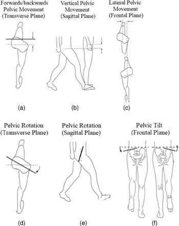
This paper describes the novel BWSS device for gait rehabilitation through pelvis facilitation movements. Five degrees of freedom are actuated: vertical, transverse, and frontal translation as well as the rotation about the frontal and transverse planes, Fig. 1.
Pelvic facilitation is a method used by physiotherapists together with treadmill-based therapies that include pelvis movements. Some robotic trainers focus on the leg and feet, and evidence from the literature indicates that a pelvis-based robot could have a large impact on the gait [Reference Lewis, Laudicina, Khuu and Loverro22]. The movement of the pelvis can impart swing energy to the leg even when hip and knee muscles are weak, and a pilot study found that patients who were being rehabilitated through pelvis actuation showed more brain activity compared to the patients rehabilitated by moving the legs through gait [Reference Ohnuma and Lee23].
The pelvis motions involve the translation vertical, lateral and frontal movements, and transverse, coronal and sagittal rotations, as shown in Fig. 1.
Pelvis movements associated with the gait.

The pelvis transverse translation, as shown in Fig. 1(a), is relative to average forward/backward displacement. The transverse displacement could improve gait symmetry and gait speed.
The pelvic vertical translation degree of freedom, as shown in Fig. 1(b), is related directly to the BWS forces. The literature showed that stroke treadmill training using BWS is more effective than with no BWS [Reference Ohnuma and Lee24]. The BWS supports part of the patient’s weight and reduces the amount of muscle function required to walk facilitating the rehabilitation process early. The possibility of vertical BWS can help the patient transfer energy between the gravitational potential to kinetic forms making the gait process more energy efficient.
The lateral pelvic movement, as shown in Fig. 1(c), is necessary to weight shift towards the stance leg that allows the swing leg to be lifted. The stroke can cause asymmetric deficiencies, and the patients can have difficulty balancing on their paretic limb which is used in conventional physiotherapy [Reference Ohnuma and Lee23]. The pelvis transverse rotation, as shown in Fig. 1(d), permits the hips to move frontally relative to each other. Combining transverse displacement and transverse rotation could prevent knee hyperextension in stroke patients [Reference Ohnuma and Lee23].
The pelvis sagittal rotation, as shown in Fig. 1(e), on the axis of rotation, that connects the hips is not used in the gait process directly [13, Reference Ohnuma and Lee23] and is not considered an active degree to be controlled in this paper.
The pelvis frontal rotation, as shown in Fig. 1(f), occurs when one hip rises relative to the other. Stroke patients can produce abnormal frontal rotations while walking to increase ground clearance for the paretic leg swing side. The physiotherapists compensate for this problem by pushing down on the affected side of the hip during the swing which involves uncomfortable postures for the health professional.
The importance of freedom for the movement of the pelvis is further evidenced when analyzing the so-called pelvic step, which consists of the rotation movement of the pelvis in the transverse plane, which increases the step length during human gait, reducing the vertical movements of the pelvis and center of mass of the body [Reference Ohnuma and Lee23]. Although it has been shown that transverse rotation of the pelvis may be out of phase with hip movement during gait at low speeds and small steps, this movement may help patients with low mobility for hip flexion movements to increase stride length, which can contribute to increasing their mobility [Reference Ohnuma and Lee23]. There is also evidence that restriction of pelvis movement can also significantly interfere with stride width and rotations in the frontal and sagittal planes of the body during gait and should be avoided for more efficient training [Reference Veneman24].
3. Mathematical modeling of the novel active BWS
The proposed novel active BWSS consists of a parallel robotic structure with five degrees of freedom, three degrees related to three-dimensional spatial translation, and two degrees of rotation. The main therapeutic objective of this support is to promote assisted training of the pelvic joint during the gait training session. In this way, the structure aims to promote more efficient training capable of facilitating improvements in patients’ balance.
3.1. Inverse geometric model
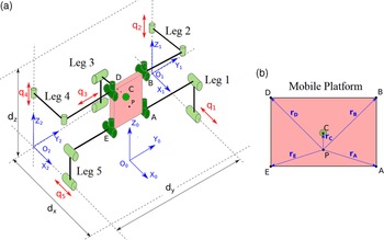
The design of the structure was carried out to minimize the coupling of the joint coordinates of the structure through the application of an architecture based on the “multipteron” family [Reference Gosselin, Laliberté and Veillette25, 26], keeping only the sagittal movement of the pelvis mechanically restricted due to its low influence on the rehabilitation process of human gait [13, Reference Ohnuma and Lee23]. For this, we propose the application of a structure defined as 4-PRRU + PRRS as a form of “pentapteron,” as shown in Fig. 2, where
 $P$
is an actuated prismatic joint,
 $R$
represents a rotational joint,
 $U$
is a universal joint, and
 $S$
represents a spherical joint. Point P of the mobile platform is the point where a seat for the patient will be installed.
(a) Schematic drawing for the structure of the active support of the pelvis, based on the “pentapteron” (4-PRRU + PRRS); and (b) position of the point of interest P in relation to the vertices of the mobile platform.

Analysis of the position of point A in relation to the inertial frame and leg 1.

In Fig. 2, translational and rotational joints have been grouped into cylindrical joints
 $q_{i},i=1to5$
, to facilitate representation in the scheme. However, translation and rotation joints were used during the construction of the prototype described in Section 4. The universal joints are represented by cross-cylinders, and the spherical joint as a dashed circumference placed behind the mobile platform, Fig. 2.
For the modeling of this system, equipollent coordinates [Reference Selig27] were used for the references illustrated in Fig. 2(a) so that each joint coordinate
 $q_{i}$
is in one of the directions of the unit vectors of the frame of reference. Therefore, for each leg
 $i$
, the vector
 $u_{i}$
that connects the active joint of this leg to one of the points on the mobile platform that belongs to a plane perpendicular to the unit vector of the actuator direction is highlighted. Based on these facts, we proceed with the modeling of this structure, analyzing each leg
 $i$
individually and systematizing the equations obtained in a matrix relating to the joint and operational coordinates.
To analyze the position of point A of the mobile platform from a leg
 $i$
in relation to the inertial reference can be equated with the position in relation to the references of the leg in question. For the case of leg 1, this relationship is illustrated in Fig. 3 and formalized in (1).
 \begin{equation} \,^{\mathbf{0}}\,\mathbf{\!r}_{\mathbf{p}}+\mathbf{r}_{\mathbf{A}}= {}^{\mathbf{0}}\mathbf{r}_{\mathbf{1}}+q_{1}\mathbf{i}_{\mathbf{1}}+\mathbf{u}_{\mathbf{1}} \end{equation}
where
 $^{\textbf{0}}{\textbf{r}}_{\textbf{p}}$
is the position of point P with respect to
 $X_{0}Y_{0}Z_{0}, \textbf{r}_{\textbf{A}}$
is the relative position of point A with respect to point
 $P$
, and
 $\textbf{i}_{\textbf{1}}$
is the unit vector of the X direction of reference frame
 $X_{1}Y_{1}Z_{1}$
. The vector u1 belongs to a plane parallel to the plane
 $Y_{1}Z_{1}$
, therefore perpendicular to the unit vector
 $\textbf{i}_{\textbf{1}}$
, and that
 $\textbf{i}_{\textbf{1}}$
=
 $\textbf{i}_{\textbf{0}}$
due to the fact of adopting references with equipollent coordinates. Therefore, when performing a dot product on both sides of (1) by
 $\textbf{i}_{\textbf{0}}$
:
 \begin{equation} q_{1}=\left({}^{\mathbf{0}}\mathbf{r}_{\mathbf{p}}+\mathbf{r}_{\mathbf{A}}- {}^{\mathbf{0}}\mathbf{r}_{\mathbf{1}}\right)\cdot \mathbf{i}_{\mathbf{0}}=\left(\left\{^{0}{r}_{p_{x}}^{0}{r}_{p_{y}}^{0}r_{{p_{z}}}\right\}+\left\{r_{{A_{x}}}r_{{A_{y}}}r_{Az}\right\}\!-\!\left\{-\frac{dx}{2}\frac{dy}{2}0\right\}\right)\!\cdot\! 100\Rightarrow q_{1}= {}^{0}r_{{p_{x}}}+\frac{dx}{2}+r_{A}\cos \phi \end{equation}
where
 $\phi$
corresponds to the angle between the vectors
 $\textbf{r}_{\textbf{A}}$
and
 $\textbf{i}_{\textbf{0}}$
, as illustrated in Fig. 4, which is also defined as the orientation of the mobile platform in terms of its rotation around the
 $Z_{0}$
axis.
Angles between the unit vectors and the position vectors of the ends in relation to point P: (a) angles of rotation around X 0; and (b) rotation around Z 0.

The analogous procedure is made to legs 2 to 5 to obtain the following equations:
 \begin{equation} q_{2}=\mathbf{(}^{\mathbf{0}}\mathbf{r}_{\mathbf{p}}+\mathbf{r}_{\mathbf{B}}- {}^{\mathbf{0}}\mathbf{r}_{\mathbf{1}}\mathbf{)}\cdot \mathbf{k}_{\mathbf{0}}\mathbf{q}_{\mathbf{2}}= {}^{0}\!r_{{p_{z}}}+r_{B}\cos \theta \end{equation}
where angle
 $\theta$
corresponds to the angle between the unit vector
 $\textbf{k}_{\textbf{0}}$
and the vector
 $\textbf{r}_{\textbf{B}}$
, as illustrated in Fig. 4.
 \begin{equation} q_{3}=\,^{0}r_{py}+r_{C}\cos\! \left(\theta +\psi \right)+\frac{dy}{2} \end{equation}
where angle
 $\phi +\psi$
represents the orientation around the
 $X_{0}$
axis of the mobile platform, as shown in Fig. 4.
 \begin{equation} q_{4}=\,^{0}r_{pz}+r_{D}\;cos(\theta +\phi ) \end{equation}
where angle
 $\theta +\varphi$
is the angular difference between vector
 $\textbf{r}_{\textbf{D}}$
and unit vector
 $\textbf{k}_{\textbf{0}}$
, as defined in Fig. 4.
 \begin{equation} q_{5}= {}^{0}r_{px}-r_{E}\cos\! \left(\varphi \right)+\frac{dx}{2} \end{equation}
Equations (2) to (6) present the relations of the operational coordinates
 $^{\textbf{0}}\textbf{r}_{\textbf{p}}, \theta$
, and
 $\varphi$
with the joint coordinates
 $q_{1}, q_{2}, q_{3}, q_{4}$
, and
 $q_{5}$
. Through these, it is possible to find the Jacobian matrix of the structure, which is used to determine the possible singular positions.
3.2. Singularity analysis
First, it is necessary calculate the time derivative of (2) to (6). Their respective time derivatives are presented in (7a) to (7e) and the matrix form,
 $[J_{q}]\{\dot{q}\}=[J_{x}]\{\dot{x}\}$
, that groups these equations is presented in (7f):
 \begin{equation} \dot{q}_{1}= \dot{\,^{0}r_{px}}-r_{A}\sin\!\left(\varphi \right)\!\dot{\varphi } \end{equation}
 \begin{equation} \dot{q}_{2}= \dot{\,^{0}r_{pz}}-r_{B}\sin\!\left(\theta \right)\!\dot{\theta } \end{equation}
 \begin{equation} \dot{q}_{3}= \dot{\,^{0}r_{py}}-r_{C}\sin\!\left(\theta +\psi \right)\!\dot{\psi } \end{equation}
 \begin{equation} \dot{q}_{4}= \dot{\,^{0}r_{pz}}-r_{D}\sin\! \left(\theta +\phi \right)\!\dot{\theta } \end{equation}
 \begin{equation} \dot{q}_{5}= \dot{\,^{0}r_{px}}+r_{E}\sin\! \left(\varphi \right)\!\dot{\varphi } \end{equation}
 \begin{equation} \left[J_{q}\right]\left\{\dot{q}\right\}=\left[J_{x}\right]\left\{\dot{x}\right\}\Rightarrow \left\{\begin{array}{c} \dot{q}_{1}\\[5pt] \dot{q}_{2}\\[5pt] \dot{q}_{3}\\[5pt] \begin{array}{c} \dot{q}_{4}\\[5pt] \dot{q}_{5}\\[5pt] \end{array}\,\\[5pt] \end{array}\right\}=\left[\begin{array}{c@{\quad}c@{\quad}c@{\quad}c@{\quad}c} 1 & 0 & 0 & 0 & -r_{A}\;\textrm{sin}\!\left(\varphi \right)\\[5pt] 0 & 0 & 1 & -r_{B}\sin\!\left(\theta \right) & 0\\[5pt] 0 & 1 & 0 & -r_{C}\sin\!\left(\theta +\psi \right) & 0\\[5pt] 0 & 0 & 1 & -r_{D}\sin\!\left(\theta +\phi \right) & 0\\[5pt] 1 & 0 & 0 & 0 & r_{E}\sin\!\left(\varphi \right) \end{array}\right] \left\{\begin{array}{c} {}^{0}{\dot{r}_{{P_{x}}}} \\[5pt] {}^{0}{\dot{r}_{{P_{y}}}} \\[5pt] {}^{0}\dot{r}_{{P_{z}}} \\[5pt] \dot{\theta } \\[5pt] \dot{\varphi } \end{array} \right\} \end{equation}
In this way, it is possible to notice that
 $[J_{q}]=[I]$
, which means that the singular positions will exist only for the case where
 $\det\! ([J_{x}])=0$
. Therefore, these cases can be expressed according to (8):
 \begin{equation*} \det\! \left(\left[J_{x}\right]\right)=r_{A}r_{D}\sin\!\left(\phi +\theta \right)\sin\!\left(\varphi \right)-r_{B}r_{E}\sin\!\left(\theta \right)\sin\!\left(\varphi \right)- \end{equation*}
 \begin{equation*} -r_{A}r_{B}\sin\! \left(\theta \right)\sin\! \left(\varphi \right)+r_{D}r_{E}\sin\! \left(\phi +\theta \right)\sin\! \left(\varphi \right)=0 \end{equation*}
 \begin{equation} \Rightarrow r_{D}\sin\! \left(\phi +\theta \right)=r_{B}\sin\! \left(\theta \right) \end{equation}
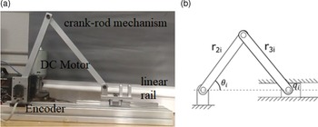
(a) Prototype of the motor module and (b) schematic drawing of the mechanism.

Therefore, whenever (8) is true, the system will be in a position of singularity and will be subject to loss of control and/or problem of mobility in this position. Based on this information, to design this structure it is necessary to guarantee that the selected dimensions of
 $r_{B}, r_{D}$
, and
 $\phi$
do not allow the occurrence of (8) at no point in the workspace at
 $\theta$
. It is also possible to notice that the translational degrees of freedom of this structure are limited only by the respective limits of the workspace, since these do not present terms in the Jacobian matrix
 $[J_{x}]$
.
To reduce the cost of high-speed linear actuators, an actuator model was proposed, based on 24-V DC motors coupled to rotary encoders, and the angular movement of these motors was transformed into linear displacement through a 3-bar crank-rod mechanism type. The scheme designed for this system is represented in Fig. 5, and the relationship between
 $q_{i}$
and
 $\theta _{i}$
is described in (9).
 \begin{equation} q_{i}=r_{2i}\cos \theta _{i}+\sqrt{{r_{3i}}^{2}-{r_{2i}}^{2}\;sin^{2}\theta _{i}} \end{equation}
3.3. Dynamic model and simulation optimization
To define the dimensions of the mechanical elements and actuators, a computational model considering geometric and dynamic characteristics was developed. The patient’s mass was considered as punctual dynamic loading generated by it on the linear guides
 $q_{i}$
and transmitted to the DC motors
 $M_{i}$
through the connecting crank-rod mechanism. The approach is valid due to the low speeds and accelerations present in the kinematics of human gait rehabilitation [Reference Gonçalves and Krebs28]. Therefore, the mass and inertia of the bars and other mechanical elements present in this module can be disregarded without prejudice to the system specifications. A critical mass
 $M_{P}=150\,{\rm Kg}$
was considered.
The movement requirements were established according to the human gait with a focus on the sacroiliac joint, as shown in Table V.
For the calculation of the dynamic model, it was considered: bars that connect the module’s mobile platform to the linear guides must withstand the maximum static load, specified as the critical mass of the system; linear guides must traverse the specified workspace within the critical cycle time (
 $t_{c}=0.4\,{\rm s}$
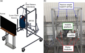
); bars that connect the linear guides to the DC motors must punctually support the maximum dynamic load, disregarding the effect of inertia to simplify the model; actuators 2 and 4 will be implemented together with a passive spring system to relieve the patient’s static load, as shown in Fig. 6, allowing actuators to focus only on dynamic efforts; and an additional spring has been connected to the mobile platform, as shown in Fig. 6, without prejudice the defined workspace, to improve the passive support of the structure and relieve the static load of the other actuators.
(a) CAD version and (b) the built prototype.

Therefore, from the proposed directives, it is defined that the linear guides must be able to start their respective trajectories from the beginning of the course with zero initial velocity and finish the movement in the final position again with zero velocity. The dynamic equation that defines the greatest effort
 $F_{i}$
applied under each actuator
 $q_{i}$
can be defined as:
 \begin{equation} \mathbf{F}_{\mathbf{i}}=\mathbf{f}_{\mathbf{r\,i}}\mathbf{M}_{\mathbf{P}}\frac{\mathbf{d}_{\mathbf{i}}}{{\mathbf{t}}_{\mathbf{c}}^{\mathbf{2}}}\quad \mathbf{i}\;\mathbf{=}\;\mathbf{1}\mathbf{,}\,\mathbf{2}\mathbf{,}\,\mathbf{4}\mathbf{,}\,\mathbf{5}\Rightarrow \mathbf{f}_{{\mathbf{r}_{\mathbf{i}}}}\;\mathbf{=}\;\mathbf{0}\mathbf{.}\mathbf{5}\,\,\mathbf{i}\;\mathbf{=}\;\mathbf{3}\Rightarrow \mathbf{f}_{\mathbf{r\,i}}\;\mathbf{=}\;\mathbf{1}\,\, \end{equation}
where
 $d_{i}$
corresponds to the working space specified for each linear guide rail,
 $t_{c}$
is the time to complete the gait cycle considered as
 $0.4\,{\rm s}$
, and the parameter
 $f_{ri}$
corresponds to a correction factor applied in the equation to consider the weight distribution between actuators 1 and 5, and actuators 2 and 4. The actuator 3 acts alone in the
 $j_{0}$
direction, which means that it does not need correction, and therefore
 $f_{r3}=1$
. The model also considers the minimum requirements for electrical power and angular speed of the specified DC motors to allow the correct movement of the connecting crank-rod mechanism. A free body diagram was constructed showing the considered efforts, as shown in Fig. 7. In this diagram,
 $T_{i}$
represents the input angular momentum of the motor
 $M_{i}$
, and
 $F_{i}$
is the force applied on
 $q_{i}$
.
Free body diagram of the connecting crank-rod mechanism of the actuators.

Applying the equilibrium moment conditions to the free body diagram in Fig. 7, with respect to the point
 $E_{i}$
, the moment
 $T_{i}$
can be written as:
 \begin{equation} T_{i}=F_{i}r_{2i}\;sin\,\theta _{i} \end{equation}
differentiating (9) in time and isolating
 $\dot{\theta }_{i}$
is obtained:
 \begin{equation} \dot{\theta }_{i}=\frac{\dot{q}_{i}}{-r_{2i}\;sin\,\theta _{i}-\frac{{r_{2i}}^{2}\;sin\,\theta _{i}\;cos\,\theta _{i}}{\sqrt{{r_{3i}}^{2}-{r_{2i}}^{2}\;sin^{2}\,\theta _{i}}}} \end{equation}
Therefore, to obtain the expression for the minimum power required for each electric motor is applied (13):
 \begin{equation} P_{i}\left[W\right]=\frac{\theta _{i}\tau _{i}}{9.55} \end{equation}
To calculus the tension applied to the cross sections of each bar, was used as a criterion for the comparison
 $\sigma _{ij}$
of the stress calculated in each cross section through the theory of strength of materials [Reference Uicker, Pennock, Shigley and McCarthy29], according to (14), where
 $F_{j}$
are the efforts applied to the element,
 $r_{ij}$
is the analyzed bar, and
 $I_{ij}$
is the moment of inertia of the bar:
 \begin{equation} \sigma _{ij}=\frac{F_{j}r_{ij}}{4I_{ij}} \end{equation}
To obtain the optimal dimensions of the bars that will compose the mechanism, the tension calculated according to (14) is compared with the yield strength of the selected material defined as aluminum (
 $\sigma _{max}=180\,{\rm MPa}$
). To facilitate the bar specification process and reduce manufacturing costs, all bars in the system were considered as rectangular tubes with cross sections compatible with the materials available. The factor of safety equal two was used. All the requirements were combined in a computational model developed in MATLAB® together with a differential evolution algorithm forming an interactive simulation optimization system. The simulation optimization parameters are number of replications = 10, population size = 50, maximum iterations = 200, crossover rate = 0.8, and mutation probability = 0.005.
The results obtained through this process are shown in Table I. The bars
 $r_{2i}$
and
 $r_{3i}$
are the ones that make up the connecting crank-rod mechanism of each actuator
 $i$
, being all similar to each other, as shown in Fig. 5. The bars
 $r_{4i}$
and
 $r_{5i}$
represent the connection bars between the linear guide rail and the mobile platform for each leg
 $i$
, as shown in Fig. 1.
The simulation also determined the necessary characteristics for the DC motors, as shown in Table II, as described in (12) and (13).
4. Implementation of BWS
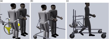
This section presents the design and implementation of the active BWSS for gait rehabilitation. The manufacture prototype is shown in Fig. 6(b). The novel proposed device is designed to impose minimum constraints on the user, with intrinsically minimizes the donning and doffing time, as shown in Fig. 8. The proposed device can be used for overground rehabilitation in patients that can walk alone, as shown in Fig. 8(c), or together with a treadmill, or other exoskeletons that can be coupled with the legs.
Optimal dimensions calculated for each module bar.

Specifications for the module’s DC motors.

The sequence of the image shows the patient donning process. (a) Removing the patient from the wheelchair; (b) donning the patient to the device; and (c) overground rehabilitation exercises.

The proposed device is used in the pilot study with a treadmill (Movement R4, 1250 × 440 mm, speed 1 to 14km/h), utilized to forward propulsion and simulate the gait together with the serious game developed. The use of the treadmill is justified in the function of the availability of this device in rehabilitation clinics [Reference R.Haghjoo, Lee, Afzal, Eizad and Yoon30].
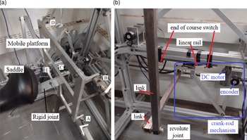
The interaction between the structure and the user is made by a saddle, as shown in Figs. 5 and9(a). This seat shape was chosen based on studies carried out in refs. [Reference Gonçalves and Krebs28]–[Reference Goncalves, Hamilton, Ali and Krebs31] that showed the best comfortable shape to support the patient weight. The saddle is rigidly fixed on the mobile platform, as shown in Fig. 9(a). If necessary for the safety of the patient one conventional overhead BWSS can be used to “catch” the subject, thus preventing falls. Figure 9(a) is shown the connected joints to the mobile platform, universal joints in points A, B, D, and E, and spherical joint (point C), Fig. 2.
Figure 9(b) shows the constructive elements of the motor module: crank-rod mechanism; DC motor; incremental encoder; and linear rail and end of course switch. Incremental encoders are used, and the initial position is set using the end of course switches. The leg is composed of the links, revolute joints, and the coupling joint in the mobile platform, Fig. 9(b).
Table III presents the actuation components specifications used in the built prototype. These are low-cost components available in the laboratory.
(a) Connect joints to the mobile platform and (b) details of leg 3.

5. Control design
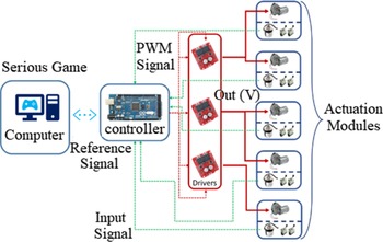
The control scheme of each actuator is represented in Fig. 10.
For each module, a controller divided into two parts was specified: a proportional integral derivative (PID)-type position controller, tuned using an optimization system based on a differential evolution algorithm, and an “assist-as-needed” (AAN) to dynamically suppress PID action, applying it only when needed by the patient. The AAN works like a check function that says whether the error is inside the dead zone. For each encoder, an interrupt-enabled, general-purpose pin was used. As described by the official microcontroller documentation, the ideal scenario for deterministic control should have two interrupt pins for each channel of each encoder. Due to the unavailability of sufficient pins, the control used a nondeterministic configuration, where the pulse count is subject to pulse losses. The equation used was as follows:
 \begin{equation} u\!\left[kT\right]=K_{p}e\!\left[kT\right]+K_{I}{\int }_{0}^{T}e\!\left[kT\right]dT+K_{d}\frac{d}{dT}e\!\left[kT\right] \end{equation}
where
 $K_{P}$
is a proportional constant,
 $K_{I}$
is an integral constant,
 $K_{D}$
is the derivative constant,
 $u[kT]$
represents the discrete output signal of the PID controller as a function of sampling time T, and
 $e[kT]$
is the system error calculated as a function of the system reference. Using a controller, it is possible to make the actuator meet design requirements, such as maximum position error
 $\varepsilon$
, settling time
 $t_{s}$
, and maximum overshoot [Reference Fadali and Visioli32]. However, due to the lack of determinism implied by the limitations of the microcontroller used, the control law of (15) is subject to variations in the sampling period T. Thus, the use of a differential evolution optimizer was necessary to guarantee stable parameters that compensated this problem. The control of the actuators was designed according to the following criteria: settling time
 $t_{s}$
less than 0.2s, overshoot close to zero, and zero stationary error.
Therefore, to estimate the parameters
 $K_{P}, K_{I}$
, and
 $K_{D}$
, it used a meta-heuristic optimization system based on a differential evolution algorithm [Reference Gonçalves, Carvalho and Lobato33]. To use this system, several tests were performed automatically in the system, analyzing the system response to a known fixed input and collecting the corresponding response telemetry of each execution. The individuals used in this algorithm had three genes, where each one represents one of the controller constants
 $K_{P}, K_{I}$
, and
 $K_{D}$
.
The controller optimization process was performed for each controller separately, following the following parameters: population size (number of individuals): 30; the maximum number of iterations (maximum generations): 30; mutation rate: 0.5%; binomial random crossing probability: 80%; side limits of variables:
 $K_{P}$
from 0.1 to 4.0;
 $K_{I}$
from 0.0 to 1.0; and
 $K_{D}$
from 0.0 to 2.0. After optimizing, the obtained results are presented in Table IV.
Actuation components specification.

Control scheme applied to the active weight support prototype.

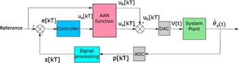
To implement the AAN behavior, an additional portion was applied to each controller according to the block diagram as shown in Fig. 11, capable of generating a zone where its action is suppressed, called “dead zone” [Reference Asl, Narikiyo and Kawanishi34]. This zone consists of a range of system error values and is empirically defined as a function of the characteristics of the controlled system, which, in the case of assisted rehabilitation, represents the region where the patient will exercise motor action without the need for a controller.
On the other hand, whenever the system error exceeds the dead zone, the controller’s control action will be applied again, representing the absence of the patient’s motor action and implying the need for intervention by the structure. The dead zone implementation is done through a combination of the controller action with a hyperbolic tangent function. The choice of this function guarantees a smooth transition between the dead zone and the controller’s action regions and weights the controller’s action to avoid sudden movements during the training session. To avoid system instabilities when the error is inside the dead zone, part of the system reference is passed directly to the control action, known as feedforward. Thus, the control action of the system is described in (16):
 \begin{equation} u_{a}[kT]=K_{P}\tanh\!(\gamma u[kT]^{3})+K_{f}\tanh\!([kT]^{3}) \end{equation}
where
 $K_{p}$
represents the proportional gain of the system,
 $u[kT]$
is the control signal of the PID controller,
 $\gamma$
is the constant used to delimit the dead zone,
 $K_{f}$
is the gain associated with the feedforward portion of the system, and
 $r[kT]$
is the system position reference.
6. Space Walker serious game
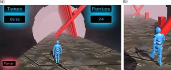
The serious game, named Space Walker, is designed to match the required characteristics to react to the movements in the training sessions with the proposed BWSS and also intends being functional and fun. Since this rehabilitation structure deals with tridimensional movements, the game was designed using the software Unity 3D with the theme of the endless runner (in which the character moves forward automatically and the user controls lateral movements moving laterally over the treadmill). The main character of the game is a humanoid robot that walks on an infinite platform with three main lanes, one to the left, one in the middle, and one to the right. During the walk, the player must avoid collisions with obstacles and collect bonus items. A screenshot of the main game interface is shown in Fig. 12(a).
Actuation components specification.

Control loop applied to actuators, including a PID controller and an AAN function.

The character humanoid robot is programmed to walk in a straight line and change lanes. Its position is hardwired to the encoder readings of
 $q_{3}$
in the proposed active BWSS. Thus, the humanoid robot should follow the same position as the user, creating an immersive sensation with the serious game.
(a) Screenshot of Space Walker showing the main character walking in the infinite platform and (b) bonus cube (green) in the scene.

The game starts with an initial screen where the health professional enters the desired duration for the training session and adjusts the translation of the mobile platform to the neutral position of the patient. After the position is adjusted, the treadmill is turned on and the game starts. The structure sends periodical data containing information about the patient’s position that controls which lane the main character should walk in. The periodical signals of the microcontroller are sent through the USB connection every 500 milliseconds, with the position of the patient along
 $Y_{0}$
measured in the rotary encoder of
 $q_{3}$
. This encoder has 500 pulses per cycle, resulting in a workspace of around 200 pulses for the motor modules.
Therefore, three zones are defined to represent the lanes of the game based on the encoder readings: up to 60 pulses, the microcontroller sends a message indicating the left lane; from 61 to 120, it indicates the central lane; and above 120 pulses, the right lane. If the player finds difficulties avoiding collisions with the obstacles, the game will send a command to activate the assistance in
 $q_{3}$
to assist the patient to move the character to the correct lane. To do this, a script counts the collisions per minute of the player, and if the value is greater or equal to 4, this command is sent to the structure. Once the collisions per minute are reduced, the assistance is turned off.
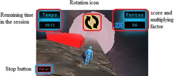
The score in the developed game is directly proportional to the time of the session, where the player continuously earns points as long as the training session is active. The game also has extra points that can be obtained by collecting bonus cubes, as shown in Fig. 12(b), or multiplying the base score when the mobile platform of the active BWSS is rotated together to rotate the scenario, as shown in Fig. 13.
The rotations of the game platform are randomly activated in an arbitrary interval between 60 and 100 s. The same command sent to the proposed BWSS is sent to the camera, creating a sensation that the same action happening in the virtual environment is being replicated in the reality. During the platform rotations, an animated icon also pops up in the game interface, as shown in Fig. 13.
Interface diagram of the platform rotation.

The bonus cubes are small floating green objects that spawn eventually with the tiles, as shown in Fig. 12(b). These cubes appear in one defined lane of the platform and are not always easily reachable. More information about the serious game developed can be found in ref. [Reference Rodrigues, Gaspar, Gonçalves, Bernardes and Amorim35].
7. Experimental tests
Experimental tests were carried out to: verification of the movements and validation of the angular amplitude of the mobile platform; verification of control requirements; validation of module resolution; and comparison of CAD/CAE model and prototype response.
7.1. Movements of the novel active BWS
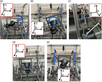
The proposed movements of the novel active BWS are presented in Fig. 14. The measurements of the mobile platform were performed using a digital inclinometer (resolution of 0.1°) to define the actual workspace of the structure and compare it with that specified in the mathematical model. In this experiment, 10 repetitions were also performed for each measured angular degree of freedom. In the case of linear degrees of freedom, the nominal measures of the linear guides applied to the structure were used as the workspace. The results are presented in Table V.
Movement tests of the mobile platform of the novel BWSS prototype. (a) Rotation in the transverse plane (about the OZ axis); (b) rotation in the frontal plane (around the OX axis); (c) translation on the OX axis; (d) translation on the OY axis; and (e) translation on the OZ axis.

From Table V, it is possible to notice that the workspace obtained in the prototype meets the proposed specifications considering the mobility of the pelvic joint. It is also noted that the selected design also allows angular amplitudes above the minimum, which will allow the structure to be used to perform controlled movements for balance training.
A comparison was made with the points obtained for one of the motors of the structure about the same movement performed by the CAD/CAE model developed [Reference Gonçalves and Rodrigues36]. In this experiment, a simulation of the mechanical system was performed moving 150 mm in 0.4 s, and the points obtained were saved. Afterward, the same movement was performed 10 times on one of the structure’s motors, and the telemetry was collected. The comparison between the simulated and experimental results is represented in Fig. 15.
7.2. Verification of control requirements
The test carried out sought to validate whether the use of the differential evolution algorithm was able to obtain the constants
 $K_{P}, K_{I}$
, and
 $K_{D}$
capable of meeting the requirements proposed in Section 5.
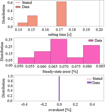
The experiment carried out consisted of saving the data recorded in the input, output, and time Arduino when performing a displacement of 200 pulses and analyzing them using open Data Science libraries in Python and Jupyter Notebooks. The results obtained are visually represented through histograms as shown in Fig. 16.
The amplitude of the mobile platform measured experimentally.

Comparison between the experimental data measured in one of the prototype actuators and the data simulated in CAD.

Histogram representing the distribution of the results obtained in the 11 repetitions of the control requirements validation experiment. From top to bottom, Settling Time Analysis Results, Percent Stationary Error, and Overshoot.

Through the visual analysis of the collected data, it was possible to notice that the specified accommodation time was consistently met, ensuring that the system presents an adequate response. Although the stationary error has been specified as null and the mechanical characteristics of the system guarantee a transfer function with Type Number 1, the error cannot be eliminated. This error will need to be investigated in detail in future works and may be linked to the limitations of the microcontroller. However, considering the constructive aspects of the structure, the stationary error of the structure can still be considered tolerable and not cause significant problems in the movement of the platform, guaranteeing the functionality of the equipment. In addition, the system did not show overshoot in any of the samples. This also ensures that frame-specified movements will not expose patients to an excessive range of motion and will prevent vibrations when reaching the desired position.
Another experiment carried out sought to validate the relationship between the number of pulses measured in the encoders. To carry out this experiment, a displacement of 200 pulses was applied to each of the motors with 10 repetitions, and the displacement of the linear cursor was measured with the aid of a precision ruler (resolution of 0.5 mm) fixed below the cursor rail. The results obtained are graphically represented in Fig. 17.
Boxplot graph of the resolution calculated for each actuator, in pulses/mm.

It is noteworthy that as one of the actuators used an encoder with 500 pulses per revolution, it obtained a lower resolution than the others. The resolution presented a considerable variance in all cases which is connected with the mechanical and electronic limitations of the prototype. However, it was possible to observe that the resolutions remain close to each other in actuators with 600-pulse encoders, and within the expected value according to the mathematical model obtained in Section 3. With an estimated value for the resolution, it was also possible to estimate the maximum linear velocity reached by the modules, equal to approximately 1.29 m/s.
Therefore, based on the results obtained in the experiments, it can be concluded that the structure is valid for the practical tests foreseen with healthy patients.
7.3. Pilot study
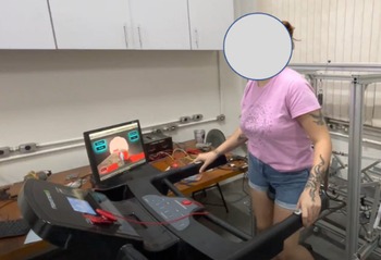
Experimental trials have been approved by the ethics committee on human research at the Federal University of Uberlândia (CAAE 01305318.2.0000.5152). The tests were made using the proposed novel BWS in combination with the developed serious game and a treadmill. All participants gave their informed consent before enrollment. The trial was carried out on two healthy volunteers over 18 years of age, one male and the other female. The proposed objectives for the trial are as follows: check the operation of the structure together with the treadmill in operation, with the human gait running; check the control of the position of the main character of the game, during the execution of the human gait; evaluate gameplay and difficulty during actual use; and identify electrical and/or mechanical failures during operation. Two test sessions lasting about 5 min were performed. A photograph of one test session is shown in Fig. 18.
Test session with the healthy participant.

The neutral position of the platform was adjusted according to the height of each participant. Then, the participants were accommodated on the structure, and the treadmill was turned on. Participants walked on the treadmill for a few minutes without the game running to check if the speed was adequate, and the platform was comfortable. After confirming the initial conditions with the participants, the game was started and the test session was video-recorded. At the end of the session, the recordings were interrupted and the volunteers presented their main impressions of the structure and the serious game.
The first feedback presented by the participants was about the execution of the gait on the treadmill with the platform. Both participants reported being able to walk normally, with little or no influence of the saddle on the movements performed. During the game, participants reported little difficulties in properly moving the character just moving to the left or right of the treadmill. The main causes of this problem were the limited space for lateral displacement. As for the gameplay of the game, the participants contributed to the correction of the position of some obstacles and the bonus cube. In the game event of platform inclination, the participants reported that the displacement was noticeable, being necessary to adjust the gait movements to the imposed position. The video footage of the experimental tests and the computational simulations presented in this paper can be accessed in: https://drive.google.com/drive/folders/17bZKsnUAPb1jSSVaHco1ahpjLiTBqhZM?usp=sharing
8. Conclusion
This article has reported the design and operation of a novel active BWS device for gait rehabilitation as the main contribution. The proposed device is a parallel structure with a low level of coupling in the movements, and the analysis of singularities demonstrated a workspace without singular positions. In this way, the structure can be controlled more simply and with actuators more independent of each other, despite the closed-chain configuration, and the optimization of dimensions was not restricted in terms of singular positions. Furthermore, the device was developed to be low cost with the objective of use in low-income countries.
Attention is addressed to its control architecture and its integration in a specifically developed serious game software, which is the objective of stimulating patient interactions. The actuators of the structure were controlled after applying an optimization by differential evolution to obtain the best control parameters for each actuator. In this way, it was possible to compensate for the nonlinearities and unforeseen factors during the actuator modules’ construction process and control the motors. In addition, an assist-as-needed function was applied to enable the patient’s motor action without the interference of the equipment when not necessary.
The experimental tests were carried out in the novel active BWS device, integrated into the developed game. The experimental tests demonstrated some constructive aspects to be improved in the structure to offer a better experience during the training sessions. Based on tests carried out with healthy volunteers, it was possible to obtain recommendations for improvements to the main character’s control system, assembly of the physical structure, assembly of actuators, and adjustments in the serious game.
For the control of the structure, it is recommended to use, in future works, machine learning to obtain and evaluate the trajectory profile of the healthy human gait in the telemetry of the structure and to control the dead zone of the AAN as a function of deviations observed in this profile. Also, a suggestion for future work is the use of a haptic virtual environment. The next step is to realize clinical tests with poststroke patients.
Accordingly, the proposed device has been submitted for patenting, and it can be further investigated as a tool to assist professionals in procedures of gait rehabilitation.
Author contributions
The authors contributed equally for the preparation of the paper.
Financial support
This work was supported in part by CNPq under Grant 03511/2021-4, CAPES (Finance code 001), and FAPEMIG under Grant APQ-02829-17.
Conflicts of interest
The authors declare no conflicts of interest exist.
Ethical approval
Experimental trials have been approved by the ethics committee on human research at the Federal University of Uberlândia (CAAE 01305318.2.0000.5152).