



1 Introduction
Capsules, which consist of a thin deformable membrane around a liquid droplet, play the joint role of transporting and protecting an inner fluid content. The principle of microencapsulation is ubiquitous with many applications in industry. Besides its classical use in inkjet printing, photography, cosmetic cream manufacturing, etc., it is at the source of innovative applications, many of them appearing in the field of biotechnologies (Ma & Su Reference Ma and Su2013). For instance, contrast-enhanced ultrasound has become one of the most widespread imaging techniques thanks to the use of coated air microbubbles or of microcapsules filled with perfluorinated gases for echogenicity (Furlow Reference Furlow2009). In pharmaceutics, drug and cell encapsulation is rapidly developing (Bhujbal, de Vos & Niclou Reference Bhujbal, de Vos and Niclou2014) and has led to new treatment techniques, such as targeted drug therapy. Similarly, encapsulation is used for the development of bioartificial organs (e.g. encapsulation of islets of Langerhans for diabetic patients (Clayton, James & London Reference Clayton, James and London1993) or of haemoglobin to create artificial blood (Chang Reference Chang2003)). Many instances of encapsulation may also be found in nature (e.g. seeds, eggs, cells). Red blood cells (RBC) are an example of natural capsules: their two-layer membrane is composed of a lipid bilayer (outer layer) and a cytoskeleton which protects a solution of haemoglobin (Mohandas & Gallagher Reference Mohandas and Gallagher2008).
The motion of spheroidal capsules in simple shear flow with shear rate
 $\dot{{\it\gamma}}$
is quite complicated. It depends on the axis ratio
 $a/b$
, (where
 $a$
and
 $b$
are the half-diameters along the revolution and azimuthal axes, respectively), on the viscosity ratio
 ${\it\lambda}$
between the internal and external liquids and on the relative flow strength measured by the capillary number
 $Ca={\it\mu}\dot{{\it\gamma}}\ell /G_{s}$
, where
 ${\it\mu}$
is the suspending fluid viscosity,
 $G_{s}$
the surface shear elastic modulus of the capsule membrane and
 $\ell$
the length scale defined as the radius of the sphere with the same volume as the capsule. Different behaviours have been identified. When the capsule revolution axis is in the shear plane, the particle can rotate like a quasi-solid particle (tumbling motion), or it can take a deformed shape where the long axis oscillates around a mean orientation in the shear plane, while the membrane rotates about the deformed shape (swinging or tank-treading motion, depending on the oscillation amplitude). Another equilibrium state is found when the particle revolution axis is perpendicular to the shear plane (i.e. aligned with the vorticity axis): the capsule takes a rolling motion and rotates like a (deformed) wheel under the flow vorticity. The rolling motion is also referred to as the
 $C=0$
orbit in reference to Jeffery (Reference Jeffery1922)’s work. The transition from in-plane to rolling motion has received many names in the literature: wobbling, precessing, kayaking, oscillating–swinging.
No experiment has ever been conducted on artificial ellipsoidal capsules with large deviation from isotropy (i.e. with
 $a/b<0.9$
or
 $a/b>1.1$
) due to the current absence of robust techniques to fabricate them. The only slightly ellipsoidal capsules that exist are imperfect spherical ones: their aspect ratio is thus typically close to 1. Experiments on such capsules have shown that their dynamics are very different from those observed for a rigid particle or even a spherical capsule. They have proven the existence of the tumbling regime at low
 $Ca$
and the transition towards swinging at larger
 $Ca$
(Chang & Olbricht Reference Chang and Olbricht1993; Walter, Rehage & Leonhard Reference Walter, Rehage and Leonhard2001).
For obvious physiological reasons, there are many experimental observations of the motion of RBCs, which can be considered as easily obtainable ‘ready-made’ (biconcave) oblate capsules. Note though, that the RBC membrane is very different from the polymerized membrane of a typical artificial capsule. At low shear rate, an RBC has a tumbling motion, which evolves into a swinging motion as the shear rate increases (Abkarian, Faivre & Viallat Reference Abkarian, Faivre and Viallat2007; Abkarian & Viallat Reference Abkarian and Viallat2008; Fischer & Korzeniewski Reference Fischer and Korzeniewski2013), similarly to what has been found for artificial capsules. However, it was shown that RBCs may also drift into a
 $C=0$
orbit. Goldsmith & Marlow (Reference Goldsmith and Marlow1972) were the first to show that an increasing number of cells tended to drift and align their axis of symmetry with the vorticity axis, as the flow strength was increased. This phenomenon was further studied by Bitbol (Reference Bitbol1986) and Dupire, Socol & Viallat (Reference Dupire, Socol and Viallat2012), and quantified by Yao et al. (Reference Yao, Wen, Yan, Sun, Ka, Xie and Chien2001). They have shown that the tumbling motion becomes unstable so that the RBCs take a rolling motion, before switching to tank-treading. Note that RBCs have complex properties: they are biconcave, have a multi-component membrane with viscoelasticity and bending rigidity, as well as a pre-stress within the membrane because of the cell reference shape. It is not quite clear which of these properties influences the transition from one motion to the other.
It is then of interest to study whether similar transitions would exist for simpler particles, such as oblate capsules with a hyperelastic membrane. The object of the present manuscript is to conduct a numerical study of the three-dimensional motion of oblate capsules in simple shear flow to provide an answer to this question.
A number of numerical studies have investigated the dynamics of a spheroidal capsule placed in a simple shear flow. The first models considered the case where the revolution axis of the capsule is placed in the shear plane (Ramanujan & Pozrikidis Reference Ramanujan and Pozrikidis1998; Kessler, Finken & Seifert Reference Kessler, Finken and Seifert2008; Sui et al.
Reference Sui, Low, Chew and Roy2008; Bagchi & Kalluri Reference Bagchi and Kalluri2009; Le & Tan Reference Le and Tan2010; Walter, Salsac & Barthès-Biesel Reference Walter, Salsac and Barthès-Biesel2011): it is then bound to remain in it, as the flow is governed by Stokes’ equations. It was found that the capsule has a tumbling motion at low
 $Ca$
and a swinging motion at high
 $Ca$
, and that the capsule assumes a quasi-circular shape in the shear plane at the tumbling-to-swinging transition (Walter et al.
Reference Walter, Salsac and Barthès-Biesel2011). Walter et al. (Reference Walter, Salsac and Barthès-Biesel2011) showed that the value of
 $Ca$
at the transition depends on the capsule aspect ratio, the transition occurring at higher
 $Ca$
for prolate capsules than for oblate capsules, and that increasing the internal viscosity shifts the transition to higher values of
 $Ca$
for a given capsule shape.
The off-plane motion of a prolate capsule has been recently studied in simple shear flow in Stokes flow conditions by Dupont, Salsac & Barthès-Biesel (Reference Dupont, Salsac and Barthès-Biesel2013) or under low flow inertia (Reynolds number
 $Re=0.2$
) by Cordasco & Bagchi (Reference Cordasco and Bagchi2013) and Wang et al. (Reference Wang, Sui, Spelt and Wang2013). Dupont et al. (Reference Dupont, Salsac and Barthès-Biesel2013) have considered flow strengths
 $0.1\leqslant Ca\leqslant 2$
. They have found that the low
 $Ca$
tumbling motion in the shear plane is mechanically unstable: starting from any initial orientation, the capsule eventually places its revolution axis along the vorticity axis and takes a stable rolling motion. As
 $Ca$
is increased, a prolate capsule tilts away from the vorticity axis and precesses around it. At still higher values of
 $Ca$
, a stable swinging regime is observed, where the capsule longest axis tends towards the shear plane. Dupont et al. (Reference Dupont, Salsac and Barthès-Biesel2013) have shown that these stable equilibrium states do not depend on the initial orientation of the capsule, a result which is confirmed by Wang et al. (Reference Wang, Sui, Spelt and Wang2013) for
 $Ca\geqslant 0.03$
. The fact that Cordasco & Bagchi (Reference Cordasco and Bagchi2013) find that the motion depends on the initial capsule orientation may be due to too short computation times.
The question that arises is whether the results found for prolate capsules apply to oblate spheroidal capsules. Cordasco & Bagchi (Reference Cordasco and Bagchi2013) studied oblate ellipsoidal capsules for
 $0.05\leqslant Ca\leqslant 0.6$
, different axis ratios and no viscosity contrast (
 ${\it\lambda}=1$
). They conclude that an oblate spheroidal capsule always tends towards the shear plane where it takes a tumbling or swinging motion with oscillations about the shear plane (also called kayaking) depending on
 $Ca$
. They only identified a tendency towards rolling, when modelling RBCs with larger values of the internal viscosity. Their conclusions are based on the trend of the evolution curves, as too short computational times are used in the simulations to observe the converged regimes. Wang et al. (Reference Wang, Sui, Spelt and Wang2013) considered oblate capsules with an axis ratio of
 $2/3$
for
 $0.003\leqslant Ca\leqslant 0.3$
and
 ${\it\lambda}=1$
. They also found for
 $Ca\geqslant 0.03$
that the capsule tends towards the shear plane where it takes a tumbling or oscillating–swinging motion, but all of their results depend on the capsule initial orientation. The occurrence of a rolling regime at higher capillary number has so far only been found for an oblate capsule by Omori et al. (Reference Omori, Imai, Yamaguchi and Ishikawa2012). In their study, they examined capsules with
 $a/b=0.4$
and 0.6 for
 $0.01\leqslant Ca\leqslant 2$
. They showed that the transitions from swinging to wobbling and from wobbling to rolling strongly depend on the aspect ratio and constitutive law and that these occur for lower values of the capillary number when the viscosity ratio is increased from 0.5 to 2.
Previous results thus indicate that the dynamics of prolate and oblate capsules are very different. If the dynamics of prolate spheroidal capsules are rather well understood, such is not the case for oblate ones, for which a comprehensive study has still to be performed. A number of pending questions remain:
-
(i) Does the final motion of an oblate capsule depend on the initial orientation?
-
(ii) Is rolling the high flow strength motion when the capsule is oblate?
-
(iii) How are the capsule dynamics affected by the internal viscosity when the latter is greater than 1?
-
(iv) How long does it take for a capsule to reach an equilibrium configuration?
The present work aims at finding the stable equilibrium configurations and studying the influence of the capillary number, aspect ratio and viscosity ratio. Experimentally, the external viscosity is indeed rarely matched with the viscosity of the internal fluid. In particular, we will show that the final equilibrium motion of an oblate capsule does not depend on its initial orientation, in contrast with previous conclusions. Another important objective is to determine the time required for an oblate capsule initially placed off the shear plane to reach its mechanical equilibrium state. Such information is crucial when setting up experiments to observe the behaviour of oblate capsules. Specifically, it is important to make sure that the observed motion is steady. Similarly, this information should also be useful to choose adequately the proper computational times of numerical models.
To solve the fluid–structure interaction problem, we use the numerical model developed by Walter et al. (Reference Walter, Salsac, Barthès-Biesel and Le Tallec2010) and Foessel et al. (Reference Foessel, Walter, Salsac and Barthès-Biesel2011), based on the coupling of a membrane finite element method for the capsule deformation with a boundary integral method for the internal and external flows. We briefly outline the problem and the numerical method in § 2. The equilibrium configurations of an oblate capsule initially positioned off the shear plane are studied in § 3 as well as the influence of the aspect ratio and viscosity ratio between the internal and external flow. The characteristic times to reach equilibrium are evaluated in § 4 as a function of the viscosity ratio, before discussing all the results in § 5.
2 Method
2.1 Problem statement and numerical method
We consider a capsule with a very thin membrane, modelled as an isotropic hyperelastic surface
 $S_{t}$
with surface shear modulus
 $G_{s}$
, area dilatation modulus
 $K_{s}$
and negligible bending resistance. In the reference undeformed state, the capsule is an oblate spheroid with aspect ratio
 $a/b$
, where
 $a$
denotes the half-diameter along the revolution axis, and
 $b$
the half-diameter along any orthogonal direction. The problem length scale
 $\ell =(ab^{2})^{1/3}$
is defined as the radius of the sphere with the same volume as the capsule. Unless otherwise stated, we will consider a capsule with
 $a/b=1/2$
, for which
 $a/\ell =0.63$
and
 $b/\ell =1.26$
.
We define the reference frame
 ${\mathcal{F}}^{\prime }(O,\boldsymbol{e}_{x}^{\prime },\boldsymbol{e}_{y}^{\prime },\boldsymbol{e}_{z}^{\prime })$
, where
 $O$
is the capsule centre of mass and
 $\boldsymbol{e}_{x}^{\prime }$
,
 $\boldsymbol{e}_{y}^{\prime }$
,
 $\boldsymbol{e}_{z}^{\prime }$
are the principal axes of the undeformed capsule. The revolution axis is initially along
 $\boldsymbol{e}_{z}^{\prime }$
, so that the initial capsule profile is given by
 $$\begin{eqnarray}\left(\frac{x^{\prime }}{b}\right)^{2}+\left({\displaystyle \frac{y^{\prime }}{b}}\right)^{2}+\left(\frac{z^{\prime }}{a}\right)^{2}=1,\end{eqnarray}$$
where the coordinates
 $(x^{\prime },y^{\prime },z^{\prime })$
correspond to the position of a material point on the membrane.
The capsule is suspended in an unbounded Newtonian incompressible fluid of viscosity
 ${\it\mu}$
. The inner fluid is also Newtonian and incompressible with viscosity
 ${\it\lambda}{\it\mu}$
, where
 ${\it\lambda}$
is the internal-to-external viscosity ratio. The density of the internal and surrounding fluids are equal, thus excluding gravity effects. The Reynolds number of the flow is assumed to be negligible, so that the internal and external flows are governed by Stokes’ equations. The capsule is subjected to a simple shear flow with shear rate
 $\dot{{\it\gamma}}$
given by
 $$\begin{eqnarray}\boldsymbol{v}^{\infty }=\dot{{\it\gamma}}y\boldsymbol{e}_{x}\end{eqnarray}$$
in the laboratory reference frame
 ${\mathcal{F}}(O,\boldsymbol{e}_{x},\boldsymbol{e}_{y},\boldsymbol{e}_{z})$
.
At time
 $\dot{{\it\gamma}}t=0$
, the capsule orientation in space is defined by the angles between the basis vectors of the reference frames
 ${\mathcal{F}}^{\prime }$
and
 ${\mathcal{F}}$
. The capsule revolution axis
 $\boldsymbol{e}_{z}^{\prime }$
makes an angle
 ${\it\zeta}(0)$
with the vorticity axis, such that
 $(\boldsymbol{e}_{z}^{\prime },\boldsymbol{e}_{z})=(\boldsymbol{e}_{y}^{\prime },\boldsymbol{e}_{y})={\it\zeta}(0)$
and
 $(\boldsymbol{e}_{x}^{\prime },\boldsymbol{e}_{x})=0$
(figure 1
a). Thus
 ${\it\zeta}(0)=0$
or
 ${\rm\pi}/2$
corresponds to a capsule with its revolution axis parallel to the vorticity axis or to the shear plane, respectively.
Reference (a) and deformed (b) configurations of an oblate capsule subjected to a simple shear flow. The initial capsule orientation is defined by the angle
 ${\it\zeta}(0)$
between the capsule revolution axis
 $\boldsymbol{e}_{z}^{\prime }$
and the flow vorticity axis
 $\boldsymbol{e}_{z}$
. The points
 $M_{i}(t)$
represent the tip of the capsule principal axes and the points
 $A_{i}(t)$
are the points initially located at the tip of the capsule principal axes.

The problem is solved numerically using the boundary integral–finite element method (BI–FE) (Foessel et al. Reference Foessel, Walter, Salsac and Barthès-Biesel2011). This method couples a boundary integral technique to compute the fluid flows (inside and outside the capsule) to a finite element method to compute the capsule membrane deformation. The method is summarized in this section, but more details are available in Barthès-Biesel, Walter & Salsac (Reference Barthès-Biesel, Walter and Salsac2010), Walter et al. (Reference Walter, Salsac, Barthès-Biesel and Le Tallec2010) and Foessel et al. (Reference Foessel, Walter, Salsac and Barthès-Biesel2011).
The numerical procedure is based on a Lagrangian tracking of the position of the membrane material points of
 $S_{t}$
. The capsule deformation and in-plane principal stretch ratios
 ${\it\lambda}_{1}$
and
 ${\it\lambda}_{2}$
may thus be computed from the position of the membrane points at each time. The capsule wall is assumed to be strain hardening and to follow a Skalak law (Skalak et al.
Reference Skalak, Tozeren, Zarda and Chien1973). The principal elastic tensions
 $T_{1}$
and
 $T_{2}$
, which are forces per unit length of deformed membrane, are then given by
 $$\begin{eqnarray}T_{1}={\displaystyle \frac{G_{s}}{{\it\lambda}_{1}{\it\lambda}_{2}}}[{\it\lambda}_{1}^{2}({\it\lambda}_{1}^{2}-1)+C({\it\lambda}_{1}{\it\lambda}_{2})^{2}(({\it\lambda}_{1}{\it\lambda}_{2})^{2}-1)],\end{eqnarray}$$
with a corresponding expression for
 $T_{2}$
obtained by permuting indices 1 and 2. The surface shear and area dilatation moduli are then related by
 $K_{s}=G_{s}(1+2C)$
, where
 $C$
is a constant such that
 $C>-1/2$
.
The finite element method is used to solve the equilibrium equation of the membrane
 $$\begin{eqnarray}\boldsymbol{{\rm\nabla}}_{s}\boldsymbol{\cdot }\boldsymbol{T}+\boldsymbol{q}=\mathbf{0}\end{eqnarray}$$
in its weak form and to find the load
 $\boldsymbol{q}(\boldsymbol{x},\boldsymbol{t})$
exerted by the fluids on the membrane at time
 $t$
. In (2.4), the symbol
 $\boldsymbol{{\rm\nabla}}_{s}$
represents a surface gradient.
Knowing the viscous load
 $\boldsymbol{q}$
, the velocity
 $\boldsymbol{v}(\boldsymbol{x},t)$
of the membrane points is deduced from a boundary integral formulation for the three-dimensional motion of the internal and external fluids
 $$\begin{eqnarray}\displaystyle \boldsymbol{v}(\boldsymbol{x},t) & = & \displaystyle \boldsymbol{v}^{\infty }(\boldsymbol{x})-{\displaystyle \frac{1}{8{\rm\pi}{\it\mu}}}\int _{S_{t}}\left({\displaystyle \frac{\unicode[STIX]{x1D644}}{\Vert \boldsymbol{r}\Vert }}+{\displaystyle \frac{\boldsymbol{r}\otimes \boldsymbol{r}}{\Vert \boldsymbol{r}\Vert ^{3}}}\right)\boldsymbol{\cdot }\boldsymbol{q}(\boldsymbol{y},t)\,\text{d}S(\boldsymbol{y})\nonumber\\ \displaystyle & & \displaystyle -\,\frac{1-{\it\lambda}}{8{\rm\pi}}\int _{S_{t}}\left(\boldsymbol{v}(\boldsymbol{y},t)-\boldsymbol{v}(\boldsymbol{x},t)\right)\boldsymbol{\cdot }{\displaystyle \frac{\boldsymbol{r}\otimes \boldsymbol{r}\otimes \boldsymbol{r}}{\Vert \boldsymbol{r}\Vert ^{5}}}\boldsymbol{\cdot }\boldsymbol{n}(\boldsymbol{y})\,\text{d}S(\boldsymbol{y}),\end{eqnarray}$$
where
 $\boldsymbol{v}^{\infty }$
is given by (2.2),
 $\unicode[STIX]{x1D644}$
is the identity tensor,
 $\boldsymbol{n}$
is the unit vector normal to
 $S_{t}$
and
 $\boldsymbol{r}=\boldsymbol{x}-\boldsymbol{y}$
is the distance between the point
 $\boldsymbol{x}$
where the calculation is performed and the point of integration
 $\boldsymbol{y}$
. The new position of the membrane points at the next time step is found by using an explicit second-order Runge–Kutta method to solve the kinematic condition, which relates the membrane velocity to the time derivative of the Lagrangian position of the membrane points
 $$\begin{eqnarray}\boldsymbol{v}(\boldsymbol{x},t)=\frac{\partial \boldsymbol{x}(\boldsymbol{X},t)}{\partial t},\quad \boldsymbol{x}\in S_{t},\end{eqnarray}$$
where
 $\boldsymbol{X}$
represents the position of a point in the reference configuration.
In general, the capsule motion and deformation are governed by:
-
(i) the capsule initial orientation
 ${\it\zeta}(0)$
;
-
(ii) the capsule aspect ratio
$a/b$
; -
(iii) the membrane constitutive law;
-
(iv) the ratio of the area dilatation and shear moduli
$K_{s}/G_{s}$
; -
(v) the capillary number
$Ca={\it\mu}\dot{{\it\gamma}}\ell /G_{s}$
, which measures the ratio between the viscous and the elastic forces; and -
(vi) the viscosity ratio
${\it\lambda}$
.


We assume that the capsule membrane follows the Skalak law with
 $C=1$
(for which
 $K_{s}/G_{s}=3$
) and study the influence of
 ${\it\zeta}(0)$
,
 $Ca$
,
 $a/b$
and
 ${\it\lambda}$
on the capsule dynamics.
2.2 Discretization, stability and convergence
One of the advantages of the BI–FE method is that all the problem unknowns are to be determined on the capsule surface and not in the entire domain volume. The capsule surface is meshed by subdividing sequentially the 20 triangular faces of an icosahedron inscribed in a sphere until the desired number of elements is reached. Nodes are then added at the middle of all the element edges and projected onto the sphere in order to generate second-order
 $P_{2}$
elements. This mesh is deformed into an ellipsoidal mesh with the desired axis ratio (Walter et al.
Reference Walter, Salsac and Barthès-Biesel2011). All the results are shown for a mesh with 2562 nodes and 1280 triangular curved elements.
The numerical method is stable when the time step satisfies the condition
 $$\begin{eqnarray}\dot{{\it\gamma}}\triangle t<O\left(\frac{{\rm\Delta}xCa}{\ell }\right),\end{eqnarray}$$
where
 ${\rm\Delta}x$
is the typical mesh size (Walter et al.
Reference Walter, Salsac, Barthès-Biesel and Le Tallec2010). Here,
 ${\rm\Delta}x=0.075$
. We use
 $\dot{{\it\gamma}}\triangle t=5\times 10^{-3}$
for
 $Ca\geqslant 0.5$
and decrease the time step proportionally for lower
 $Ca$
.
To reach the steady state of a capsule initially off the plane, computational times of the order of
 $\dot{{\it\gamma}}t=10^{2}{-}10^{3}$
are needed. In order to estimate the numerical error over such long computational times, we compute the relative error
 ${\it\epsilon}_{V}=|V-V_{0}|/V_{0}$
on the capsule volume
 $V$
, where
 $V_{0}$
is the initial volume of the capsule. The error at
 $\dot{{\it\gamma}}t=100$
is
-
(i)
$\mathit{O}(10^{-2})$
for
${\it\lambda}<4$
and
$Ca\leqslant 0.6$
, -
(ii)
$\mathit{O}(10^{-3})$
for
${\it\lambda}<4$
and
$Ca>0.6$
and for all the values of
$Ca$
for
${\it\lambda}\geqslant 4$
.


2.3 Result analysis
The capsule motion in space is complex. We characterise it by simultaneously studying the overall shape evolution (Eulerian description) and the motion of the membrane material points (Lagrangian tracking).
The global geometry of the capsule is evaluated by means of the ellipsoid of inertia of the deformed shape, with principal axes denoted
 $L_{i}(t)$
(
 $i=1,2,3$
) such that
 $L_{1}(t)>L_{2}(t)>L_{3}(t)$
at time
 $t$
. The corresponding unit principal vectors in
 ${\mathcal{F}}$
are
 $\boldsymbol{u}_{i}(t)$
(
 $\boldsymbol{u}_{1}(0)=\boldsymbol{e}_{x}^{\prime }$
,
 $\boldsymbol{u}_{2}(0)=\boldsymbol{e}_{y}^{\prime }$
and
 $\boldsymbol{u}_{3}(0)=\boldsymbol{e}_{z}^{\prime }$
). The capsule position in space is then determined from the angle
 ${\it\zeta}(t)=(\boldsymbol{u}_{3}(t),\boldsymbol{e}_{z})$
between the capsule small axis and the vorticity direction (figure 1
b). We also follow the motion in time of the point
 $M_{3}(t)$
, which corresponds to the intersection between the small axis direction
 $\boldsymbol{u}_{3}(t)$
and the membrane.
The membrane rotation is deduced from the motion in time of the points
 $A_{i}(t)$
, which were initially located on the intersections between the
 $\boldsymbol{u}_{i}(0)$
directions and the membrane (figure 1). We will for instance compare the motions of the points
 $A_{3}(t)$
and
 $M_{3}(t)$
in order to analyse eventual membrane rotation. We denote
 ${\it\xi}(t)=(\boldsymbol{O}\boldsymbol{A}_{3}(t),\boldsymbol{e}_{z})$
the angle between the
 $\boldsymbol{O}\boldsymbol{A}_{3}(t)$
and the vorticity axis (figure 1
b). At time
 $\dot{{\it\gamma}}t=0$
, the points
 $A_{3}(0)$
and
 $M_{3}(0)$
are superimposed, so that
 ${\it\xi}(0)={\it\zeta}(0)$
.
3 Stable equilibrium configurations
3.1 Equilibrium configurations of a capsule with
${\it\lambda}=1$

3.1.1 Obvious equilibrium positions
Two obvious equilibrium configurations exist for an oblate capsule placed in a shear flow under Stokes flow conditions: when the capsule revolution axis is initially in the shear plane or perpendicular to it.
Capsule shape evolution over one half-period at steady state when
 ${\it\xi}(0)=90^{\circ }$
(
 ${\it\lambda}=1$
). The grey scale corresponds to the normal component of the load
 $\boldsymbol{q}\boldsymbol{\cdot }\boldsymbol{n}$
on the membrane, with maximum values depending on
 $Ca$
. (a)
 $Ca=0.01$
: tumbling regime
 $(\max (\boldsymbol{q}\boldsymbol{\cdot }\boldsymbol{n}/G_{s})=0.15)$
; (b)
 $Ca=0.3$
: swinging regime
 $(\max (\boldsymbol{q}\boldsymbol{\cdot }\boldsymbol{n}/G_{s})=2)$
; (c)
 $Ca=1.5$
: quasi-steady tank-treading regime
 $(\max (\boldsymbol{q}\boldsymbol{\cdot }\boldsymbol{n}/G_{s})=6)$
. The value of the non-dimensional time
 $\dot{{\it\gamma}}t$
is given below each shape. The points
 $A_{1}(t)$
(▪) and
 $A_{3}(t)$
(●) are initially on the long and short axes respectively in the shear plane. The point
 $M_{3}(t)$
(▵) represents the tip of the smallest capsule principal axis (see figure 1).

When the capsule revolution axis is initially in the shear plane (
 ${\it\zeta}(0)={\it\xi}(0)=90^{\circ }$
,
 $A_{3}(0)$
and
 $M_{3}(0)$
in the shear plane), we have seen in the introduction that the capsule experiences tumbling at low
 $Ca$
followed by a transition towards swinging for higher values of
 $Ca$
. Figure 2 illustrates the characteristic dynamics of the capsule during half a period in both regimes (see Walter et al. (Reference Walter, Salsac and Barthès-Biesel2011) for more details). In this case, the points
 $A_{3}(t)$
and
 $M_{3}(t)$
remain in the shear plane for all the values of
 $Ca$
and time (
 ${\it\zeta}(t)={\it\xi}(t)=90^{\circ }$
).
When the capsule revolution axis is initially along the vorticity axis (
 ${\it\zeta}(0)={\it\xi}(0)=0^{\circ }$
,
 $A_{3}(0)$
and
 $M_{3}(0)$
on the vorticity axis), the capsule cross-sections parallel to the shear plane are initially circular. They are deformed by the shear flow and the membrane rotates around the deformed shape. This capsule motion is called rolling, since the membrane rotates around the cross-section like a deformed wheel. At low
 $Ca$
(figure 3
a), the capsule cross-section is not much deformed so that the points
 $M_{3}$
and
 $A_{3}$
remain on the vorticity axis (
 ${\it\zeta}(t)={\it\xi}(t)=0^{\circ }$
). As the capillary number increases, the cross-section elongates in the straining direction (figure 3
b): the capsule small axis
 $\boldsymbol{u}_{3}$
and hence the point
 $M_{3}$
may eventually become located in the shear plane, while the point
 $A_{3}$
remains on the vorticity axis. In this case, the asymptotic values of the angles are
 ${\it\zeta}(t)=90^{\circ }$
and
 ${\it\xi}(t)=0^{\circ }$
.
Note that for large
 $Ca$
, the oscillation amplitude of the swinging regime observed when
 ${\it\zeta}(0)=90^{\circ }$
tends to zero so that the capsule experiences a quasi tank-treading motion (figure 2
c). This regime is visually the same as the rolling motion observed when
 ${\it\zeta}(0)=0^{\circ }$
at large
 $Ca$
(figure 3
b). The only way to distinguish between the two regimes is by monitoring the position of the point
 $A_{3}$
and the angle
 ${\it\xi}(t)$
. This shows that the best parameter to study the capsule motion is the angle
 ${\it\xi}(t)$
. Experimentally, it can be achieved by attaching markers to the membrane, but this is difficult to perform. Resorting to numerical simulations is thus useful to distinguish between those regimes.
Capsule shape evolution over one half-period at steady state when
 ${\it\zeta}(0)=0^{\circ }$
(
 ${\it\lambda}=1$
): capsule in rolling regime. (a)
 $Ca=0.01$
(
 $\max (\boldsymbol{q}\boldsymbol{\cdot }\boldsymbol{n}/G_{s})=0.1$
); (b)
 $Ca=1.5$
(
 $\max (\boldsymbol{q}\boldsymbol{\cdot }\boldsymbol{n}/G_{s})=5$
). Same legend as in figure 2. The points
 $A_{3}(t)$
and
 $M_{3}(t)$
are superimposed in (a), whereas
 $A_{3}(t)$
is on the vorticity axis and
 $M_{3}(t)$
is in the shear plane in (b).

3.1.2 Stable equilibrium of an initially off-plane capsule
In Stokes flow, the mechanical stability of an equilibrium configuration can only be tested by perturbing the capsule orientation, which corresponds here to positioning the revolution axis with an initial orientation
 ${\it\xi}(0)={\it\zeta}(0)\in \, ]\,0^{\circ },90^{\circ }[\,$
. We then follow the time evolution of the angles
 ${\it\zeta}(t)$
(to determine the overall capsule position) and
 ${\it\xi}(t)$
(to determine the type of capsule motion). Note that if
 ${\it\xi}(t)\rightarrow 90^{\circ }$
, the capsule tends towards the tumbling or the swinging regime (§ 3.1.1). On the other hand, if
 ${\it\xi}(t)\rightarrow 0^{\circ }$
, the capsule stable configuration is the rolling motion. If
 ${\it\xi}(t)$
and
 ${\it\zeta}(t)$
tend towards any other value in
 $]\,0,90^{\circ }[\,$
, the capsule takes at equilibrium a wobbling motion, where it precesses and oscillates about the vorticity axis.
We first investigate whether the initial orientation affects the final equilibrium configuration. We start by considering a weak flow strength (
 $Ca=0.01$
) and three different initial orientations (
 ${\it\zeta}(0)={\it\xi}(0)=5^{\circ }$
,
 $45^{\circ }$
,
 $75^{\circ }$
). As shown in figure 4(a), the angles
 ${\it\zeta}(t)$
and
 ${\it\xi}(t)$
both tend to
 $90^{\circ }$
independently of the initial orientation. The only effect of the initial position is the time it takes to reach equilibrium, which increases the further the capsule is initially from its final equilibrium position. For
 $Ca=0.01$
, the stable equilibrium regime is a quasi-solid tumbling motion (with no membrane rotation), which explains why the curves of
 ${\it\zeta}(t)$
and
 ${\it\xi}(t)$
are superimposed. For a larger flow strength
 $Ca=0.3$
, the angles
 ${\it\zeta}(t)$
and
 ${\it\xi}(t)$
both converge towards
 $90^{\circ }$
but do not follow the same time evolution during the transition phase (figure 4
b). During the transient phase, the capsule takes a global oscillating swinging motion (evidenced by the oscillations of
 ${\it\zeta}(t)$
), during which the membrane rotates to bring the point
 $A_{3}$
in the shear plane. This result is independent of the initial orientation as illustrated in figure 4(c) for the angle
 ${\it\zeta}(t)$
.
When the capsule tends to position its small axis
 $OM_{3}$
and the point
 $A_{3}(t)$
in the shear plane, the resulting motion is identical to the one shown in figure 2 when the capsule revolution axis is initially in the shear plane (
 ${\it\zeta}(0)={\it\xi}(0)=90^{\circ }$
) (see supplementary movies 1 and 2 available at http://dx.doi.org/10.1017/jfm.2015.759). In conclusion, the tumbling and swinging motions are found to be the stable equilibrium configurations of an oblate capsule for low and medium-range capillary numbers up to
 $Ca<0.9$
.
Transient evolution of the angles
 ${\it\zeta}(t)$
(dashed line) and
 ${\it\xi}(t)$
(full line) for different initial orientations (
 ${\it\lambda}=1$
). The grey zones represent the convergence criteria: (a) tumbling motion; (b,c) swinging motion: (a)
 $Ca=~0.01$
,
 ${\it\zeta}(0)={\it\xi}(0)=5^{\circ }$
,
 $45^{\circ }$
,
 $75^{\circ }$
, (b)
 $Ca=0.3$
,
 ${\it\zeta}(0)={\it\xi}(0)=30^{\circ }$
(c)
 $Ca=0.3$
,
 ${\it\zeta}(0)={\it\xi}(0)=30^{\circ }$
,
 $45^{\circ }$
,
 $75^{\circ }$
.

For
 $Ca\geqslant 0.9$
, the principal short axis no longer remains within the shear plane: it exhibits an oscillation about the shear plane, which is superimposed onto the in-plane oscillation (see supplementary movie 3). The equilibrium state of the capsule thus evolves from a swinging to a wobbling (or oscillating–swinging) motion: the point
 $M_{3}(t)$
oscillates a little about the shear plane and the point
 $A_{3}(t)$
precesses around the vorticity axis with a constant mean inclination, as indicated in figure 5. As
 $Ca$
increases, the mean angle
 ${\it\xi}(t)=(OA_{3}(t),\boldsymbol{e}_{z})$
decreases until the capsule changes drastically its motion and starts rolling. For
 $Ca\geqslant 1.5$
, the capsule stable equilibrium configuration is rolling (see supplementary movie 4). This is illustrated in figure 6(a), which shows that, for
 $Ca=2$
, the angle
 ${\it\zeta}(t)$
tends towards
 $90^{\circ }$
whereas
 ${\it\xi}(t)$
converges towards
 $0^{\circ }$
, the smallest axis being in the shear plane because of the large profile elongation. It also shows that the capsule converges towards the rolling state whatever its initial orientation. In order to verify that the capsule does have a rolling motion, we have run the following test: once the capsule has reached its equilibrium configuration, we set the far-stream velocity of the external flow at zero and follow capsule reorientation during relaxation (see supplementary movie 5). The second part of the graph of figure 6(b) (
 $\dot{{\it\gamma}}t\geqslant 1500$
) shows that the angle
 ${\it\xi}(t)$
remains equal to
 $0^{\circ }$
, whereas
 ${\it\zeta}(t)$
decreases suddenly to
 $0^{\circ }$
when the flow is stopped. The capsule regains its oblate shape and has its revolution axis aligned with the vorticity axis. This indicates that the capsule had previously assumed, at equilibrium, a rolling motion that is identical to the one observed when the short axis is initially aligned with the vorticity axis (
 ${\it\zeta}(0)={\it\xi}(0)=0^{\circ }$
), as shown in figure 3(b).
Wobbling motion for three initial orientations
 ${\it\xi}(0)=30^{\circ }$
,
 $45^{\circ }$
and
 $60^{\circ }$
at
 $Ca=0.9$
(
 ${\it\lambda}=1$
). The small axis oscillates a little about the shear plane, while
 $A_{3}(t)$
precesses and oscillates around the vorticity axis with an inclination which tends to
 $44^{\circ }\pm 12^{\circ }$
for all three initial orientations.

Time evolution of the angles
 ${\it\zeta}(t)$
and
 ${\it\xi}(t)$
at
 $Ca=2$
(
 ${\it\lambda}=1$
). (a) Time response (
 $\dot{{\it\gamma}}t\in [0,600]$
) of the capsule for different initial orientations showing the convergence towards a rolling motion; (b) Long-time response (for
 ${\it\xi}(0)=15^{\circ }$
) followed by a relaxation phase (
 $\boldsymbol{v}^{\infty }=0$
for
 $\dot{{\it\gamma}}t\geqslant 1500$
), during which both
 ${\it\xi}$
and
 ${\it\zeta}$
go to zero, thus showing that the capsule revolution axis is aligned with the vorticity axis.

To summarize the cases for
 ${\it\lambda}=1$
and
 $a/b=1/2$
, we have shown that, for
 $Ca<0.9$
, the situation is identical to the one considered by Walter et al. (Reference Walter, Salsac and Barthès-Biesel2011), where the capsule revolution axis is initially positioned in the shear plane (
 ${\it\zeta}(0)={\it\xi}(0)=90^{\circ }$
). Correspondingly, the capsule assumes a quasi-solid tumbling motion for
 $Ca<0.02$
and a swinging motion for
 $0.05<Ca<0.9$
. The two regimes are separated by a transition motion characterised by the transient occurrence of a quasi-circular profile within the shear plane (
 $Ca\in \,[0.02,0.05]$
). For
 $0.9\leqslant Ca\leqslant 1.5$
, the capsule goes through a wobbling motion (also called oscillating precession), where its small axis oscillates about the shear plane while the point
 $A_{3}(t)$
precesses about the vorticity axis and gets nearer to it as
 $Ca$
increases. Ultimately, for large values of
 $Ca$
(
 $Ca\geqslant 1.5$
), the capsule has a rolling motion. All these equilibrium states are independent of the initial orientation.
3.2 Influence of
${\it\lambda}$
on the equilibrium configurations

We now study the influence of the viscosity ratio on the stable equilibrium configurations of the oblate capsule (
 $a/b=1/2$
). We consider only viscosity contrasts larger than unity, as it was shown for initially spherical capsules that
 ${\it\lambda}<1$
had little influence on the dynamics (Foessel et al.
Reference Foessel, Walter, Salsac and Barthès-Biesel2011). As the mechanical equilibrium configuration is independent of the initial orientation when
 ${\it\zeta}(0)\in \, ]\,0^{\circ },90^{\circ }[\,$
, we position the capsule with an initial angle
 ${\it\zeta}(0)=45^{\circ }$
and increase the viscosity of the internal fluid. Figure 7 shows the temporal evolution of the angles
 ${\it\zeta}(t)$
and
 ${\it\xi}(t)$
for
 ${\it\lambda}=1$
, 2, 4 and 8.5 in the case of a capillary number
 $Ca=0.2$
. For
 ${\it\lambda}=1$
, the capsule exhibits a swinging motion, as previously discussed. However, for
 ${\it\lambda}=2$
, the angle
 ${\it\zeta}(t)$
converges towards a value close to 90° while
 ${\it\xi}(t)$
oscillates about 77°: this indicates that a wobbling motion has been set-up. When the viscosity ratio is further increased (
 ${\it\lambda}=4$
), a transition to rolling occurs: the angle
 ${\it\xi}(t)$
tends to
 $0^{\circ }$
while the capsule short axis exhibits dampened oscillations about the shear plane. For still higher values (
 ${\it\lambda}=8.5$
), the flow strength is not high enough to deform the capsule much: the smallest semi-diameter is on the vorticity axis (
 ${\it\zeta}\rightarrow 0^{\circ }$
) and the profile in the shear plane is only slightly deformed. This shows that the viscosity ratio has a strong influence on the capsule equilibrium state for medium-range capillary numbers.
Time evolution of the angles (a)
 ${\it\zeta}(t)$
and (b)
 ${\it\xi}(t)$
for different viscosity ratios
 ${\it\lambda}$
(
 ${\it\zeta}(0)=45^{\circ }\,Ca=0.2$
).

The combined effect of the viscosity ratio and capillary number is summarized in figure 8. For
 ${\it\lambda}<3$
, the mechanical equilibrium configurations correspond to the ones observed for
 ${\it\lambda}=1$
. The viscosity ratio, however, influences the capillary number at which the tumbling-to-swinging and swinging-to-rolling transitions occur. The transition between tumbling and swinging takes place at higher
 $Ca$
, since the increase in internal viscosity reduces the capsule deformability. For example, the transition is delayed from
 $0.02\leqslant Ca\leqslant 0.05$
when
 ${\it\lambda}=1$
to
 $0.06\leqslant Ca\leqslant 0.09$
when
 ${\it\lambda}=2$
. On the contrary, the transition between swinging and rolling rather tends to occur for lower values of
 $Ca$
, as
 ${\it\lambda}$
increases. For example, at
 $Ca=0.5$
, the capsule converges towards the swinging regime at
 ${\it\lambda}=1$
and towards the rolling regime at
 ${\it\lambda}=2$
.
The direct consequence of these two observations on the regime transitions is the disappearance of the swinging motion for
 ${\it\lambda}\sim 3$
. For
 ${\it\lambda}\gtrsim 3$
, the stable mechanical equilibrium states are then only the tumbling and the rolling regimes. The capillary number of transition between tumbling and rolling further decreases with
 ${\it\lambda}$
: at high
 ${\it\lambda}$
, the rolling regime thus becomes the main mechanical equilibrium configuration that is likely to be observed (figure 8).
Sketch of the mechanical equilibrium configurations of an oblate capsule as a function of the capillary number
 $Ca$
and viscosity ratio
 ${\it\lambda}$
. The grey zones represent the tumbling-to-swinging and swinging-to-rolling transitions.

(a) Shear plane deformation and (b) semi-axis length along the vorticity axis. Open symbols: tumbling/swinging regime; full symbols: rolling regime.

It is of interest to compute the capsule deformation within the shear plane
 $D_{xy}=(L-B)/(L+B)$
, where
 $L$
and
 $B$
are the longest and shortest semi-axes of the ellipsoid of inertia in the shear plane, respectively. The deformation
 $D_{xy}$
is a quantity which is easily measured in the swinging or rolling regimes. We also provide the capsule semi-axis length
 $L_{z}$
along the vorticity axis, as it enables us to completely specify the geometry of the converged capsule shape together with
 $D_{xy}$
and the constant volume constraint. Since both
 $D_{xy}$
and
 $L_{z}$
oscillate in the swinging regime, we give values that are averaged over ten periods. For
 ${\it\lambda}=1$
, we recover the results of Walter et al. (Reference Walter, Salsac and Barthès-Biesel2011), which show a small decrease of
 $D_{xy}$
and
 $L_{z}$
during the tumbling-to-swinging transition, followed by a steady increase of both quantities with increasing
 $Ca$
(figure 9). A very similar behaviour is found for
 ${\it\lambda}=2$
. For
 $Ca\geqslant 0.2$
and
 ${\it\lambda}\geqslant 3$
, the rolling regime prevails, where
 $D_{xy}$
steadily increases with
 $Ca$
but decreases with
 ${\it\lambda}$
, as expected. It should be noted that the deformation in the rolling regime is almost the same as the one which is found for a viscous spherical capsule (Foessel et al.
Reference Foessel, Walter, Salsac and Barthès-Biesel2011). This seems to indicate that the shear plane deformed profile of an elastic capsule depends only on
 $Ca$
and the viscosity ratio and is independent of the surface to volume ratio. Of course, this observation would need to be verified, but this is outside the scope of the present paper.
3.3 Influence of
$a/b$
on the equilibrium configurations

We finally consider how the capsule dynamics is influenced by the aspect ratio. Figure 10 shows how the stable configurations evolve when the aspect ratio of the oblate capsule is increased from
 $a/b=1/2$
to
 $a/b=2/3$
. An aspect ratio of
 $a/b=2/3$
corresponds to
 $a/\ell =0.76$
and
 $b/\ell =1.44$
. Aspect ratios lower than 1/2 are difficult to simulate without taking into account bending effects, the capsule shape being characterised by large intrinsic curvatures: no such cases are thus considered with the present model as it is devoid of bending resistance. Increasing
 $a/b$
from
 $1/2$
to
 $2/3$
in the case
 ${\it\lambda}=1$
results in a lowering of the capillary number value at which the swinging-to-wobbling transition occurs (figure 10
a). The aspect ratio, however, has a limited influence on the capillary number above which rolling takes place. The swinging regime is thus stable for a smaller range of capillary numbers when
 $a/b$
increases. At
 ${\it\lambda}=5$
, the main effect of an increase of
 $a/b$
is to shift the transition to rolling to higher values of capillary number and to reduce the capillary number range for the wobbling motion.
In conclusion, the capsule qualitatively behaves similarly at
 $a/b=1/2$
and
 $2/3$
. The aspect ratio has a small effect on some of the capillary numbers at which transitions between regimes occur: it increases the
 $Ca$
-range of stability of the wobbling regime, but this phenomenon is mainly visible for viscosity ratios larger than 1. This justifies having presently studied in detail the particular case of
 $a/b=1/2$
.
Stable equilibrium configurations of an oblate capsule as a function of the capillary number
 $Ca$
for two values of the aspect ratio:
 $a/b=1/2$
and
 $2/3$
. (a)
 ${\it\lambda}=1$
; (b)
 ${\it\lambda}=5$
.

4 Time to reach the equilibrium configuration
All the previous results indicate that an oblate capsule placed off the shear plane requires a very long time
 ${\it\tau}$
, of the order of
 $\dot{{\it\gamma}}{\it\tau}=10^{2}{-}10^{3}$
, to reach its mechanical equilibrium configuration. We have seen that the time
 ${\it\tau}$
depends on the initial orientation
 ${\it\zeta}(0)$
, the capillary number
 $Ca$
and the viscosity ratio
 ${\it\lambda}$
. In this section, we study the convergence time of an oblate capsule (
 $a/b=1/2$
). Such information can be useful to experimentalists for designing experimental protocols and to numericians for choosing adequately the computational time.
As is clearly apparent from figures 4 and 6, the convergence time is difficult to determine with precision. We define an estimate of
 ${\it\tau}$
as the time it takes
 ${\it\xi}(t)$
or
 ${\it\zeta}(t)$
to be equal to 10 % of the difference between its initial value and its value at equilibrium state. For example, based upon the time evolution of
 ${\it\zeta}$
, the convergence time
 ${\it\tau}_{{\it\zeta}}$
would be such that:
 $$\begin{eqnarray}|{\it\zeta}({\it\tau}_{{\it\zeta}})-{\it\zeta}_{\infty }|=0.1|{\it\zeta}(0)-{\it\zeta}_{\infty }|,\end{eqnarray}$$
where
 ${\it\zeta}_{\infty }$
is the equilibrium value of
 ${\it\zeta}$
. The same definition applies to the convergence time
 ${\it\tau}_{{\it\xi}}$
based on
 ${\it\xi}$
. The corresponding convergence areas are shown as grey zones in figures 4 and 6. Note that their width depends on the difference between the initial and final orientations.
In the tumbling regime, the initial orientation influences significantly the convergence time as is clearly apparent in figure 4(a). However, in the swinging regime, we have checked that
 ${\it\zeta}(0)$
has little influence on either
 ${\it\tau}_{{\it\zeta}}$
or
 ${\it\tau}_{{\it\xi}}$
. The same conclusion holds true for the rolling regime for
 $|{\it\zeta}(0)-{\it\zeta}_{\infty }|\leqslant 60^{\circ }$
. We thus study an average off-plane inclination
 $|{\it\zeta}(0)-{\it\zeta}_{\infty }|=45^{\circ }$
and show the combined effects of
 $Ca$
and
 ${\it\lambda}$
. In the wobbling regime, the time to reach equilibrium is fast for
 ${\it\zeta}$
, but very slow for
 ${\it\xi}$
and depends significantly on the initial orientation of the capsule (figure 5). We therefore do not try to determine it.
Convergence time for
 ${\it\zeta}(0)={\it\xi}(0)=45^{\circ }$
. (a) Effect of the capillary number for
 ${\it\lambda}=1$
; (b) effect of the viscosity ratio for moderate
 $Ca$
on the convergence time based on
 ${\it\xi}$
(open symbols: swinging regime, full symbols: rolling regime). The grey zone and the vertical line represent the transition from in-plane to rolling motion.
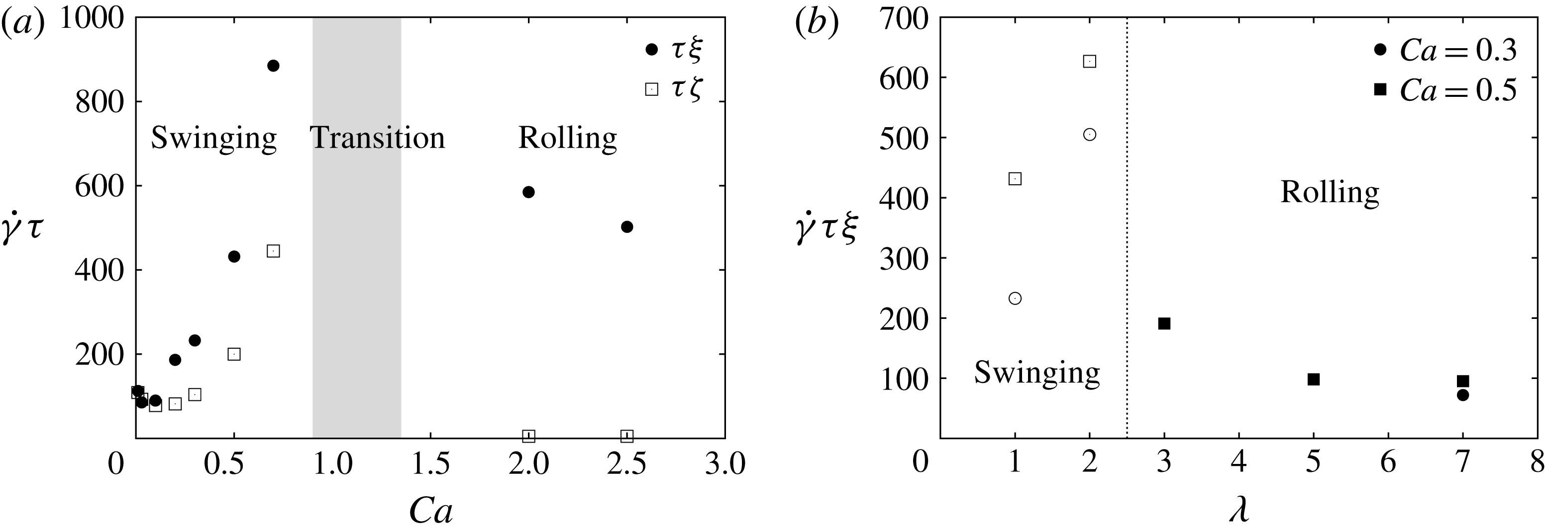
The convergence time depends significantly on whether it is based on
 ${\it\zeta}(t)$
or on
 ${\it\xi}(t)$
as is apparent in figure 11(a), where
 $\dot{{\it\gamma}}{\it\tau}$
is shown as a function of
 $Ca$
for
 ${\it\lambda}=1$
. Indeed, in the swinging regime, the convergence time
 ${\it\tau}_{{\it\xi}}$
is roughly twice
 ${\it\tau}_{{\it\zeta}}$
. We note that the convergence time increases with
 $Ca$
in the swinging regime and decreases in the rolling regime. The effect of the viscosity ratio is that it significantly increases
 ${\it\tau}_{{\it\xi}}$
in the swinging regime as one could expect, since more energy is dissipated when the viscosity ratio increases. In the rolling regime, the response time decreases when the viscosity ratio increases because the capsule is less deformed and tends to behave like a rolling axisymmetric solid body. Note that experimentally, it is
 ${\it\zeta}(t)$
which is readily measured: to obtain
 ${\it\xi}(t)$
, one would need to attach a marker to the membrane and follow its motion over time. One must also be careful experimentally when an apparent steady inclination is obtained for
 ${\it\zeta}$
: it can be misleading, since the membrane will not be at equilibrium with the fluid until
 ${\it\xi}$
has reached its final position.
5 Discussion and conclusion
The mechanical equilibrium configurations of an oblate capsule subjected to a simple shear flow have been determined numerically by initially positioning the capsule revolution axis off the shear plane and following the capsule dynamics. The study has been conducted for a capsule with a strain-hardening behaviour of the Skalak law type (Skalak et al.
Reference Skalak, Tozeren, Zarda and Chien1973) and different values of the viscosity contrast
 ${\it\lambda}$
. We have mainly considered the aspect ratio
 $a/b=1/2$
, but have compared the results with
 $a/b=2/3$
to look at the effect of changing the capsule shape. We have been very careful to make sure that the equilibrium states were time converged. We show that, to characterise the motion of the capsule unambiguously, it is necessary to monitor two angles which measure the general orientation
 ${\it\zeta}(t)$
of the deformed profile and the position
 ${\it\xi}(t)$
of the capsule initial apex.
Contrary to previous results in the literature, we find that the equilibrium motion of an oblate capsule is independent of the initial position. For example at
 ${\it\lambda}=1$
(an extensively studied case), the tumbling and swinging regimes, obtained when the capsule axis is in the shear plane, are mechanically stable equilibrium configurations at low and moderate values of
 $Ca$
(
 $Ca<0.9$
). When
 $Ca$
increases, the capsule axis migrates away from the shear plane: a wobbling precession about the vorticity axis occurs for intermediate values of
 $Ca$
until a stable rolling motion is reached, where the capsule initial apex is located on the vorticity axis (
 $Ca\geqslant 1.5$
). When the aspect ratio is increased, we find that the swinging regime is stable over a smaller range of capillary numbers: the capsule has an out-of-shear-plane motion from lower capillary numbers onwards. It is interesting to note that for a prolate capsule with
 $a/b=2$
, the stable equilibrium states at
 ${\it\lambda}=1$
occur in reverse order as
 $Ca$
increases: rolling, wobbling and swinging (Dupont et al.
Reference Dupont, Salsac and Barthès-Biesel2013).
A question that arises at this point is whether those different equilibrium states could be predicted from some simple physical considerations, such as minimisation of the system energy. The results obtained on prolate capsules showed that the stable equilibrium state does not necessarily correspond to the minimum viscous energy dissipation, except for small capillary numbers, when the capsule is subjected to small elastic deformation (Dupont et al.
Reference Dupont, Salsac and Barthès-Biesel2013): it then converges towards the rolling regime like a solid ellipsoidal particle. But for
 $Ca>0.6$
, the membrane deformation plays too large a role: the capsule converges towards configurations that no longer correspond to minima in viscous energy dissipation, the equilibrium configuration being dictated by the fluid–structure interactions. This shows that the minimum energy criterion fails to determine the equilibrium state for a deformable capsule subjected to an external flow, even under Stokes flow conditions. As a consequence, it is not possible to test the equilibrium stability by adding an initial perturbation to the energy and observing its convergence/divergence, as the dynamics depends on nonlinear fluid–structure interactions. The only possibility is thus to simulate different cases and deduce the state diagrams.
The present results agree in essence with those presented in Omori et al. (Reference Omori, Imai, Yamaguchi and Ishikawa2012) for oblate capsules in the case of low viscosity ratios: they had also found for
 ${\it\lambda}\leqslant 2$
that the capsule revolution axis exhibited a transition from an in-plane to an out-of-plane motion and that the capsule converged towards rolling at higher capillary numbers. A good agreement is found for the value of the capillary number at the wobbling-to-rolling transition considering that the aspect ratios are not exactly the same in both studies: at
 ${\it\lambda}=1$
, Omori et al. (Reference Omori, Imai, Yamaguchi and Ishikawa2012) obtained
 $Ca=1.45$
for a capsule following Skalak law (unknown value of the parameter
 $C$
) with
 $a/b=0.4$
, which compares well with our value of
 $Ca=1.2$
obtained for
 $a/b=0.5$
. Such is, however, not the case for the swinging-to-wobbling transition (0.1 versus 0.9 in our case). Would the value of the
 $C$
-parameter in the Skalak law account for such a difference?
Cordasco & Bagchi (Reference Cordasco and Bagchi2013) also found that the capsule tends towards the shear plane for
 $Ca\leqslant 0.6$
, but they observed a kayaking (i.e. an oscillation about the shear plane) or a precession-to-kayaking motion, which depended on the initial orientation. This conclusion is due to too short computational times (
 $\dot{{\it\gamma}}t\,\leqslant \,100$
). Indeed, we also find such a kayaking motion (see figure 4
b), but it is transient and dies out with time. As for Wang et al. (Reference Wang, Sui, Spelt and Wang2013), they considered only moderate values of
 $Ca$
and thus missed the rolling motion. They find different regime modes which depend on the initial orientation. This may be due to small inertial effects, as the Reynolds number is small but finite in their study, whereas it is exactly zero in our case.
The new results provide detailed information on the influence of the internal-to-external viscosity ratio on the mechanical equilibrium configurations of oblate artificial capsules. We find that, for moderate value (
 ${\it\lambda}<4$
), the internal viscosity limits the range of
 $Ca$
for which a swinging motion is possible. This can be easily understood, as high internal viscosity leads to high viscous energy dissipation during membrane rotation. In fact for large enough viscosity (
 ${\it\lambda}\geqslant 4$
), the only in-plane motion is the quasi-solid tumbling motion. The other effect of large internal viscosity is to shift to low
 $Ca$
values the transition from in-plane to rolling motion. A large internal viscosity leads to a significant tension jump across the interface and thus to membrane buckling, as reported by Foessel et al. (Reference Foessel, Walter, Salsac and Barthès-Biesel2011) and Yazdani & Bagchi (Reference Yazdani and Bagchi2013). The capsule deformability thus has a great influence on the mechanical equilibrium configuration, which depends on the fluid–structure interactions. It was finally found that, at higher viscosity ratio (
 ${\it\lambda}\geqslant 4$
), the main effect of increasing the aspect ratio is to shift the transition to rolling to a higher capillary number. The wobbling motion occurs over a larger range of capillary numbers.
Although the particle geometry is not the same, it is still of interest to compare the present results to experimental ones on RBCs. Goldsmith & Marlow (Reference Goldsmith and Marlow1972) highlighted the influence of the membrane deformability on the stable equilibrium configuration. They observed that when the RBC membrane is stiffened, the cell no longer tends towards the rolling motion but instead towards the tumbling motion. This is consistent with the present results, since stiffening the cell membrane corresponds to increasing
 $G_{s}$
and thus decreasing
 $Ca$
. In his experimental study, Bitbol (Reference Bitbol1986) varied the internal viscosity and the external shear rates. To estimate the corresponding values of viscosity ratios and capillary numbers, one can use as characteristic length for an RBC
 $\ell \sim 2.8~{\rm\mu}\text{m}$
, which corresponds to a cell volume of order
 $100~{\rm\mu}\text{m}^{3}$
(Klöppel Reference Klöppel2012). The value of shear elastic modulus
 $G_{s}$
depends on the constitutive law. Hochmuth & Waught (Reference Hochmuth and Waught1987) estimated
 $G_{s}\simeq 4~{\rm\mu}\text{N}~\text{m}^{-1}$
for a strain-hardening law, such as the Skalak law. Using these values, the results by Bitbol (Reference Bitbol1986) for low values of the viscosity ratio are that the cell exhibits tumbling up to
 $Ca=0.014$
, before drifting towards the vorticity axis in the range
 $0.014\leqslant Ca\leqslant 0.7$
. For
 $Ca>0.7$
, the cell then follows a
 $C=0$
orbit (i.e. rolling). Those results are also corroborated by Dupire et al. (Reference Dupire, Socol and Viallat2012), who have found that tumbling occurs up to approximately
 $Ca=0.05{-}0.075$
at
 ${\it\lambda}\simeq 1$
. One must note that the concept of transition is expressed in slightly different terms experimentally and numerically: concerning the tumbling-to-wobbling transition, it is clearly explained in Bitbol (Reference Bitbol1986) and Yao et al. (Reference Yao, Wen, Yan, Sun, Ka, Xie and Chien2001) that it is not as if all the cells would start precessing around the vorticity axis at a given
 $Ca$
. From the critical capillary number onwards, it is observed that more and more cells start precessing while the others continue tumbling, the ratio of the precessing cells over tumbling ones increasing when the capillary number is increased. Numerically, we find that tumbling stops for
 $Ca>0.02$
and that rolling occurs for
 $Ca>1$
, in agreement with the experimental findings when all the cells have the same motion.
Even though the experimental results on RBCs agree well with the present ones on oblate capsules, one could still wonder about the potential effect of the particle shape. The results of § 3.3 obtained by changing the aspect ratio, however, indicate that this parameter has a limited influence on the dynamics of oblate deformable capsules. An increase in aspect ratio provides the same qualitative capsule behaviour and only modifies slightly some of the capillary number values at the transitions between regimes. In the
 $Ca$
–
 ${\it\lambda}$
phase diagram, the main influence of
 $a/b$
is to increase the
 $Ca$
-range over which wobbling is stable: this effect is mostly notable when the viscosity ratio is quite larger than 1. It is thus surprising that Cordasco & Bagchi (Reference Cordasco and Bagchi2013) indicated that, at
 $Ca=0.1$
and
 ${\it\lambda}=1$
, oblate capsules tended towards an in-plane motion, whereas RBCs exhibited a rolling motion. Since their simulations were run for a finite Reynolds number, it is possible that, although small, inertia affects the dynamics of deformable ellipsoidal particles. The differences in behaviour are more likely to be accounted for by inertial effects than by membrane viscosity. The wheel-like rolling motion was indeed simulated by MacMeccan et al. (Reference MacMeccan, Clausen, Neitzel and Aidun2009) for RBCs with
 ${\it\lambda}=5$
using the lattice Boltzmann method. The simulations agree well with the experimental results of Yao et al. (Reference Yao, Wen, Yan, Sun, Ka, Xie and Chien2001), the small differences being most likely due to uncertainties in RBC material properties and in the RBC distance from the wall in the experiments. Since the numerical models did not include membrane viscosity, it can be expected that membrane viscosity does not play a central role in the wheel-like rolling motion, but that it rather adds up to the viscosity of the inner fluid (i.e. the RBC haemoglobin solution) giving rise to a global viscosity of the particle.
We have finally shown that a capsule initially placed off the shear plane takes a finite time to reach its stable equilibrium configuration depending on its initial orientation, flow strength and viscosity ratio. For a medium displacement from the shear plane (
 ${\it\zeta}(0)=45^{\circ }$
), the non-dimensional convergence time when
 ${\it\lambda}=1$
varies between 50 and 400 for
 $Ca\leqslant 0.5$
and is about 600 for
 $Ca\geqslant 2$
. Long computational times are thus required to study the equilibrium configurations of oblate microcapsules or cells. For experiments, it is interesting to translate the non-dimensional times into dimensional ones. If one considers the case of an RBC subjected to simple shear flow, one finds that the stable tumbling equilibrium regime is reached after
 ${\sim}50~\text{s}$
(from figure 4
a), stable swinging after
 ${\sim}10~\text{s}$
(figure 4
b,c) and stable rolling after
 ${\sim}2~\text{s}$
(figure 6). Since the typical experimental window time for observation is of the order of 1 minute, one must be careful to check that equilibrium conditions have indeed been reached when the measurements are recorded.
Acknowledgements
This research was funded by Ecole Polytechnique (PhD scholarship), the Conseil Régional de Picardie (MODCAP grant), by the French Ministère de la Recherche (Pilcam2 grant) and by the French Agence Nationale de la Recherche (CAPSHYDR grant ANR-11-BS09-013, Labex MS2T ANR-11-IDEX-0004-02).
Supplementary movies
Supplementary movies are available at http://dx.doi.org/10.1017/jfm.2015.759.



