I. INTRODUCTION
The properties of privacy and security in wireless communication systems have attracted increasing attention as these networks continue to flourish. Wireless networks in particular, which lack a physical boundary due to their inherent broadcast nature, face major security challenges. Recently it has been shown that physical layer security in wireless networks can assist with resolving transmission boundary issues [Reference Li, Hwu and Ratazzi1].
The phased array can be considered as a basis architecture for secure physical layer wireless systems. For a classical antenna array, its far-field pattern corresponds to the transmission boundary, and spatial selectivity obtained through high gain improves security with respect to eavesdropping. Recently techniques under the banner of directional modulation (DM) have been proposed for spatially dependent Quadrature phase-shift keying (QPSK) signal transmission [Reference Daly and Bernhard2, Reference Daly and Bernhard3]. The technique relaxes the strict requirement of narrow main lobe and low sidelobes as required in classical secure physical layer wireless communication solutions. DM is achieved by directly encoding baseband information content on antenna array structures in such a fashion to produce, on a per symbol basis, phased vector summation of array element radiation only along a pre-specified spatial direction. The consequence of this is to produce constellation diagram patterns that differ at each observation angle in the spatial domain, thus enhancing security directly at the physical layer.
Attempts to date at DM systems synthesis [Reference Daly and Bernhard2–Reference Babakhani, Rutledge and Hajimiri7], have failed to consistently produce optimal QPSK constellations in the required spatial direction while simultaneously producing grossly non-optimal constellations in all other directions. In this paper, we propose a strategy to overcome this. Furthermore, we derive the upper and lower bounds of bit error rate (BER) in a DM system, which can be used for DM optimization under different assumptions of eavesdroppers' capabilities. The effect of a key parameter, namely the extra power required by DM arrays, is also revealed in this paper.
In Section II of this paper, the structure of a phased DM array is briefly presented; this is followed by discussion of a synthesis strategy based on BER-driven optimization. This synthesis procedure guarantees that the standard QPSK modulation constellation patterns are able to be formed with the prescribed BER performance along the selected secure communication direction. This has not been achieved in the previous works [Reference Daly and Bernhard2–Reference Babakhani, Rutledge and Hajimiri7]. In Section III, we investigate the limitation of the existing performance assessment metrics for DM systems, and suggest three BER definitions that are relevant for DM QPSK systems equipped with receiver detection equipment with different decision-making functionality. Examples of DM QPSK array synthesis for secure communication based on the proposed definitions are presented and discussed in Section IV and verified by the experiment for a 1 × 4 dipole array in Section V. Conclusions are drawn in Section VI.
II. DM SYSTEM AND DESIGN PROCEDURE OF PHASED DM ARRAYS
For the purposes of this paper, DM is defined as a means for transmitting digital symbols with standard modulation mappings in In-phase and Quadrature (IQ) space along a pre-specified spatial direction, while simultaneously distorting the constellation mappings of the same digital symbols in all other directions.
The main properties of a DM QPSK wireless array operating in free space are illustrated in Fig. 1. Here, we note that since the array far-field magnitude and phase responses representing each symbol are, unlike a conventional phased array system, not identical the symbol positions in IQ space become a spatial function of observation direction. Consequently the standard formatted constellations, e.g., for QPSK (i.e., central-symmetric square as in Fig. 1), are not preserved away from the a priori defined observation direction.
Illustration of the major properties of a DM QPSK system and a typical phased DM array architecture. Along a pre-specified direction a usable constellation is formed. Away from desired direction the constellation is scrambled.

DM transmitters are currently implemented using two main architecture types. Parasitic DM transmitters [Reference Babakhani, Rutledge and Hajimiri6, Reference Babakhani, Rutledge and Hajimiri7] rely on near-field coupling effects. These are complex to design and to implement and are therefore not considered as suitable for the direct synthesis approach we propose in this paper. On the other hand, phased DM arrays [Reference Daly and Bernhard2, Reference Shi and Alan8, Reference Shi and Alan9], which follow a modification of classical phased array technology in order to achieve baseband encoding on RF stage are considered to be suitable.
A typical phased DM array architecture is also shown in Fig. 1. Prior to transmission via N antenna elements, amplitude weighted (A mn) carriers (f c) are modulated by baseband information data controlled phase shifters whose values are Phase mn, where m (m = 1, 2, …, M) and n (n = 1, 2, …, N) correspond to the mth signal symbol and the nth array element, respectively. For this architecture the mth received symbol (S m) in IQ space can be obtained by weighting each term of the array factor (AF) by the corresponding antenna patterns (APs), (1). Transmission in free space is assumed. Equation (1) describes the arrangement. Here  $\vec{k}$ is the wavenumber vector along the spatial transmission direction, and
 $\vec{d}_n$ represents the location vector of the nth array element relative to the array phase center.
 $$S_m=\sum\limits_{n=1}^{N}\left(AP_{n} \times A_{mn} \times e ^{-j\times phase_{mn}+j\times (\vec{k}\cdot \vec{d}_{n})}\right)\comma$$
Based on the DM transmitter structure in Fig. 1, a procedure for phased DM array synthesis is now described:
• Assume that the antenna pattern AP n, n,
 $\vec{k}$, and $\vec{d}_{n}$ are known, calculate using (1) the received symbols (S m) in IQ space with initial amplitude weights (A mn) and arbitrary initial phase values (Phase mn).
• Calculate the spatial BER distribution, BER cal, based on the S m values obtained in the previous step for a constant distance from the DM transmitter array. The various BER applicable calculation methods for a DM QPSK system will be discussed in Section III.
• Set the BER optimization target levels for secured and unsecured spatial directions, denoted as BER tar_se and BER tar_unse, respectively.
• Minimize the value of the cost function (V cf), (2), where W se and W unse are the weights for the secured direction and unsecured spatial region R. W unse is put inside the integral because it can be a function of φ in R; φ is the spatial direction with boresight at 90°.
(2)$$\eqalign{V_{cf}&=W_{se}\left(BER_{cal \_ se}-BER_{tar \_ se} \right)^2 \cr & \quad +\int_{R} W_{unse} \cdot \left(BER_{cal\_unse}-BER _{tar\_ unse}\right)^2 d \varphi.}$$• Recalculate S m with the optimized values of Phase mn returned from (2);
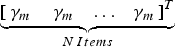
• For the desired spatial direction rotate each S m in IQ space by γ m radians clockwise in order to align its phase to that of the corresponding standard constellation point. This is achieved by adding
$\mathop{\underbrace{\lsqb \matrix{\gamma_{m} \, & \gamma_{m} & \ldots & \gamma_{m}}\rsqb ^T}}\limits_{N \, Items}$ to [Phase m1Phase m2···Phase mN]T.• For the desired spatial direction scale each S m independently in IQ space by g m in order to align its amplitude and that of the corresponding standard constellation point. This is achieved by multiplying [A m1 A m2 … A mN]T by g m. This step requires the use of variable-gain control elements. If these are not available then the initial amplitude weightings (A mn) can be set equal for each symbol transmitted. Consequently, only one attenuator or amplifier is needed before the power splitter in order to modulate the amplitude of the carrier f c during the data transmission.
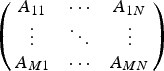
• Simultaneously scale
$\left({\matrix{ {A_{11}} & \cdots & {A_{1N}} \cr \vdots & \ddots & \vdots \cr {A_{M1}} & \cdots & {A_{MN}} \cr } } \right)$ to make BER cal_se reach BER tar_se along the required secure communication direction. This scaling coefficient can be combined with g m in the last step, thus no further hardware is required.• After obtaining the settings for Phase mn and A mn using the steps mentioned above, the effect of the measured active element patterns (AEP n) [Reference Pozar10] needs to be considered and de-embedded by adding the phase of AEP n(ξ) to Phase mn and scaling A mn by |AEP n(ξ)|−1 along the required secure communication direction ξ. This post-de-embedding step makes the DM synthesis more flexible since it removes the need for detailed knowledge of the radiating element characteristics at the initial stage of the optimization process.



The synthesis approach described above ensures that along the desired spatial direction a standard constellation mapping in IQ space is produced, an aspect not discussed nor achieved in previous literature.
III. BER CALCULATIONS FOR A DM QPSK SYSTEM
Since the value of the cost function (2) is minimized based on BER calculation, a fit for purpose BER calculation scheme now requires detailed discussion.
In [Reference Babakhani, Rutledge and Hajimiri6, Reference Babakhani, Rutledge and Hajimiri7] the authors chose ‘error rate’ as the figure of merit. Here the magnitude and phase reference of the detected constellation pattern were not defined, making it difficult to systematically assess the secrecy performance of a DM system. In particular, since channel noise and coding strategy was not considered, the ‘error rate’ metric is not able to capture the performance difference if: (a) a noiseless constellation symbol is constrained within its compartment, one quadrant for QPSK, but locates at different positions within that compartment; (b) a noiseless constellation symbol is out of its compartment but falls into a different one of other compartments. These factors suggest that the ‘error rate’ metric is not equivalent to BER and is not considered suitable for our BER-based synthesis method.
In [Reference Daly and Bernhard2–Reference Daly, Daly and Bernhard5, Reference Hong, Song and Liu11], a closed-form BER equation, (3), for QPSK modulation based on “minimum Euclidean distance decoding” was adopted. However, since BER as a performance metric is defined to a large extent by receiver functionality some further discussion is needed. Firstly, we point out that the ‘½’ before the Q function was erroneously added in previous works, and it should be removed [Reference Shafik and Rahman12, Reference Goldsmith13]; Secondly, we comment that with the extra capability of constellation pattern manipulation possessed by a DM transmitter, “minimum Euclidean distance decoding” is no longer directly applicable, this is discussed further below. Furthermore, in these systems a symbol pair with minimum distance can be a non-Gray-code pair. These observations suggest that (3) may not be the best BER figure of merit to use when considering DM systems.
 $$BER^{\prime}={1\over 4} \times \sum\nolimits^{4}_{i=1}\left[{1\over 2} \times Q\left({\sqrt{\lpar d_i/2\rpar ^2\over N_0/2}}\right)\right].$$
Next we present alternative BER equations for different receive scenarios that can occur with DM systems.
(a) Consider that a more advanced receiver is available, which can detect the absolute magnitude and phase of each received symbol. This type of receiver is denoted as APSK in this paper. Under this assumption, an error occurs when a noisy symbol crosses the boundary between each symbol pair. It is reasonable to set this boundary at the geometric center of each pair since the additive channel Gaussian noise spreads each of the received symbols to clouds of the same size. Also since the majority of errors occur between symbol pairs with minimum distance in IQ space, only four symbol pairs in a DM QPSK system need to be considered. Therefore, the BER equation associated with an APSK class receiver in a DM QPSK system can be expressed as in (4),
 $$BER_{DM \_APSK}={1\over4}\times\sum\limits_{i=1}^{4}\left[2^{k_{i}} \times Q \left({\sqrt{\lpar d_i/2\rpar ^2\over N_0/2}}\right)\right]\comma$$
where
•
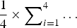
${1\over 4} \times \sum\nolimits_{i=1}^{4}\ldots$: This represents the average of the BER of four different symbols in a QPSK system;•
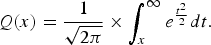
$2^{k_{i}}$, (i = 1, 2, 3, 4): k i equals 0 if two symbols with the minimum distance are a Gray code pair, i.e., where two symbols differ in only one bit, (or 1 for a non-Gray code pair). ‘2’ accommodates that a symbol for QPSK consists of two bits;• Q(x): It is the scaled complementary error function,
$Q\lpar x\rpar ={1\over{\sqrt{2\pi}}}\times \int_{x}^\infty {e^{t^{2}\over 2}}dt.$ Symbol error rate (SER) can be obtained by replacing x with $\sqrt{SNR}$;•
$\lpar d_{i}/2\rpar ^2\over N_{0}/2$: This term is the equivalent signal-noise ratio (SNR) detected by the APSK receiver in a DM QPSK system. N 0/2 is the noise power spectral density over a Gaussian channel. d i is minimum distance between the ith noiseless symbol with respect to any other noiseless symbols.



It is noted that (4) is quite similar to (3) except for the Gray code inspection. The BER detected by this APSK type receiver is the lower bound of the system BER performance along unselected communication directions.
(b) Another receiver type is the one that can detect only the absolute phase of each received symbol, denoted hereafter as PSK receiver. Here the decision boundary to judge if a received noisy symbol is decoded erroneously should be located at the angular bisector of the angle between each two symbols. Therefore, the BER equation associated with a PSK class receiver in a DM QPSK system can be expressed as in (5). Similar to the APSK receiver case, it is assumed that the majority of errors occur between symbol pairs with minimum phase interval in IQ space. In (5) parameters l i and α i (i = 1, 2, 3, 4), which are utilized to obtain the minimum projection distance, l i·sin(α i/2), are the magnitude of the ith symbol and the minimum phase interval between the ith symbol and any other symbols respectively; see Fig. 2.
 $$BER_{DM \_PSK}={1\over4}\times\sum\nolimits_{i=1}^{4}\left[2^{k_{i}} \cdot Q \left({\sqrt{l_{i}^2 \cdot \sin^2\lpar \alpha_i/2\rpar \over N_0/2}}\right)\right].$$
Illustration of l i, α i, and minimum projection distance for the PSK receiver case.
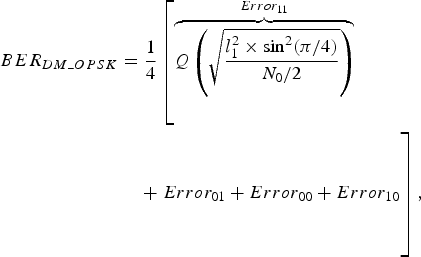
(c) The last but most realistic case is that standard QPSK receivers, which decode received symbols based on which quadrant the constellation points locate, are available. Contrary to the APSK case, BER detected by this QPSK-type receiver is the upper bound of the system BER performance along undesired communication directions. In this case prior to decoding, a phase reference needs to be obtained by carrier recovery or synchronization. For discussion below, the phase of the noiseless symbol ‘11’ is set as the reference. This means that the received constellation patterns are always rotated to align the phase of the symbol ‘11’ to π/4 in the first quadrant. Under such circumstances, BER can be calculated approximately by (6),
 $$\eqalign{BER_{DM\_OPSK}&= {1\over4}\left[\overbrace{Q\left({\sqrt{l^{2}_{1}\times \sin^{2} \lpar \pi/4\rpar \over N_{0}/2}} \right)}^{Error_{11}}\right. \cr & \left. \quad + \;Error_{01} + Error_{00}+Error_{10} \vphantom{\overbrace{Q\left({\sqrt{l^{2}_{1}\times \sin^{2} \lpar \pi/4\rpar \over N_{0}/2}} \right)}^{Error_{11}}} \right]\comma \; }$$
where the Error xy is the BER detected when the symbol ‘xy’ is transmitted ({‘11’, ‘01’, ‘00’, ‘10’}). Under our synchronization assumption, the noiseless symbol ‘11’ is always phase aligned, thus Error 11 can be calculated by 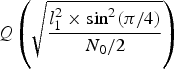 $Q\left({\sqrt{l^{2}_{1}\times \sin^{2} \lpar \pi/4\rpar \over N_{0}/2}} \right)$. For the other three symbols, the Error xy can be obtained by
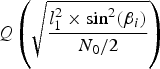 $Q\left({\sqrt{l^{2}_{1}\times \sin^{2} \lpar \beta_i\rpar \over N_{0}/2}} \right)$ (i = 2, 3, 4) when the noiseless symbol ‘xy’ is constrained within its quadrant. QPSK modulation with Gray coding is adopted. Thus the symbols ‘11’, ‘01’, ‘00’, and ‘10’ in a standard QPSK system should lie in the first to the fourth quadrants respectively. Parameter β i is the minimum angle between the symbol vector and the decoding boundary, which overlaps the IQ axes, illustrated in Fig. 3. Otherwise Error xy approximates to 0.5 or 1 depending on which quadrant this distorted noiseless symbol locates, e.g., if the noiseless symbol ‘00’ is located into the second (or the first) quadrant, where the symbol ‘01’ (or ‘11’) should be, the Error 00 is set to be 0.5 (or 1).
Illustration of Error xy and β i for the QPSK receiver case.
It is observed that in all three cases, when the four constellation points in a DM QPSK system overlay their corresponding standard QPSK symbols, (4–6) are equivalent to each other, and can be expressed as in (7), which is the equation for calculating BER in a standard QPSK modulation system with Gray coding. d is the distance between each two adjacent symbols.
 $$BER_{st\_OPSK}=Q\left({\sqrt {\lpar d/2\rpar ^2\over N_{0}/2}}\right).$$
IV. SYNTHESIS RESULTS AND DISCUSSIONS
The following results and discussions in this section are given under the following prerequisites:
• QPSK modulation scheme (M = 4) is used throughout.
• One-dimensional (1D) four isotropic antenna element array with one half wavelength spacing (AP n = 1, N = 4, and
$\vec{k}\cdot \vec{d}_{n}$ =[n − (N + 1)/2]πcos(φ)).• All array element excitation amplitudes A mn are uniform, and keep constant value for every symbol transmitted during the optimization cost function minimization process.
• The particle swarm optimization (PSO) algorithm [Reference Kennedy and Eberhart14, Reference Shi and Eberhart15] is adopted for cost function minimization. Particle number is 1000 and 5000 iterations are used. The acceleration constants associated with best particle position and best global position are set to 2. All programs were developed in MATLAB 2013a [16] with running time around 15 min under a PC with 8 GB memory for each DM array optimization and synthesis.

By following the design procedure presented in Section II, and using (4–6) for BER calculation, DM transmitter arrays operating in the broadside (90°) and 30° directions are synthesized. During the optimization, the BER tar_se and BER tar_unse are set to be 10−8 and 100, respectively. We set the noise power spectral density, N 0/2, to be (1.98)−2, meaning that a symbol magnitude of 4, resulting in a SNR of 15 dB, in a standard QPSK constellation pattern is required for BER to reach BER tar_se, 10−8, along the desired directions ξ, 90° and 30° in the examples. This normalizes the excitation magnitude of each array element to be unity in a conventional array. The weights W se and W unse associated with each BER target are set equal to 10+18 and configured as in (8), respectively. The weight of 10+18 used for W se makes the term  $W_{se}\lpar BER_{cal\_se}-BER_{tar\_se}\rpar ^2$ two orders larger than its counterparts at other unsecured directions. This is done so that BER tar_se is reached with low residual error that can then be readily eliminated by minor phase rotation and amplitude scaling afterwards, as we stated in Section II. Instead of setting a constant W unse over the whole unsecured region R, R = {φ|0° ≤ φ < ξ − 5° or ξ + 5° < φ ≤ 180°}, two spatially symmetrical transition sections with linearly varying W unse are used. These two tapered sections prevent the optimized BER beams from shifting around in space.
 $$W_{unse} = \left\{\matrix{1 \hfill 0^{\circ} \le \varphi \lt \xi - 10^{\circ} \hfill &\hbox{or}\, \;\;\;\;\;\;\xi + 10^{\circ} \lt \varphi \le 180^{\circ}\comma \; \hfill \cr 1 + {10^3 - 1\over 5^{\circ}} \cdot\lsqb \varphi - \lpar \xi - 10^{\circ}\rpar \rsqb \hfill &\lpar \xi - 10^{\circ}\rpar \le \varphi \lt \lpar \xi - 5^{\circ}\rpar \comma \; \hfill \cr 10^3 + {1 - 10^3\over 5^{\circ}} \cdot \lsqb \varphi - \lpar \xi - 5^{\circ}\rpar \rsqb \hfill &\lpar \xi + 5^{\circ}\rpar \lt \varphi \le \lpar \xi + 10^{\circ}\rpar \comma \; \hfill \cr 0 \hfill \hfill & \;\;\;\;\;\;\;\;\;\;\;\;\;\;\;\;\;\;\;\;\;\;\;\;\;\;\;\;\;\;\;\;\;\;\;\hbox{otherwise}.} \right.$$
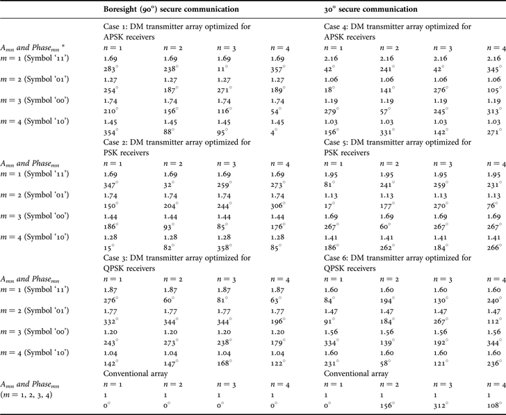
The values of phase shifters (Phase mn) and amplitude weights (A mn) needed for transmission of each QPSK symbol for each of the three different receiver configurations are listed in Table 1. During the optimization, the total power radiated by the DM array is set to be 4.5 dB higher than that of the conventional array, 10 × log10[(N ×A mnReference Daly and Bernhard2)/(N × 12)]. In most cases, the total radiated power of the synthesized DM array is lower than this value since symbol phase refinements achieved by rotating each symbol independently enable the BER tar_se being reached with less symbol power. In the examples of the synthesized DM transmitters in Table 1, the extra power associated with Case 1 to Case 6 is 3.8, 3.8, 3.6, 3.2, 3.9, and 3.8 dB, respectively. The BER spatial distributions for each synthesized 1 × 4 DM transmitter array with the corresponding receivers, as well as uniform amplitude and progressive phase 1 × 4 conventional arrays, for both 90° and 30° secure communications, are depicted in Fig. 4. The resulting BERs, regardless of the receiver functionalities, converge along the desired communication directions, whereas they spread up along other directions. It can be observed that the BER beams for the synthesized DM arrays are considerably narrower than those of the corresponding conventional arrays. Also as expected, the more sophisticated the receivers are, the wider the decodable spatial region becomes, but in all cases it remains better than the conventional arrays.
BER performance, detected by the corresponding type receivers, of the synthesized 1 × 4 DM transmitter arrays as well as the 1 × 4 conventional arrays optimized for broadside and 30° secure communications with the system settings in Table 1.
Synthesized phase shifter values and excitation magnitudes for Boresight (90°) and 30° Secure Communications.
*In the DM array, we can set Phase 11 to be 0° as reference, and offset the other phases by −283° or +77°. This leads to the constellation diagram rotated by 283° counter-clockwise or 77° clockwise.
Fig. 5 shows the normalized far-field radiation power and phase patterns of the DM transmitter array for settings as in Case 2 (Table 1) when transmitting each of the four QPSK symbols. It is noticed that a certain amount of extra energy (3.8 dB in this example) compared with that of the conventional array is launched in undesired directions. This energy is utilized to distort the symbol relationships hence the constellation patterns, and thus suppress useful information in unwanted directions.
Predicted far-field radiation power and phase patterns of the DM transmitter array with settings in Case 2 Table 1 for each of the four QPSK symbols.
It is also worth mentioning that along the desired direction (boresight in this example), unlike the results obtained in the previous literature [Reference Daly and Bernhard2–Reference Shi and Alan9], the phase intervals between each two consecutive symbols produced by the DM array synthesis proposed here are exactly 90°, and the magnitudes for four symbols are identical, which indicate the formation of a standard QPSK constellation pattern. The similar results can be observed from the far-field patterns of the DM transmitter arrays in Cases 1 and 3–6 in Table 1. For brevity these patterns are omitted.
To highlight the necessity of discussing BER performance for different receiver types, consider Fig. 6. Here we compare the BER performance of the synthesized DM transmitter array with the settings in Case 2 (Table 1) but with three different type receivers. It is noted that the BER performance for APSK and QPSK receivers in Fig. 6 are worse than their counterparts in Fig. 4 with regard to the beamwidth and sidelobe levels. This is because they are not optimized for these two cases. Also a large discrepancy of BER values for the three type receivers can be observed at the direction around 58°. The constellation diagram, which can be read from the far-field patterns in Fig. 5, along this spatial direction is also illustrated in Fig. 6. To facilitate interpretation, this constellation diagram has been rotated to align the phase of the noiseless symbol ‘11’ to π/4 in IQ space. The symbol ‘01’ that should reside in the second quadrant is distorted to locate at the fourth quadrant, which contributes 0.25 to the total BER when a QPSK receiver is equipped. Similarly after summing up the errors induced by other symbols, the BER DM_QPSK approximates to 0.5, around 0.125 for both symbols ‘00’ and ‘10’. For the case of the PSK receiver, since the magnitude of symbol ‘10’ and the phase interval between symbols ‘10’ and ‘01’ are quite small, which result in short minimum projection distances for these two symbols, the BER DM_PSK maintains at a high level. On the contrary, in terms of the case of the APSK receiver, the BER DM_APSK is reasonably low, 10−4, since the four symbols are spread up in IQ space. Similarly a secondary dip of the BER detected by APSK receivers can also be observed if the DM transmitter array in Case 3 (Table 1) is adopted. On the other hand, the DM transmitter array in Case 1 (Table 1), which is optimized for the most sophisticated receiver type, APSK, is able to suppress BER sidelobes for each receiver types. The similar phenomenon can be observed for 30° secure communication, i.e., Cases 4–6 in Table 1. For brevity all these graphs are omitted.
BER performance, detected by each of the three different type receivers, for the synthesized DM transmitter array with the settings in Case 2 Table 1, compared with that of the conventional array.
Throughout the optimization, no matter what receiver type we choose, the extra power a DM transmitter utilizes as compared with the conventional array with uniform excitation amplitude and progressive phases plays a key role in determining the achievable BER performance. In Fig. 7, the BER performance detected by QPSK receivers of four synthesized DM transmitter arrays for 30° secure communication, all optimized for QPSK-type receiver, as well as that of the conventional array, is shown. During the optimization, the total radiated power for each DM array is set to be 0.5, 3, 4.5, and 6 dB more than that of the conventional array, which results in the extra power of 0.36, 2.31, 3.85, and 5.6 dB for each synthesized DM array. As expected, secured beamwidth reduction occurs at the price of the DM system power efficiency. When the extra power is close to 0 dB, the synthesized DM array is inevitably convergent to the conventional array.
BER performance, detected by QPSK receivers, of four synthesized DM transmitter arrays optimized for QPSK-type receiver but with different extra power, compared with that of the conventional array.
To illustrate the trend of BER beamwidth while scanning the selected spatial communication direction, we take the PSK receiver case as an example, the further the secure communication direction is steered away from boresight (90°) and the less extra energy fired in undesired directions, the more the beam segment for 10−6 BER widens, Fig. 8. It is also observed that the more BER beamwidth reduction can be achieved at the low azimuth angle as we increase the extra radiated power in DM arrays. The same trends can be obtained for the other receiver types.
BER 10−6 beamwidths, detected by PSK-type receiver, versus desired spatial observation angle for synthesized 1 × 4 DM transmitter arrays optimized for PSK-type receiver with different extra power consumed (the extra power (dB) is labeled beside each point), compared with that of conventional arrays.
V. EXPERIMENTAL RESULTS
To validate the synthesis results obtained in the last section and to demonstrate the post-de-embedding process mentioned at the end of Section II, a 1D four-dipole array with one-half wavelength spacing for 1 GHz operation was built and is shown in Fig. 9. The AEP n for each dipole was measured in an anechoic chamber using the procedure in [Reference Pozar10].
Fabricated 1D four-dipole array with one half-wavelength spacing for 1 GHz operation.
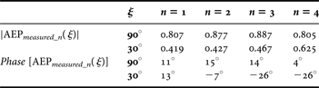
To de-embed the influence that the non-identical AEPs of four dipoles have along a prescribed communication direction ξ, the magnitude and phase values at these selected spatial angles ξ, e.g., 90° and 30°, read from Fig. 10, are listed in Table 2.
Measured AEP n (n = 1, 2, 3, 4) for each dipole.
The normalized magnitude and phase values of AEPs for each dipole at the directions of 90° and 30°.
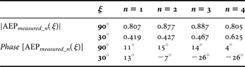
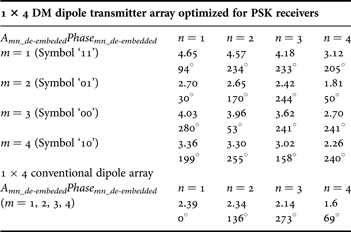
Taking the PSK receiver case for 30° secure communication as an example, Case 5 in Table 1, the de-embedded Phase m1_de-embedded is calculated by adding phase[AEP 1(ξ)], 13° shown in Table 2, to each Phase m1 (m = 1, 2, 3, 4). The other values of Phase mn_de-embedded (n = 2, 3, 4) are obtained similarly. The excitation magnitudes of each dipole also need to be calibrated by dividing A mn by |AEP n(ξ)| accordingly. The final excitation magnitudes and phase shifter values of the dipole array for 30° secure communication with PSK-type receivers are obtained and presented in Table 3.
BER performance, detected by the corresponding type receivers, of the 1 × 4 DM dipole transmitter arrays as well as the 1 × 4 conventional dipole arrays for broadside (90°) and 30° secure communications.
De-embedded excitation magnitudes and phase shifter values of the DM dipole array for 30° secure communication with PSK-type receiver.
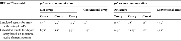
Based on the de-embedded system settings and (4)–(6), the BER performance of each 1 × 4 dipole arrays, configured as DM transmitters for different type receivers or conventional transmitters, for 90° and 30° secure communications was calculated and shown in Fig. 11. It is observed from Fig. 11 that BER curves based on the measured AEPs for the conventional and DM dipole arrays resemble those calculated using ideal isotropic element patterns, i.e., those presented in Fig. 4. The BER beam for the 30° communication case of the conventional dipole array is offset to 41° due to the power beam pointing error [Reference Toh, Fusco and Buchanan17] induced by the rapid AEP roll-off within the spatial range between 30° to 60°, shown in Fig. 10(a). This rapid roll-off also causes a secondary dip at around 60° when the APSK receivers are equipped. A summary of the advantage of the synthesized DM arrays, i.e., Cases 1–6 in Table 1, over the conventional arrays, with regards to BER 10−6 beamwidths, is presented in Table 4.
Summary of the BER 10−6 beamwidths in the synthesized DM arrays and the conventional arrays.
VI. CONCLUSION
We have discussed and suggested BER calculation metrics suitable for DM QPSK system optimization. Based on these metrics a synthesis procedure for DM arrays operating in free space was presented. It was shown for the first time how optimal constellation mappings in IQ space to a pre-specified BER can be exactly achieved along a given specified spatial direction. The BER performance of the synthesis DM arrays with different system configurations and settings, including three types of receivers and different amount of extra power consumed, was compared. Examples of DM QPSK systems for secure communication were shown to produce narrower information beamwidths than those of a conventional phased array. Such systems could add an additional physical layer of security to future mobile wireless systems.
ACKNOWLEDGEMENTS
The authors thank Dr. Yunhua Zhang for useful discussions and Mr. Michael Major for the fabrication of the 1 × 4 dipole array. This work was sponsored by the Queen's University of Belfast High Frequency Research Scholarship.
 Yuan Ding received his Bachelor's degree from the Beihang University (BUAA), Beijing, China, in 2004 and received his Master's degree from Tsinghua University, Beijing, China, in 2007, both in Electronic Engineering. He was an RF engineer in Motorola R&D center (Beijing, China) from 2007 to 2009, before joining Freescale semiconductor Inc. (Beijing, China) as a RF field application engineer, responsible for high power base-station amplifier design, from 2009 to 2011. He is currently working toward his Ph.D. degree at ECIT institute, Queen's University of Belfast, Belfast, U.K. His research interests are in antenna array and physical layer security.
 Vincent F. Fusco holds a personal chair in High Frequency Electronic Engineering at Queens University of Belfast. His research interests include active antenna and front-end MMIC techniques. He is head of the High Frequency Laboratories at QUB where he is also director of the International Centre for System on Chip for Advanced Microwireless. Professor Fusco has published over 350 scientific papers in major journals and in referred international conferences. He has authored two text books, holds patents related to self-tracking antennas and has contributed invited papers and book chapters. He serves on the technical program committee for various international conferences including the European Microwave Conference. He is a Fellow of both the Institution of Engineering and Technology and the Institute of Electrical and Electronic Engineers. In addition, he is a Fellow of the Royal Academy of Engineers and a member of the Royal Irish Academy. In 2012 he was awarded the IET Senior Achievement Award the Mountbatten Medal.