Introduction
In recent years, with the advancement of modern wireless communication, the demand for compact, low-profile multi-band antennas with better radiation characteristics has been increasing extensively. The cavity-backed antennas have fascinated researchers for a long decade with their high efficiency, gain, and unidirectional radiation characteristics. However, due to the use of the backed cavity, the overall thickness of the antenna becomes significantly higher which leads to a non-planar structure. In recent times, the substrate integrated waveguide (SIW) evolved as a promising technology to develop microwave passive components [Reference Kumar and Althuwayb1]. It has capability to offer waveguide like features such as high-quality factor and better power handling capability in a planar laminate. The SIW cavity adds the advantage of a simple printed circuit board (PCB) cost-efficient manufacturing process [Reference Luo, Hu, Dong and Sun2, Reference Chaturvedi3].
As wireless technology has been becoming prominent, the need of multi-channels for the transceivers is conspicuous [Reference Deckmyn, Agneessens, Reniers, Smolders, Cauwe, Ginste and Rogier4]. The transceivers on the same board suffer from the problem of poor isolation from the adjacent one [Reference Hao and Paini5]. The self-diplexing/triplexing antennas are in trends since they avoid the need for filtering feeding network, hence due to this reason the complexity of the overall system reduces significantly. The peculiar arrangement of the slots and the feed maintain good isolation in a compact and low-profile structure. In literature, the self-diplexing/triplexing SIW cavity-backed antennas are investigated to satisfy the requirement where multiple slots are excited by individual feedlines with maintaining adequate intrinsic isolation among the ports [Reference Hao and Paini5–Reference Kumar and Raghavan20]. The individual excitation of slots avoids the need for decoupling elements in the feeding network which makes the overall structure compact and simple. In [Reference Chaturvedi, Kumar and Raghavan6], a dual-polarized antenna is developed with enhanced isolation using a nested cavity-type arrangement. The self-diplexing antennas are developed by using a half-mode SIW resonator with an open-ended rectangular slot in [Reference Kumar, Chaturvedi and Raghavan7–Reference Kumar, Chaturvedi and Raghavan9]. The above-mentioned antenna provides average intrinsic isolation of 20 dB with dual frequency bands. However, in today's scenario with the demands of multi-channel communication, the need for transceivers more than dual frequency bands is increasing every day. To enhance the number of channels, a self-triplexing antenna is realized on a double-layered structure in [Reference Cheong, Chang, Choi and Tam10], where better isolation is maintained among the adjacent elements by using BPF. In [Reference Kumar and Dwari11], a self-triplexing antenna is realized by exciting two bowtie slots using three feeds, provides average isolation of 22 dB with a relatively larger size. The antenna developed in [Reference Arvind and Singaravelu12] offers a relatively compact structure but a poor co-cross polarization ratio. In [Reference Chaturvedi, Kumar and Raghavan13], two transverse slots and one annular rectangular slot are involved. The antenna geometry provides better isolation characteristics and a co-cross polarization ratio but relatively larger size. In order to achieve a compact structure, self-triplexing property is realized on a half-mode SIW cavity in [Reference Priya and Dwari14]. The antenna offers compactness with poor isolation characteristics. The antenna developed in [Reference Dash, Cheng, Barik, Pradhan and Subramanian15] offers better isolation but relatively poorer bandwidth. The above antennas are viable in terms of frequency tuning with different types of radiating slots and their combinations. However, the proposed antenna offers much simple and compact structure than any other existing self-triplexing antenna. Furthermore, many designs with good in-band performance were presented in [Reference Priya, Dwari, Kumar and Mandal16–Reference Kumar, Chaturvedi, Saravanakumar and Raghavan21].
In this paper, a novel technique for additional frequency band generation using metallic strips is projected. The proposed antenna is compact in size, provides triple frequency-band communication at 4.85, 5.87, and 7.3 GHz, respectively. Initially, a self-diplexing antenna is realized by etching a non-resonant V-shaped slot on the half-mode SIW cavity. Later, a self-triplexing antenna is designed by joining two EM-cavity sections. In self-diplexing configuration, the slot divides the half-mode cavity into two eight mode cavity sections and one quarter-mode (QM) cavity. The antenna yields dual-frequency bands, when one EM cavity and a QM cavity is fed with an individual microstrip feed line. On the other side, when the metallic strips are inserted to join the two EMSIW cavity sections, the antenna yield one more resonance due to the excitation of TE120 mode. Therefore, the triple frequency bands are achieved by inserting metallic strips in a V-shaped-slot dual-fed antenna configuration. The proposed geometry has the viability to use dual or triple frequency bands as per requirement. The organization of the paper is summarized as follows. First, a dual-frequency antenna is designed and investigated thoroughly. Second, a triple frequency band antenna is designed and optimized. In the next section, the experimental results of the fabricated prototype have been discussed and compared with the simulated results. The comparison of the proposed antenna with the other prevailing antennas is illustrated in the last section.
Design and principle of operation
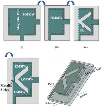
The proposed HMSIW cavity-backed slot antenna configuration is exhibited in Fig. 1. The design evolution topology from the full-mode cavity to the miniaturized proposed antenna has been demonstrated in Fig. 2. All the simulations to arrive at an optimized geometry are carried out using CST 2018 Electromagnetic Simulator. Initially, the dimensions of the full mode square SIW cavity is evaluated from (1) illustrated below [Reference Kumar19].

for QMSIW cavity

for EMSIW cavity

W eff and L eff are the effective width and length and of the cavity where W eff = W c − (d 2/0.95s), L eff = L c − (d 2/0.95s),

where ɛreff is the effective dielectric constant, ɛr is the dielectric constant of the material, wf is the trace thickness, d is the diameter and s is the spacing between vias, W c, L c are the physical width and length of the cavity. The sidewalls of the square SIW cavity are formed by embedding the shorting vias to connect the top and bottom metallic claddings. The cavity is fed with two 50 Ω microstrip feed lines into two orthogonal planes, shown in Fig. 2(a). The TE110 mode of the FMSIW cavity resonates at 5.3 GHz. Due to the symmetrical nature of the dominant mode, a half-mode cavity is realized by bisecting it along one of the magnetic walls, shown in Fig. 2(b).
Schematic diagram of proposed design, Dimensions (W = 25, L = 36, Lc = 26, Wc = 13.5, lc1 = 11, lc2 = 10, lslot = 14.5, wslot = 4, g = 0.85, d = 1, s = 2, wf1 = 2.4, wf2 = 4.8,) (Units: mm).

Construction of proposed triple-band antenna: (a) FMSIW cavity (b) HMSIW cavity (c) combination of hybrid cavity resonators (2EMSIW + QMSIW) (d) proposed antenna geometry (e) perspective view of the proposed antenna.

The half-TE110 mode shifts toward the lower frequency side and resonates at 5 GHz. This downward shift is obtained due to an increment in the fringing field from the open side of the cavity. To achieve a self-diplexing antenna property, a non-resonant V-shaped slot of one side length (lslot) 0.65λg is etched on the top wall of the HMSIW cavity. The slot divides the HMSIW cavity into two EMSIWs and one QMSIW cavity. This arrangement of hybrid cavity resonators yields two distinct resonances at 4.85 and 5.87 GHz, respectively when one EMSIW and QMSIW fed with separate microstrip feedlines. Both the cavities predominantly radiate through the V-shaped slot due to the modified TE110 modes of their respective cavities. The dimensions of the QM/EM cavities can be evaluated from (2) & (3) [Reference Deckmyn, Agneessens, Reniers, Smolders, Cauwe, Ginste and Rogier4]. The leakage of power from one port to another port is minimal due to the orthogonal polarization of the field from both cavities. The isolation is maintained up to 32 dB that is better than almost any of the existing antennas in the literature [Reference Chaturvedi, Kumar and Raghavan6–Reference Priya and Dwari14]. The return loss can be improved easily by altering the feed-line dimensions i.e. lc, wf1 and wf2.
Results and discussions
The proposed triple-frequency band antenna is formed by joining the two EMSIW cavity sections with the help of two metallic strips. The proposed antenna produces three distinct resonances at 4.85 GHz, 7.3 GHz due to Cav1′ and at 5.85 GHz due to Cav2. The overall footprint of the proposed antenna is 0.57λ 1 × 0.8λ 1 mm2. The design steps and parametric analysis are explained in a more detailed way in the preceding sections.
Self-Diplexing antenna
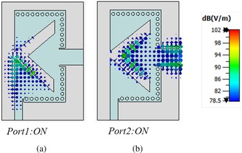
Without metallic strips, the Cav1 is an original EMSIW cavity. To achieve a compact size self-diplexing antenna, TE110 mode is selected as an operating mode for both cavities. EMSIW cavity is fed with half of the width of the 50Ω characteristic impedance line to match with the cavity input impedance. Thus, the feed width is optimized to cancel the imaginary impedance and to achieve better impedance matching. Port decoupling is accomplished better than 30 dB due to orthogonal polarization of the fields as well as the large width (w slot)of the slot. The electric field distributions in both the cavities are displayed in Fig. 3. When Port1 is ON, the field primarily radiates through the slot and some portion from the open sidewall. On the other hand, when Port2 is ON, the total field radiates through the slot with maintaining a good decoupling with the other port. The distinct resonances appear at 4.85 and 5.87 GHz due to unequal perturbation of the fields by the slot, shown in Fig. 4. The length of the slot plays a key role in improving the isolation as well as tuning both the resonant frequencies. As the length of the slot increases, both the frequency bands shift downward due to an increment in the length of the cavities.
Electric field vector at top metallic plane: (a) TE110 mode at 4.85 GHz (Port1: ON) (b) TE110 mode at 5.87 GHz (Port2: ON).

Simulated S-parameters of the self-diplexing antenna.

Also, the isolation between ports is getting improved substantially due to a decrease in the aperture that enhances the coupling between the corner sides of the cavities, the same can be observed from Fig. 5. Besides the slot length, both the resonances further can be tuned in the desired frequency range by varying the cavity lengths. It can be observed from Fig. 6(a), when the length of the cavity lc1 increases in the range of 11–12.5 mm, the resonant frequency correspondingly decreases from 5.3 to 4.8 GHz. Similar behavior can be observed in Fig. 6(b), as the lc2 increases in the range of 9.5–11 mm, the corresponding resonant frequency decreases 6.25–5.8 GHz. Hence, it can be concluded that both resonances have great flexibility of tuning along with maintaining a better decoupling between the ports.
Simulated S-parameters vs frequency with different lengths of the slot.

Simulated S-parameters with different cavity lengths (a) S 11 vs frequency for various lc1 and (b) S 22 vs frequency for various lc2.

Proposed geometry: self-diplexing antenna with metallic strips
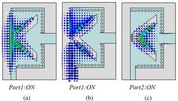
The triple-band antenna is realized by inserting two metallic strips that join the EMSIW cavities to form Cav1′. Thus, three resonating sections are combined to arrive at a miniaturized antenna. With the effect of insertion of the strips, the boundary conditions for the existence of TE120 mode get satisfied and the corresponding resonance appears at 7.34 GHz. However, the TE110 mode of the original EMSIW cavity (Cav1) does not get disturbed from its position because the EMSIW cavities consist of symmetrical field distribution. The S-parameters after introducing the strips in the self-diplexing antenna have been exhibited in Fig. 7. From the S 21 plot, it can be observed that the port decoupling does not get disturbed with the inclusion of the strips. The vector electric field distribution for each resonance frequency is displayed in Fig. 8. The first resonance with Port1 excitation displays the field distribution in the same phase in both EMSIW cavities, confirms TE110 mode existence. Also, another resonance due to Port1 excitation shows equal and opposite phase in the combination of EMSIW cavities confirms the TE120 mode. The resonance with Port2 excitation confirms TE110 in the QMSIW cavity. It can be observed from the simulated reflection coefficient plot that after introducing the strips, the bandwidth of first resonance (i.e. Cav1′) is getting decreased than the TE110 mode of the Cav1 [Reference Priya, Dwari, Kumar and Mandal16, Reference Kumar and Raghavan17]. Without the strips, the whole energy is confined in one TE110 mode. However, after inserting the strips the same energy is distributed between two modes i.e. TE110 and TE120. Thus, both the modes become mutually dependent on each other. An additional strip is introduced with the main strip for better impedance matching at both the resonances, which can be observed in Fig. 9. As the gap between the two strips increases, the first resonance shifts downward while the third resonance shifts upward. For the first resonance, the TE110 mode is maximally concentrated at the center of the strips. While the third resonance belongs to TE120 mode consists of a minimum field at the center of strips.
Simulated S-parameters of the self-diplexing antenna without strips.

Electric field vector at dielectric surface: (a) TE110 mode at 4.85 GHz (Port1: ON) (b) TE120 mode at 7.3 GHz (Port1: ON) TE110 mode at 5.85 GHz (Port2: ON).

S-parameters vs frequency for different gap between the strips.

Thus, when the gap g increasing, the effective width of the radiating strips also increasing, which leads to a decrease in the resonant frequency for the first mode. For the TE120 mode, the impedance matching is getting improved, and frequency shifts upward because of a decrease in the series capacitance [Reference Kumar and Raghavan17]. Also, the intrinsic isolation between the ports improves with g parameter. From the parametric variation, it can be observed that the antenna design is flexible in terms of tuning frequencies (i.e. f1, f2, f3) with respect to parameters (ls, lc1, lc2, and g). The optimized dimensions after parametric variations are displayed in the caption of Fig. 1.
Design Guidelines:
• A square SIW cavity of size 0.57λ 1 × 0.8λ 1 mm2 is designed using (1)
• To obtain the miniaturization, a half–mode SIW cavity is realized by bisecting the full-mode cavity along one of the magnetic walls.
• A non-resonant V-shaped slot is etched on the top-plane of HMSIW cavity to accomplish two EM and QM SIW cavity sections.
• The dimensions of the EMSIW and QMSIW cavities are determined from (2) & (3).
• A self-diplexing property is accomplished by individually exciting one EMSIW and QMSIW cavity sections.
• Two strips are inserted to yield one additional resonance due to the TE120 mode of the Cav1′.
• The resonances can be tuned in a range of frequencies by varying the lslot, lc1, lc2.
Experimental validation
A prototype of the proposed geometry is fabricated using a Rogers 5880 substrate laminate of thickness 1.57 mm and loss-tangent 0.0009.
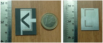
The proposed triple-band antenna is experimentally verified in terms of S-parameters, gain, and 2D-radiation patterns. The measurements are performed using MS46122B Vector Network Analyzer. The fabricated prototype of the proposed antenna configuration is depicted in Fig. 10. When Port1is excited, the antenna produces simulated frequency resonances at 4.85 and 7.35 GHz. On the other hand, when Port2 is excited, the antenna shows resonance at 5.85 GHz.
Fabricated prototype of the proposed antenna geometry.

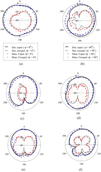
The antenna shows the measured results at 4.75 and 7.27 GHz when Port1 is fed and Port2 is terminated with the matched load. Similarly, it produces resonance at 5.9 GHz when Port2 is fed and Port1 is terminated with the matched load, shown in Fig. 11. The antenna produces the simulated values of gain 3.5, 5.5, and 6.2 dBi and measured values of gain 3.3, 5.6, and 5.9 dBi at 4.75, 5.9, and 7.27 GHz, respectively. There is a minor discrepancy is observed in the simulated and measured values of gains due to the insertion loss of the connectors and cables. The normalized radiation characteristic of the antenna is measured at two principle cut planes at (ϕ = 0°) and (ϕ = 90°) and plotted in Fig. 12 at each resonant frequency. The overall front-to-back ratio is better than 15 dB for E-plane (ϕ = 0°) and around 10 dB for H-plane (ϕ = 90°). The cross-polar levels are at least 20 dB lower than the co-polar level at each resonant frequency, specifically in the boresight direction. To show the best part of the design, the performance of the proposed triple-band dual-fed antenna is compared with other reported works [Reference Cheong, Chang, Choi and Tam10–Reference Dash, Cheng, Barik, Pradhan and Subramanian15, Reference Kumar and Raghavan20, Reference Kumar, Chaturvedi, Saravanakumar and Raghavan21] in Table 1. It can be observed that the proposed solution is more compact with moderate values of gain and a uniform radiation pattern. The proposed antenna is viable to use for dual/triple frequency band operations depending upon the usage of metallic strips. Moreover, the proposed antenna can be scaled in the desired frequency band by varying the dimensions of the cavities and slot.
Simulated and measured S-parameters, gain vs frequency.

Simulated and measured radiation patterns for E-plane (ϕ = 0°) and H-plane (ϕ = 90°) (a), (b) at 4.75 GHz (c), (d) at 5.9 GHz, and (e), (f) at 7.27 GHz.

Comparison of proposed work with the other existing works

*λ 1 is the guiding wavelength at first resonance frequency, N.A.* (not available).
Conclusion
This article presents a compact, low profile SIW cavity-backed slot antenna for dual/triple band operations depending on the usage of metallic strips. The antenna is novel in the operation as with the incorporation of metallic strips, an additional resonance starts appearing at 7.35 GHz without disturbing the resonances of the original EM and QM cavities of the self-diplexing antenna. The antenna structure radiates through a V-shaped slot with better intrinsic isolation between the ports than any other existing self-triplexing antenna developed in recent times. The experimental results validate a good matching with simulation counterparts. Moreover, the proposed design offers the advantages of the low-profile slot antenna and the planar cavity to attain moderate gain, unidirectional radiation performance in a highly compact size. The presented geometry shows better isolation and more compacted size than any other work available in the literature. In future work, a diode can be used as a switch in the place of metallic strips to enhance flexibility in the electrically tuning of the circuit.
Acknowledgements
This work was funded by the Deanship of Scientific Research at Jouf University under grant No (DSR-2021-02-0388)
 Ayman A. Althuwayb received the B. Sc. degree (Hons.) in electrical engineering (electronics and communications) from Jouf University, Saudi Arabia, the M.Sc. degree in electrical engineering from California State University, Fullerton, CA, USA, in 2015, and the PhD degree in electrical engineering from Southern Methodist University, Dallas, TX, USA, in 2018. He is currently an assistant professor with the department of electrical engineering at Jouf University, Kingdom of Saudi Arabia. His current research interests include antenna design and propagation, microwaves and millimeter waves, wireless power transfer, ultrawideband and multiband antennas, filters and other.
 Divya Chaturvedi received B.Tech. degree in electronics and communication engineering from Uttar Pradesh Technical University, India and M. Tech. in electronics engineering from Pondicherry Central University, India. She completed her doctorate degree in the Department of Electronics and Communication Engineering, National Institute of Technology Trichy (NIT-T) in 2019. Currently, she is an assistant professor in SRM University AP, India.