Introduction
In recent years, modern wearable devices such as smartwatches have gained attention because of their critical as well as attractive functions such as health monitoring, activity tracking and navigation, etc. The smartwatches communicate data wirelessly with other devices at the Wi-Fi and GPS bands [Reference Hall and Hao1]. To fulfil the increasing market demand for multi-functional and efficient antennas in smartwatches, various designs have been proposed for GPS and Wi-Fi applications [Reference Chen, Lin and Hsu2–Reference Wen, Hao, Wang and Zhou6]. The literature on on-body communications has revealed that the performance of body-worn antennas is severely affected by the properties of human tissues [Reference Werner and Jiang7]. Even though a high impedance surface was introduced in [Reference Jensen and Wallace8], the channel fading still occurs due to scattering and shadowing caused by body movements. For this reason, multiple-input-multiple-output (MIMO) technology is imperative for smartwatch applications, considering the advantages of enhanced data rate and mitigated channel path loss [Reference Chen and Ku9]. Compared with smartphones and USB dongles, smartwatches are much smaller in geometric size and closely spaced antennas are strongly coupled with each other. In addition, hand effects pose a serious design challenge to high-performance smartwatch MIMO antennas. A few designs were proposed for smartwatch MIMO antennas in literature [Reference Wen, Hao and Wang10–Reference Woo, Baek, Park, Kim and Choi14]. For instance, the theory of characteristic modes was employed in [Reference Wen, Hao and Wang10] to excite degenerate modes using orthogonally placed T-shaped monopoles and modified ground plane to achieve high port-to-port isolation over a wide frequency range. However, the geometry lacks the coplanar design requirement. The study in [Reference Wang and Yan11] demonstrated that the annular integrated ring of the smartwatch was excited by two ports to achieve polarization diversity. A dual-port antenna with wideband isolation was proposed in [Reference Li, Zhou, Zhang and You12], unfortunately, the complexity of the feed structure is not suitable for smartwatch applications. PIFA element-based MIMO antennas proposed in [Reference Chen, Yang and Sin13, Reference Woo, Baek, Park, Kim and Choi14] achieved isolation without any isolator. However, the location of the antennas is restricted and somehow impractical for modern smartwatches due to large-sized antennas. MIMO antenna elements can be embedded in the wristband of the smartwatch [Reference Govindan, Palaniswamy, Kanagasabai, Thipparaju, Alsath, Kumar, Velan, Marey and Aggarwal15]. Therefore, MIMO antennas with compact geometry, simple integration, easy fabrication, as well as wideband and high isolation properties are immensely preferred in practical scenarios.
Among numerous types of electrically small antennas available for mobile devices, a loop-type ground radiation antenna (GradiAnt) is a good choice owing to its compact geometry and good performance [Reference Cho, Choi and Kim16–Reference Liu, Kim and Kim18]. Efficient radiation of GradiAnt is attributed to its stronger coupling with the dominant ground mode [Reference Zahid and Kim19, Reference Zahid and Kim20], and this fact is closely associated with the theory of characteristic ground modes [Reference Garbacz and Turpin21, Reference Harrington and Mautz22]. The theory has been utilized in the design of high-efficiency antennas in various articles [Reference Marta, Eva, Daviu, Nogueira and Bataller23–Reference Liu, Yu, Chao, Zhang and Liu25]. Although various GradiAnt-based MIMO antennas have been studied for mobile applications [Reference Qu, Zhang and Kim26–Reference Qu, Piao, Qu, Kim and Kim28], the designs suffer from narrowband isolation or a large footprint, which cannot fit the smartwatch scenarios.
In this endeavor, compact MIMO antennas with a novel wideband isolation technique have been proposed for smartwatch applications. The technique has been demonstrated using two GradiAnt elements embedded in the periphery of the circular ground plane. An isolator consisting of a loop-type structure with a lumped capacitor is attached externally to the ground plane. Wideband isolation has been achieved by appropriate placement of the isolator and its coupling with the bezel of the smartwatch surrounding the geometry. Furthermore, the isolation property can be easily tuned using the capacitor. The proposed technique is not restricted to a specific angular displacement between the antenna elements on the ground plane. Both simulation and measurement were conducted to confirm the proposed technique is a good candidate for smartwatch MIMO applications.
Antenna geometry
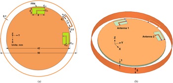
The configuration of the proposed MIMO antenna for smartwatch applications is shown in Fig 1. FR-4 dielectric (ɛr = 4.4, tan (δ) = 0.02) with a thickness of 1 mm has been used as a substrate. The ground plane is circular with a diameter of 42 mm and surrounded by a floating metallic bezel with diameter and height 50 and 5 mm, respectively. The GradiAnt elements have been installed orthogonal to each other, i.e. at the top and right edges of the ground plane. Each antenna element has been designed by etching an 8 × 4 mm2 sized clearance in the ground plane where the radiating loop contains the resonance capacitor (Cr) that is used to tune the operating frequency. Increasing the value of Cr lowers the operating frequency of the antenna. The feed loop with a size of 5 × 2.5 mm2 contains the feed capacitor (Cf) that controls the impedance matching. Increasing the Cf to an optimum value improves the matching; however, further increase degrades the matching performance. Since the loop antenna is a conventional antenna, loop-type antenna and more details of the capacitors have been discussed in [Reference Liu, Kim and Kim18]. The size of the loop-type isolator is 7.3 × 3 mm2 that contains the isolation capacitor (Cc) to control the isolation frequency. The gap (g) between the capacitor-loaded loop-type isolator and the bezel is 1 mm. Although the isolator can be placed anywhere between the antennas to achieve good isolation within the Wi-Fi band, the optimized location of the isolator is disposed closer to antenna 2, in order to achieve wideband isolation. In the proposed design, the arc distance between the shorted arm of the isolator and antenna 2 is 2.5 mm. Note that the antenna design without the loop-type isolator is designated as the reference design for comparison. There are two main factors of the isolator that provide wideband isolation: (1) location between the antenna elements and (2) coupling with the surrounding bezel. In order to explain the operation mechanism as well as the optimum location of the isolator, the characteristic modes of the geometry have been analyzed in the next section.
Proposed antenna geometry (a) front view (b) perspective view.

Antenna operation mechanism
The proposed MIMO antennas can be represented as a three-port network with the isolator port terminated at a reactive load ZL. The reflection coefficient Γ at the isolator terminal is defined as

where ZL is the capacitive load and Zo is the characteristic impedance. The network can be modeled as a 3 × 3 S-matrix. According to the decoupling theorem [Reference Qu, Zhang and Kim26, Reference Pozar29], the coupling between the antenna elements in the presence of the isolator can be expressed as,

where S’12 and S 12 represent coupling coefficients between the antenna elements with and without the loop-type isolator, respectively. In equation (2), S 13 represents the mutual coupling between antenna 1 (port 1) and the isolator (port 3), and S 23 represents the mutual coupling between antenna 2 (port 2) and the isolator (port 3). Equation (2) suggests that in order to achieve wideband isolation, the coupling between the isolator and the conducting structure is of paramount importance. In the proposed case the coupling between the loop-type isolator and the floating bezel has been exploited. The isolator being a high-Q structure couples with the low-Q bezel providing wideband isolation.
The GradiAnt being a loop-type structure acts as a magnetic coupler that couples with the ground plane of mobile devices for efficient radiation. Therefore, coupling between the magnetic coupler and the ground mode (αm) is critical that can be expressed as [Reference Harrington30],

where Mi is the impressed magnetic current density and Hg is the magnetic field produced by the characteristic mode of the nth ground mode. The eigenvalue of the nth ground mode is represented by λn. According to equation (3), the coupling is strong when a magnetic coupler is located at the maximum current location of the ground mode; in most cases, the dominant ground modes are usually utilized. The characteristic modes are characterized by the modal significance (MS) and the characteristic angle (ψ) defined as follows,


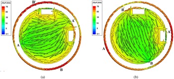
The characteristic modes of the proposed geometry have been examined using the commercial software FEKO [31]. In modal simulations, rectangles have been etched in the ground plane at orthogonal locations representing the loop-type GradiAnts without feed structures. The fundamental ground modes 1 and 2 are degenerate modes of the structure that are relevant to the proposed design and resonate at the same frequency. Figures 2(a) and 2(b) present the current distributions of modes 1 and 2, respectively. Mode 1 is excited in the direction AA’ where the current maxima on the bezel are at B and B’ as shown in Fig. 2(a). On the other hand, mode 2 is excited in the direction BB’ where the current maxima on the bezel appear at A and A’. By observing Figs 2(a) and 2(b), antenna 1 is located at the current maximum points of mode 1 and dominantly coupled with mode 1 for radiation, as can be expected from equation (3). Similarly, antenna 2 is strongly coupled with mode 2 for radiation.
Current distribution of degenerate characteristic modes of the reference design (without isolator) at 2.45 GHz (a) mode 1 (b) mode 2.

The resonance of the characteristic mode depends only on the shape and size of the ground plane, while the operating frequency of the GradiAnt elements is controlled using the lumped components Cr and Cf. Increasing the Cr lowers the operating frequency whereas Cf controls the impedance matching at the operating frequency, as investigated in [Reference Zahid and Kim19]. Though the antenna's operating frequency is different from the resonance of the characteristic modes, equation (3) shows that the coupling increases as the operating frequency of the antenna approaches the resonance of the ground mode, and the radiation performance of the antennas is proportional to the coupling (αm) between the antenna element and the ground mode.
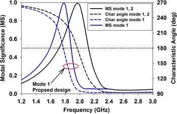
Meanwhile, the isolator is installed between the antenna elements where the branch is shorted with the ground plane at location A’. The capacitor is placed at the other branch, i.e. toward antenna 1. At this location, the isolator has negligible coupling with mode 2, however it couples strongly with mode 1. The impact of the isolator on the ground modes has been observed by plotting the modal significance and characteristic angle of the fundamental modes in Fig. 3. The figure shows that without the isolator, both modes resonate simultaneously at 2 GHz. Once the isolator is installed, the resonance frequency of mode 1 is lowered to 1.8 GHz whereas that of mode 2 remains unaltered. Increasing the value of Cc can further decrease the resonance frequency of mode 1.
Modal significances and characteristic angles of modes 1 and 2 with and without the proposed isolator.

Simulation results
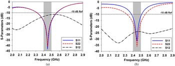
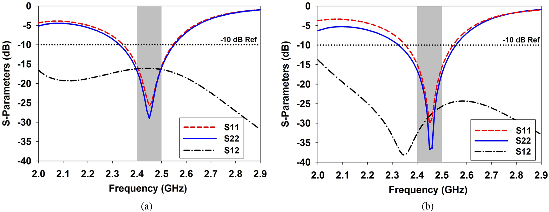
Full-wave simulations were conducted to observe the performance of the proposed design. In the reference design (without isolator), the simulated values of Cr and Cf of both antenna elements were 0.26 and 0.6 pF, respectively. In case of the proposed design, the optimized values of Cr 1, Cf 1, Cr 2, Cf 2, and Cc were 0.22, 0.48, 0.23, 0.7, and 0.23 pF, respectively. The simulated S-parameters of the reference and proposed antennas have been displayed in Figs 4(a) and 4(b), respectively. Figure 4(a) shows the S-parameters of the reference design where it can be observed that the matching bandwidth with reference to −10 dB of both antenna elements is 250 MHz (2.31–2.56 GHz). The peak isolation between the elements within the Wi-Fi band is −11.7 dB which occurs at 2.5 GHz. In case of the proposed design, the impedance bandwidth of antenna 1 is 130 MHz (2.38–2.51 GHz) and that of antenna 2 is 230 MHz (2.32–2.55 GHz), as shown in Fig. 4(b). In particular, the isolation bandwidth with reference to −20 dB is 950 MHz (1.98–2.93 GHz) whereas the isolation is <−22 dB within Bluetooth/Wi-Fi band. The matching bandwidth of the antenna is proportional to the coupling (αm) between the antenna element and the ground mode, as given in equation (3). The equation shows that the coupling can be enhanced if the operating frequency of the antenna approaches the resonance frequency of the ground mode. Furthermore, placing the antenna element at the maximum current location of characteristic current mode results in enhancement of αm that results in enhancement of matching bandwidth of the antenna element, as discussed in [Reference Zahid and Kim20].
Simulated S-parameters (a) reference antenna (b) proposed antenna.

A pertinent feature of the proposed design is that the isolation bandwidth can be further enhanced if the isolator is placed closer to antenna 2. Furthermore, the impact of the loop-type isolator on the bandwidth performance of antenna elements can also be inferred by the comparison of Figs 4(a) and 4(b). It is evident that the change in bandwidth of antenna 2 is insignificant due to minimal coupling between the isolator and mode 2. However, the bandwidth of antenna 1 has been decreased due to lowered ground mode resonance frequency. Satisfactorily, the desired band is adequately covered by both the antenna elements. The bandwidth of antenna 1 can be improved by increasing the angular separation between the antenna elements, discussed in the next section.
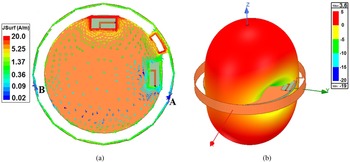
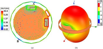
The operation mechanism of the proposed wideband decoupling technique can be further explained by observing the current density and radiation patterns as displayed in Figs 5 and 6. Figure 5(a) shows the current distribution when antenna 1 was excited. It is evident that the current excited by antenna 1 is strongly coupled with the isolator, thereby creating null at the port of antenna 2. The nulls on the bezel can be observed at points A and B where point B on the bezel appears close to antenna 2. Moreover, the resultant current distribution on the ground plane can be seen as a dipole-type antenna along the y-axis with a tilt in the xy-plane. Therefore, excitation of antenna 1 produces linearly polarized waves along the y-axis. The model can be confirmed by observing the 3D gain pattern in Fig. 5(b) where the simulated peak gain is 3.6 dBi. A similar effect can be seen when antenna 2 is excited as shown in Fig. 6(a). The resultant current distribution can be modeled as a dipole-type antenna along the x-axis with a minor tilt. Therefore, excitation of antenna 2 produces linearly polarized waves along the x-axis. The MIMO antenna exhibits polarization diversity as both antennas radiate orthogonally polarized waves. The corresponding radiation pattern is displayed in Fig. 6(b) where the peak gain is 3.8 dBi. The radiation pattern presents polarization diversity along the z-axis and pattern diversity in the xy-plane, which is a desired feature for MIMO applications.
Simulated fields when antenna 1 is excited (a) vector current density and (b) 3D radiation pattern.

Simulated fields when antenna 2 is excited (a) vector current density and (b) 3D radiation pattern.

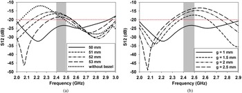
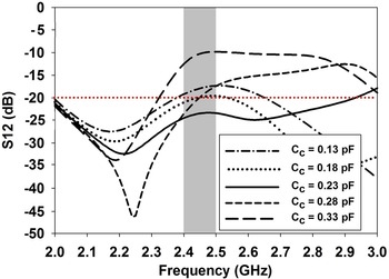
The coupling between the loop-type isolator and the bezel is a critical parameter providing good isolation over a wider bandwidth. The coupling can be controlled by the gap between the isolator and the bezel. The coupling was analyzed by increasing g in two ways. Firstly, the coupling between the bezel and isolator has been decreased by increasing the bezel diameter. It is evident from Fig. 7(a) that increasing the bezel radius worsens the isolation between the antenna elements. Secondly, the height of the isolator was decreased while keeping the bezel diameter fixed, and the observation is presented in Fig. 7(b). It is apparent that the isolation performance degrades significantly by increasing g. Therefore, isolation cannot be achieved if the loop-type isolator is embedded inside the ground plane. The effect of changing the value of Cc on isolation is shown in Fig. 8. It is observed that the isolation improves within the Wi-Fi band when the value of Cc is increased from 0.18 to 0.23 pF. However, as the value of Cc increases further to 0.33 pF, the isolation degrades in the desired band whereas the minimum value of the isolation curve shifts toward the lower frequencies. The observation indicates that the isolation can be controlled using Cc.
Effect on isolation performance with the variation in the gap by (a) increasing the diameter of the bezel and (b) decreasing the height of the isolator.

Effect on isolation with the increase in the values of Cc.

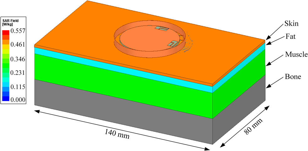
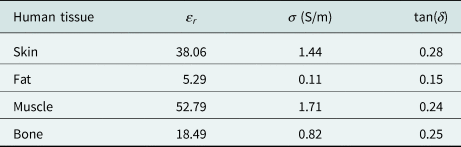
As indicated by the radiation patterns of Figs 5 and 6, the antenna radiates in z-axis, i.e. in the direction of human wrist. Therefore, the level of specific absorption rate (SAR) of the human body due to the proposed antenna radiation needs special attention. The average SAR has been calculated using full-wave simulations with the body parameter at 2.45 GHz that are listed in Table 1 [Reference Wang and Yan11, 31, Reference Zainud-Deen, Hassan and Malhat32, Reference Li, Gao, Bao, Yi, Song and Bian33] whereas the simulation model is presented in Fig. 9. The blood with permittivity and permeability 59.2 and 2.11, respectively, has already been considered in the material parameters for accurate modeling of human tissue model shown in Fig. 9 because it is inherent part of skin and muscle. It was observed that the average SAR was <0.56 W/kg which is well within the RF safety limits proposed by Federal Communication Commission (FCC) and European Telecommunication Standards Institute (ETSI) [34, Reference Yan and Vandenbosch35].
Simulation model of average SAR calculation.

Material parameters of human body model at 2.45 GHz

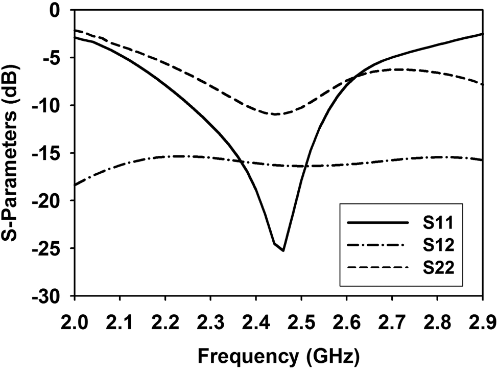
The simulations have been conducted to observe the impact of the proximity of human wrist on antenna performance. The resonance frequency was lowered as the antenna was mounted on the wrist model. Therefore, the lumped components were decreased to re-tune the antennas back to Wi-Fi band. The optimized values of Cr 1, Cf 1, Cr 2, Cf 2, and Cc were 0.215, 0.16, 0.6, 0.76, and 0.32 pF, respectively. The tuned S-parameters are displayed in Fig. 10. It can be noted that the bandwidths of both antenna elements have been increased due to the lossy wrist model. However, the difference between the return loss curved between antennas 1 and 2 is enlarged due to the asymmetry of the rectangular wrist model along x and y-axes.
Simulated S-parameters in the presence of human wrist model.

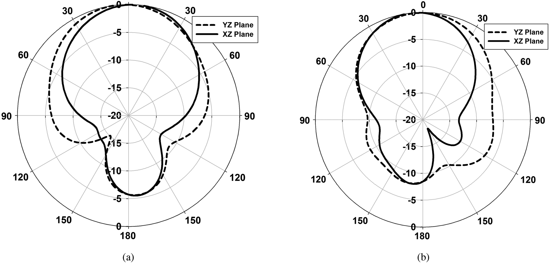
Although the isolation is increased in this case, interestingly however, the isolation curve is approximately flat at −16.5 dB. The observation indicates the robustness of the proposed wide band isolation technique. Figure 11 shows the simulated normalized radiation patterns in case of the antenna mounted on the wrist model. The gain in the z-axis was <−5 dB due to the presence of lossy wrist mode.
The simulated radiation patterns at 2.45 GHz when (a) antenna 1 was excited and (2) antenna 2 was excited in the presence of human wrist model.

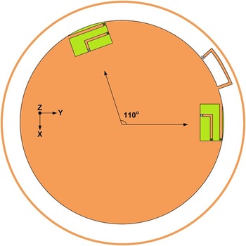
Antennas located at 110o angle
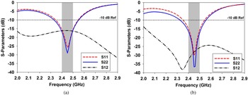
In order to demonstrate the versatility of the proposed technique, antenna 1 has been shifted to 110o with reference to antenna 2. The other configuration of the design remains the same as shown in Fig. 12. Once again, the proposed design has been compared with the reference design that is without the loop-type isolator. The results of full-wave simulations have been presented in Fig. 11. In the reference design (without isolator), the optimized values of Cr 1, Cr 2, Cf 1, Cf 2, and Cc were 0.26, 0.28, 2, 1.9 and 1 pF, respectively. In case of the proposed design, the simulated values were 0.27, 4.9, 0.38, 2.9, and 1.15 pF, respectively. Figure 13(a) shows that the impedance bandwidths of both antenna elements of the reference design are approximately the same, i.e. 220 MHz (2.33–2.55 GHz). The peak isolation between the elements within the target band is −16 dB which occurs at 2.45 GHz. In case of the proposed design, the matching bandwidths of antennas 1 and 2 are 190 and 230 MHz, respectively, as shown in Fig. 13(b). The data show that the bandwidth of antenna 1 is significantly improved in comparison with the previous case when antenna elements were orthogonal to each other. A noteworthy observation is that the isolation bandwidth has been dramatically improved that is 5 GHz (2.1–7 GHz) where the curve is <−25 dB within the Wi-Fi band. It was further observed in this case that the radiation patterns presented diverse behavior as observed in the previous case. Accordingly, regardless of the small size and high-Q properties of the loop-type isolator, it provides wideband isolation due to the proximity effect of the bezel in the proposed design.
The proposed technique with GradiAnt antennas 110 degrees apart.

Simulated S-parameters with antennas at 110° (a) reference and (b) proposed.
Measured results
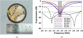
The simulation results were confirmed by fabricating the proposed antenna as shown in Fig. 14(a), where the antenna elements were orthogonal to each other. The fabricated values of Cr 1, Cr 2, Cf 1, Cf 2, and Cc were 0.16, 0.22, 0.75, 0.95, and 0.2 pF, respectively. The measured S-parameters are compared with simulated ones in Fig. 14(b). The measured impedance bandwidth of antenna 1 is 170 MHz (2.38–2.55 GHz) whereas that of antenna 2 is 300 MHz (2.31–2.61 GHz). The measured isolation bandwidth with reference to −20 dB is 770 MHz (2.2–2.97 GHz), verifying a wideband isolation performance of the proposed design. The simulation and measured results largely agree with each other. However, the minor deviation in the measured and simulated results is due to the fabrication tolerance.
(a) Fabricated antenna and (b) comparison of simulated and measured S-parameters.

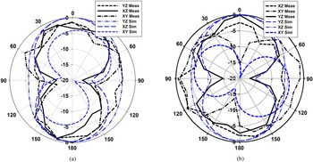
The radiation patterns of both antenna elements were measured in the anechoic chamber with dimensions 9 × 4.5 × 4.9 m3. During the pattern measurements, when antenna 1 was excited, antenna 2 was terminated at matched load and vice versa. The normalized simulated and measured patterns of both antennas are displayed in Fig. 15. The measured peak gains of antennas 1 and 2 were 3.1 and 3.3 dB, respectively. The measured average efficiency of the antennas at 2.45 GHz was 61.5%.
The measured radiation patterns at 2.45 GHz when (a) antenna 1 was excited and (2) antenna 2 was excited.

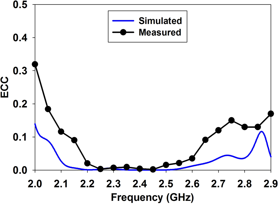
An important figure of merit for MIMO antenna performance is envelop correlation coefficient (ECC) expressed by ρe. The ECC was calculated using the measured radiation patterns by the following expression [Reference Vaughan and Andersen36, Reference Sharawi, Hassan and Khan37],

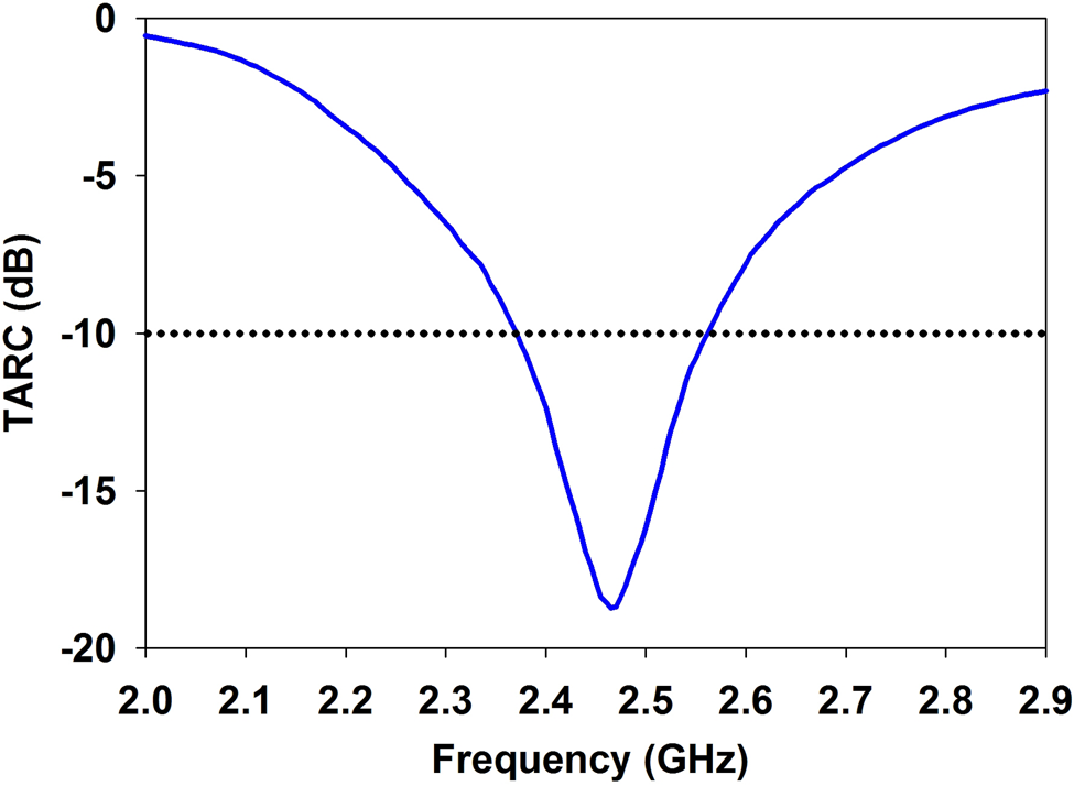
where Fi (θ, φ) represents the radiation pattern of the MIMO antenna when the ith port is excited. The measured and simulated ECC are plotted in Fig. 16 where it is evident that the ECC data are well below 0.1 in the entire Wi-Fi band. The total active reflection coefficient was calculated using the expression [Reference Sharawi, Hassan and Khan37]

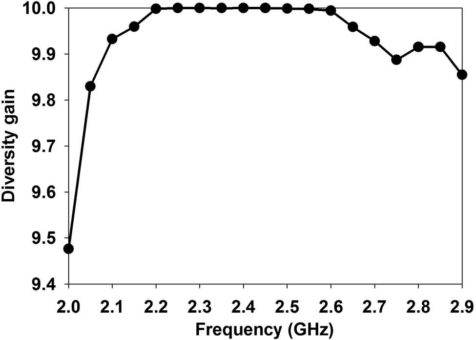
where ai and bi represent the incident and reflected wave signals, respectively. The TARC has been plotted in Fig. 17. The graph shows that the TARC is well below −10 dB in the operating band. The diversity gain (DG) was calculated using the following equation [Reference Sharawi, Khan, Numan and Aloi38],

The simulated and measured ECC.

Measured TARC of the MIMO antenna.

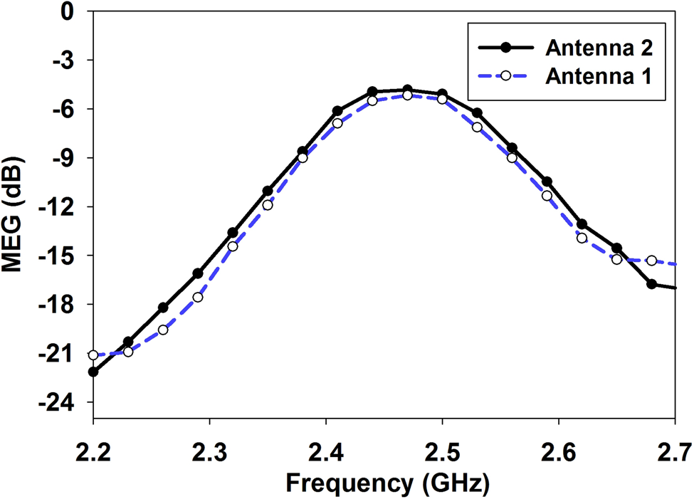
The measured DG values have been plotted in Fig. 18. The data depict that the DG is higher than 9.6 between both antenna elements, which indicates good MIMO performance. The mean effective gain (MEG) is another important figure of merit that indicates the performance of the MIMO antenna in a fading environment. The MEG has been calculated using the following equation [Reference Zahra, Awan, Ali, Hussain, Abbas and Mukhopadhyay39],

The measured diversity gain of the MIMO antenna.

The values of MEG closer to −3 dB are a good MIMO performance indicator. Figure 19 presents the measured MEG of the proposed antenna elements where the peak values of antennas 1 and 2 are −5.2 and −4.76 dB, respectively. Furthermore, the difference between MEG values of the two antennas is <0.5 dB.
The measured mean effective gain.

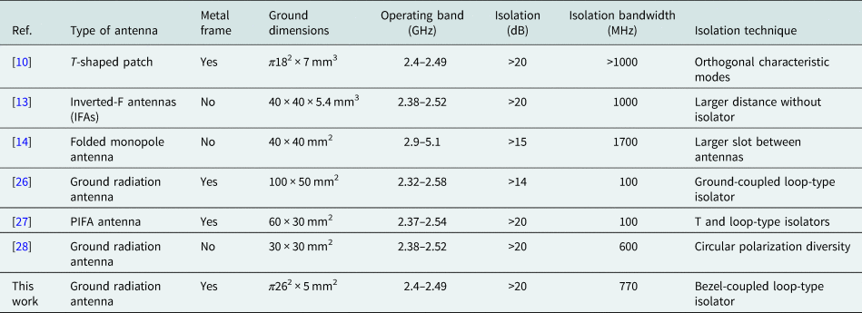
The performance of the antenna has been compared with the literature of Wi-Fi antennas in Table 2. It is evident from the table that the performance of the proposed antenna is better than [Reference Qu, Zhang and Kim26–Reference Qu, Piao, Qu, Kim and Kim28]. However, the isolation performance is lower in comparison with [Reference Wen, Hao and Wang10], [Reference Chen, Yang and Sin13], and [Reference Woo, Baek, Park, Kim and Choi14]. It is due to the fact that the articles used non-embedded antenna structures. The low-profile antenna structure is a critical demand of modern smartwatch application. Therefore, the main contribution of the proposed design is that higher isolation bandwidth has been achieved using the embedded antenna elements within the ground plane along with the coplanar isolator.
Comparison of the proposed deign with literature

Conclusion
In this work, a novel wideband isolation technique based on a bezel coupled loop-type isolator is proposed for the smartwatch MIMO application. The location as well as the gap between the isolator and bezel were used to achieve 770 MHz isolation bandwidth. The measured impedance bandwidths of both antenna elements are higher than 210 MHz and ECC is <0.1 in the entire Wi-Fi band. The interesting aspect of the technique is that it is not restricted to a specific angular separation between the antenna elements. The versatility is a desirable feature for smartwatch applications with metallic bezels, which makes the proposed design a promising candidate for current and future smartwatch MIMO applications.
 Babar Aslam Baloch received his M.S. degree from the College of Signals, National University of Sciences and Technology (NUST), Islamabad. He is currently pursuing his Ph.D. degree from the Department of Electrical Engineering, NUST.
 Longyue Qu received the B.S. degree in electronic engineering from Yanbian University, China, in 2013, and the M.S. and Ph.D. degrees in electromagnetics and microwave engineering from Hanyang University, Seoul, Rep. of Korea, in 2015 and 2018, respectively. He was a post-doctoral researcher at Hanyang University from September 2018 to August 2019 and then was promoted as an Assistant Research Professor. From 2019 to 2022, he was a co-founder and CTO of Hanyang Antenna Design Co. Ltd, Shenzhen, China. Since 2022, he has been an Assistant Professor with the School of Electronics and Information Engineering, Harbin Institute of Technology, Shenzhen, China. Dr. Qu is the author of more than 40 articles, and more than 30 inventions. He serves as a reviewer for several international journals and conferences. He also serves as an Editorial Board Member in the International Journal of Sensors, Wireless Communications and Control. His current research interests include antenna theory and design, metamaterial-based antenna technology, millimeter-wave arrays, and RF circuits. He was a recipient of the Korean Government Scholarship Award and China Scholarship Council (CSC). His research is listed in the Top 100 National R&D Excellence Award in 2015.
 Zeeshan Zahid received his Ph.D. from Hanyang University, South Korea in 2018. He is currently serving as an Associate Professor in the Department of Electrical Engineering, College of Signals, National University of Sciences and Technology, Pakistan. He has taught various courses such as electromagnetics, antennas and wave propagation, microwave engineering, and electronic circuit design. He is the recipient of Best Teacher Award in 2012. His research interests include high efficiency antenna design for mobile devices, circularly polarized antennas, and Massive MIMO for 5 G smartphones. He is an active researcher and has contributed a number of research papers, published in reputed journals. He is a senior member of IEEE and a member of IEEE antennas and propagation society (AP-S). He also serves as a technical reviewer of reputed international journals.
 Adnan A Khan did his B.E. in electrical (Telecomm) engineering from the National University of Sciences and Technology, Pakistan. He received his Master's degree in computer engineering from the University of Engineering and Technology, Taxila. He received his Ph.D. in computer engineering from the Centre of Advanced Studies in Engineering, affiliated with UET Taxila, Pakistan.