I. INTRODUCTION
Compact antennas with wideband and high-efficiency characteristics are essentially required to be used in wireless communication devices such as laptops and mobile phones. Epsilon-negative transmission lines (ENG-TL) has attracted researchers to design compact antennas due to its unique characteristics (antiparallel group and phase velocities, zero propagation constant at non-zero frequencies) [Reference Park, Ryu, Lee and Lee1–Reference Majedi and Attari4]. Niu et al. recently proposed wideband metamaterial (MTM) antenna using three numbers of unit cells and achieved 70% bandwidth [Reference Niu and Feng2]. Later on, by introducing backed ground plane concept by same authors [Reference Niu, Feng and Siu3] are succeed to design dual band and wideband antenna simultaneously with 67.4% fractional bandwidth. Majedi & Attari [Reference Majedi and Attari4] presented a qualitative structure based on ENG-TL approach and designed two different kind of antennas as dual band and dual polarized respectively by incorporating notches into the patch. Some works have been carried out based on composite right/left handed (CRLH) transmission lines to enhance the bandwidth by using symmetric coplanar waveguide (CPW)-fed [Reference Jang, Choi and Lim5] and asymmetric CPW-fed structures [Reference Niu and Feng6]. It has been observed from the studies that the asymmetric structure offers bandwidth enhancement due to increased shunt inductance incorporated with the CRLH transmission line. Moreover, modes can be introduced by combining the number of elements or unit cells into the structures, which are configurable with varying design dimensions of the elements [Reference Sharma and Chaudhary7–Reference Gupta, Sharma and Chaudhary8].
A novel CPW-fed zeroth-order resonant antenna has been reported in which a single resonant ring is employed to introduce another mode and is achieved 40% fractional bandwidth at 2.09 GHz [Reference Wang and Feng9]. Furthermore, a compact tri-band antenna is proposed by incorporating T-junction discontinuity based on the CRLH resonant structure [Reference Amani, Kamyab, Jafargholi, Hosseinbeig and Meiguni10]; however, shortcoming of this antenna is having negative gain in the lower band.
In this paper, a triple-stub CPW-fed metamaterial-inspired antenna is proposed. Equivalent circuit of the proposed antenna is presented and concluded that these stubs offer certain lumped parameters associated with the conventional ENG-TL. In addition to this coupling between these stubs introduce another mode, which is responsible for enhancing the bandwidth. The −10 dB bandwidth of 49.2% is achieved at 2.21 GHz. The proposed antenna is suitable for the operation at GSM 1900 (1.85–1.99 GHz), WLAN/Wi-Fi (2.4–2.5 GHz), Bluetooth (2.4–2.49 GHz), and WiMAX (2.5–2.7 GHz). All simulations are carried out by the Ansoft HFSS14.0 EDA tool.
II. ANTENNA THEORY
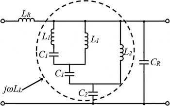
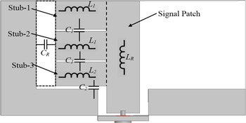
The design methodology of the proposed antenna is based on the ENG transmission line approach as series capacitance is not present (C L ). Figure 1 shows the intuitive equivalent circuit model for the proposed antenna. Figure 2 depicts the schematic of the proposed antenna with respect to modeling of lumped parameters, corresponding to equivalent circuit model given in Fig. 1. Signal patch is modeled by the series inductance L R . L 1 is associated with the inductance offered by the stub1 and stub2, respectively, since the dimensions of these stubs are same. Similarly the gap between stub-1, stub-2 and stub-2, stub-3 is modeled by the C 1. Moreover, L 2 is the inductance offered by stub-3, and C 2 signifies the gap between stub-3 and ground plane. Finally, whole stubs offer the combining capacitance C R , which is introduced by the gap between those stubs and ground plane as shown in Fig. 2.
Equivalent circuit model of the proposed antenna.

Modeling of the circuit elements in the proposed antenna.

The impedance offered by the specified region in Fig. 1, is calculated and is given by
 $$Z = \displaystyle{{j\omega \left\{ {A\left( {{L_2} - {C_2}} \right) - j\omega {L_2}{C_2}} \right\}} \over {A + j\omega L{}_2}},$$
 $$A = \displaystyle{{j\omega \left[ {{L_1}\left\{ {{L_1} - (1/{\omega ^2}{C_1})} \right\} - (1/{\omega ^2}{C_1})\left\{ {2{L_1} - (1/{\omega ^2}{C_1})} \right\}} \right]} \over {\left[ {2{L_1} - (1/{\omega ^2}{C_1})} \right]}},$$
Substituting (2) into (1) we obtain
 $$\eqalign{& Z = j\omega \left( {L_1^2 {L_2} - L_1^2 {C_2} - {L_2}{C_2}} \right) \cr & \qquad+ \displaystyle{1 \over {{{\left( \,{j\omega} \right)}^2}}}\left( {\displaystyle{{3{L_1}{L_2}} \over {{C_1}}} - \displaystyle{{3{L_1}{C_2}} \over {{C_1}}}} \right) + \displaystyle{1 \over {{{\left(\, {j\omega} \right)}^3}}}\left( {\displaystyle{{{L_2}} \over {C_1^2}} - \displaystyle{{{C_2}} \over {C_1^2}}} \right).} $$
It is perceived from (3) that equivalent impedance is inductive in nature as at high-frequency terms 2 and 3 can be neglected. It is also observed that the left-handed inductance (L L ) depends on the parameters L 1, L 2, and C 2. Therefore variation in dimensions of stubs and gaps controls the parameters involved in the left-handed inductance and thereby the resonant frequency [Reference Lai, Leong and Itoh11]. From (3) equivalent inductance is given by
 $${L_L} = \left( {L_1^2 {L_2} - L_1^2 {C_2} - {L_2}{C_2}} \right).$$
III. ANTENNA DESIGN AND ANALYSIS
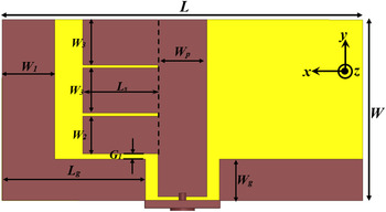
Figure 3 shows the configuration of the proposed antenna using three rectangular stubs along with the relevant design dimensions in captions. The whole antenna is fabricated on an FR4 Glass Epoxy substrate (ε r = 4.4, tanδ = 0.02) with 1.6 mm thickness.
Configuration of the proposed antenna (L = 48 mm, W = 24 mm, L g = 19.05 mm, W g = 5.5 mm, W 1 = 7 mm, W 2 = 5 mm, W 3 = 6 mm L s = 10 mm, W p = 6.5 mm, and G 1 = 0.7 mm).

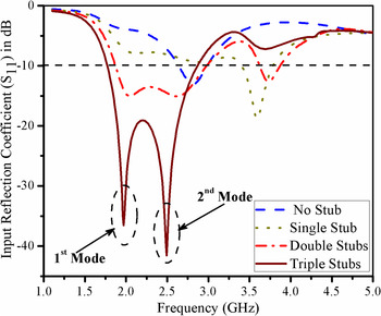
The proposed antenna is essentially an asymmetric CPW-fed ground plane structure in which three rectangular stubs are incorporated to ensure best impedance matching. In fact, these stubs provide different lumped parameters to realize an ENG transmission line as discussed in the previous section. Thus, by carefully optimizing the dimensions of the stubs, gap between CPW ground plane and stubs, compact antenna structure is obtained. Figure 4 indicates that resonant frequency is significantly decreased by increasing number of stubs. It is observed that second resonant mode is obtained by patch, while first mode is introduced by the coupling between two stubs which are also responsible for band broadening by merging two modes. It is important to note that triple stubs do not offer significant bandwidth improvement with respect to double stubs. In fact, the lumped components involved in third stub are responsible to manipulate the input impedance of the antenna; hence, impedance matching is prominently better as compared with double stubs.
Comparison of input reflection coefficients of the antenna with (a) no stub, (b) single stub, (c) double stubs, and (d) triple stubs.

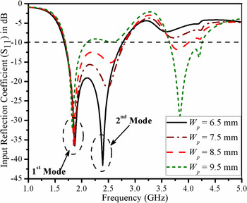
In order to verify the excitation of modes variation in input reflection coefficient by changing dimension W p is shown in Figure 5. It is observed that second resonant mode is getting extinct by increasing the W p . This is because as the width of the signal patch (W p ) is increased, the patch is getting closer to the CPW ground plane, which affects the coupling between patch and CPW ground planes.
Input reflection coefficients of the proposed antenna by varying W p .

IV. EXPERIMENTAL RESULTS
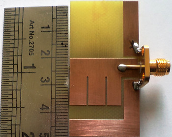
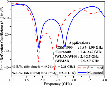
Figure 6 shows the photograph of the fabricated prototype. Input reflection coefficients (S 11) measurement has been carried out by using Anritsu VNA master MS2025B. Good agreement in the simulated and measured input reflection coefficients has been observed as shown in Fig. 7, with small shift in center frequency. This is because of non-uniform substrate and imperfection in soldering.
Photograph of the fabricated prototype.

Simulated and measured input reflection coefficients of the proposed antenna.

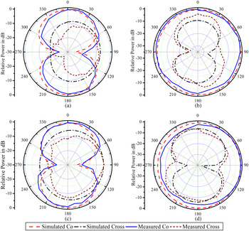
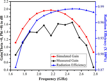
Figure 8 shows the simulated and measured radiation patterns of the proposed antenna at two resonant modes, obtained by the simulation. It is observed that radiation patterns are consistent throughout the bandwidth and exhibits dipolar-type radiation pattern in the xz-plane (E-plane), while omnidirectional type pattern in the yz-plane (H-plane). Measured radiation patterns are in good agreement with the simulated one, except minor asymmetry in cross-polarization. Radiation characteristics of the prototype are carried out in free space environment by using log periodic antenna as a reference antenna. Cross-polarizations are affected by the radiations from the free space without absorbers. Figure 9 shows the peak gain and radiation efficiency profile for the proposed antenna. This antenna offers simulated peak gain of 1.73 and 1.27 dB at the first and the second resonant mode. The radiation efficiencies are 94.4 and 98.3% corresponding to the observed mode. One can see that the measured gain observed in Fig. 9 is lower than that of the simulated gain. It may be due to the interference by the free space radiation resulting deterioration in received power.
Simulated and measured radiation patterns of the proposed antenna. (a) xz-plane at 1.87 GHz, (b) yz-plane at 1.87 GHz, (c) xz-plane at 2.39 GHz, (d) yz-plane at 2.39 GHz.

Gain and radiation efficiency profiles of the proposed antenna.

V. CONCLUSION
A compact CPW-fed metamaterial-inspired antenna based on ENG-TL is proposed in this paper. To improve the bandwidth and impedance matching, rectangular stubs have been used. It is observed that an extra resonant mode is introduced due to the coupling between two stubs and another stub is used to improve impedance matching. Thus, a fractional bandwidth of 49.2% is achieved at center frequency 2.21 GHz. The far-field parameters are consistent throughout the operating band. This antenna can cover GSM 1900 (1.85–1.99 GHz), WLAN/Wi-Fi (2.4–2.5 GHz), Bluetooth (2.4–2.49 GHz), and WiMAX (2.5–2.7 GHz) to be used in mobile phones and laptops.
ACKNOWLEDGEMENTS
The authors would like to thank Mr. Rohit Kumar Saini, Ph.D. student, ISM Dhanbad for providing assistance in far-field measurements. The authors also express their gratitude to Mr. Naveen Mishra, Ph.D. student, ISM Dhanbad for improving the literature of the paper.
 Ashish Gupta was born on 4th August 1986. Currently, he is pursuing Ph.D. from Department of Electronics Engineering, Indian School of Mines, Dhanbad. He did his M. Tech. from Shri Govindram Seksaria Institute of Technology and Science, Indore in 2010, where he got fellowship from MHRD Govt. of India. He won the best paper award in ICAICV-2010 at Coimbatore. He has done his B. Tech. from Rustumji Institute of Technology, B. S. F. Academy, Tekanpur in 2008. From 2010 to 2013, he has been an Assistant Professor in private engineering institutes in Gujarat, India. He is the author of more than ten articles in the relevant area. His current research interests involve Metamaterials and its applications in active and passive devices.
 Dr. Raghvendra Kumar Chaudhary is working as an Assistant Professor at the Department of Electronics Engineering, Indian School of Mines, Dhanbad, India. He did his Ph.D. from Indian Institute of Technology Kanpur, India in January 2014, the M.Tech. degree from Indian Institute of Technology (BHU), Varanasi, India, in 2009 and the B.Tech. degree from Institute of Engineering and Technology, Kanpur University, India, in 2007. Dr. Chaudhary has authored more than 65 referred Journal and Conference papers. He was the recipient of the International Travel Grant form CSIR, DST, and IIT Kanpur, India. He was the recipient of the Best Student Paper Bronze Award at IEEE APACE, Malaysia in 2010 and also recipient of the Best Paper Award at ATMS, India in 2012. He is a member of IEEE and potential reviewer of many journals and conferences such as IEEE Transactions on Antennas & Propagation, IEEE AWPL, IET MAP, APS/URSI, etc. His current research interests involve Metamaterials, Dielectric Resonators, and computational electromagnetics.