I. INTRODUCTION
As structural engineering materials, particulate-reinforced Al composites have been obtaining more and more attraction in aerospace and automobile industries due to their low density and high mechanical properties.Reference Tjong and Ma1 A large number of different particle reinforcements have been applied in the fabrication of Al composites, such as Al2O3,Reference Yang, He, Chen, Cong and Ye2 SiC,Reference Chen, Shue, Chang and Lin3 TiC,Reference Liu, Han and Li4 Si3N4,Reference Xiu, Chen, Wu, Yang and Liu5 AlN,Reference Liu, Cong and Cheng6 TiB2,Reference Fan, Yang and Zhang7 etc. Most of the reinforcements mainly focus on the ceramic phases due to their light weight and stability in the aluminum melt. With the development of the particulate-reinforced Al composites, Al3Ti, one promising particle-reinforcement has been analyzed in our former work.Reference Liu, Han and Li8,Reference Liu, Han and Li9 Al3Ti has its own particular characteristics, such as low density (3.4 g cm−3), high Young's modulus (220 GPa), and excellent mechanical properties at both ambient and elevated temperatures.Reference Wright, Rabin and McFerran10,Reference Zhang, Xiao, Wang and Ma11 In addition, it has been reported that Al3Ti is a more powerful nucleating substrate for Al alloy than the above-mentioned ceramic particles,Reference Zhang, Kelly, Easton and Taylor12 meaning that Al3Ti can decrease the grain size of Al effectively.
Generally, the performance of particulate-reinforced Al composites is directly influenced by the combination of the properties of the reinforcement, matrix, and their interface. Small size of the reinforcement, small grain size of matrix, and clean interface are always recommended for better mechanical properties. Based on this principle, Al3Ti particles can be regarded as a promising reinforcement in Al composites. On the one hand, microsized Al3Ti particles can be obtained by using direct reaction between the solid Ti powders, or some salts containing Ti element and Al melt. The formation of in situ Al3Ti particles undergoes the processes of nucleation and growth in the Al melt, thereby a clean interface between the reinforcement and matrix can be guaranteed. On the other hand, in situ formed Al3Ti particles can optimize the morphology of α-Al crystals of the Al matrix, which is the most advantageous effect of Al3Ti particles compared with other in situ formed reinforcements.
In situ formed Al3Ti has some unique characteristics as the reinforcement phase. However, some basic research on Al3Ti particles in Al alloy matrix is limited, such as their formation and evolution during the fabrication process from the pre-pouring to the solidification. We think more work should be carried out in this field to develop and enrich particulate-reinforced Al composites.
In this research, common K2TiF6 salt powder used as a reagent instead of Ti powder was added into the molten 7075 alloy to form Al3Ti particles. This research is mainly focused on the formation of in situ Al3Ti particles and their effects on the microstructure and properties of 7075 alloy, so no heat treatment was done to the as-cast samples. The aim of the research is to develop the usage of in situ formed Al3Ti particles as the reinforcement in the fabrication of Al composite materials and introduce a simple and low cost method to fabricate particulate-reinforced Al composites.
II. EXPERIMENTAL
A. Fabrication of samples
7075 alloy and K2TiF6 salt powders were used as the matrix and reagent, respectively. The chemical composition of 7075 alloy is presented in Table I. A 500 g 7075 ingot was heated up to 750 °C inside a graphite crucible placed in an electrical resistance furnace. When the molten 7075 alloy reached the constant temperature of 750 °C, K2TiF6 salt powders were added into the melt. The melt was stirred manually by using a graphite bar to avoid the aggregation of in situ formed Al3Ti particles in the melt. Manually stirring was carried out every 5 min. After 30 min, the slug on the melt surface was removed before pouring the melt into a steel mold for solidification. The amount of K2TiF6 salt powders added to the melt was such to form 7075 alloy—5 wt.% Al3Ti (after calculation, around 47 g K2TiF6 salt was used). A control sample without the addition of K2TiF6 was also produced by using the same experimental parameters.
Chemical composition of 7075 alloy.

B. Making tensile specimens
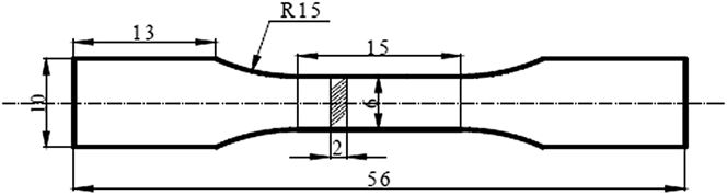
In situ Al3Ti/7075 alloy sample and the control sample were both cut by using wire-electrode cutting machine according to the dimensions shown in Fig. 1. All the tensile specimens were obtained from the central area of the ingots along the length direction. The surface of the tensile specimens was polished by sand paper to eliminate cutting marks.
Dimensions of the tensile specimen (in mm).

C. Materials analysis
1. Phases analysis
Phases formed during the fabrication were analyzed by x-ray diffraction (XRD; Bruker D8, Bruker, Madison, WI) using Cu Kα radiation at 40 kV and 40 mA and a scan rate of 0.015°/s. Both control and composite samples were both examined by XRD.
2. Microstructural analysis
The microstructural features of control and composite samples were observed by using scanning electron microscope (SEM, EVOMA15, ZEISS, Oberkochen, Germany) equipped with energy dispersive spectroscope (EDS) for analyzing the components. Fracture surfaces of the tensile test specimens were also examined by SEM. In addition, the microstructures of 7075 alloy with and without particle-reinforcement were observed by using optical microscopy (OM) after etched by using 0.5 wt.% HF solution for 30 s. The evolution of the morphology and size of α-Al crystals in 7075 alloy was mainly focused in this article.
D. Mechanical properties test
1. Hardness test
Brinell hardness (HRB) of each sample was tested by using hardness tester (HBRV-1875, Huaxia, Weifang, China) with a 1/16 inch diameter indenter under 100 kg load. To reduce the possible segregation effects, 10 measurements were taken from each sample to calculate the average value.
2. Tensile test
Tensile test was carried out by using tensile tester (WDW-200E, Tengjie, Jinan, China) at a speed of 1 mm/min at room temperature to obtain the ultimate tensile strength (UTS) and yield strength (YS) of the samples.
III. RESULTS AND DISCUSSION
Since the melting point of K2TiF6 is 682 °C, after adding the salt powders into the molten 7075 melt at 750 °C, the powders quickly dissolved into the melt. Meanwhile, the melt surface turned red, and the temperature of the melt exceeded 830 °C measured by the thermocouple, indicating that plenty of heat was generated due to the following exothermal reaction between the salt and aluminum.
 $${\rm{ 3}}{{\rm{K}}_{\rm{2}}}{\rm{Ti}}{{\rm{F}}_{\rm{6}}}{\rm{ + 13Al}} \to {\rm{3A}}{{\rm{l}}_{\rm{3}}}{\rm{Ti + 3KAl}}{{\rm{F}}_{\rm{4}}}{\rm{ + }}{{\rm{K}}_{\rm{3}}}{\rm{Al}}{{\rm{F}}_{\rm{6}}}\quad .$$
A. XRD analysis
Figure 2 shows the XRD patterns of in situ Al3Ti/7075 alloy and the control 7075 alloy, respectively. For in situ Al3Ti/7075 alloy, newly formed Al3Ti phase was detected according to its diffraction peaks. It means that the above reaction occurred after adding K2TiF6 salt powders into the molten 7075 melt. Some other intermetallic phases containing alloying elements of Al, Cu, Mg, and Zn were also formed during the solidification.
XRD patterns of in situ Al3Ti/7075 alloy and 7075 alloy.
B. SEM microstructural analysis
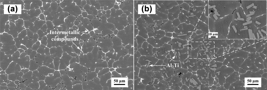
Figure 3 shows the typical microstructures of the control 7075 alloy [Fig. 3(a)] and in situ Al3Ti/7075 alloy [Fig. 3(b)], respectively. Most of the newly formed Al3Ti particles were rod-like in morphology, with the mean length and width of 15 µm and 5 µm, respectively. The formation of Al3Ti particles underwent the nucleation and growth processes, and it had preferred growth along <110> direction. John et al.Reference St. John and Hogan13 indicated that for the growth of Al3Ti particles, the growth rate anisotropy can be adequately accounted for by a marked difference in the rate of atomic attachment to the major crystallographic planes. The analysis of atomic attachment kinetics by JacksonReference Jackson14 suggested that, for a given crystal species, growth rate in a given crystallographic direction is related to the planar density normal to that direction, and nucleation of new atomic layers is easier on the lower density planes. Al3Ti phase has the lowest density on (110) plane, thereby the growth of Al3Ti favors <110> direction. As a result, the rod-like structure was the main morphology for Al3Ti particles after solidification. These Al3Ti particles were mainly located inside the α-crystals, with a few Al3Ti particles existing in the same aluminum grain, suggesting that the in situ formed Al3Ti particles played the role of nuclei during the solidification. In addition, intermetallic phases composed of alloying elements of Al, Cu, Mg, and Zn were formed in the boundaries of α-Al dendrites during the solidification process in the two samples [Figs. 3(a) and 3(b)], which was in good agreement with the result of XRD test (Fig. 2).
Typical microstructures of samples: (a) 7075 alloy and (b) in situ Al3Ti/7075 alloy.
C. Optical microstructural analysis
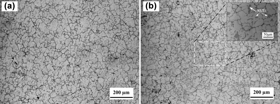
Figure 4 shows microstructures of the control 7075 alloy [Fig. 4(a)] and in situ Al3Ti/7075 alloy [Fig. 4(b)], including the morphology and size of α-Al crystals in the two samples. It is obvious that the addition of in situ formed Al3Ti particles could change the morphology of α-Al crystals from dendrite to equiaxed structure. Meanwhile, the size of α-crystals was reduced noticeably. For 7075 alloy, the size of most α-Al crystals was around 100 µm, and a few large particles were about 200 µm. For in situ Al3Ti/7075 alloy, the related values of the two sizes were decreased to 50 µm and 100 µm, respectively. In addition, for in situ Al3Ti/7075 alloy, it should also be mentioned that a few Al3Ti particles existed in one α-Al crystal [Figs. 3(b) and 4(b)], indicating that more than one Al3Ti particle might play the nucleating effect in one Al grain during the solidification process.
OM images of samples: (a) 7075 alloy and (b) in situ Al3Ti/7075 alloy.
D. Formation of in situ Al3Ti particles
Based on the results of XRD and EDS, it is clear that only Al3Ti phase was formed in the molten 7075 alloy melt according to reaction (1). No evidence has been found that other alloying elements participated in or influenced this reaction. Thereby, to simplify the analysis the evolution of K2TiF6 salt in 7075 melt, K2TiF6–Al system was considered only, without considering other alloying elements in the melt.
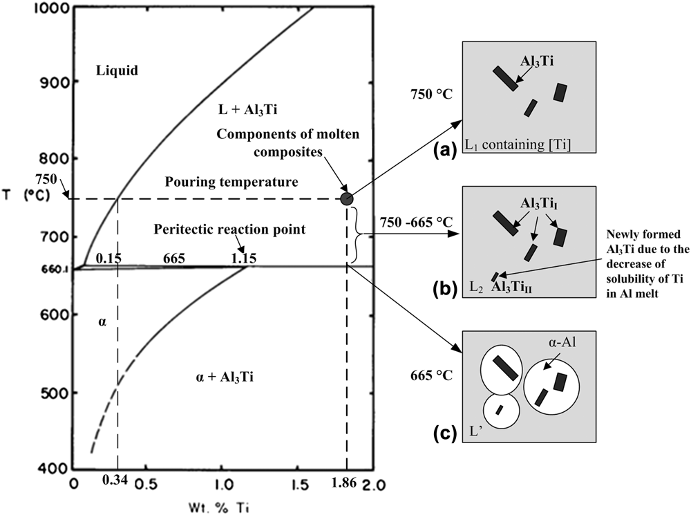
By calculation, the total weight percent of Ti element from K2TiF6 was around 1.86 wt.% in the composite. The melting point of K2TiF6 is 682 °C, and it started to melt as long as it contacted with the melt at 750 °C, resulting in the dissolution of Ti atoms into the Al melt. According to the Al–Ti phase diagramReference Sigworth15 (Fig. 5), Ti element has a rather low solubility in Al melt, and most of the Ti atoms will react with Al atoms to form Al3Ti phase. After holding for 30 min, the slug on the melt surface was removed before pouring the melt. The pouring temperature was designed at 750 °C. At this time, Ti element in the melt mainly existed in two forms: one was the solid Al3Ti particles, and the other one was dissolved Ti atoms in the melt with the weight percent of 0.34%, as shown in Fig. 5(a). Actually, the solid Al3Ti and the dissolving Ti in the molten Al melt at 750 °C have the following dynamic equilibrium chemical reaction.
 $${\rm{Al}}_3 {\rm{Ti}}_{{\rm{solid}}} \buildrel {750^\circ {\rm{C}}} \over \longleftrightarrow 3[{\rm{Al}}] + [{\rm{Ti}}]\quad .$$
Aluminum-rich corner of the Al–Ti phase diagramReference Sigworth15 and the status of in situ formed Al3Ti particles during different steps: (a) pre-pouring stage (750 °C), (b) cooling stage (750–665 °C), and (c) solidification stage (665 °C).
As the temperature increases, the reaction moves right and vice versa. After the melt was poured into the steel mold, the temperature of melt decreased to 665 °C quickly. In the temperature range of 750–665 °C, the Ti solubility in aluminum reduced significantly as the temperature decreased, and the related weight percent of Ti atoms in the aluminum melt was decreased from 0.34% to 0.15%, as shown in Fig. 5(b). As a result, more Ti atoms precipitated from liquid aluminum melt, leading to the formation of Al3Ti phase, as shown in Eq. (3). As a result, two types of Al3Ti particles were contained in the final aluminum composites after solidification: one was directly formed from the reaction, leading to the formation of large size Al3Ti particles named as (Al3Ti)I, and the other one was generated due to the decrease of the melt temperature, resulting in the formation of small size Al3Ti particles named as (Al3Ti)II.
 $$3[{\rm{Al}}] + [{\rm{Ti}}]\buildrel {750 \to 665^\circ {\rm{C}}} \over \longrightarrow {\rm{A}}{{\rm{l}}_3}{\rm{Ti}}{({\rm{II}})_{{\rm{solid}}}}\quad .$$
Furthermore, based on the Al–Ti phase diagram, the contents of each type of Al3Ti particles existed in the matrix can be calculated as follows
 $${\rm{Conten}}{{\rm{t}}_{{{{\rm{(A}}{{\rm{l}}_{\rm{3}}}{\rm{Ti)}}}_{\rm{I}}}}} = {{1.86 - 0.34} \over {1.86 - 0.15}} \times 100\% = 88.9\% \quad ,$$
 $${\rm{Content}}_{{\rm{(Al}}_{\rm{3}} {\rm{Ti)}}_{{\rm{II}}} } {\rm{ }} = {\rm{ }}1 - {\rm{Content}}_{{\rm{(Al}}_{\rm{3}} {\rm{Ti)}}_{\rm{I}} } {\rm{ }} = {\rm{ }}11.1\% \quad .$$
As the temperature of Al melt decreased to 665 °C, the solidification occurred, and all the in situ formed Al3Ti particles were located in the Al matrix, as shown in Fig. 5(c).
E. Refining mechanism analysis of Al3Ti particles
As mentioned above, both types of Al3Ti particles had the rod-like morphology, and these Al3Ti particles were present inside α-Al crystals. In the meantime, the grain size of in situ Al3Ti/7075 was much smaller compared with the original 7075 alloy, suggesting that in situ formed Al3Ti particles can be an effective nucleating agent which refines 7075 alloy during the solidification process.
For refining a material in terms of the heterogeneous nucleation, the interfacial energy between the nucleating substrate and the solid matrix is critical to the potency of the substrate. In the heterogeneous nucleation, the energy on the newly formed interface should be lower than that of the same area of the interface which formed directly in the liquid metal. To obtain the low interfacial energy, the substrate and the solid have to be coherent or partially coherent. The lattice matching between two solids can be evaluated by the following equationReference Li and Wu16
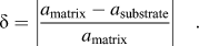 $$\delta = \left| {{{{a_{{\rm{matrix}}}} - {a_{{\rm{substrate}}}}} \over {{a_{{\rm{matrix}}}}}}} \right|\quad .$$
where δ is the value of lattice misfit between the matrix and the substrate, a matrix and a substrate are the lattice constants of the matrix and the substrate, respectively. Generally, when δ ≤ 0.05, the interface between the substrate and the matrix is coherent; when 0.05 < δ <0.25, the interface between the substrate and the matrix is partially coherent.
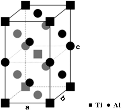
Al3Ti crystal has a tetragonal structure with a = b = 0.385 nm and c = 0.861 nm.Reference Li, Wang, Zhao, Chen, Chen and Chen17 Each unit cell contains 2 Ti atoms and 6 Al atoms, and the crystal structure of Al3Ti is shown in Fig. 6. α-Al crystal has a fcc structure with a = b = c = 0.404 nm.Reference Sigworth15 Thereby, the values of the lattice misfit between the Al and Al3Ti in both a and c directions are 0.049 and 0.065, respectively. Obviously, in situ formed Al3Ti phase has a good lattice matching with aluminum. Based on this theory, Al3Ti particles can work as the effective heterogeneous nucleation sites for primary aluminum in the solidification, which is demonstrated in this work. Furthermore, Zhang et al. used the edge-to-edge matching model based on the excellent atomic matching between Al3Ti and Al matrix to identify that Al3Ti is the best grain refiner for Al alloys compared with TiC, TiB2, and AlB2.Reference Zhang, Xiao, Wang and Ma11
The crystal structure of Al and Al3Ti.Reference Wang, Jha and Brydson18
In addition, according to Al–Ti phase diagram, when the temperature cools down to 665 °C, the following peritectic reaction will take place.
 $${\rm{L}} + {\rm{A}}{{\rm{l}}_3}{\rm{Ti}}\buildrel {665^\circ {\rm{C}}} \over \longrightarrow \alpha {\rm{Al}}\quad {\rm{.}}$$
Generally speaking, for the peritectic reaction, newly formed phase precipitates and grows on the solid phase. Thereby, the solid phase in the peritectic reaction always has a strong nucleating effect. In our research, all in situ Al3Ti particles were located inside Al grains, suggesting that Al3Ti particles were the nucleating substrates for Al matrix during the solidification.
Another possible reason for decreasing the Al grain size proposed by some researchersReference Sigworth19,Reference Wang, Liu, Qiu, Taylor, Easton and Zhang20 was that the refinement in aluminum might be related to the role of solute segregation of dissolved Ti in Al melt in front of the liquid–solid interface in restricting growth of grains and developing constitutional supercoiling providing a driving-force to activate further nucleation during freezing.
F. Mechanical properties of samples
1. Hardness
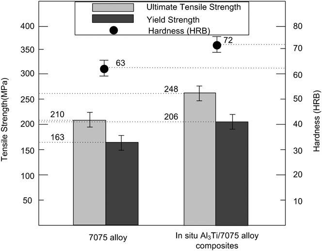
Figure 7 shows the Rockwell B-Scale hardness of as-cast 7075 alloy and in situ Al3Ti/7075 alloy composite. The average values of hardness of the above two samples were 63 and 72 (improved by 14.3%), respectively. The improved hardness of Al3Ti/7075 alloy composite, on the one hand, was attributed to the existence of some hard Al3Ti particles in the matrix. On the other hand, the decrease in the size of α-Al crystals also played an important role in increasing the hardness. For the material with a certain size, smaller grain size means more grain boundaries, leading to blocking the motion of dislocation more effectively during the deformation. In our research, the grain size of 7075 alloy containing in situ formed Al3Ti particles was much smaller than that of the original 7075 alloy. Consequently, the hardness of alloy was improved.
Mechanical properties of the samples, including hardness and tensile strength.
2. Tensile strength
Figure 7 also shows the tensile strength of 7075 alloy with and without Al3Ti particles, including the UTS and YS, respectively. The average UTS and YS of the original 7075 alloy and in situ Al3Ti/7075 alloy were 210 MPa, 163 MPa and 248 MPa (increased by 18.1%), 206 MPa (increased by 25.8%), respectively. It is obvious that in situ formed Al3Ti particles can increase the tensile strength of 7075 alloy.
In the particulate-reinforced composites, although the matrix material undertakes the main load during the deformation, the particles inside the matrix undertake some load as well, and hinder the distortion of matrix. From this viewpoint, when dislocations slip to the interfaces of particles and matrix, the movement of dislocations is blocked, leading to the stress concentration at the particles. Thereby, improved UTS can be obtained.
The strengthening mechanisms for YS used in the particulate-reinforced metal matrix composites have been discussed in several publications.Reference Zhang and Zhou21,Reference Kamat, Hirth and Mehrabian22 Generally, the improved tensile strength was attributed to the following reasons. One is based on the load transferring effect, in which the YS of composites (σcy) can be expressed asReference Nardone and Prewo23
 $${\sigma _{{\rm{cy}}}}{\rm{ }} = {\rm{ }}{\sigma _{{\rm{my}}}}[{V_{\rm{f}}}(s + 2)/2 + (1 - {V_{\rm{f}}})]\quad ,$$
where σcy is the YS of the composite, σmy the YS of the matrix, V f the volume fraction of the reinforced particles, and s the aspect ratio of the reinforced particles.
It is obvious that in the ideal situation, the YS of particulate-reinforced composite should be improved after adding some reinforced particles. In our research, after calculation and measurement, the volume fraction (V f) and the ratio aspect (s) of in situ formed Al3Ti particles in the matrix were around 4% and 3%, respectively. The YS of 7075 alloy was 163 MPa. Substituting the above data into Eq. (8), the YS of the composite was around 173 MPa, which was less than the real YS of in situ Al3Ti/7075 alloy.
Based on the above calculation, it is clear that the improved YS of composite was also attributed to other factors. We believe that the fine-grain strengthening mechanismReference Smith and Hashemi24 can be used to explain the improvement of YS of Al3Ti/7075 alloy. Due to the role of heterogeneous nucleation of in situ formed Al3Ti particles, the size of α-Al crystals in 7075 alloy can be reduced obviously. With the decrease of the grain size, more grain boundaries can be obtained. Grain boundaries strengthen the metals by acting as barriers to dislocations movement during the deformation, showing great YS of materials. Furthermore, the well-known Hall–Petch equationReference Sigworth19 is an empirical equation that relates the YS of a metal, σy, to its average grain diameter d as follows
 $$\sigma _{\rm{y}} {\rm{ }} = {\rm{ }}\sigma _0 + Kd^{ - \raise.5ex\hbox{$\scriptstyle 1$}\kern-.1em/ \kern-.15em\lower.25ex\hbox{$\scriptstyle 2$} } \quad ,$$
where σ0 and K are constants related to the materials of interest. The equation clearly shows that as grain diameter decreases, the YS of the material increases. However, the exact value has not been calculated in our research, since the values of σ0 and K of 7075 alloy have not been reported yet.
After analysis, we conclude that the decrease in grain size probably makes a greater contribution to the improved YS compared with the effect of the load transferring generated by particles in the matrix.
G. Fracture surface analysis
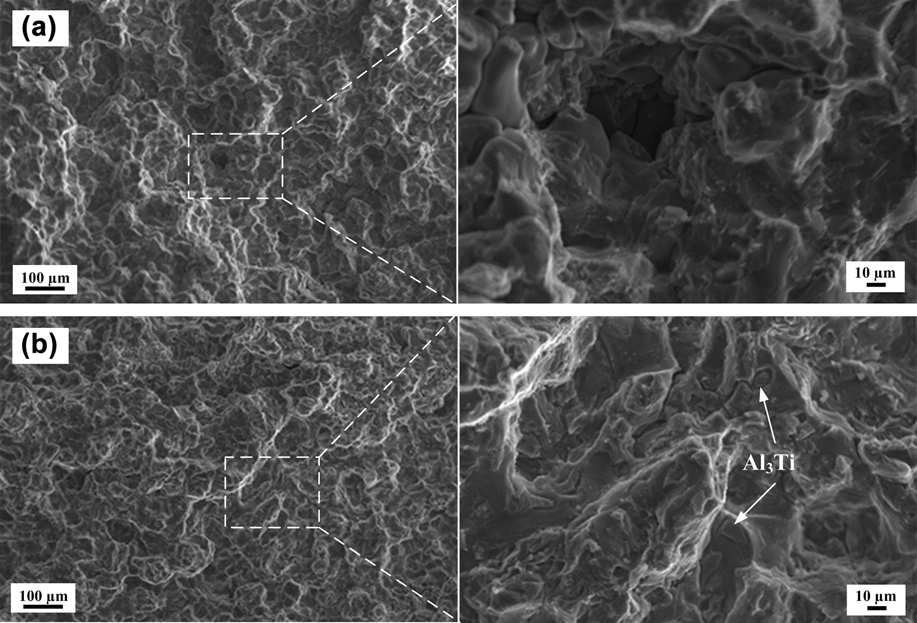
To further analyze the tensile strength of samples, fracture surfaces of the tensile specimens were observed by SEM as well. For the original 7075 alloy [Fig. 8(a)], it has brittle and plastic mixed fracture surface. Some obvious tear ridges existed on the fracture surface, indicating that quasi-cleavage fracture was one type of fracture. Furthermore, α-Al crystal with clean surface was also found, suggesting that partially intergranular fracture occurred during the tensile test. Generally, brittle fracture can occur easily in an intergranular manner if the grain boundary regions were embrittled by the segregation of some brittle intermetallic phases, for cracks were easily generated and propagated along the grain boundaries. Thereby, intermetallic fracture would decrease the tensile strength of the material to some extent.
SEM images of the tensile fracture surfaces of the samples: (a) 7075 alloy and (b) in situ Al3Ti/7075 alloy.
In situ Al3Ti/7075 alloy [Fig. 8(b)] also has brittle and plastic mixed fracture surface. Compared with 7075 alloy, more tear ridges existed on the fracture surface of Al3Ti/7075 alloy, suggesting that quasi-cleavage fracture was the main type of fracture form for Al3Ti/7075 alloy. In the meantime, the intergranular fracture was not found in Al3Ti/7075 alloy. As the grain size decreases, the total length of the grain boundaries increases, leading to smaller fraction of the brittle intermetallic phases in the grain boundary. Thereby, the tensile strength of the material increased during the deformation. Another important feature for Al3Ti/7075 alloy that should be mentioned is that some in situ formed Al3Ti particles were found inside the α-Al crystals, suggesting these particles were the nucleating agents during the solidification.
IV. CONCLUSIONS
In this research, in situ Al3Ti/7075 alloy was fabricated by adding K2TiF6 salt powders into the molten 7075 alloy by using casting method. In situ formed Al3Ti particles in 7075 alloy matrix were investigated, including their formation and effects on the microstructural evolution of Al alloy matrix and the mechanical properties. The following conclusions are drawn.
(1) In situ formed Al3Ti particles had rod-like morphology, with the average length and width of 15 µm and 5 µm, respectively. Besides working as the reinforcement, Al3Ti particles can serve as an effective nucleating agent in Al alloys. All Al3Ti particles were located inside α-Al crystals after solidification.
(2) In situ formed Al3Ti particles could optimize the microstructure of 7075 alloy: α-Al crystals of 7075 alloy changed from dendritic to equiaxed morphology, and the grain size decreased as well, leading to improved hardness, UTS, and YS of 7075 alloy.
ACKNOWLEDGMENTS
The authors are very grateful to the New Material Institute of Shandong Academy of Sciences for proving experimental equipment for this research. The authors also acknowledge Xu Wang, Jianhua Wu, Yunteng Liu, Haihua Zhuang, Jixue Zhou, and Chengwei Zhan from the New Material Institute for their help in this research.