I. INTRODUCTION
Nanostructured metallic materials exhibit superior strength and hardness compared with their coarse-grained counterparts. Severe plastic deformation (SPD) is one of the most promising approaches utilized to synthesize nanomaterials and includes equal-channel angular pressing, Reference Jahadi, Sedighi and Jahed1,Reference An, Lin, Wu and Zhang2 high-pressure torsion, Reference Zhilyaev, Gimazov, Raab and Langdon3 and other methods for obtaining nanomaterials such as dynamic plastic deformation, Reference Li, Tao and Lu4 cold rolling, etc. Both the yield strength and the ultimate tensile strength of metallic materials are significantly increased through these methods, but the ductility is disappointingly low; in most cases, the elongation to failure is less than 7% when the grain size decreases to less than 100 nm. Reference Zhao, Bingert, Liao, Cui, Han, Sergueeva, Mukherjee, Valiev, Langdon and Zhu5 The limited ductility can be attributed to the microdefects generated during the SPD process and the lack of strain hardening capacity. Reference Ma6,Reference Koch7 Therefore, it is necessary to come up with an alternative method that can dramatically improve the strength of nanostructured metallic materials but without reducing their ductility.
Numerous cases demonstrate that material failures usually begin at the surface layer, such as fatigue, wear, corrosion, fretting corrosion, etc. Reference Lu and Lu8 Therefore, optimizing material surface behaviors has been thoroughly investigated in the last few decades. As a consequence, improved surface layers can enhance the overall mechanical properties of metal materials. A recently designed surface mechanical attrition treatment (SMAT) process, based on the theory of the SPD method, has attracted attention because it can improve global physical properties and used to obtain metallic materials without porosity. Reference Wang, Wang, Pan, Lu, Hemker and Ma9 The SMAT process is similar to traditional surface treatments such as shot peening Reference Wang, Wang, Pan, Lu, Hemker and Ma9 but differs in some aspects. For instance, much larger balls with a smooth surface are utilized in the SMAT process. The velocity of the flying steel balls is varied from 1 to 20 m/s (depending on the subjected frequency Reference Lu and Lu8 ), which is much lower compared to the shot peening treatment. The SMAT process has been applied to various kinds of materials such as Cu, Reference Lu and Lu8 Ti, Reference Zhu, Vassel, Brisset, Lu and Lu10 Ni, Reference Wen, Liu, Gu, Guan and Lu11 Fe, Reference Tao, Wang, Tong, Sui, Lu and Lu12 stainless steel, Reference Wang, Lu and Lu13 etc. However, there is very limited literature that demonstrates this novel method as applied to Cu–Al alloys, especially under the liquid nitrogen temperature (LNT) conditions. Compared with the room temperature (RT) SMAT process, Reference Darling, Tschopp, Roberts, Ligda and Kecskes14 dynamic recovery and recrystallization are significantly suppressed during the LNT SMAT process.
In this study, we utilize a novel LNT SMAT method for processing the Cu–Al samples and show its advantages compared to the RT SMAT process, as well as compared to traditional SPD methods. The main purpose of the present study is to discuss the reasons for the excellent tensile properties of the LNT SMAT samples.
II. EXPERIMENTAL PROCEDURES
Cu–2.2 wt.% Al and Cu–4.5 wt.% Al alloys were prepared by induction vacuum melting with a stacking fault energy (SFE) of 35 and 7 mJ/m2, Reference Rohatgi, Vecchio and Gray15 respectively. Then, these as-casts were made into plates with a final thickness of 8.9 mm through hot rolling. To reduce the effect of the mechanical process and to obtain a homogeneous microstructure, these plates were annealed at 800 °C for 4 h in an argon atmosphere. The samples were then cold rolled to a final thickness of 0.6 mm with a thickness reduction of 40 μm per pass. After that, the plates were homogenized in a vacuum at 300 °C for 1 h.
Specific details about the set up of the SMAT method have been described elsewhere. Reference Tao, Wang, Tong, Sui, Lu and Lu12 In brief, the principle of the SMAT process is to use flying steel balls to continuously impact the metal surface, which introduces large plastic deformation onto the treated surface layer at a high strain and strain rate (close to 102–3 m/s, Ref. Reference Wang, Tao, Liu, Lu and Lu16). In this work, stainless steel balls with a diameter of 8 mm were utilized to impact the Cu–Al alloy surface repeatedly. These stainless steel balls were placed into a sealed container that was vibrated through a vibration generator, where the frequency of the chamber was 50 Hz. Prior to the SMAT process, the annealed alloys were polished to a mirror finish, and then the Cu–Al plates were divided into two groups, one group SMAT processed at RT and the other at LNT. Each sample was conducted on both sides for 5 min. The LNT SMAT process was conducted in a modified container equipped with a Teflon sleeve, which made the liquid nitrogen flow into the container to create a low-temperature condition. After the SMAT process, the treated Cu–Al plates were prepared for further analysis.
Microstructure characterization was analyzed on an optical microscope (Leica DM5000, Company of Beijing Tong Zhou Tong De, Beijing, China). The cross-sections of the samples were etched in a solution containing 5 g FeCl3, 20 ml HCl, and 100 ml C2H4O2: the aim was to observe the cross-sectional morphology and to evaluate the thickness of the fine-grained surface layer. The local hardness of the cross-section was evaluated on an HX-1000 microhardness tester with a load of 25 g and duration of 15 s. To obtain a precise value, at least three indentations were carried out at the same distance from the treated surface. Adjacent indentations were separated by about 20 μm due to the induced plastic zone near an indent. Reference Hay and Pharr17
The microstructure of the SMAT Cu–Al specimens was further characterized using a JEOL 2010 transmission electron microscope (TEM; Amsterdam, Netherlands) operated at 200 kV. Cross-sectional thin foil samples for TEM observation were double-jet electropolished at ∼−10 °C. Specific details of the sample preparation work have been described elsewhere. Reference Wang, Tao, Liu, Lu and Lu16
For the tensile tests, dog-bone shaped specimens with a gauge length of 15 mm and a width of 5 mm were cut from the SMAT plates using electric discharge machining. The tests were performed at RT at a strain rate of 1.0 × 10⁻⁴ s−1 by using a Shimazu Universal Tester. Before the tests, these specimens were polished to eliminate any crack effect. After the tensile tests, scanning electron microscopy (SEM, TESCAN VEGA 3, Amsterdam, Netherlands) was used to analyze the fracture surface.
III. RESULTS AND DISCUSSION
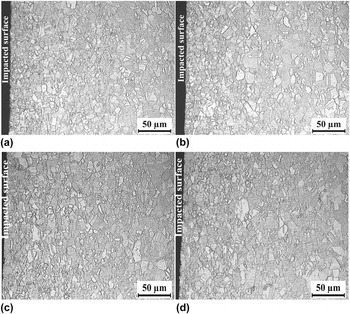
Figures 1(a) and 1(b) present the optical micrographs of the cross-sections of the Cu–4.5% Al samples processed by LNT SMAT and RT SMAT, respectively. It is clear that a gradient microstructure was obtained along the depth from the impacted top surface, as the grain size gradually increased from the treated surface to the central region. From Figs. 1(a) and 1(b), we can see fine-grained surface layers of about 20 μm and 15 μm in thickness, respectively. Generation of this gradient structure can reasonably be attributed to the gradient strain and strain rate that were induced into the sample during the SMAT process. Reference Tao, Wang, Tong, Sui, Lu and Lu12 As the depth increased, the strain and strain rates accordingly decreased to a certain level, and the top surface region underwent the highest strain and strain rate. The specific details of the microstructure evolution at different depths were characterized by Lu and Lu Reference Lu and Lu8 for numerous materials. Specifically, equiaxed dislocation cells and subgrain microstructures were formed by thermally activated processes under RT conditions. Reference Li, Tao and Lu4 By contrast, dislocation slip and tangle were significantly suppressed during the LNT process. In addition, the optical micrographs of the cross-sections of the Cu–2.2% Al samples processed by LNT SMAT and RT SMAT are presented in Figs. 1(c) and 1(d), respectively.
Optical micrographs of the cross-sections of Cu–Al samples: (a) Cu–4.5% Al processed by LNT SMAT; (b) Cu–4.5% Al processed by RT SMAT; (c) Cu–2.2% Al processed by LNT SMAT; and (d) Cu–2.2% Al processed by RT SMAT.

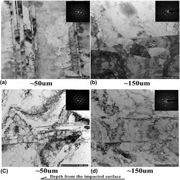
Figures 2(a) and 2(b) show cross-sectional TEM images at different depths from the impacted top surface in the LNT SMAT Cu–4.5% Al sample. At a depth of ∼50 μm [Fig. 2(a)], lots of parallel laminar structures are easily distinguishable. The inset corresponding selected area electron diffraction (SAED) pattern demonstrates a typical twin relationship between these lamellae. It is well-known that dislocation movement and deformation twinning are two fundamental deformation mechanisms for metallic materials. Furthermore, increasing strain rate or decreasing temperature will promote the formation of deformation twinning. Reference Darling, Tschopp, Roberts, Ligda and Kecskes14 As to the outer layer underwent the highest strain rate, plenty twinning was existed in Fig. 2(a), especially under LNT conditions. As the depth increased to ∼150 μm (adjacent to the strain-free matrix), high density dislocations can be obviously observed, and these are arrayed in tangles [Fig. 2(b)]. Figures 2(c) and 2(d) present cross-sectional TEM images of the RT SMAT Cu–4.5% Al sample at a depth of ∼50 and ∼150 μm, respectively. Clearly, plenty twin lamellae were generated at the depth of ∼50 μm. However, a less twin lamellar spacing can be seen in the LNT SMAT Cu–4.5% Al sample compared with the RT SMAT Cu–4.5% Al sample. With the depth increased to ∼150 μm, high density dislocations can also be observed.
Cross-sectional TEM images of Cu–4.5% Al samples at different depths from the impacted surface (from 50 up to 150 μm, as indicated): (a–b) LNT SMAT processed and (c–d) RT SMAT processed. Insets are the corresponding SAED patterns.

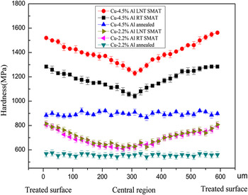
Figure 3 shows the microhardness variation along the depth from the impacted surface to the central region. After the SMAT process, it can be clearly observed that the hardness increased by a higher degree compared to the annealed sample. Moreover, the local hardness reached the highest value at the top surface region and decreased as the depth increased at a certain distance. For the LNT and RT SMAT Cu–4.5 % Al samples, the local hardness of the top surface layer reached maximum values of 1.52 and 1.28 GPa, respectively. As the depth increased to the central area, the hardness values decreased to 1.23 and 1.04 GPa, respectively.
Microhardness variation along the depth from the treated surface to the central region of the SMAT processed and the annealed Cu–Al alloy specimens.

For comparison, an annealed Cu–4.5% Al specimen was also tested in this work. Its local hardness was distributed more homogeneously, and the average local hardness across the cross-sectional region was about 897 MPa. The local hardness at the top surface layers of the LNT and RT SMAT samples was approximately 1.7 and 1.4 times more than that of the initial annealed sample. During the SMAT process, gradient-decreased plastic strain and strain rates were obtained from the impacted surface layer to the central matrix. Reference Wang, Tao, Liu, Lu and Lu16 As a result, a gradient microstructure was formed along the treated surface. The grains were refined to the minimum scale at the top surface layer, which can explain the dramatically increased local hardness in this region. Reference Lu and Lu8 Therefore, we conclude that the nonhomogeneity of the microhardness can be ascribed to the gradient microstructure. Reference Waltz, Retraint, Roos and Olier18 It is also interesting to observe that the local hardness of the central region of the SMAT specimens was much greater than that of the annealed sample, which can be explained by the high work hardening effect. Reference Waltz, Retraint, Roos, Olier and Lu19
The microhardness variations of the Cu–2.2% Al samples are also included in Fig. 3. The hardness, by contrast, increased to a high level after the SMAT process. However, the curve of the LNT SMAT sample is not obviously increased compared to the curve for the RT process, as described in curves D and E.
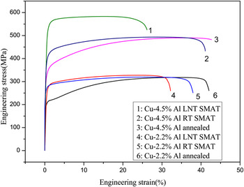
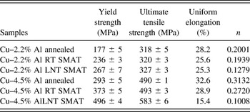
Figure 4 shows the tensile engineering stress–strain curves of Cu–2.2 % Al and Cu–4.5% Al samples treated by LNT and RT SMAT, respectively. The curves of the annealed samples are also given in Fig. 4. This demonstrates that the yield strength was significantly improved after the SMAT process, where it sustained higher ductility. The RT and LNT SMAT Cu–4.5% Al samples exhibited yield strengths of ∼373 and ∼496 MPa, which increased about 27 and 69% compared to the annealed specimen (∼293 MPa), respectively. In addition, the ultimate tensile strength reached ∼493 and ∼583 MPa, respectively. Correspondingly, the uniform elongation decreased to 28.9 and 15.4%, which is still acceptable compared with traditional SPD methods. In terms of the Cu–2.2% Al alloys, the yield strengths of the annealed, RT SMAT, and LNT SMAT samples were about ∼177, ∼236, and ∼267 MPa, respectively. The uniform elongation of the SMAT samples for the RT and LNT routes was slightly reduced to 25.6 and 25.3% compared to 28.2% for the annealed sample, respectively. The specific details are listed in Table I.
Uniaxial tensile engineering stress–strain curves of the SMAT processed and untreated Cu–Al alloy specimens.

Yield strength, ultimate tensile strength, uniform elongation, and work hardening exponent (n) of the SMAT processed and the annealed Cu–Al alloys.

Systematic analysis of the tensile data revealed that the Cu–4.5% Al alloys exhibited much better tensile properties than Cu–2.2% Al, regardless of whether the sample was processed by RT SMAT, or LNT SMAT or annealed, which indicates that SFE plays a significant role in improving the mechanical properties of Cu–Al alloys. Reference Cai, Long, Wen, Gong, Li, Tao and Zhu20 Decreasing SFE changes the dominant plastic deformation from dislocation slip to mechanical twinning, Reference Zhao, Horita, Langdon and Zhu21,Reference Zhang, Duan, An, Wu, Yang and Zhang22 and the grain refinement mechanism is accordingly transformed from dislocation subdivision to twin fragmentation. As can be seen from Figs. 2(a) and 2(c), high density deformation twins are generated at a depth of ∼50 μm. Improving mechanical twinning is a more effective approach for subdividing the original grains and optimizing the microstructure. Based on the well-established Hall–Petch relationship, decreasing grain size significantly enhances tensile properties. In addition, the contribution of solution hardening can be neglected; for this, the Al element was utilized to decrease the SFE. Reference Shen and Koch23
For samples with the same SFE, the RT SMAT and LNT SMAT samples exhibited a higher yield strength compared to the annealed specimen, especially in the Cu–4.5% Al alloy system. The improved yield strength can be attributed to the fine-grained surface layers on both sides, which were produced via the SMAT process. Reference Lu and Lu8 The experiments carried out by Lu et al. Reference Guo, Wang and Lu24 demonstrated that the yield strength of the impacted top surface layer (20 μm in thickness) was as high as 470 MPa, much higher than that of the coarse-grained Cu matrix. That is, the high yield strength of the fine-grained outer layers can enhance the apparent yield strength of the global sample. Moreover, intrinsic synergetic strengthening is generated due to the mechanical incompatibility between the fine-grained surface layer and the coarse-grained matrix. Reference Wu, Jiang, Chen, Zhang, Yuan and Zhu25 To be specific, during uniaxial tensile tests, plastic deformation first occurs at the central region, while the surface areas are still in an elastic condition. Reference Tian, Dai, Villegas, Shaw, Lian, Klarstrom and Ortiz26 As a result, the plastically deformed central region is restricted by the two elastically deformed surface layers. The mismatch between these plastic and elastic layers results in a biaxial stress state, Reference Wu, Jiang, Chen, Zhang, Yuan and Zhu25 and such two-dimensional stress states will activate more slip systems to increase dislocation accumulation and mutual intersection at the coarse-grained layer. Consequently, extra strengthening is produced due to the mechanical incompatibility of the different layers.
In addition, for the Cu–4.5% Al samples, the LNT SMAT sample was superior to the RT sample. In contrast with the RT sample, the yield strength and ultimate tensile strength of the LNT SMAT sample increased by about 33.0 and 18.2%, respectively. The reasons for this can be interpreted as follows: it is difficult to avoid a substantial temperature increment during the RT SMAT process; this results from the repeated impaction of the material surface with the steel balls and also the frictional heating effects. Reference Darling, Tschopp, Roberts, Ligda and Kecskes14 As a result, noticeable dynamic recovery and recrystallization were unavoidably induced into the sample substrate. Reference Li, Umemoto, Todaka and Tsuchiya27 For the samples processed under the LNT conditions, dislocations climbed and cross-slip were dramatically suppressed, which caused the dislocation density to increase to a higher degree. Reference Wang and Ma28 So, this can reasonably explain the superior tensile strength processed at LNT as opposed to RT.
Furthermore, due to the outer layers underwent the highest strain and strain rates, deformation twinning was generated in this region with decreasing deformation temperature under the LNT conditions. Reference Darling, Tschopp, Roberts, Ligda and Kecskes14 Therefore, the production of deformation twinning is a more effective approach for refining microstructure. Correspondingly, the dominant plastic deformation mechanism is transformed from dislocation slip at RT to twinning bands at LNT. For the Cu–2.2% Al samples, the tensile properties of the LNT SMAT sample were not significantly improved compared to those of the RT sample, as depicted in curves 4 and 5. However, previous studies Reference Subramanya Sarma, Wang, Jian, Kauffmann, Conrad, Freudenberger and Zhu29,Reference Qu, An, Yang, Huang, Yang, Zang, Wang, Wu and Zhang30 have shown that low SFE Cu–Al alloys are not sensitive to external conditions (strain rate and temperature) compared to medium SFE Cu–Al alloys. Such a conclusion is not consistent with our experimental results. For the low SFE Cu–4.5% Al alloy, the tensile properties dramatically improved with decreasing temperature under the LNT conditions. But for the medium Cu–2.2% Al alloy, the tensile properties were only slightly affected by decreased temperature. This inconsistency needs to be further studied to better understand this issue.
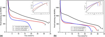
As for the decreased uniform elongation after the SMAT process, it is reasonable to attribute this to the inability to preserve a sufficient work hardening rate (Θ). As a result, the lower work hardening rate could not restrain the gathering of large grains in local areas. Reference Koch7 Figures 5(a) and 5(b) depict the work hardening rate against the true strain for the Cu–4.5% Al and Cu–2.2% Al samples, respectively. The insets are the corresponding flow stress–strain curves. As we can see, the work hardening rate decreased after the SMAT process, and the curves of the LNT SMAT samples are located at the lowest place. In addition, work hardening exponent (n) for all specimens is included in Table I.
Work hardening rate (Θ) against the true strain of (a) Cu–4.5% Al samples and (b) Cu–2.2% Al samples. Insets are the corresponding flow stress–strain curves.

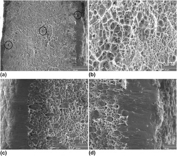
Figure 6(a) shows the fracture surface of the LNT SMAT Cu–4.5% Al sample after the tensile tests. Figures 6(b)–6(d) show high-magnification SEM micrographs of the selected areas 1, 2, and 3 in Fig. 6(a), respectively. As can be seen from Figs. 6(c) and 6(d), two significant failure patterns are easily distinguishable. In detail, there is an obvious flat fracture region about 20 μm in thickness at the outer surface, which could be characterized by a brittle failure pattern. With the depth increased, we can observe a few dimples that exist in the flat surface region. Figure 6(b) shows the fracture morphology of the central region, which exhibits a heavily dimpled and cone-like structure, and can be described as a ductile failure. Therefore, we can associate the brittle-ductile fracture with the fine-grained surface layer and impacted central region.
SEM micrographs of the fracture surface: (a) LNT SMAT processed Cu–4.5% Al sample and (b–d) high-magnification SEM micrographs of the selected areas as indicated in (a).

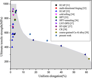
Figure 7 shows the variation of ultimate tensile strength with the uniform elongation of the SMAT samples for the Cu–4.5% Al alloy. In addition, literature data about Cu–Al alloys synthesized by other SPD methods Reference Qu, An, Yang, Huang, Yang, Zang, Wang, Wu and Zhang30–Reference Subramanya Sarma, Sivaprasad, Sturm and Heilmaier37 are also included. Careful analysis of these data reveals that the ultimate tensile strength was elevated to a high level through the SPD methods, but the ductility was dramatically decreased to a few percent. The brittleness of SPD processed materials usually limits their application fields. This novel SMAT method could improve the tensile strength to a greater level while maintaining comparable ductility, thus showing a simultaneous improvement in ultimate tensile strength and ductility. Furthermore, the LNT SMAT is a low-cost process with high productivity. Integrating these advantages has contributed to the wide use of this new technique in industrial applications.
The superior strength–ductility behavior of the Cu–Al alloys studied in the present work as compared to other Cu–Al alloys processed by various traditional SPD methods.

IV. CONCLUSIONS
In the present study, it has been demonstrated that the yield strength and ultimate tensile strength of the LNT SMAT Cu–4.5% Al sample improved to ∼496 and ∼583 MPa, respectively. Meanwhile, this process conserved an acceptable uniform elongation of 15.4%. The repeated treatment of the sample surface produced a gradient microstructure, and a fine-grained layer about 20 μm in thickness was generated at the top surface region. The increased yield strength can be ascribed to the fine-grained outer layers and the intrinsic synergetic strengthening effect. When the temperature was decreased under the LNT conditions, dislocation climb and cross-slip were dramatically suppressed, which can explain the higher tensile strength compared to that of the RT SMAT sample. Therefore, the LNT SMAT process is an effective approach to improving the mechanical properties of metallic materials, and it can be applied to various types of metallic production.
ACKNOWLEDGMENT
The authors wish to acknowledge the assistance and support of the National Natural Science Foundation of China (Grant No. 50874056).