I. INTRODUCTION
In recent years, there has been a growing interest in wireless power transfer (WPT) that represents a promising technology for energizing low-power electronic devices [Reference Costanzo1–Reference Wu, Wang, Yerazunis and Teo9].
In this regard, particularly attractive is the use of WPT for recharging embedded devices, such as sensors for structural monitoring [Reference Salas, Focke, Herrmann and Lang10, Reference Dräger, Mayordomo and Schuster11] or implantable medical devices (IMD) [Reference Chen, Liu and See12–Reference Yilmaz and Dehollaini28]; in fact, these devices are difficult to access for the battery replacement or a direct connection to a power grid.
More specifically, in the case of medical implants, the limited lifetime of the battery determines the necessity of periodically replacing the device through surgery. For instance, the typical lifetime of a pulse generator, such as the ones adopted for cardiac or deep brain (DB) stimulation, is in the range of 2–5 years. The use of WPT combined with a rechargeable battery could extend the lifetime of these devices up to 20 years, with obvious advantages for their users. Additionally, wireless links with IMD are also crucial for data transfer.
According to these considerations, in the literature, several wireless links for either data or power transfer to medical implants have been proposed [Reference Chen, Liu and See12–Reference Yilmaz and Dehollaini28].
In particular, according to the rules of the RF spectrum management, which reserve the MedRadio (Medical Device Radiocommunications Service) band [29] for medical implants and wearable medical devices, most of the data links for medical devices that have been proposed up to now in the literature use compact printed implantable antennas operating in the MedRadio band or at higher frequencies [Reference Chen, Liu and See12–Reference Asili, Green, Seran and Topsakal15].
As per wireless links for power transfer to an IMD, the choice usually adopted consists in using links based on magnetic coupling. More recently, the use of resonant schemes has been proposed. These schemes are realized by adding appropriate compensating reactances to a purely inductive link and allow maximizing the achievable performance.
As per the operating frequency, most of the WPT links for IMDs, which have been proposed in the literature, operate at very low frequencies in the range from some kHz up to some MHz. The aim of this choice is to minimize losses due to electromagnetic energy absorption in human tissues and to maximize the efficiency of the link. However, this choice has the important drawback of imposing the use of two different wireless links for data and power transmission. Accordingly, in [Reference Monti, Arcuti and Tarricone30–Reference Monti, De Paolis and Tarricone32], the use of the MedRadio band for energizing a medical device for cardiac [Reference Monti, Arcuti and Tarricone30] and DB stimulation [Reference Monti, De Paolis and Tarricone31, Reference Monti, De Paolis and Tarricone32] has been investigated.
In particular, the WPT links presented in [Reference Monti, Arcuti and Tarricone30–Reference Monti, De Paolis and Tarricone32] adopt a resonant inductive scheme consisting of two magnetically coupled resonators optimized for energizing a pulse generator implanted in the chest.
In this paper, the results presented in [Reference Monti, De Paolis and Tarricone31, Reference Monti, De Paolis and Tarricone32] have been extended by solving the problem of the integration of the receiving resonator into the medical device, i.e. a pulse generator such the ones adopted for cardiac stimulation and DB stimulation. In particular, the solution here presented consists in integrating the resonator in the silicone header of a pulse generator implanted in the chest. The results obtained from experimental tests for an optimized implementation of the link presented in [Reference Monti, De Paolis and Tarricone31, Reference Monti, De Paolis and Tarricone32] demonstrate an RF-to-RF power transfer efficiency of about 51%. Additionally, the feasibility of using the proposed link for recharging the lithium-ion (Li-ion) battery of the medical device is discussed. It is demonstrated that the link presented in this paper is able to recharge a battery with a capacity in the range from 207 to 399 mAh in a reasonable time (4–6 h) and in compliance with the 2 W/kg limit imposed by safety regulations for the specific absorption rate (SAR) averaged on a mass of 10 g.
The paper is organized as follows. In Section II, the proposed WPT link is briefly described and full-wave simulation results are given; in Section III, the performance achieved by measurements are reported. In Section IV, the results obtained by full-wave simulations for investigating the sensitivity of the performance on possible variations of the link parameters are illustrated. In Section V, the feasibility of using the proposed WPT link for recharging a pacemaker in compliance with safety regulations is discussed and verified through full-wave simulations. Finally, some conclusions are drawn in Section VI.
II. GEOMETRY AND FULL-WAVE SIMULATION RESULTS
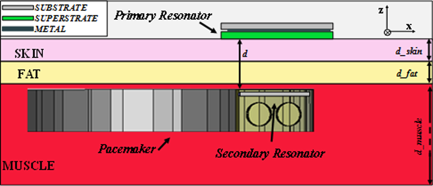
The proposed link is realized by two magnetically coupled resonators, each one consisting of a distributed inductance loaded by a lumped capacitor. The configuration assumed for the resonators is depicted in Fig. 1: the primary resonator (i.e. the external resonator) is in direct contact with the skin, whereas the secondary resonator is implanted at a depth of 5 mm (d) in a layer of muscle and below a layer of skin and fat.
Configuration adopted for the WPT link: the primary resonator operates in direct contact with the skin, whereas the secondary resonator is embedded into the silicone header of a pacemaker implanted in a layer of muscle and below a layer of skin and fat. The two resonators are at a distance d = 5 mm (the secondary resonator is implanted into the muscle layer under a 2 mm layer of skin and a 2 mm layer of fat).

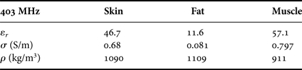
Table 1 summarizes the values assumed for the electromagnetic parameters of human tissues; the IT'IS Foundation database [33] was taken as a reference.
Parameters adopted in full-wave simulations for human tissues.

As per the geometry of each resonator, it is a modified version of the solution presented in [Reference Monti, De Paolis and Tarricone31, Reference Monti, De Paolis and Tarricone32]. In fact, in previous works, the authors investigated different geometries for the implementation of the two coupled resonators. In particular, in [Reference Monti, Tarricone and Trane18], a preliminary study regarding the possibility of energizing a medical implant by using a wireless link operating at 434 MHz has been performed by using two segmented spiral loops. The realized geometries were rather cumbersome: the area occupied by the receiver was about 27 mm × 27 mm, while that occupied by the transmitter was about 60 mm × 60 mm. As per the efficiency, at the operating frequency, the maximum achieved was of about 5%.
In [Reference Monti, Arcuti and Tarricone30], a progress has been made in terms of miniaturization by realizing the same performance with two very compact resonators. In more detail, the link proposed in [Reference Monti, Arcuti and Tarricone30] is based on the use of a split ring resonator of dimensions 15 mm × 15 mm as receiver and a spiral loop with dimensions 30 mm × 30 mm as transmitter. The maximum realized for the efficiency at 403 MHz is the same achieved in [Reference Monti, Tarricone and Trane18], i.e. 5%.
An improvement in terms of performance has been achieved in [Reference Monti, De Paolis and Tarricone31, Reference Monti, De Paolis and Tarricone32], where a maximum of about 15% has been obtained for the efficiency of the link. This result was obtained by using concentric loops for realizing the distributed inductance; the dimensions of the resonators are comparable to those of the resonators presented in [Reference Monti, Arcuti and Tarricone30].
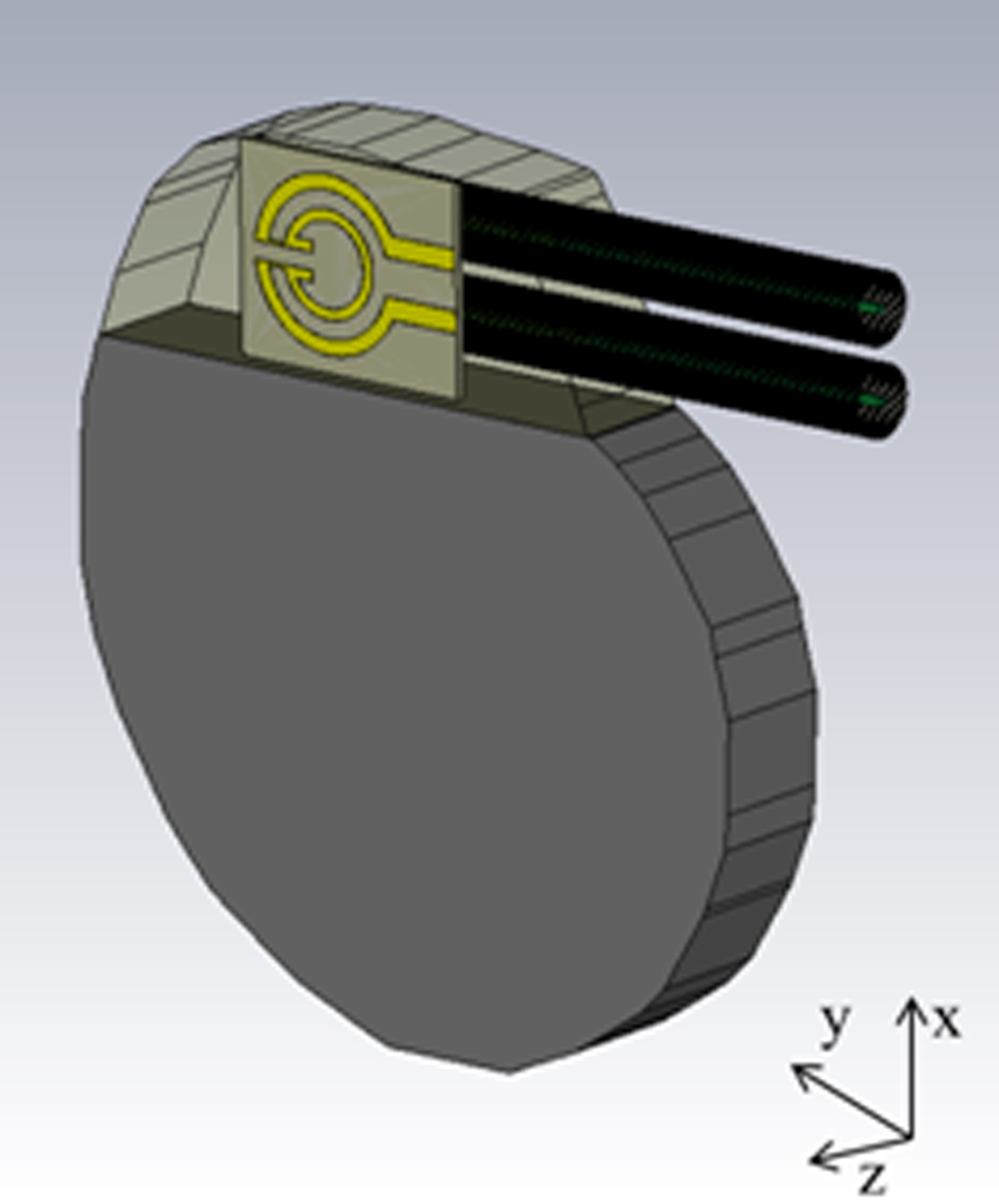
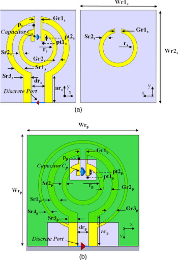
Accordingly, the geometry of the resonators presented in [Reference Monti, De Paolis and Tarricone32] has been assumed as starting point of the present investigation with the goal of maximizing the performance when the secondary resonator is integrated into the silicone header of a pacemaker. In more detail, the geometries proposed in [Reference Monti, De Paolis and Tarricone31, Reference Monti, De Paolis and Tarricone32] have been modified in order to: (1) make the dimensions of the secondary resonator compatible with the integration into the silicone header of a pacemaker, (2) maximize the efficiency of the link when the secondary resonator is in the silicone header of a pacemaker (see Fig. 2). For the design of the pacemaker, the T60 DR by Vitatron has been taken as a reference. Both resonators were designed on an Arlon DiClad 880 substrate (ε r = 2.17, tanδ = 0.0009) with a thickness of 0.508 mm. The geometry of the secondary resonator is the same adopted in [Reference Monti, De Paolis and Tarricone31, Reference Monti, De Paolis and Tarricone32] with optimized dimensions of the design's parameters (see Fig. 3(a)). With respect to the solution proposed in [Reference Monti, De Paolis and Tarricone31, Reference Monti, De Paolis and Tarricone32], the one presented in this paper does not use a superstrate. As per the primary resonator, the geometry is illustrated in Fig. 3(b). The distributed inductance is realized on the front face of the Arlon substrate, and, similarly to the design presented in [Reference Monti, De Paolis and Tarricone31, Reference Monti, De Paolis and Tarricone32], a high electric permittivity superstrate (i.e. the Arlon AR1000 substrate, ε r = 9.7, and tanδ = 0.003, thickness = 0.610 mm) is used for improving the RF-to-RF power transfer efficiency.
Receiving resonator integrated into the silicone header of a pacemaker. For the dimensions of the pacemaker, the Vitatron T60 DR has been taken as a reference.

(a) Geometry of the secondary resonator. The distributed inductance is realized on the front and back face of the Arlon substrate. (b) Geometry of the primary resonator. In this case, the distributed inductance is realized on the front face of the substrate and a high electric permittivity superstrate is used.

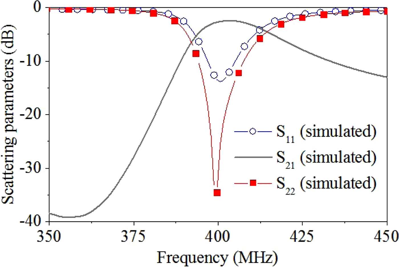
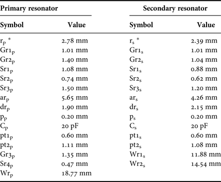
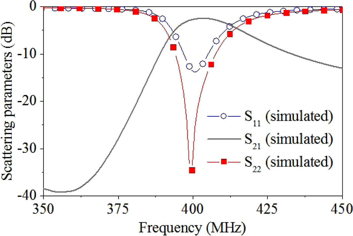
The optimization process of the two resonators was carried out by using the full-wave simulator CST Microwave Studio. In more detail, first of all, we coarsely optimized the radii of the loops and the value of the lumped capacitors in order to obtain a frequency of resonance at about 403 MHz. Then, the value of the lumped capacitor was fixed to the nearest value among the available discrete ones. Finally, a fine optimization of all the parameters (widths of the loops, gaps between coplanar loops, radii of the loops) was performed with the goals of maximizing the level of matching of both the resonators, exactly tuning the frequency of resonance at 403 MHz and maximizing the efficiency at 403 MHz. The final dimensions of the optimized geometries are given in Table 2. The corresponding scattering parameters calculated by using the full-wave simulator CST Microwave Studio are given in Fig. 4; a reference impedance of 50 Ω has been assumed at both ports.
Results obtained from full-wave simulations for the scattering parameters of the proposed WPT link (the normalization impedance is 50 Ω).
Dimensions of the resonators.
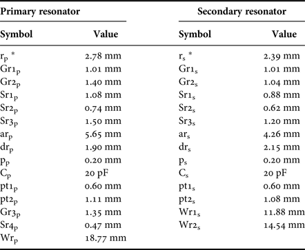
* Subscript letter p or s denotes the primary and the secondary resonator, respectively.
III. EXPERIMENTAL RESULTS
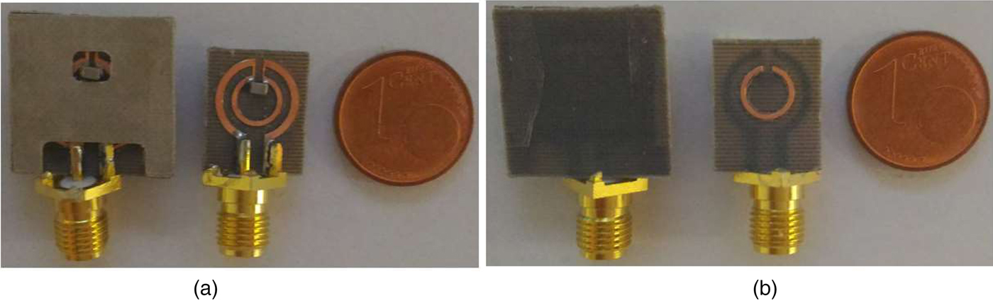
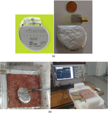
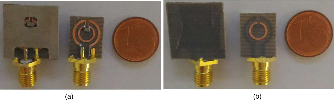
The photographs of the fabricated resonators are given in Fig. 5. In order to verify the full-wave simulation results reported in Fig. 4, a prototype simulating the integration of the secondary resonator in the silicone header of a Vitatron T60 DR pacemaker has been realized. A photograph is given in Fig. 6(a) where the realized device is compared with the T60 DR. In order to simulate the titanium case of the pacemaker, an aluminum foil has been used and shaped according to the dimensions of the T60 DR.
Photographs of the fabricated resonators. (a) Front view: primary resonator on the left and secondary resonator on the right. (b) Back view: primary resonator on the left and secondary resonator on the right.
Photographs of the setup adopted for measurements. (a) Prototype simulating the integration into the silicone header of a pacemaker. (b) Setup adopted for measuring the scattering parameters of the link. A minced pork has been used for simulating the presence of human tissues.

The experimental setup adopted for measuring the scattering parameters of the link is shown in Fig. 6(b); in order to mimic the presence of human tissues, a minced pork has been used. In fact, in a previous work [Reference Monti, Arcuti and Tarricone30], it has been demonstrated that in the frequency range of interest, minced pork has electromagnetic parameters very close to the ones of an effectively homogeneous medium equivalent to the stack of three human tissues of interest (i.e. skin, fat, and muscle).
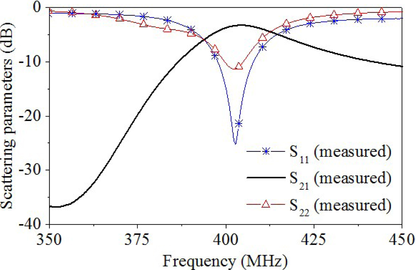
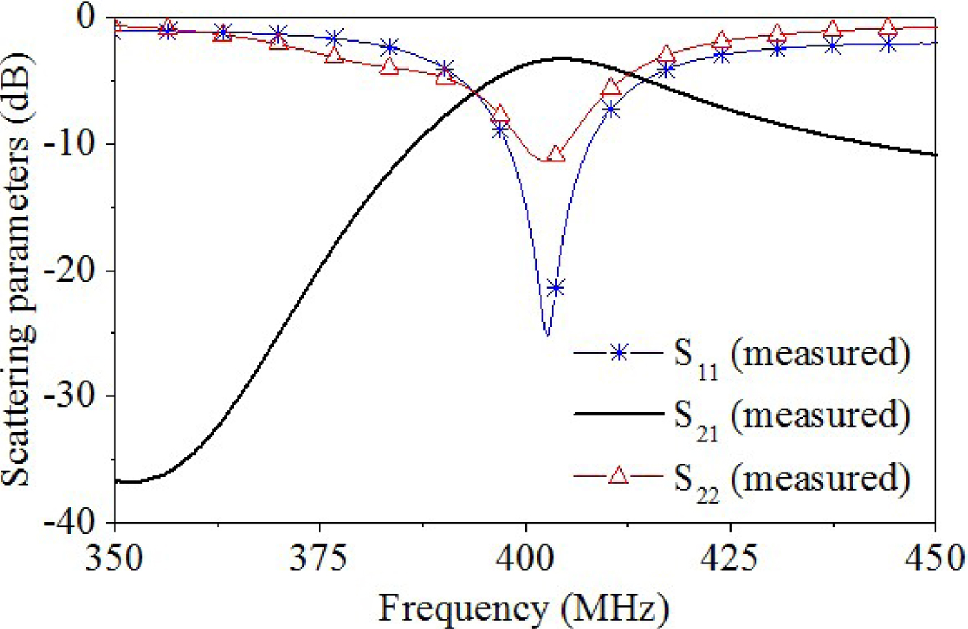
The scattering parameters measured by using the setup illustrated in Fig. 6(b) are given in Fig. 7. By comparing Fig. 4 with Fig. 7, it is evident that a very good agreement has been obtained between numerical and experimental data.
Results obtained from measurements for the scattering parameters of the proposed WPT link (the normalization impedance is 50 Ω, i.e. R G = R L = 50 Ω).
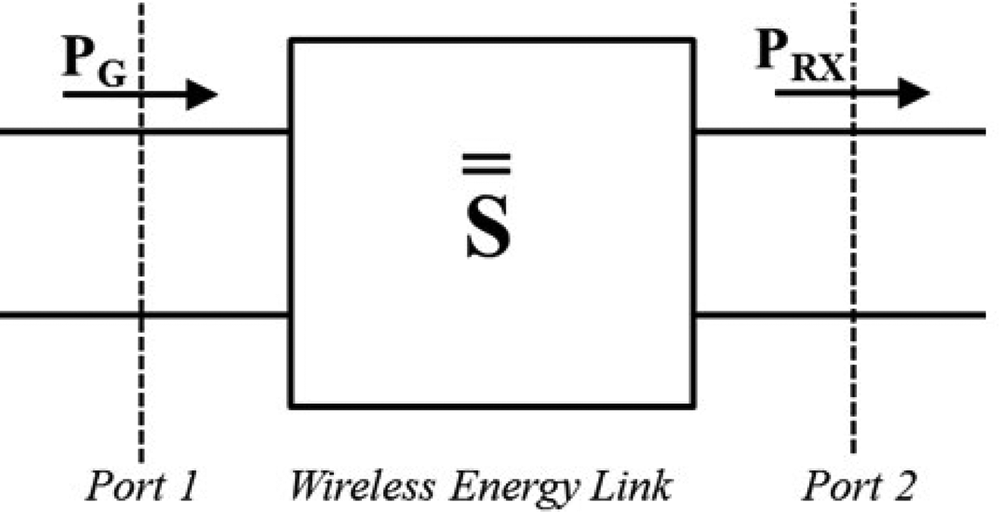
With regard to the use of the WPT link to wirelessly connect a generator with impedance R G to a load R L (see Fig. 8), the following definition is used for the RF-to-RF power transfer efficiency (η RF−RF ):
 $$\eta _{RF - RF}= \displaystyle{{{\rm power}\;{\rm delivered}\;{\rm to\;} \;{\rm the\;} \;{\rm load\;} \;R_L{\rm \;}} \over {{\rm available}\;{\rm power}\;{\rm from\;} \;{\rm the}\;{\rm source}}}= \displaystyle{{P_{RX}} \over {P_G}}= \left \vert {S_{{\rm 21}}} \right \vert ^{\rm 2}.$$
Schematic representation of the wireless energy link.

According to (1), the η RF−RF is the transducer gain of the two-port network as defined in Chapter 4 of [Reference Collin34] and, as explained in [Reference Collin34] (see equation (4.97) of [Reference Collin34]), it can be expressed as in (1) by using the parameter S 21 of the generalized scattering matrix of the two port network calculated by using R G as normalization impedance at port 1 and R L as normalization impedance at port 2 (see Fig. 8).
It is worth observing that the expression of the η RF−RF given in (1) is different from the one adopted in [Reference Monti, Arcuti and Tarricone30–Reference Monti, De Paolis and Tarricone32]; however, this definition is the one commonly used in the context of WPT [Reference Inagaki35] and simplifies the comparison with previously published results.
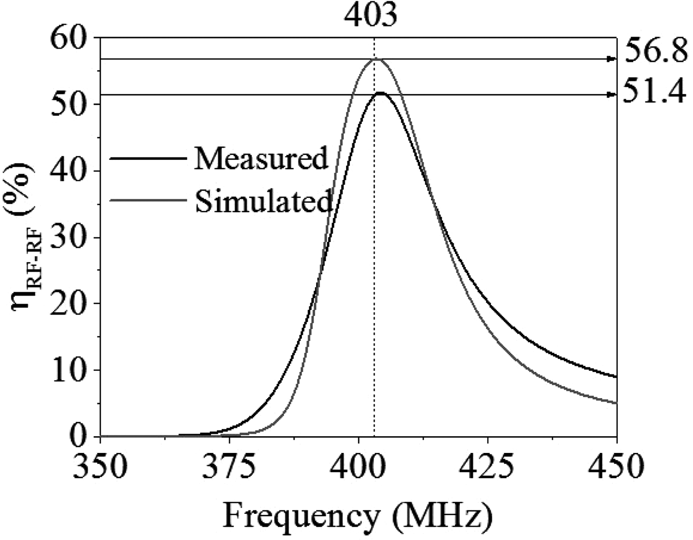
By using (1), the η RF−RF corresponding to measurements is given in Fig. 9 and compared with simulation results. From Fig. 9, it is evident that at the operating frequency of the proposed link, i.e. at 403 MHz, the measured value of the η RF−RF is 51.4%, while it is 56.8% from full-wave simulations.
RF-to-RF efficiency for R G = R L = 50 Ω. Comparison between numerical and experimental data.

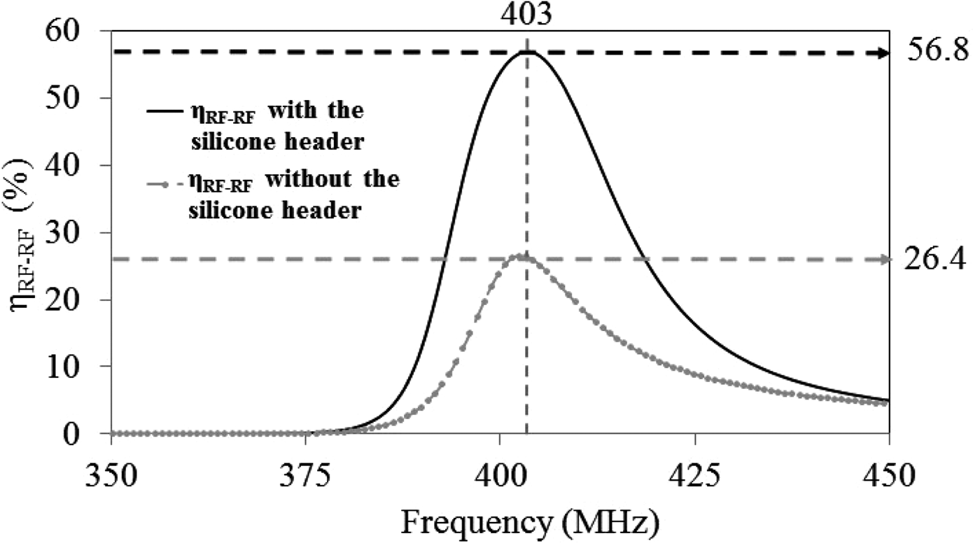
It is worth observing that these values are decisively higher than the ones achieved in [Reference Monti, De Paolis and Tarricone31, Reference Monti, De Paolis and Tarricone32]; in fact, by using (1) the efficiency of the link presented in [Reference Monti, De Paolis and Tarricone31, Reference Monti, De Paolis and Tarricone32] is of about 15.27%. This improvement of the performance is primarily due to the integration of the receiver in the silicone header of the pacemaker. In fact, according to full-wave simulation results, the embedding of the receiver in a silicone case allows improving the robustness of the performance of the link with respect to the surrounding environment (i.e. with respect to the human tissues). This consideration is highlighted in Fig. 10, where the η RF−RF of the link with and without the silicone header is reported.
RF-to-RF efficiency for R G = R L = 50 Ω. Results obtained from full-wave simulations of the proposed link with and without the silicone header.

IV. SENSITIVITY ANALYSIS
As explained in Section II, the link proposed in this paper has been optimized for operation at a depth of 5 mm. In fact, according to information received by cardiac surgeons, pacemakers are usually implanted under the skin at about a depth of 5 mm. However, due to the variability of the thickness of the human tissues and to patient's movement during the recharge process, small variations of the position of the medical implant with respect to the one that is expected are possible.
Accordingly, it is worth investigating the effect on the performance of the proposed power link of:
-
• possible variations of the thickness of the human tissues of interest, and then of the implantation depth;
-
• a misalignment between the two resonators.
In this section, the results obtained by full-wave simulations are reported and discussed.
A) Effect on the performance of the implantation depth
First of all simulations have been performed in order to investigate how the implantation depth of the medical implant affects the performance of the link. Different configurations have been investigated assuming a possible variation of one of the three human tissues of interest (see Fig. 1).
The analyzed cases are described in the following.
-
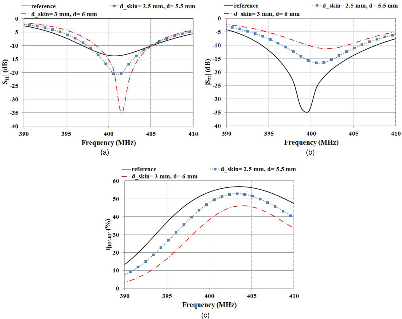
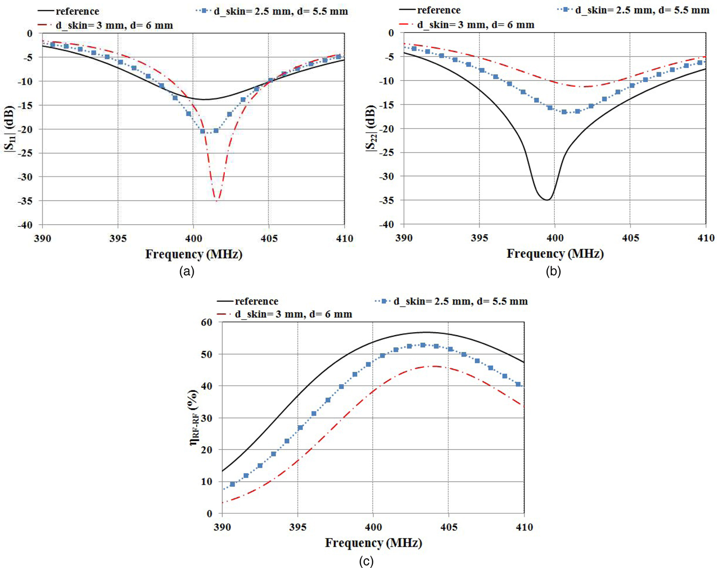
1. Variation of the thickness of the skin layer – A range of variability between 2 and 3 mm has been assumed, this corresponding to a range of variability of the implantation depth between 5 and 6 mm. The achieved results are given in Fig. 11; the efficiency calculated for an implantation depth of 6 mm is 47%.
-
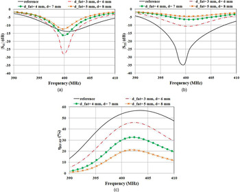
2. Variation of the thickness of the fat layer – A range of variability between 2 and 5 mm has been assumed, this corresponding to a range of variability of the implantation depth between 5 and 8 mm. The achieved results are given in Fig. 12; the efficiency calculated for an implantation depth of 8 mm (2 mm of skin, 5 mm of fat, 1 mm of muscle) is 21%. As evident from Fig. 12(b), the increase of the thickness of the fat layer leads to a consistent deterioration of the level of matching at the port of the receiving resonator.
-
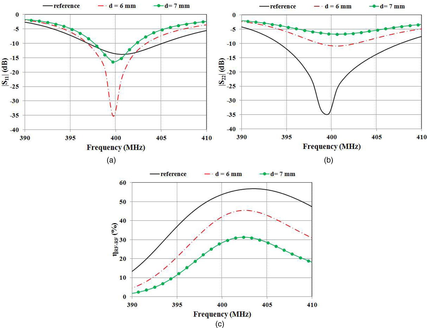
3. Variation of the implantation depth into the muscle layer – A range of variability between 1 and 3 mm has been assumed, this corresponding to a range of variability of the implantation depth between 5 and 7 mm. The achieved results are given in Fig. 13, the efficiency calculated for an implantation depth of 7 mm (2 mm of skin, 2 mm of fat, 3 mm of muscle) is 31%.
Results achieved by varying the thickness of the skin layer (d_skin) in the range of 2–3 mm, thus corresponding to an overall implantation depth (d) varying in the range of 5–6 mm.
Results achieved by varying the thickness of the fat layer (d_fat) in the range of 2–5 mm, thus corresponding to an overall implantation depth (d) varying in the range of 5–8 mm.

Results achieved by varying the implantation depth into the muscle layer in the range of 1–3 mm, thus corresponding to an overall implantation depth (d) varying in the range of 5–7 mm.
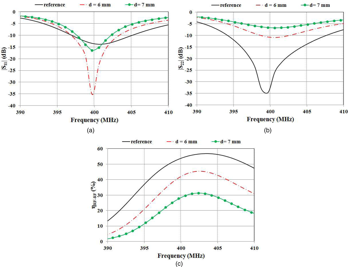
In Figs 11–13, the curve named ‘reference’ is the one corresponding to the link configured as in Fig. 1, i.e. with the secondary resonator aligned with the primary resonator and implanted at a depth of 5 mm (2 mm of skin, 2 mm of fat, 1 mm of muscle).
As expected, the variation of the thickness of the human tissues leads to a deterioration of the performance of the link.
It is worth noticing that the deterioration of the performance seems to be simply related to the deeper implantation depth, while it is not substantially affected by which of the three human tissues of interest has determined the increase of the implantation depth. This is evident from the comparison of Figs 11–13; in fact, from these figures, it can be seen that a nearly coincident performance has been calculated for the configurations corresponding to the same implantation depth (see for instance the dashed-dot red lines).
Additionally, from Figs 11–13, it can be noticed that the increase of the implantation depth leads to a consistent deterioration of the level of matching at the port of the receiving resonator and this seems to be the main cause of the deterioration of the performance.
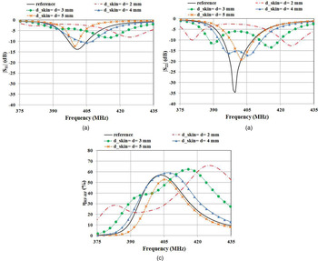
A further configuration which has been investigated is the one corresponding to the implantation of the medical device just under the skin; as a consequence, referring to Fig. 1, in this configuration d_skin is the implantation depth (d). The results achieved for a thickness of the skin layer in the range of 2–5 mm are given in Fig. 14. From this figure, it can be recognized that the link operates in an overcoupling regime for d_skin = 2 mm and d_skin = 3 mm.
Results achieved for the case where the medical device is implanted under the skin: d_skin coincides with the distance between the two resonators (d).

In resonant inductive links, the term ‘overcoupling’ is used to refer to an operation regime where the magnetic coupling coefficient is above a critical value and this determines the so-called ‘frequency splitting’ phenomenon. In more detail, when the link operates in an overcoupling regime, the efficiency does not exhibit an absolute maximum at the resonant frequency, but it exhibits two relative maxima at two separate frequencies, one above and one below the frequency of resonance (see the results given in Fig. 14(c) for d_skin = 2 mm and d_skin = 3 mm).
B) Effect on the performance of a misalignment
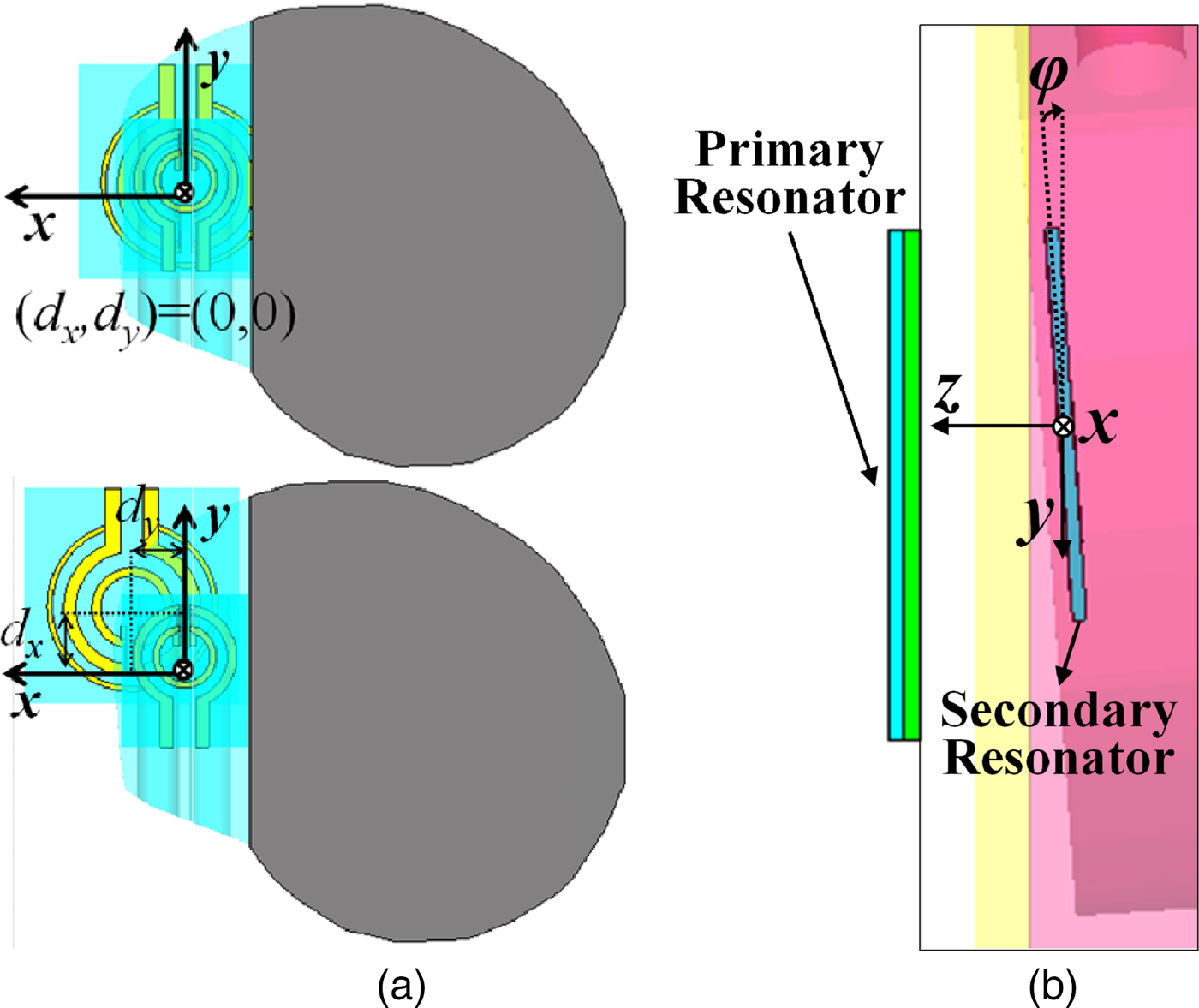
Another aspect that has been investigated is the effect on the performance of a misalignment between the two resonators.
Two are the main possible causes of a misalignment:
-
1. a shift of one of the two resonators in the xy-plane (see Fig. 15(a)),
-
2. a rotation of the receiving resonator (see Fig. 15(b)).
The case of misaligned resonators: (a) misalignment due to a shift on the xy plane; (b) misalignment due to a rotation of the receiver in the yz plane.
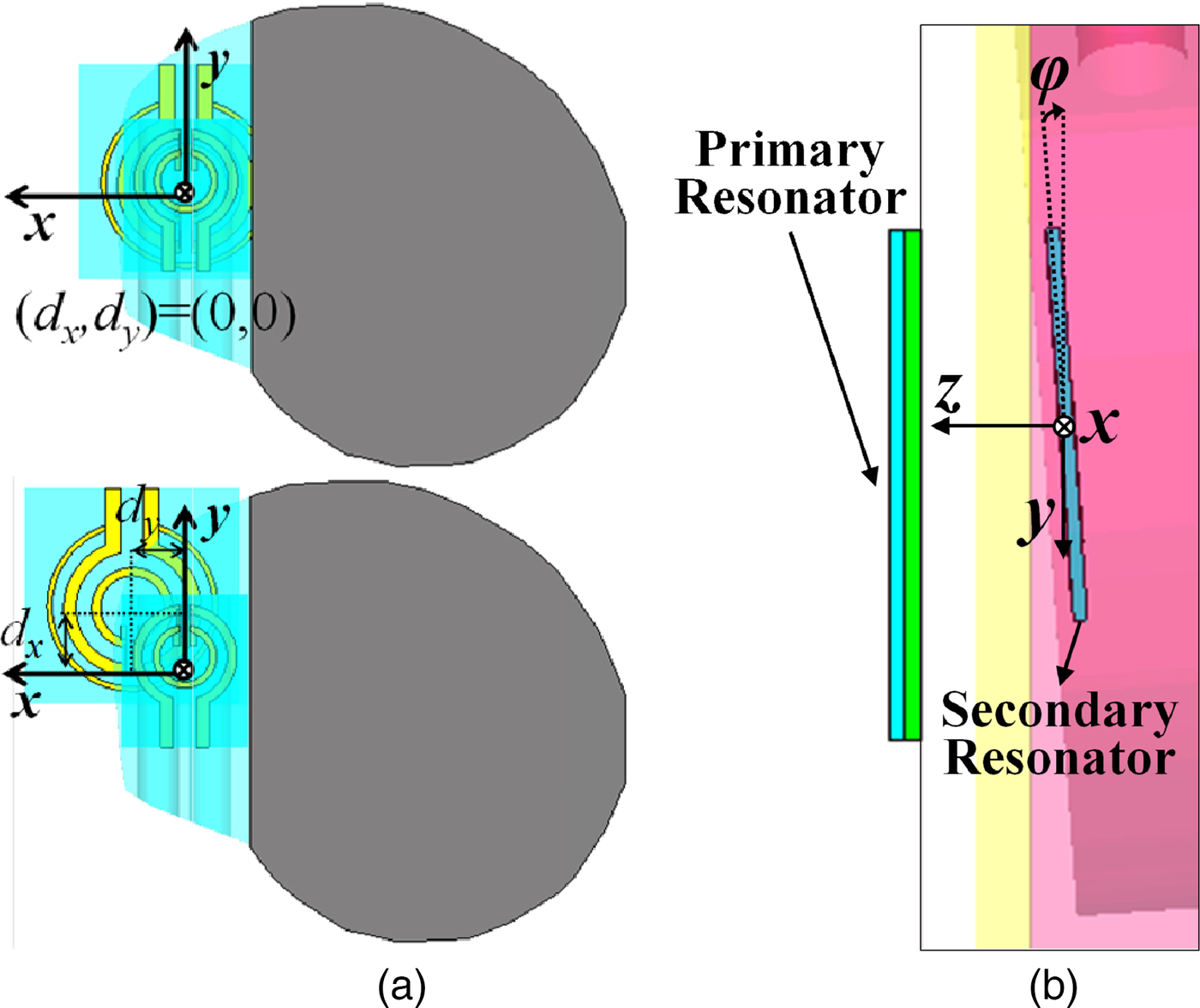
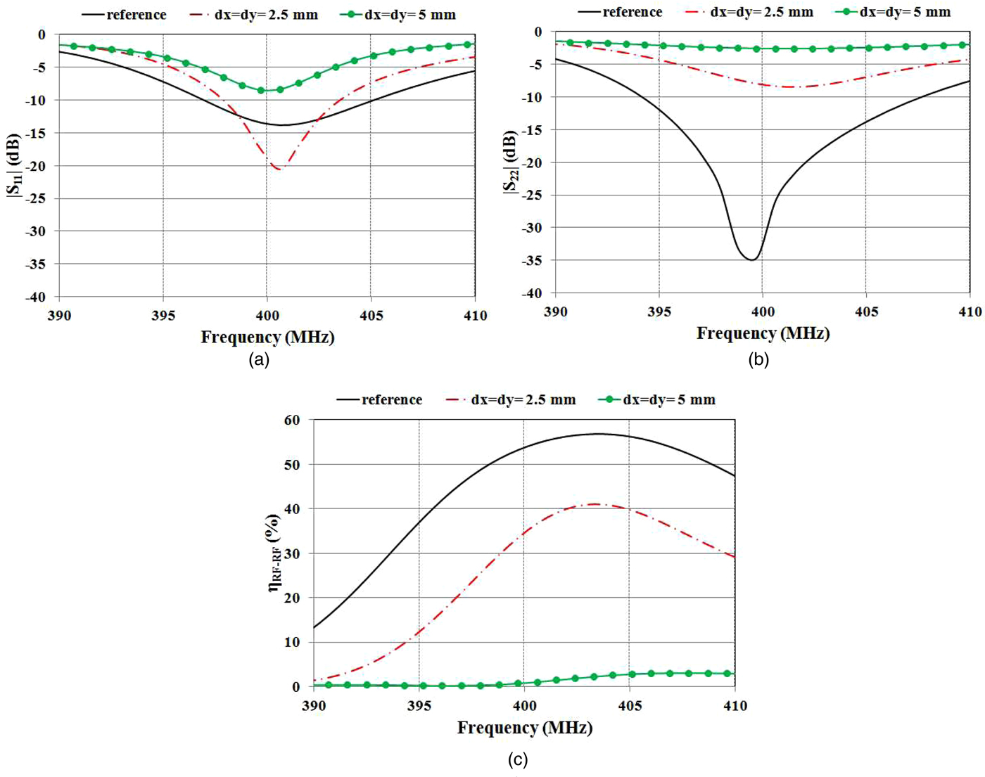
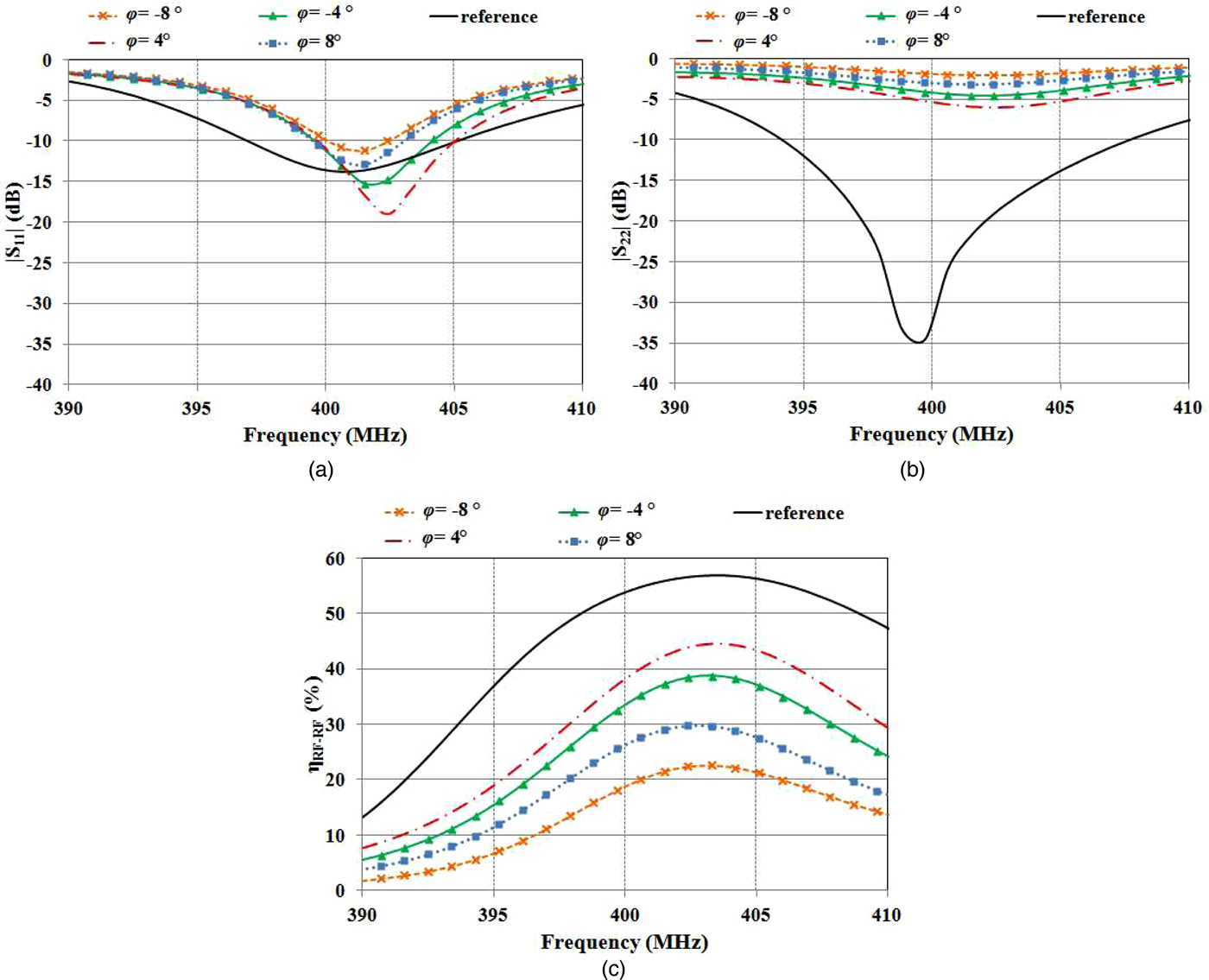
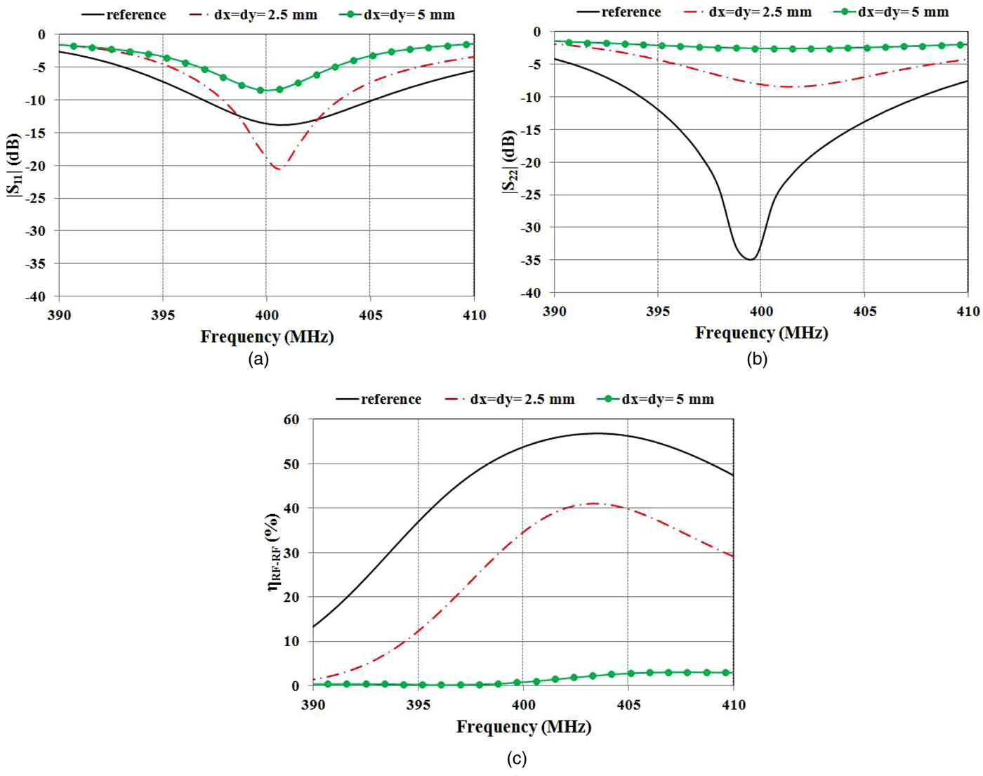
The results achieved by full-wave simulations are given in Figs 16 and 17. In this case, the curve named ‘reference’ also corresponds to the link configured as in Fig. 1.
Results achieved when the resonators are misaligned as illustrated in Fig. 15(a).
Results achieved when the resonators are misaligned as illustrated in Fig. 15(b).

As evident from Fig. 16, due to the small size of the two resonators, a shift of the primary resonator with respect to the optimum position on the xy plane leads to a very rapid deterioration of the performance. In fact, it can be easily verified that a shift of only 5 mm corresponds to the case of resonators almost completely misaligned. The efficiency calculated at 403 MHz for dx = dy = 5 mm is about 2.3%.
As per the case of a misalignment due to a rotation of the receiving resonator, the values that are reasonable to be considered are the ones reported in Fig. 17. As it can be seen, in the worst case, an efficiency of about 21% has been obtained at the operating frequency.
C) Discussion on results: how to improve the robustness of the performance
As expected, the results reported in this section confirm that the performance of the proposed link strongly depends on the relative position of the two resonators. According to the information received from cardiac surgeons, the assumption that the two resonators operate at a distance of approximately 5 mm is realistic and it can be reasonably assumed that this value hardly changes after implantation.
Conversely, misalignments due to a shift on the xy plane of the two resonators or to a rotation of the implanted device can occur due to movements of the implant bearer during charging.
Misalignments due to a shift on the xy-plane could be minimized by placing the primary resonator on a wearable elastic strap, which could help to keep the transmitting resonator in the right position even when the patient is moving. In this regard, we are also investigating the possibility of using an array of resonators realized on a separate substrate and placed on the back face of the primary resonator. These additional resonators have a focusing effect and allow to improve the robustness of the performance with respect to misalignments due both to shifts on the xy plane and to rotations.
However, although some precautions can be taken to minimize the situations of misalignment, since the problem is to align an external device with an implanted and not visible one, there is no guarantee that they will not occur. Accordingly, as suggested in [Reference Monti, Arcuti and Tarricone30], these problems should be monitored by using a control unit (CU) similar to the one already present in current pacemakers for monitoring the level of charge of the battery. In fact, in non-rechargeable pacemakers, there is a CU that emits an acoustic alarm when the level of charge of the battery is below a critical value. In wirelessly rechargeable pacemaker, the CU should emit an alert signal when the power delivered to the secondary resonator is below a threshold value, which could compromise the correct operation of the charging system.
Another problem to be taken into account is a possible shift of the frequency where the maximum of the power transfer efficiency occurs, this shift could be the consequence of a shift of the frequency of resonance of the secondary resonator, or, much more likely, it could be due to an overcoupling operating regime (see the results given in Fig. 14 and corresponding to the medical device implanted at depth smaller than 4 mm). This problem can be fixed by acting on the primary resonator. In particular, a possible solution could be to not use the primary resonator in direct contact with the skin.
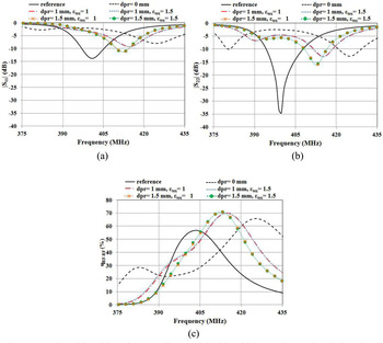
For instance, Fig. 18 shows the results obtained by using a textile material with a thickness dpr and a relative electric permittivity ε tex to separate the primary resonator from the skin. The results refer to the case where the receiver is implanted at a depth of 2 mm under the skin. Considering that common textile materials have a relative electric permittivity in the range of 1–1.6, two different cases have been analyzed ε tex = 1 and ε tex = 1.5. As per dpr, the best results have been obtained for dpr = 1 mm and dpr = 1.5 mm. From Fig. 18, it can be seen that by using a textile with a thickness of 1.5 mm, an efficiency higher than 50% has been obtained.
Results achieved by using a textile material with a thickness ‘dpr’ and a relative electric permittivity ε tex for separating the primary resonator from the skin.

With regard to problems related to the implantation depth of the secondary resonator, it is worth observing that it is expected that the implantation depth, smaller or greater than the one assumed in optimizing the link, does not change significantly during the various uses of the device. Accordingly, the check for these kind of problems should be performed only during the first uses.
V. HOW TO USE THE PROPOSED WPT LINK FOR A WIRELESS CHARGER OF A PULSE GENERATOR IMPLANTED IN THE CHEST: ACHIEVABLE PERFORMANCE AND COMPLIANCE WITH SAFETY REGULATIONS
The intended application for the proposed WPT link is the recharge of the battery of a pulse generator implanted in the chest. Pulse generators adopted for cardiac and DB stimulation use a small capacity Li-ion battery, the typical value of the capacity is in the range of 0.5–325 mAh.
Accordingly, in order to verify that it is feasible to use the proposed WPT link for recharging the target medical device, it is necessary to verify that it is feasible to use the link for recharging a small Li-ion battery in a reasonable charging time. In the following part of this section, the achievable performance and the compliance with safety regulations of a wireless charger using the proposed WPT link will be discussed.
A) Wireless charger: achievable performance
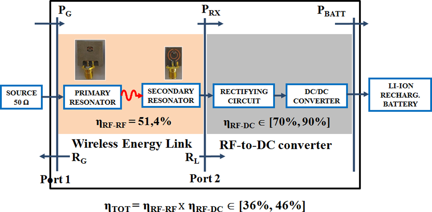
A schematic representation of a possible implementation of a charger using the proposed WPT link for recharging a small Li-ion battery is given in Fig. 19.
Schematic representation of a wireless battery charger.
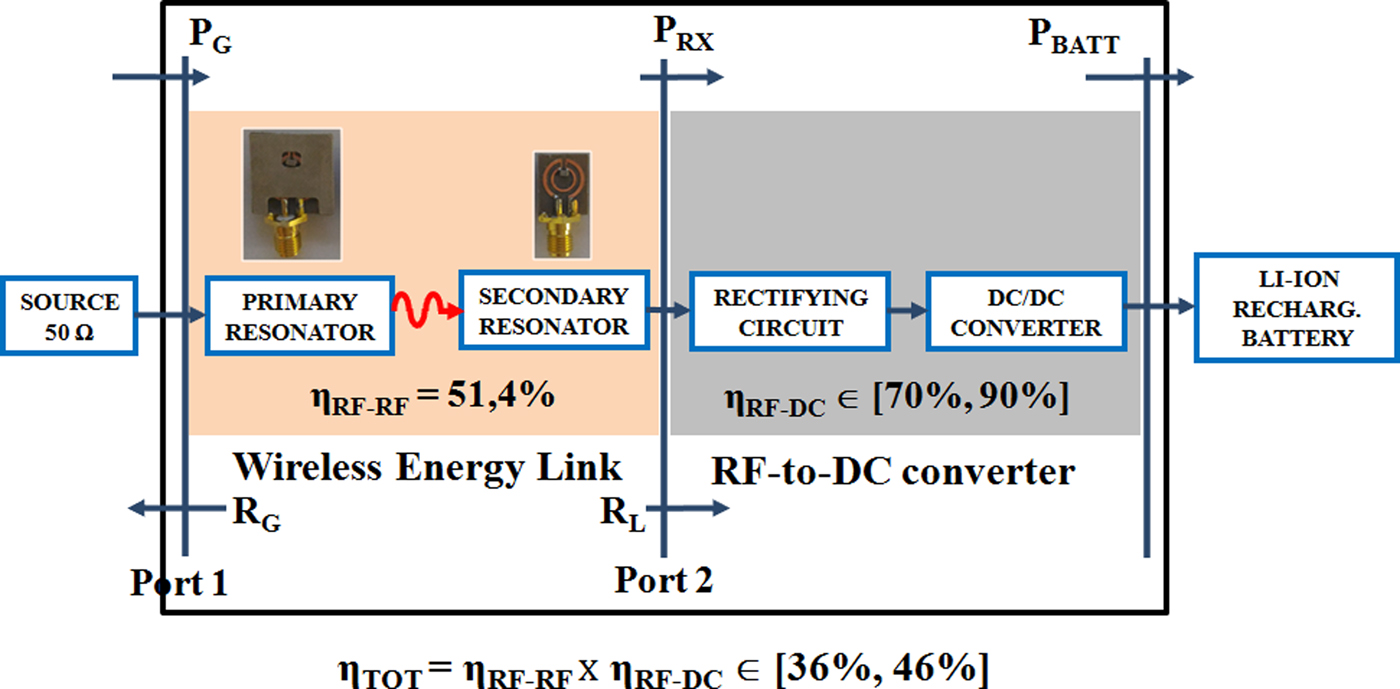
As evident from Fig. 19, the WPT link is connected to the battery through an RF-to-DC converter consisting of a rectifier and a DC–DC converter. The aim of this block is to convert the RF signal at the output port of the WPT link into a DC signal suitable to be used for recharging the battery.
Referring to Fig. 19, the efficiency of the cascade of the WPT link and the battery charger is given by:
 $$\eqalign{\eta _{TOT} & = \displaystyle{{P_{BATT}} \over {P_G}} = \left( {\displaystyle{{P_{BATT}} \over {P_{RX}}}} \right) \times \left( {\displaystyle{{P_{RX}} \over {P_G}}} \right) \cr & = \eta _{RF- DC} \times \eta _{RF- RF}.}$$
With regard to Li-ion batteries, the battery charger can be implemented by using a full-bridge rectifier and a DC/DC boost converter; the typical values that can be obtained for η RF−DC are in the range of 70–90% [Reference Campi, Cruciani, De Santis and Feliziani22, Reference Fu, Ma and Zhu36−Reference Cavalheiro, Moll and Valtchev40]. Additionally, experimental results reported in [Reference Fu, Ma and Zhu36] demonstrate that the efficiency of the RF-to-DC converter is nearly independent of the impedance seen at the input and at the output port of the converter. According to the results reported in the literature, it can be assumed that for an RF-to-DC converter optimized for connecting the proposed WPT link to a Li-ion battery, values in the range of 70–90% can be realized for the η RF−DC . As a consequence, according to (2) for the efficiency of the overall wireless charger, values in the range from 36 to 46% can be considered.
In order to verify if values of η TOT in the range of 36–46% are sufficient to recharge the Li-ion battery of the medical implant, the following formula can be used for calculating the maximum value of the capacity of the battery, which can be recharged for a given value of η TOT :
 $$C_{{\rm max}} = \eta _{TOT} \times P_G \times \displaystyle{1 \over {V_{ch\arg e}}} \times T_{ch\arg e} \times \displaystyle{1 \over {0.2}}.$$
In fact, the capacity of a battery that can be recharged in a charging time T charge with a current I charge is given by:
 $$\eqalign{C_{\max} & = I_{ch\arg e} \times T_{ch\arg e} \times \displaystyle{1 \over {0.2}} \cr & = \displaystyle{{P_{BATT}} \over {V_{ch\arg e}}} \times T_{ch\arg e} \times \displaystyle{1 \over {0.2}}}.$$
where the maximum value usually assumed by V charge is 4.1 V, and P BATT is the DC power provided by the wireless charger to the battery, which can be expressed as:
 $$P_{BATT} = \eta _{RF- DC} \times \eta _{RF- RF} \times P_G = \eta _{TOT} \times P_G.$$
As per the factor 1/0.2 that appears in (3), it is due to the fact that in order to lengthen the lifetime of a Li-ion battery, a full discharge should be avoided. In particular, a good practice is to recharge the battery when its charge is 20% below the maximum level.
From (3) it is evident that for given values of η TOT and T charge , the maximum value of the capacity of a Li-ion battery, which can be recharged depends on P G . Accordingly, in order to verify the feasibility of using the proposed WPT link for recharging the battery of the medical implant, it is necessary to calculate the maximum value of the power, which can be provided to the primary resonator in compliance with safety regulations. This aspect will be analyzed and discussed in the next subsection.
B) Wireless charger: compliance with safety regulations
In the frequency range of interest, i.e. the MedRadio band centered at 403 MHz, safety guidelines provide restrictions for electromagnetic fields in terms of the SAR [41, 42]. Current guidelines impose limits on the peak spatial-averaged SAR, that is the peak SAR averaged on a reference mass of tissue, typically 1 or 10 g [41, 42]. In particular, for the trunk area, the exposure limit considering a mass of 10 g is 2 W/kg.
Accordingly, full-wave simulations were performed with CST Microwave Studio in order to determine the maximum value of the power, which can be provided to the primary resonator of the proposed WPT link in compliance with the 2 W/kg imposed by safety regulations on the peak spatial-averaged SAR.
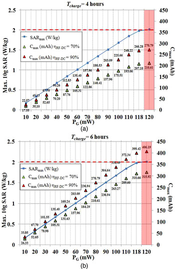
The results obtained this way are given in Fig. 20. The continuous blue line is the 10 g average SAR calculated for different values of P
G
. As it can be seen, values lower than the limit imposed by safety regulations have been obtained for P
G
<118 mW. In Fig. 20, the triangles are the values of the maximum capacity that can be recharged in a charging time of 4 h (Fig. 20(a)) and 6 h (Fig. 20(b)). The green triangles refer to the case of an RF-to-DC converter with an efficiency equal to 70%, while the red triangles refer to an RF-to-DC converter with an efficiency equal to 90%. The value of 4.1 V, which corresponds to the worst case, has been assumed for
 $V_{ch\arg e}$
.
Results obtained by full-wave simulations for the 10 g average SAR by varying the value of the power provided to the primary resonator (continuous blue line). The triangles are the maximum values of the capacity, which can be recharged in a charging time of 4 h (a) and 6 h (b). In more detail, the green triangles refer to the case of a battery charger with an efficiency η RF−DC equal to 70%; while the red triangles refer to the case a battery charger with an efficiency η RF−DC equal to 90%. The red dashed line is the limit imposed by safety regulations for the 10 g average SAR.

As it can be seen, the maximum value of the capacity of a Li-ion battery, which can be recharged in compliance with safety regulation, is in the range of 207–399 mAh.
Considering that the typical value of the capacity of the battery adopted by pulse generators for DB and cardiac stimulation is in the range of 0.5–325 mAh, the results summarized in Fig. 20 confirm that it is feasible to use the proposed link for recharging these devices.
More in general, the results achieved for the WPT link presented in this paper demonstrate the feasibility of using the MedRadio band for energizing medical devices implanted in the chest at a depth of some millimeters.
VI. CONCLUSION
In this paper, a WPT link operating in the MedRadio band and optimized for recharging a medical device implanted in the chest has been proposed. Results referring to a prototype embedded in the silicone header of a pulse generator such the ones adopted for cardiac or DB stimulation have been presented. From experimental data achieved by using a minced pork for simulating the presence of human tissues, an RF-to-RF power transfer efficiency of about 51% has been demonstrated.
The feasibility of using the proposed link for recharging the medical implant in compliance with safety regulations and with a reasonable charging time has been also discussed. It has been demonstrated that the achieved performance allows recharging in 4 h a Li-ion battery with a maximum capacity of 266 mAh.
ACKNOWLEDGEMENTS
This work was supported by ‘Fondo di Sviluppo e Coesione 2007–2013 – APQ Ricerca Regione Puglia “Programma regionale a sostegno della specializzazione intelligente e della sostenibilità sociale ed ambientale – FutureInResearch”. The authors would like also to thank Dr. Ennio Pisanò for his valuable advice and discussions.
 Giuseppina Monti (M'16-SM'16) received the Laurea degree in Telecommunication Engineering (with honors) from the University of Bologna, Bologna, Italy, in 2003, and the Ph.D. degree in Information Engineering from the University of Salento, Lecce, Italy, in 2007. She is currently with the Department of Innovation Engineering, University of Salento, Lecce, Italy, as a Temporary Researcher and Lecturer in CAD of microwave circuits and antennas. Her current research interest includes the analysis and applications of artificial media, the design and realization of microwave components, MEMS-based reconfigurable antennas and devices, rectennas, and systems and devices for wireless power transmission applications. She has co-authored three book chapters and more than 100 papers in international conferences and journals.
 Maria Valeria De Paolis received the M.S. degree in Telecommunications Engineering (cum laude) from the University of Salento, Lecce, Italy, in 2014. She is a Ph.D. student at the University of Salento. Her research activity is focused on the design of wireless power transfer systems for biomedical applications.
 Laura Corchia was born in Italy, in 1980. She received the M.S. degree in Telecommunication Engineering and the Ph.D. in Information Engineering from the University of Salento, Lecce, Italy, in 2007 and 2011, respectively. She is currently a Postdoctoral Researcher with the Department of Engineering for Innovation, University of Salento. Her research interests include the development of near- and far-field wireless power transfer links and power management units for wearable applications, the design and the fabrication of reconfigurable antennas, the characterization of antennas and microwave devices.
 Mauro Mongiardo (F'11) has received the Laurea degree (110/110 cum laude) in Electronic Engineering from the University of Rome “La Sapienza” in 1983. In 1991, he became Associate Professor of Electromagnetic Fields, and from 2001, he is a Full Professor of Electromagnetic Fields at the University of Perugia. He has been elected Fellow of the IEEE for “for contributions to the modal analysis of complex electromagnetic structures” in 2011. The scientific interests of Mauro Mongiardo have concerned primarily the numerical modeling of electromagnetic wave propagation both in closed and open structures. His research interests have involved CAD and optimization of microwave components and antennas. Mauro Mongiardo has served in the TPC of the IEEE IMS from 1992. From 1994, he is a member of the Editorial Board of the IEEE TMTT. During the years 2008–2010, he has been associate editor of the IEEE TMTT. He is author or co-author of over 200 papers and articles in the fields of microwave components, microwave CAD, and antennas. He is the co-author of the books “Open Electromagnetic Waveguides” (IEE, 1997) and “Electromagnetic Field Computation by Network Methods” (Springer, 2009).
 Luciano Tarricone received the Laurea degree in Electronic Engineering (cum laude) and Ph.D. degree from Rome University “La Sapienza”, Rome, Italy, in 1989 and 1994, respectively. From 1990 to 1992, he was a Researcher with the IBM Rome Scientific Centers. From 1992 to 1994, he was with the IBM European Center for Scientific and Engineering Computing, Rome, Italy. Between 1994 and 1998, he was a Researcher with the University of Perugia, Perugia, Italy, and between 1998 and 2001, he was a “Professore Incaricato” of electromagnetic (EM) fields and EM compatibility. Since November 2001, he has been a Faculty Member with the Department of Innovation Engineering, University of Salento, Lecce, Italy, where he is a Full Professor of EM fields and coordinates a research group of about 15 people. He has authored and co-authored approximately 300 scientific papers. His main contributions are in the modeling of microscopic interactions of EM fields and biosystems, and in numerical methods for efficient CAD of microwave circuits and antennas. He is currently involved in bioelectromagnetics, electromagnetic energy harvesting and wireless power transmission, novel CAD tools and procedures for microwave circuits, RFID, and EM high-performance computing.