Introduction
Reflectarray antennas based on metasurfaces have emerged as promising solutions for various wireless communication and radar applications, owing to their low-profile configuration, high gain, and reconfigurable beam-control capabilities [Reference Sangmahamad, Janpugdee and Zhao1–Reference Wang, Tian, Jiang, Chen, Zhang and Cui6]. In conventional reflectarray designs, the reflection phase distribution across the aperture is generally realized via analog metasurface elements, which require continuous phase adjustment and extensive electromagnetic optimization. This approach, although effective, typically involves intricate design processes and a strong dependence on precise material and structural parameters. As an alternative, digital coding metasurfaces have been proposed to simplify the design procedure, wherein the reflection phase of each cell is discretized – often to just two states of 0° and 180° – to form a 1-bit coding scheme [Reference Kan, Yang, Zhang, Lei, Jiao and Li7–Reference Xu, Jiang, Cai, Bai and Cui9]. By mapping different 1-bit codes onto the reflectarray surface, flexible wavefront manipulation can be achieved with reduced complexity and better adaptability to modern communication requirements [Reference Bashir, Singh and Dubey10].
Despite these advantages, implementing multiband or wideband operation in a 1-bit coding metasurface remains a notable challenge because a single resonator geometry typically provides optimal performance over a limited frequency range [Reference Luo, Ren, Wang, Cheng and Cui11–Reference Afzal, Esselle and Koli13]. To address this issue, hybrid metasurface strategies have been explored, wherein multiple resonant elements or active components are integrated into each unit cell [Reference Vinod and Khairnar14, Reference Xi, Jiang, Wei, Hong, Cheng and Gong15]. Such an approach decouples the phase adjustment mechanism at different frequency bands, making it possible to independently steer beams or generate diverse radiation patterns across multiple bands. This concept offers enhanced functionality in emerging systems that demand simultaneous multiband coverage, such as satellite communication, radar imaging, and high-throughput wireless networks.
Motivated by the need for efficient, multiband beam-steering antennas, this work presents a dual-band, four-beam, 1-bit hybrid active/passive metasurface reflectarray. Specifically, each unit cell comprises two parts: (i) an active double-split square ring with PIN diodes that provides 180° phase switching in the lower band at 5.8 GHz, and (ii) a passive cross-shaped patch whose dimensions are tailored to yield a 180° phase difference in the higher band at 9.7 GHz. By arranging these cells in a chessboard-like 1-bit coding sequence, the proposed antenna independently steers four beams at each frequency band without necessitating additional hardware layers. A 15 × 15 prototype has been fabricated and tested, demonstrating stable four-beam operation in both bands. The measured 3-dB beamwidths are approximately 10.2° at 5.8 GHz and 11.5° at 9.7 GHz, while the steering angles are 19° and 12.1°, respectively. A good agreement between simulated and experimental results underscores the effectiveness of this design in achieving multiband, low-profile, and reconfigurable beam control.
The remainder of this paper is organized as follows. The following section details the configuration and phase characteristics of the hybrid active/passive unit cell. The “Hybrid active/passive metasurface antenna design” section describes the reflectarray design methodology, including the chessboard coding arrangement and bias network. The “Simulation and measurement results” section validates the proposed design through experimental measurements, comparing the results with simulations in both frequency bands. Finally, the “Conclusion” section concludes the paper and discusses future directions for further performance optimization and functional expansion of hybrid coding metasurface antennas.
Hybrid active/passive element design
To achieve dual-band, four-beam radiation at 5.8 and 9.7 GHz, a 1-bit coding metasurface element composed of an active double-split square ring (with PIN diodes) and a passive cross-shaped patch is proposed. By integrating these two structures into a single reflective unit cell, independent 180° phase control is realized at each frequency band without increasing the antenna’s overall profile or complexity.
Element configuration
A schematic of the proposed hybrid active/passive element is shown in Fig. 1. The outer ring incorporates PIN diodes (BAP70-03) placed at the splits for dynamic phase switching at 5.8 GHz, while the inner region hosts a cross-shaped patch with optimized dimensions for passive phase tuning at 9.7 GHz. Both metallic patterns are printed on the top side of a polytetrafluoroethylene (PTFE) substrate (ε r = 2.55, h 1 = 2 mm), and a continuous metal ground plane is located on the backside to ensure total reflection. Figure 1(c) shows the transverse equivalent transmission line model of the unit cell, where Z A represents the equivalent impedance of the metal element and Z S denotes the equivalent impedance of the dielectric.
Schematic of the 1-bit hybrid active/passive metasurface element. (a) Perspective view, (b) Top view, and (c) Transverse equivalent transmission line (TEM) model.

When the PIN diodes switch between ON and OFF states (modeled by a small series resistance R = 1.5 Ω in the ON state and a small capacitance C = 0.1 pF in the OFF state), the outer ring exhibits two reflection phases at 5.8 GHz differing by approximately 180°. Meanwhile, the cross-shaped patch dimensions px are adjusted to yield a 180° phase difference at 9.7 GHz. Table 1 summarizes the primary geometric parameters of the dual-band element.
Structural parameters of the proposed hybrid element

Reflection phase characteristics
Full-wave simulations (CST Microwave Studio) were performed to characterize the reflection phase under normal incidence of a y-polarized plane wave. Figure 2 illustrates the key results:
(i) Active double-split square ring for 5.8 GHz
(a) Schematic of Floquet ports. (b) Reflection characteristics of the reflection unit cell when y-polarized waves incidence.

In the lower frequency band at 5.8 GHz, the outer double-split square ring with integrated PIN diodes provides two reflection phase states that approximate a 180° difference. Specifically, when both the diode ON/OFF states and the cross-patch arm length p x are varied, the simulated reflection phases of the element are 164.7°, 165.0° and −10.2, −11.4°. Notably, altering px in this process affects the reflection phase at 5.8 GHz by less than 1.2°. Consequently, the phase difference induced solely by switching the diodes ranges between 174.9° and 176.4°, well within the 180° ± 20° requirement for 1-bit coding. These results demonstrate that the active double-split ring can effectively generate the two discrete phase states needed for reconfigurable operation at the lower frequency band.
(ii) Passive cross-shaped patch for 9.7 GHz
In the higher frequency band at 9.7 GHz, the inner cross-shaped patch is designed to achieve a 180° phase difference while minimizing interference from the diode states. When both the diode ON/OFF configurations and the cross-patch length p x are varied, the simulated reflection phases are 106.7°, 101.3°, and −71.7, −75.6°. Notably, changes in the diode’s states induce less than 5.2° variation in the high-frequency reflection phase. As a result, the total phase difference across all four possible states spans 173° to 182.3°, comfortably meeting the 180° ± 20°
In both bands, the total achievable phase difference meets the 1-bit coding requirement (i.e., 180° ± 20°) crucial for constructing a dual-band, 1-bit coding metasurface.
DC bias circuit design
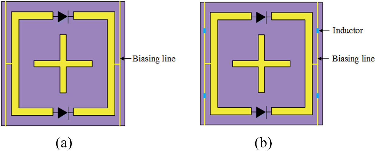
A DC bias network is required to supply the PIN diodes while introducing minimal perturbation to the reflection characteristics. As illustrated in Fig. 3(a), thin bias lines (0.2 mm width) extend from the diode terminals to the circuit boundary. To mitigate the desired radio frequency coupling through these lines, small inductors (10, 20, or 30 nH) are inserted in series, as depicted in Fig. 3(b). Parametric studies confirm that a 20 nH inductor best preserves the original reflection phase performance at both frequency bands.
Reflection unit cell bias circuit design. (a) Coding element with bias lines. (b) Coding element with bias lines and inductors.

Figures 4 and 5 show the reflection phases for ON- and OFF-diode states before and after adding bias lines and inductors. The overall phase curves at 5.8 and 9.7 GHz remain stable, with fluctuations within a few degrees of reference design (i.e., without bias lines). Consequently, the final element layout – incorporating 0.2 mm-wide bias lines and 20 nH inductors – meets the 1-bit phase-switching requirement while providing a reliable DC supply path for the diodes.
Influence of inductors on unit reflection characteristics – “ON” state (a) px = 8.7 mm. (b) px = 9.4 mm.

Influence of inductors on unit reflection characteristics – “OFF” state (a) px = 8.7 mm. (b) px = 9.4 mm.

Hybrid active/passive metasurface antenna design
In this section, a dual-band reflectarray antenna is designed using the hybrid active/passive element described in the “Hybrid active/passive element design” section. The primary objective is to achieve four-beam radiation at both 5.8 and 9.7 GHz by arranging the hybrid elements in a chessboard coding pattern. The proposed reflectarray comprises (i) a feeding horn and (ii) a 15 × 15 metasurface array with integrated DC bias lines.
Overall antenna configuration
Figure 6 illustrates the overall configuration of the dual-band coding metasurface and its application in a reflectarray antenna. As shown in Fig. 6(a) and (b), the metasurface layer is composed of 15 × 15 hybrid active/passive elements, forming 5 × 5 “coding blocks,” each block consisting of 3 × 3 unit cells. These blocks are arranged in a chessboard-like sequence “0101…/1010…,” enabling a 1-bit reflection phase difference (0° or 180°) across the array at both frequency bands.
(a) Schematic of the proposed reflectarray including feed horn, support and metasurface. (b) Top view of the designed dual-band coding metasurface. (c) Perspective view of the meatasurface.

Bias network design
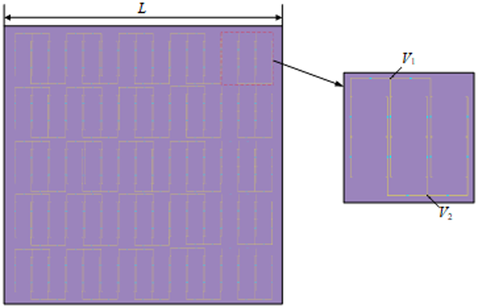
Figure 7 shows a schematic of the bias network used to control the PIN diodes within each active hybrid unit cell. Each 3 × 3 block of elements is connected in parallel through 0.2 mm-wide metal bias lines, ultimately leading to two feed points labeled V 1 and V 2 (one for the bias voltage supply and one for ground). By changing the DC voltage at V 1 relative to V 2, each PIN diode can be switched between ON and OFF states, thus enabling the 0°/180° reflection-phase transitions for the lower frequency band (5.8 GHz).
Schematic of the bias network.

To minimize the impact of the bias lines at microwave frequencies, several 20 nH inductors are inserted in series along each bias line. These inductors block high-frequency currents, ensuring that the presence of DC lines does not significantly alter the reflection-phase response. No additional dielectric substrate layers are introduced; the bias circuitry is patterned on the same PTFE substrate that supports the metasurface elements.
Simulation and measurement results
A prototype reflectarray antenna, shown in Fig. 8(a), was fabricated to experimentally validate the proposed design. The 15 × 15 metasurface measures 320 mm × 320 mm, printed on a PTFE substrate with a continuous ground plane on the backside. SMA or pin-header connectors are soldered to the voltage input ports for convenient biasing. The structure is fed by a standard horn antenna, and a sliding mechanism allows adjusting the horn-to-aperture distance for measurements at 5.8 and 9.7 GHz. All testing was carried out using an Agilent E8362B vector network analyzer and standard far-field measurement facilities, as illustrated in Fig. 8(b).
(a) Top view of the fabricated reflectarray prototype. (b) Measurement setup in a far-field anechoic chamber.

Figure 9 compares the measured and simulated reflection coefficients (|S 11|) in the lower and higher frequency bands. Despite minor discrepancies, the measured results agree well with simulations. At the lower band, the −10 dB impedance bandwidth extends from 5.16 to 6.09 GHz (∼16.03% fractional bandwidth). At the higher band, the −10 dB impedance bandwidth extends from 9.24 to 10.4 GHz (∼11.95% fractional bandwidth). Slight deviations from simulation can be attributed to tolerances in material parameters and manufacturing.
Comparison of simulated and measured reflection coefficients of the reflectarray antenna at (a) The lower band. (b) The higher band.

Figure 10 presents the measured and simulated 2-D radiation patterns at 5.8 and 5.85 GHz. Two principal cuts, corresponding to φ = 45° and φ = 135°, are shown. In the φ = 45° plane [Fig. 10(a)], the measured beam steering angle differs from simulation by ∼1.8°, while the half-power beamwidth (HPBW) differs by ∼4.5°. Similarly, in the φ = 135° plane [Fig. 10(b)], the measured beam steering angle and HPBW show slight deviations of 1.2° and 2.6°, respectively. The observed differences largely result from fabrication tolerance and measurement environment.
Measured and simulated 2-D radiation patterns of the proposed antenna at 5.8 and 5.85 GHz for (a) φ = 45°. (b) φ = 135°.

As illustrated in Fig. 11, four-beam radiation patterns were also achieved in the higher frequency band. At 9.7 and 9.8 GHz, the measured beam steering angles deviate by ∼0.8° and 2.4° (for φ = 45° and φ = 135°, respectively), and the HPBW deviations remain within 3°. Overall, the results confirm stable multi-beam performance in both bands, consistent with simulation.
Measured and simulated 2-D radiation patterns of the proposed antenna at 9.7 and 9.8 GHz for (a) φ = 45°. (b) φ = 135°.

Table 2 summarizes the performance of the proposed reflectarray antenna in comparison with selected multi-beam designs reported in Refs [Reference Cui, Du and Lin3–Reference Kan, Yang, Zhang, Lei, Jiao and Li7]. Compared with traditional multi-beam antennas, the proposed design adopts chessboard coding and a low-interference bias network, boasting a simpler structure and higher stability. Compared with single-band multi-beam reflectarray antennas [Reference Zhang, Dai, Fu, Tang and Mi4, Reference Mirmozafari, Ma, Dagefu and Behdad5], the metasurface reflective array antenna proposed in this paper can achieve independent four-beam steering in two frequency bands (5.8 and 9.7 GHz) respectively, making it suitable for scenarios requiring simultaneous communication and detection. Instead of relying on intricate phase shifters or multi-feed reflectarray systems [Reference Mirmozafari, Ma, Dagefu and Behdad5,Reference Kan, Yang, Zhang, Lei, Jiao and Li7], we use a 1-bit chessboard coding pattern to realize beam steering, reducing system complexity and power consumption. However, the −10 dB impedance bandwidth at 9.7 GHz is 11.95% (9.24–10.4 GHz), which is narrower than some wideband multi-beam reflectarray designs [Reference Mirmozafari, Ma, Dagefu and Behdad5,Reference Bashir, Singh and Dubey10]. This limits adaptability to scenarios requiring ultra-wideband operation. As shown, the proposed design offers dual-frequency operation, four-beam capability, and relatively narrow beamwidths, making it suitable for modern radar and wireless communication systems demanding multiband reconfigurable beam control.
Performance comparison of the proposed antenna with related works

Conclusion
In conclusion, a dual-band multi-beam reflectarray antenna integrating a single-layer hybrid active/passive element was successfully demonstrated, realizing 1-bit reflection-phase switching at 5.8 and 9.7 GHz. By combining PIN diodes in a double-split square ring for the lower band and a cross-shaped patch for the higher band, arranged in a chessboard coding pattern, the design achieves four-beam steering at each frequency. A 15 × 15 prototype confirms stable multi-beam operation with measured beam deflection angles of 19° and 12.1° and 3-dB beamwidths of 10.2° and 11.5°, respectively, in good agreement with simulations. The core innovation of this paper lies in the adoption of an active-passive hybrid, single-layer decoupling strategy. This strategy integrates active and passive components for phase control into a single substrate, enabling the antenna to maintain a low-profile structure while avoiding the manufacturing tolerance issues that commonly plague conventional dual-band metasurfaces. This low-profile, reconfigurable metasurface design shows strong potential for multiband wireless communications and radar applications, and future work will explore bandwidth enhancement and advanced coding strategies.
Acknowledgements
This work was supported by the National Science Foundation of China (62071282).
Competing interests
The authors report no conflict of interest.

Chunyan Liu received the B.E. degree in School of Physics and Electronic Engineering, Shanxi University in 2021. She is currently pursuing the M. E degree in School of Physics and Electronic Engineering, Shanxi University, Taiyuan, China. His research is mainly focused on reflectarray antenna design.

Li Liu received the B.E. degree in Electronic Information Science and Technology, Liaoning University in 2021. He is currently pursuing the M. E degree in School of Physics and Electronic Engineering, Shanxi University, Taiyuan, China. His research is mainly focused on reflectarray antenna design.

Yufeng Liu was born in Shanxi Lvliang, China, in 1986. He received the PhD degree in radio physics from Sichuan University, Sichuan, China, in 2014. In 2015, he joined the College of Physics and Electronic Engineering, Shanxi University. His research is mainly focused on computational electromagnetics and antenna design.

Liping Han was born in Shanxi Shuozhou, China, in 1970. She received the B.S., M.S. and Ph.D. degrees in electronic engineering from Shanxi University, Taiyuan, China, in 1993, 2002, and 2010, respectively. Currently, she is a professor with the College of Physics and Electronic Engineering, Shanxi University. Her research interests include microwave and millimeter-wave integrated circuits and microstrip antenna.

Fangyuan Chen is a Senior Engineer, and the Deputy Director of the Research Institute of Zhejiang Jinyichang Technology Co., Ltd. He obtained his Ph.D. degree in 2016, and is a jointly-trained Ph.D. from Cornell University and Sichuan University. He also is the Enterprise Graduate Supervisor at Southeast University and Shanxi University. His research focuses on Antenna theory & design (array antennas, millimeter-wave antenna systems), microwave circuits & systems, and automobile wireless communication systems.