
Introduction
Shape memory alloys (SMAs) are a unique class of functional materials with the ability to convert thermal energy into mechanical work by recovering their shape upon an increase in temperature. Nitinol (NiTi) is by far the most popularly used SMA due to its excellent mechanical properties, biocompatibility, and corrosion resistance.[Reference Elahinia, Shayesteh Moghaddam, Taheri Andani, Amerinatanzi, Bimber and Hamilton1–Reference Ma, Franco, Tapia, Karayagiz, Johnson, Liu, Arroyave, Karaman and Elwany4] In addition, NiTi exhibits superior shape memory and superelastic effects, capable of restoring large strains up to 8% by heating and unloading, respectively.[Reference Kumar and Lagoudas5]
Owing to these physical and functional properties, NiTi has found application in a variety of industries such as sensing and actuation (aerospace), dampening (automotive), implants, and fixtures (biomedical).[Reference Elahinia, Shayesteh Moghaddam, Taheri Andani, Amerinatanzi, Bimber and Hamilton1,Reference Khoo, Liu, An, Chua, Shen and Kuo2,Reference Kumar and Lagoudas5] However, further advancing functionality in these applications will likely require components with complex geometries, and NiTi is challenging to process, shape, and form. NiTi's high ductility makes it difficult to machine, limiting parts to simplistic form factors such as wires, plates, bars, and tubes.[Reference Elahinia, Shayesteh Moghaddam, Taheri Andani, Amerinatanzi, Bimber and Hamilton1,Reference Khoo, Liu, An, Chua, Shen and Kuo2,Reference Kumar and Lagoudas5,Reference Dadbakhsh, Speirs, Van Humbeeck and Kruth6] Furthermore, the well-known shape memory effect is highly sensitive to Ni:Ti composition, impurities (carbon and oxygen), and secondary phase precipitates (Ti-rich and Ni-rich), which can be altered during high-temperature machining or fabrication processes.[Reference Kumar and Lagoudas5]
All of these factors make NiTi, a perfect candidate for additive manufacturing (AM), adding SMAs to the rapidly growing topic area of 4D printing: complex three-dimensional (3D) parts that can undergo controlled shape changes in response to external stimuli.[Reference Elahinia, Shayesteh Moghaddam, Taheri Andani, Amerinatanzi, Bimber and Hamilton1,Reference Khoo, Liu, An, Chua, Shen and Kuo2,Reference Ma, Franco, Tapia, Karayagiz, Johnson, Liu, Arroyave, Karaman and Elwany4,Reference Dadbakhsh, Speirs, Van Humbeeck and Kruth6–Reference Bormann, Schumacher, Müller, Mertmann and de Wild13] There is huge potential to develop novel structures with adaptive capabilities by leveraging superelastic/shape memory properties in combination with the unique processing capabilities of AM. There have been a number of AM studies in the literature on the fabrication of NiTi, focusing on the effects of laser processing parameters on microstructural characteristics (e.g., secondary phases, grain structure, and composition), mechanical behavior, or functional properties.[Reference Elahinia, Shayesteh Moghaddam, Taheri Andani, Amerinatanzi, Bimber and Hamilton1,Reference Khoo, Liu, An, Chua, Shen and Kuo2,Reference Ma, Franco, Tapia, Karayagiz, Johnson, Liu, Arroyave, Karaman and Elwany4,Reference Dadbakhsh, Speirs, Van Humbeeck and Kruth6–Reference Bormann, Schumacher, Müller, Mertmann and de Wild13] However, the resulting processing recommendations are often contradictory between studies when all important factors (e.g., impurities and stoichiometry in addition to propensity to cracking) are considered simultaneously.[Reference Elahinia, Shayesteh Moghaddam, Taheri Andani, Amerinatanzi, Bimber and Hamilton1] Thus, these prior studies have not addressed strategies to additively produce shape-changing NiTi components at length scales relevant for real applications. More broadly, it has been previously demonstrated that AM processing conditions do not always scale directly with build volume: small parts (~1 mm3) may build without any challenges, but large parts (~1 cm3) may crack and delaminate under identical laser parameters.[Reference Jared, Aguilo, Beghini, Boyce, Clark, Cook, Kaehr and Robbins14–Reference DebRoy, Wei, Zuback, Mukherjee, Elmer, Milewski, Beese, Wilson-Heid, De and Zhang16]
In this work, we address the fundamental challenges associated with designing and additively manufacturing functional, stimulus-responsive components from a NiTi shape memory alloy powder. Specifically, this present study targets how to reliably and scalably fabricate NiTi components. We first performed processing parameter sweeps to fabricate single tracks, which were subsequently analyzed for melt pool shape and stability. We then moved to fabricate larger components and examined the impact of build plate composition and geometry on part adhesion, NiTi stoichiometry, and microstructure. By identifying a correlation between hatch spacing and energy parameters, we were able to determine ideal processing parameters for achieving our desired stoichiometry in 3D parts. Lastly, thermally-activated shape change was demonstrated in a complex part. Importantly, this work is a first step in identifying processing solutions to ensure optimal material formation across different build plate materials.
Methods
Materials
NiTi powder, obtained from Hoeganaes, was produced via electrode induction gas atomization (EIGA) of a 55Ni–45Ti wt% bar in an argon environment. The target powder distribution was 10–45 µm for the Renishaw AM400 system. The atomized powder had a D10 of 13.1 µm, a D50 of 27.9 µm, and a D90 of 43.6 µm with an ASTM B212 density of 3.3 g/cm3. The powder distribution and chemical composition are shown in Supplementary Fig. S1 and Table S1. A reduced build volume module was used to minimize the powder consumed during builds. A Ti-6-4 base plate was used and modified to have smaller sub-size inserts of Ti-6-4, N200 (≤99% Ni), and NiTi to evaluate the impact of build substrate on the final deposit.
Laser powder bed fusion
A Renishaw AM400 Selective Laser Melting (SLM) system was used to consolidate the NiTi powder. The system utilizes a 1075 nm, 400 W pulsed laser with a 70 µm spot size. To explore and select optimal laser parameters, a series of single tracks were produced, with variations in the critical laser parameters—laser power (P), point distance (d), and exposure time (t). The initial single-track experiments were conducted using a power of 140–200 W, point distance of 30–70 µm, exposure time of 20–70 µs, and a constant layer height of 30 µm. These ranges were selected based on our prior knowledge fabricating Ti-6-4, Inconel, and other alloys. Qualitatively (d/t) is equivalent to the scan speed in a continuous laser additive process, which approximates the scan speeds in our study to range from 600 to 3250 mm/s.
Following fabrication, each track's melt pool shape and quality were characterized via optical profilometry and x-ray computed tomography (XRCT), as described below. Resulting trends informed the selection of starting laser parameters for fabrication of 3D components. In order to establish hatch spacing for a 3D build, an estimation tool for energy density as a function of laser power, exposure time, and point distance was utilized:[Reference Thijs, Verhaeghe, Craeghs, Van Humbeeck and Kruth17]
 $${\rm ED} = \left( {\displaystyle{{Pt} \over d}} \right)\displaystyle{1 \over {HL}},$$
where ED is volumetric energy density, P is power, t is exposure time, d is point distance, H is hatch spacing, and L is layer thickness. The quantity (Pt/d) represents the linear energy density, which ranged from 58 to 333 J/m in these builds. For 3D components, hatch ratios were set to 20%–50% overlap initially, and then further down-selected to maximize build quality and plate adhesion, which was quantified using XRCT.
Scanning electron microscopy
A Thermo Scientific Scios scanning electron microscope (SEM) was used to perform imaging of the microstructure and to determine the elemental composition of the samples by an energy-dispersive x-ray spectroscopy (EDS). A backscatter detector was used to qualitatively highlight the differences in composition along with the cross section of a single track. EDS line scans were performed at a voltage of 15 kV in order to determine how the elemental composition changed along the thickness of representative tracks. Prior to analysis, tracks were ground using SiC paper and then polished with 0.02 µm colloidal silica.
Optical profilometry
A Zeta-20 optical profilometer was used to determine the top-down morphology of the single tracks. Topographic profiles were made across the single tracks to determine the stability of each track on the build plate. An objective lens of 100× was used to collect the topographical images with a z-interval of 0.185 µm between each image. This objective lens was chosen to capture a large portion of the single track while minimizing the depth of field error.
X-ray computed tomography
XRCT was used for nondestructive evaluation of the single tracks and build plate interactions. The specimens were scanned using a North Star Imaging X-50 cabinet with a 225 kV micro-focus x-ray source. Volumetric reconstruction and analysis were performed using North Star Imaging efX-CT and Volume Graphics VGStudio MAX. The single-track sample was cut from the plate via electrical discharge machining and scanned in one piece. Test cylinders were scanned on the build plate or a small region of the build plate, when possible.
Results and discussion
To inform the selection of processing conditions for a large scale, NiTi components (with densities greater than 99.7%), we initially fabricated and analyzed single tracks for melt pool stability, shape, and chemistry. This enabled down-selection of parameters for 3D builds, which were analyzed for build quality and substrate adhesion. Compilation of the single-track and 3D build results were utilized for final optimization of scalable NiTi AM.
Melt pool width and stability
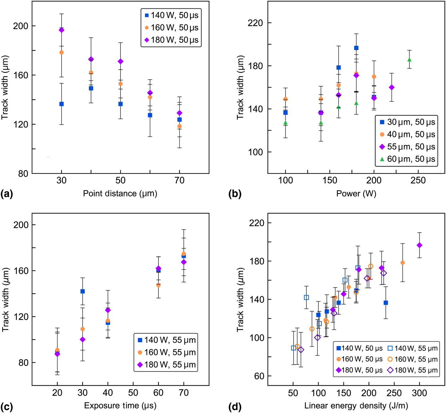
The relationships between laser parameters—power (P), exposure time (t), and point distance (d)—and a single-track melt pool width were quantified using optical profilometry (Supplementary Table S2). The sensitivity of the melt pool width to each laser parameter was evaluated independently (Figs. 1(a)–1(c)). The width of single tracks shifted modestly across our range of point distance values (from ~125 to 175 µm) and laser power values (from ~130 to 175 µm). However, we found that the width of the single tracks changed most dramatically, as we varied the laser exposure time (from ~80 to 175 µm). Finally, the track width data can be plotted versus the combined linear energy density (Pt/d), and a strong linear correlation was observed (Fig. 1(d)). The track width values were used below to determine the hatch spacing that leads to 20% melt pool overlap.
Single-track melt pool width as a function of (a) laser point distance, (b) exposure time, (c) power, or (d) linear energy density (Pt/d). The legend for each plot specifies P, t, and/or d for each series.

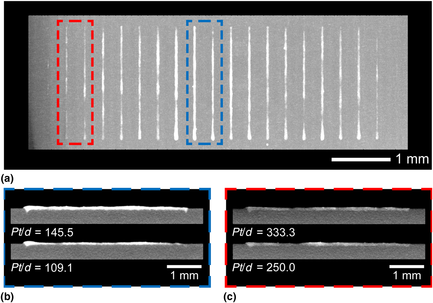
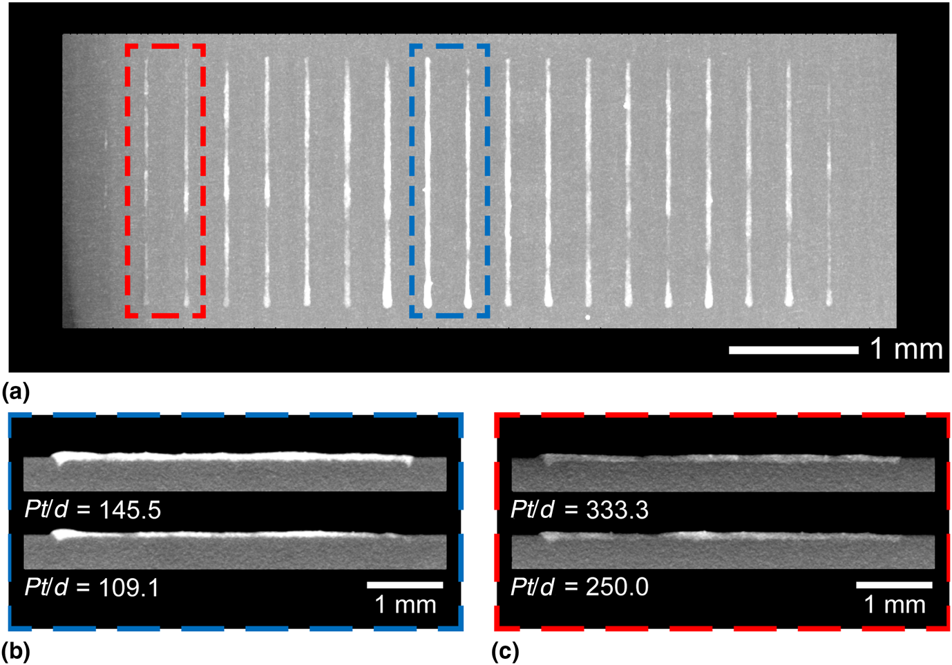
The track width data above is critical to determine the hatch spacing for 3D builds, but stability analysis is also required to inform optimal laser parameters. Figure 2 qualitatively illustrates representative unstable (Fig. 2(b)) and stable (Fig. 2(c)) melt pool tracks imaged via XRCT. Owing to the difference in average x-ray attenuation between the track and substrate materials, the tracks are clearly distinguished from the substrate. A deviation of less than 10% in track width along the track length, shown in Fig. 1(a), was deemed sufficiently stable to avoid build porosity. In general, it was observed that single tracks processed using a lower energy density (e.g., 110 or 140 J/m) were more stable than those processed with a higher energy density (e.g., 267 or 333 J/m). It has been noted in computational and experimental studies that the probability of melt pool instabilities—e.g., denudation, spattering, and pore defects—increase with higher energy densities, and lack of fusion defects tend to form at lower energy densities.[Reference Matthews, Guss, Khairallah, Rubenchik, Depond and King18–Reference King, Anderson, Ferencz, Hodge, Kamath and Khairallah20] Based on this knowledge, and our own results, energy density conditions in the 100–200 J/m range were down-selected for melt pool chemistry analysis.
Representative XRCT scans of NiTi single tracks (white) on a Ti-6-4 build plate (dark). (a) Top projection of XRCT scans. (b) Lengthwise cross sections through line tracks that show poor consistency and stability throughout the track length. (c) Lengthwise cross sections through line tracks that are stable throughout the track length.
Melt pool chemistry
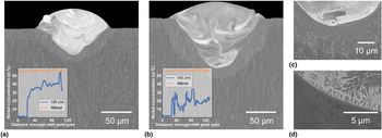
The composition of tracks with the most consistent widths were evaluated using SEM and EDS. A comparison of two representative tracks (the two identified as stable in Fig. 2(b)) is shown in Fig. 3. The contrast in these images qualitatively highlights the grain structure and where there are differences in the Ni:Ti chemistry—primarily due to the relative differences in the atomic numbers of nickel and titanium. The insets in Figs. 3(a) and 3(b) show a significant variation in Ni composition through the melt pool height (blue lines). There are regions within the tracks, especially toward the top of the 110 J/m sample, that approach the powder stoichiometry. However, large regions of the melt pool exhibit nonideal Ni:Ti ratios that diverge from that of the starting powder (orange lines); it should be noted that these lines should be treated semi-quantitatively because the typical error of EDS measurements can be several percent. Understanding how to control the stoichiometry is critical since achieving shape memory response in a 3D part relies upon Ni:Ti ratio.
Electron micrograph melt pool cross sections of representative stable single tracks: (a) Pt/d = 110.1 J/m and (b) Pt/d = 140.0 J/m. (Insets) EDS line collected at the midplane of the track (solid and dashed blue lines) demonstrating the changes in Ni composition from the base to top of melt pool; (orange line) EDS line collected from a melt pool built on a NiTi base plate under similar laser processing conditions. (c) Magnified electron micrograph from the base of the melt pool in (b) showing the heat-affected zone. (d) Magnified electron micrograph from the base of the melt pool in (b) and (c), highlighting NiTi intermetallic formation due to chemical mixing with the substrate.

These Ni:Ti compositional variations are likely caused by the NiTi powder reacting with the Ti-6-4 substrate in the heat-affected zone (Fig. 3(c)). Based on the phase diagram, and confirmed in Fig. 3(d) and Supplementary Fig. S2, NiTi2 precipitates form close to the interface between the substrate and powder prior to NiTi melt pool solidification. It is important to minimize the formation of these deleterious phases because not only do they impact the part's superelasticity/shape memory response, they also lead to brittle failure via delamination at the substrate/part interface. This can be seen in Supplementary Fig. S3, which shows a cylinder built on a Ti-6-4 build plate with a high Pt/d of 181 J/m (P = 200 W, d = 55 µm, h = 105 µm, and t = 50 µs). To test the hypothesis that the NiTi and Ti-6-4 are reacting during the build, we fabricated single tracks on a NiTi build plate (Supplementary Fig. S4), which resulted in NiTi composition nearly identical to that of the original powder, throughout the melt pool heights.
Although utilizing a NiTi build plate is one route to help minimize these changes in stoichiometry during processing, maintaining manufacturability on a cost-effective substrate like Ti-6-4 is important for future scalability. As a result, we considered melt pool stoichiometry as an additional constraint when optimizing processing parameters for 3D builds. Qualitatively, the most stoichiometrically homogenous melt pool (on Ti-6-4) was that built with the lowest energy density (Pt/d = 110 J/m), whereas a high energy density builds resulted in titanium-rich chemistry (Fig. 3). Lower energy densities are preferable for maintaining homogeneous stoichiometry because melt pool volume in the build plate is smaller, which decreases the degree of chemical. Serendipitously, this trend of optimal chemistry with lower energy densities is consistent with that found for melt pool stability.
Sample adhesion to build plate
Vertical slices through the 3D cylinder in Supplementary Fig. S4 show a transition from a defect-free build plate, to a cracked interface, but eventually resulting in a fully dense cylinder. Sample adhesion to the substrate was suspected to be disrupted by chemical inhomogeneities and intermetallic formation at the part/build plate interface. XRCT allowed us to probe this interface and directly quantify the part/substrate contact radius. It can be seen in Supplementary Fig. S5a that the contact radius on the Ti-6-4 build plate is marginally larger when lower energy density (Pt/d = 110 J/m, h = 105 µm) processing conditions are used, but delamination is present regardless. To further explore build plate composition effects, we also built on an N200 substrate (Supplementary Fig. S5b) because the Ni-rich portion of the Ni–Ti phase diagram is less susceptible to the intermetallic formation. However, parts built on the N200 substrate delaminated as much as on the Ti-6-4 substrate. Finally, we built directly on a chemically identical, 50Ni–50Ti build plate. Although the degree of delamination was much lower than that on the Ti-6-4 and N200 build plates, the part still cracked and peeled up at the edges (Supplementary Fig. S5b); we believe the failure in the NiTi substrate originates from rapid cooling due to NiTi's high thermal conductivity. This result revealed that although clearly a contributing factor, build plate composition, and resulting reactions were not the sole cause of the delamination of 3D parts. There was evidence for thermally induced strain effects that also contributed to the delamination observed.
Lattice support structure
It became clear that two main problems needed to be addressed to eliminate fracture at the build plate interface: (i) minimization of the heat-affected zone in the build plate to reduce the formation of intermetallic phases and (ii) minimization of thermal strain accumulation during cooling. Processing parameters with a low energy density were selected to minimize the heat-affected zone and reactivity, as described previously. To further aid in thermal flow and alleviate strain, we introduced a 3D lattice structure between the build plate and part. Additively manufactured parts frequently leverage support structures to control thermal input during builds, but these are generally short and discrete struts. In this case, lattice structures were thought to be preferable since their reduced volume was expected to minimize (i) thermal input to the build plate, and thus intermetallic formation, and (ii) importantly, strains generated from shrinking during solidification.[Reference Nickel, Barnett and Prinz21] In particular, a lattice structure with alternating 45° struts minimizes the global strain of printed components. The lattice design for the part was a three-leg Kagome geometry with a 400 µm strut diameter fixed by laser limitation.[Reference Hyun, Karlsson, Torquato and Evans22] The strut length was optimized so that the buckling and yielding points were equalized, which ensured that the nodes could translate as much as possible prior to fracture.[Reference Markkula, Storck, Burns and Zupan23]
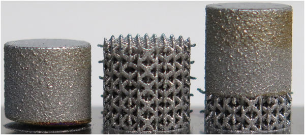
Utilization of lattice structures and their effects on build plate adhesion were evaluated as follows. Three 10-mm diameter cylinders, shown in Supplementary Fig. S6, were fabricated using identical laser parameters (P = 200 W, d = 55 µm, h = 105 µm, and t = 30 μs). The solid cylinder (left), built successfully for the first few layers until volumetric changes due to intermetallic formation and buildup of thermal stresses/strains could no longer be accommodated, resulting in the initiation of delamination. In contrast, the cylindrical lattice (middle) did not exhibit delamination at the build plate interface, and the entire cylinder was able to successfully build to completion. Finally, the solid cylinder built onto a lattice (right) showed no delamination at the build plate or lattice interfaces. Some external oxidation can be observed at the top and bottom of the cylinder, but otherwise printing on the lattice support appears to mitigate the challenges presented when building directly onto a build plate. As such, this approach can be leveraged for building larger and more complex 3D parts.
Scalable AM NiTi parts
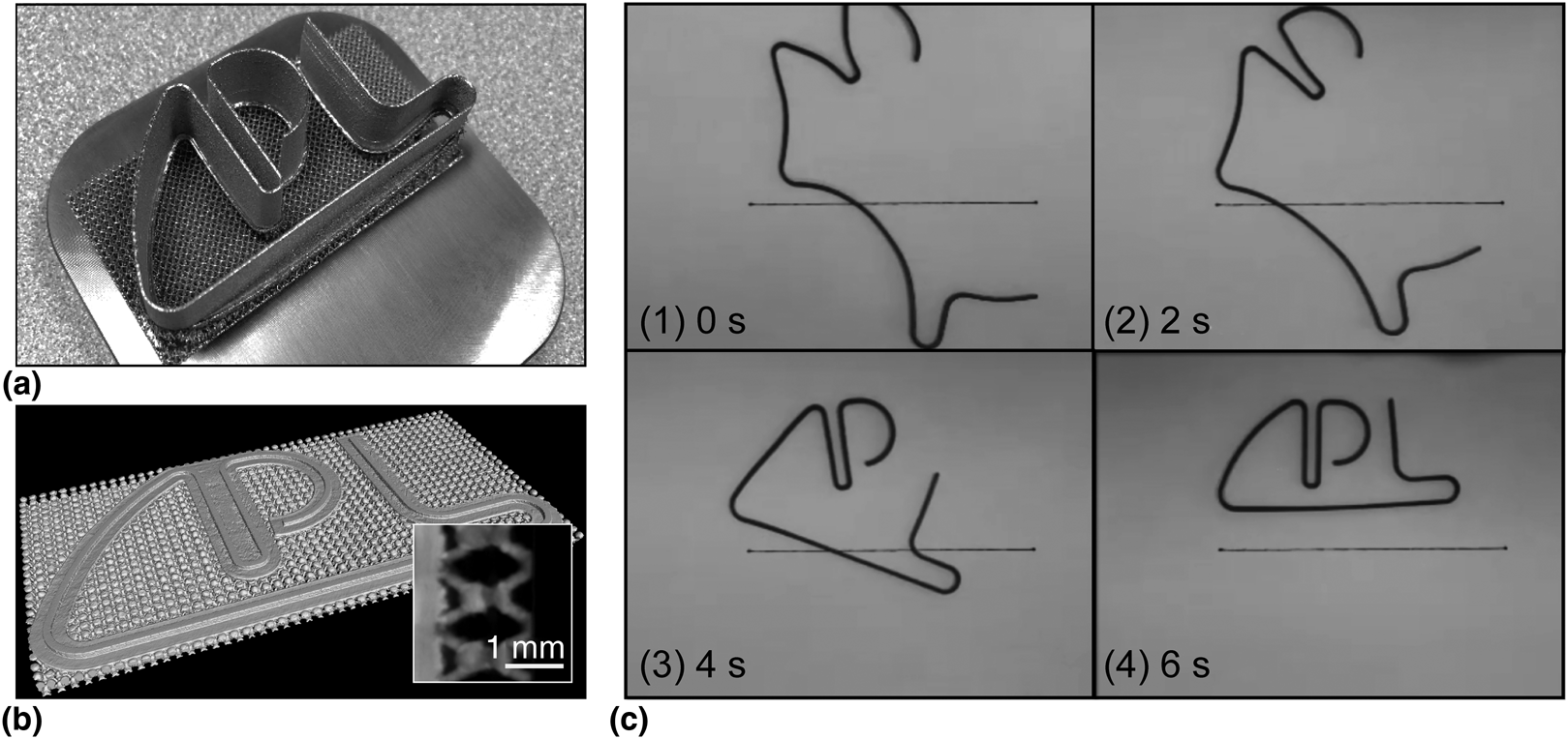
After analyzing melt pool stability and stoichiometry, processing parameters were down-selected and scaled to 3D builds. After mitigating build plate adhesion issues and introducing lattice support structures, a method for building complex 3D parts was determined. This approach was demonstrated by building a large, complex “APL” logo using the optimized processing parameters and lattice support on a Ti-6-4 build plate. Figure 4 demonstrates the success of the processing methodology, revealing a 65 mm × 32 mm × 20 mm part, built on a lattice, and without any cracking or delamination. Importantly, the entire part exhibits the desired shape memory effect after removal from the build plate. As can be seen in Fig. 4(b), the entirety of the part recovers simultaneously upon heat exposure, implying that the part has a relatively uniform composition and transformation temperature.
Proof-of-concept demonstration showing that the optimized processing parameters and lattice support approach translates to complex, large-scale, shape memory components. (a) APL logo part (65 mm × 32 mm × 20 mm) built on a lattice. (b) XRCT of logo/lattice interface after electrical discharge machining removal from the lattice; (inset) a higher magnification of logo/lattice showing with no sign of delamination. (c) Time stamps of deformed logo undergoing shape recovery upon heat exposure.

Conclusions
Although NiTi has been fabricated by AM previously, parts have been small and processing conditions have generally been determined based on only singular properties considerations (i.e., stoichiometry or cracking, but not both). To address these limitations with respect to scaling, we first examined the effects of laser energy density and build plate composition on melt pool stability and NiTi stoichiometry in final parts. After optimizing processing parameters in two dimensions, build plate reactivity and adhesion were identified as key issues preventing large-scale, 3D part fabrication. These issues were investigated by (i) tailoring energy parameters to decrease the melt pool and heat-affected zone volume, (ii) varying the build plate material, and (iii) utilizing a latticed support structure between the build plate and the desired part.
This work led to an understanding of how to optimally balance minimizing mixing near the substrate with achieving sufficient adhesion to accommodate strain due to the rapid quenching of the SLM process. Specifically, energy density was optimized, which controlled the size of the mixing zone and consequently decreased the probability of formation of deleterious intermetallic compounds. Additionally, by introducing a lattice raft, large-scale builds (with densities greater than 99.7%) demonstrating shape memory were realized. This fabrication approach appears to be a promising route for producing large-scale shape memory components with complex geometry, which is not possible using conventional manufacturing techniques.
Supplementary material
The supplementary material for this article can be found at: https://doi.org/10.1557/mrc.2019.134.
Acknowledgments
The authors thank Zachary Ulbig for assistance in running the Additive Manufacturing system utilized for this work. This work was supported by the JHU/APL Research and Exploratory Development Independent Research and Development Program.