I. INTRODUCTION
Ultra-wideband (UWB) radar techniques are used in a broad range of applications such as medical diagnosis and concealed objects detection. These microwave techniques often take advantage of the possible transmission of microwaves in materials that are totally opaque in the optical domain and of the maturity of active devices compared with the millimeter wave and terahertz fields. The capability of an imaging system to resolve targets depends on two parameters:
-
• The down-range resolution:
(1) $$\delta _r = \displaystyle{c \over {2B}}.$$
-
• The cross-range resolution [Reference Zhuge1]:
(2)
$$\delta _{cr} = \min \left[ {\displaystyle{c \over {0.7079B}},\lambda _c} \right]\displaystyle{R \over L},$$


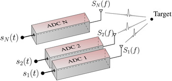
with c the wave velocity, B the absolute bandwidth, λ c the central wavelength, R the range of the focal point, and L the size of the radiating aperture. Thus, high-resolution imaging systems require the use of UWB hardware connected to a large amount of antennas, representing a substantial burden regarding its cost and complexity. Digital conversion-based architectures seem to be the most efficient solutions of imaging, being flexible enough to make them compatible with numerous scenarios of near- and far-field measurements. However, this technique requires the use of multiple analog-to-digital converters (ADC) and/or digital-to-analog converters (DAC) to transmit or measure waveforms simultaneously on an antenna array (Fig. 1).
In [Reference Carsenat and Decroze2], a compressive technique has been presented to achieve beamforming with UWB signals in a passive way. This method is based on the use of a passive multiplexer controlled by its input waveform, connected to an antenna array. This principle has been extended in [Reference Fromenteze, Decroze and Carsenat3], developing a compact compressive device and a new formulation of signal reconstruction. Another technique based on computational imaging has been introduced in [Reference Hunt4] and extended in [Reference Lipworth5], using a radiating aperture made of coupled resonators able to transmit signals in different directions of space simultaneously depending on the frequency. Both of these techniques are the same, exploiting the frequency diversity of a passive device to radiate orthogonal patterns at each frequency [Reference Fromenteze6]. A new study presented in the next section, is focused on the improvements brought by using several receiving chains connected to the compact compressive device introduced in [Reference Fromenteze, Decroze and Carsenat7]. The comparison between conventional and compressed beamforming is depicted to demonstrate the compressive capability of this technique and the modal diversity gain provided by using simultaneous measurements of independently coded waveforms.
Example of digital conversion-based architecture used for UWB beamforming and imaging.

II. MULTIPLE-PORTS COMPRESSIVE BEAMFORMING
A) Compressed acquisition theory
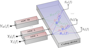
This paper is based on a compression from a set of N signals received by an antenna array into M signals after the propagation in a coding device, with M < N (Fig. 2)
Compression of a set of N signals received by an antenna array into M signals measured to compute digital beamforming.

.
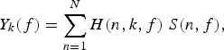
The expression of Y k (f), the signal compressed at the device's output k is defined in equation (3):
 $$Y_k (f) = \sum\limits_{n = 1}^N H(n,k,f) \;S(n,f),$$
with H(n, k, f) the compressive device transfer function between the ports k and n and S(n, f) the UWB signal received by the nth antenna. This compression corresponds to a generalization of the experiments presented in [Reference Carsenat and Decroze2, Reference Fromenteze, Decroze and Carsenat3, Reference Fromenteze, Decroze and Carsenat7, Reference Fromenteze, Decroze and Carsenat8], where the output was unique. In this paper, the use of multiple outputs is studied to evaluate the gain for beamforming performed with a large number of antennas. Following the compressive sensing theory, the sensing matrix [H] is sparse and must present a low level of correlation between its transfer functions, ensuring reduced inter-signal projections during the compressing process. Starting from the measured signals [Y(f)], the received waveforms [S(f)] are reconstructed to achieve digital beamforming using a pseudo-inversion of the matrix [H(f)] at each frequency. Thus, the estimation of the signals [S(f)] is:
 $$[S(f)]_{rec} = [H(f)]^ + [Y(f)].$$
[H(f)]+ is a pseudo-inverse computed by truncated singular value decomposition (tSVD) of [H(f)]. In this purpose, the matrix [H(f)] is factorized into three matrix for each frequency:
 $$\underbrace{{[H(f)]}}_{{N \times M}} = \underbrace{{[U(f)]}}_{{N \times N}} \underbrace{{[\Sigma (f)]}}_{{N \times M}} \underbrace{{[V(f)]}^{\dagger} }_{M \times M}, $$
with N the number of antennas and M the number of receiving chains. [U(f)] and [V(f)] are unitary matrices made of an orthonormal set of basis, weighted by the singular values ordered in the quasi-diagonal matrix [S(f)]. The conditioning of this linear application is defined by the following equation:
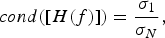 $$cond([H(f)]) = \displaystyle{{\sigma _1} \over {\sigma _N}}, $$
where σ 1 and σ N stand for the largest and the smallest singular values of [H(f)]. The condition number cond([H(f)]) relates the accuracy of the solution given by the pseudo-inversion. An ideally conditioned problem would involve a condition number of 1, meaning that all the singular values have the same significance and are not sensitive to the inversion. For an ill-conditioned problem, the lowest singular values can be set to zero to improve the accuracy of the pseudo-inversion, expressed as:
 $$[H(f)]^ {+} = [V(f)][\Sigma (f)]_{t}^{ - 1} [U(f)]^{\dagger}, $$
where
 $[\Sigma (f)]_t^{ - 1} $
is a quasi-diagonal matrix filled by {1/σ
1, …, 1/σ
β
, 0, …, 0}. All the remaining singular values must satisfy σ > β, with β a regularization parameter optimized empirically depending on the intrinsic conditioning of the problem and on the signal-to-noise ratio (SNR). By computing this pseudo-inversion frequency by frequency, the inverse matrix [H(f)]+ allows for a reconstruction of the waveforms received by the antenna array from the measured signals. Finally, radiation patterns C(θ, f) can be computed with the reconstructed signals [S(f)]. In the case of a far field approximation, the beamforming is computed in a conventional way by correlating the waveforms with plane waves:
 $$C(\theta, f) = \sum\limits_n^N S_{rec,n} (f) \,exp\left( {j\displaystyle{{2\pi f} \over c}dx_A (n - 1)\sin (\theta )} \right),$$
with dx A the inter-antenna spacing and θ the beamsteering direction. In the next section, this principle is applied to a compact device connected to an antenna array to illustrate the beamforming improvement compared with conventional beamforming techniques used with the same amount of receivers.
B) Application to a compressive device
1) STUDY OF THE SINGULAR VALUES
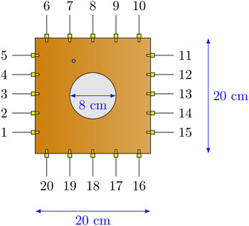
A two-dimensional chaotic cavity introduced in [Reference Fromenteze, Decroze and Carsenat7, Reference Fromenteze, Decroze and Carsenat8] is used as a passive multiplexer (Fig. 3).
Planar compressive device connected to 20 SMA ports.

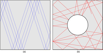
This device is a 0.65 mm thick microwave substrate RT/duroid 6006 with a hole engraved on its top conductor. Twenty SMA ports are regularly connected to its edges, with small distance variations to break periodicity. Despite its simplicity, this microwave device presents very useful properties linked to the association of regular and convex boundaries delimiting the propagation medium [Reference Draeger, Aime and Fink9, Reference de Rosny, Tourin and Fink10]. These properties can be illustrated by representing the field in a cavity by its equivalent plane wave spectrum. The path followed by a plane wave can be replaced by a ray bouncing on the cavity's boundary (Fig. 4).
Comparison between a regular and a chaotic cavity: propagation of a ray, starting from the same initial conditions.

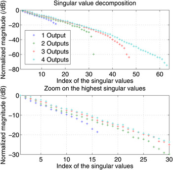
Starting from the same initial conditions, a ray in a chaotic cavity tends to fill the entire space after several reflections, compared with a regular cavity, where it is focused into particular areas. Furthermore, a slight modification of the initial conditions of a ray in a chaotic cavity can have a significant impact in the way it propagates. Thus, even with a limited frequency diversity, which represents the support of the signals compression, these properties help to decrease the correlation level between the device's transfer functions by preventing the modal degeneration. The aim of this study is to demonstrate using several outputs, simultaneously the better reconstruction of the signals when a large number of antennas are connected to the compressive device. Thus, the transfer function between 16 inputs and 4 outputs are measured in the 2–4 GHz frequency range (300 points) to evaluate the singular value spectrum according to the number of connected outputs (Fig. 5).
Normalized magnitude of the singular values depending on the number of outputs connected to the compressive device.

More information is measured when new outputs are connected, leading to higher singular values and improved conditioning for a given regularization parameter. This device can be adapted to beamforming by connecting an antenna array to the compressive device's ports. Exploiting the larger number of independent states measured on the 4 outputs of this component, the equalization of its transfer functions is performed to estimate the waveforms received by the connected antennas.
2) COMPRESSED BEAMFORMING
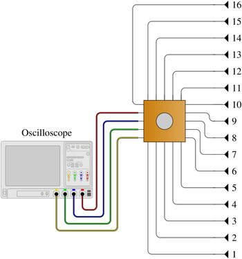
In conventional digital beamforming as many receivers as antennas are required. With an equal number of receiving chains, compressive beamforming can be performed with a larger number of antennas connected to the passive multiplexer. For example, 16 antennas are connected to the chaotic device and compressed into 4 waveforms (Fig. 6).
Compressive beamforming system connected to 16 antennas, and to 4 independent receiving chains. In the study of conventional beamforming, 4 antennas are directly connected to the receiver's outputs, while maintaining the same inter-antenna spacing.

The beamforming capabilities of this system are compared with a conventional digital beamforming array made of 4 elements. These experiments are simulated by Matlab programs using the device's measured transfer functions in the 2–4 GHz frequency range. In both cases, the inter-antenna space is set to
 $$dx_A = 0.7\displaystyle{c \over {f_{mean}}} = 7\,{\rm cm}. $$
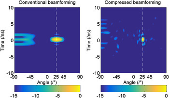
Figure 7 depicts the results obtained, when beamsteering is in the 25° direction, for a conventional system made of 4 elements and for a compressive system connected to 16 antennas. In both cases, the antennas are isotropically radiating and mutual coupling is not considered. The radiation patterns computed with equation (8) are converted from the frequency to the time domain using an inverse Fourier transform.
Comparison of the time-domain radiation patterns computed for a conventional beamforming with 4 antennas compared with a compressed beamforming of 16 antennas connected to 4 receivers via the compressive device. The beamsteering is performed in the 25° direction.

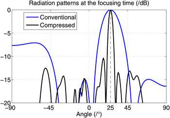
This figure shows that using the same number of receiving chains and inter-antenna space, the compressive technique allows for a thinner formed beam, since the equivalent radiation aperture is wider and appropriately sampled. Furthermore, the grating lobes observed with the conventional system are mitigated by the compressive device, due to a statistical cancelation of the off-axis frequency components [Reference Fromenteze, Decroze and Carsenat7]. The time required for the computation of the tSVD pseudo-inverse was less than 3.5 × 10⁻² s on a computer with a 3.3 GHz 6-core processor and 8 Gb of RAM and only needs to be done once, since the compressive device's transfer functions are stationary. The estimation of the received signals is then calculated in less than 2 × 10⁻³ s. Radiation patterns are extracted at the focusing time t = 0 ns and presented in Fig. 8.
Radiation patterns extracted at the focusing time from Fig. 7.

3) SIMULTANEOUS MEASUREMENTS AND BEAMFORMING
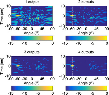
The next part of this study is focused on the impact of the number of connected outputs to achieve beamforming. An example is depicted in Fig. 9 to show the improvement provided by increasing the number of outputs for a beamsteering in the −60° direction.
Improvement in beamforming depending on the number of connected outputs, for a beamsteering in the −60° direction.

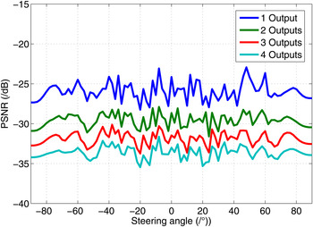
In this example, the level of the point spread function sidelobes tends to go down when the number of connected outputs increase, meaning that new useful information is measured and decompressed giving better estimations of the waveforms received by the antennas. Thus, the main lobe peak to integrated sidelobe level (peak signal-to-noise ratio (PSNR)) is defined to determine the efficiency of the reconstruction for each beamsteering direction Φ, depending on the number of connected outputs:
 $${\rm PSNR}(\Phi ) = - 10\mathop {\log} \nolimits_{10} \left( {\displaystyle{{\sum\limits_{\theta} \sum\limits_{t} \left[ { \vert C_{\Phi} (\theta, t) \vert - \vert C_{{\Phi}, idl} (\theta, t) \vert} \right]} \over {n_{\theta} n_{t}}}} \right),$$
with C Φ (θ, t) the time-domain radiation pattern computed with the compressive technique and C Φ,idl (θ, t) the equivalent ideal radiation pattern calculated by plane wave projections over the position of the 16 antennas, when beamsteering is in the direction Φ and considering a full bandwidth illumination. Finally, n t and n θ are the respective numbers of time-domain and angular-domain samples. According to the application, the trade-off between quality of the reconstruction and complexity of the associated hardware can be chosen. The computed results are gathered in Fig. 10.
Integrated sidelobe level depending on the amount of connected outputs and of the steering angle.

As expected, the quality of the beamforming directly depends on the number of measured signals from the compressive device, allowing for better reconstruction of the received signals.
Thus, this principle has been theoretically validated for far field beamforming using measured transfer functions of a compressive device. An experimental setup has also been implemented to present results of source localization and radar imaging.
III. EXPERIMENTAL VALIDATION
A) Source localization
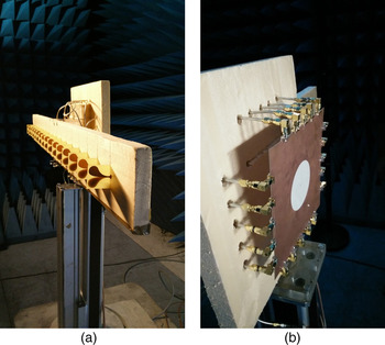
A first experimental setup developed for the localization of an antenna in space is introduced. A linear array made of 16 antipodal Vivaldi antennas inspired from [Reference Zhuge and Yarovoy11] is connected to the ports of the compressive device (Fig. 11):
Antenna array connected to 16 ports of the compressive device.

The experimental validation is achieved in the same conditions as in the theoretical study, in the 2–4 GHz band and with an inter-element spacing of 7 cm. Thus, the total size of the radiating aperture is D = 105 cm, imposing a far field distance of:
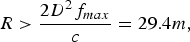 $$R \gt \displaystyle{{2D^2 f_{max}} \over c} = 29.4m,$$
with c the speed of light and f max = 4 GHz. Limited by the maximum length of the semi-anechoic chamber used for this experiment, back-propagation algorithms are implemented since the Fraunhofer approximation cannot be applied in such conditions. To limit the computation time, a range migration algorithm is computed using the following expression:
 $$I(x,y) = \int_{k_x} \int_{x_A} S_{rec} (x_A, f)e^{jk_y (k,k_x )y} e^{jk_x x_A} dx_A e^{ - jk_x x} dk_x, $$
where S rec (x A , f) is the matrix of waveforms reconstructed on the antennas at positions x A . For the sake of computing speed, this algorithm can be fully computed using Fast Fourier transforms and a Stolt interpolation [Reference Lopez-Sanchez and Fortuny-Guasch12].
A transmitting antenna connected to an arbitrary waveform generator is set in the semi-anechoic chamber to be localized. A chirped signal is generated in the 2–3 GHz range for the characterization of the compressive device channels and radar measurements so that the pseudo-inversion presented in equation (4) compensates for dispersion. Four signals are measured by an oscilloscope connected to the 4 remaining ports of the compressive device, as depicted in Fig. 6. Measuring a set of compressed signals, an estimation of the waveforms on the antennas is computed using equation (4). Two scenarios are presented in this study.
1) FIRST SCENARIO OF LOCALIZATION
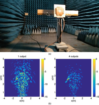
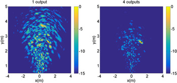
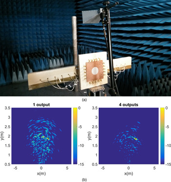
For this first scenario, the transmitting antenna is set on the left of the reception array. The result of the reconstruction is depicted in Fig. 12 from 1 to 4 measured signals to illustrate the improvement provided by the measurement of multiple compressed signals.
Experimental setup of the first localization measurement and associated results. Black circles on the pictures represent the measured position of the antenna.

A good agreement between the measured and the computed positions of the transmitting antenna is observed using this compressive approach. Furthermore, exploiting the enhanced modal diversity of several compressed signals; lower level sidelobes are noted. The peak-to-sidelobe ratio (PSLR) is given in each case to analyze this enhancement according to the following equation:
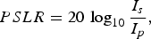 $$PSLR = 20\,\log _{10} \displaystyle{{I_s} \over {I_p}}, $$
where I s , stands for the maximum sidelobe value and I p , the peak value of the main lobe, both extracted from the radar image computed in each scenario using equation (12). Thus, in the case of a single output, the PSLR is −0.75 dB and is reduced to −7.3 dB in the case of 4 measured signals. The second scenario of localization is studied, moving the transmitting antenna to the right of the receiving aperture.
2) SECOND SCENARIO OF LOCALIZATION
For this second measurement, the transmitting antenna is set at another location.
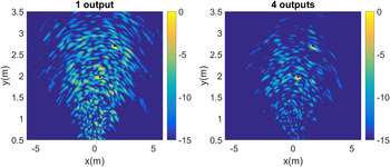
Once again, a set of 4 compressed signals is measured to compute the position of the radiating element in space, showing a good agreement with its measured location (Fig. 13). The PSLR of the single output case is −1.46 dB, while using 4 measured signals the PSLR is reduced to −9.6 dB. In both cases, this compressive system localized the radiating antenna in space, exploiting the performance of a 16 antenna array by the measurement of only 4 signals. The experimental setup is then modified to achieve radar imaging, setting the transmission antenna above the receiving aperture.
Results of the second localization measurement. Black circles on the pictures represent the measured position of the antenna.

B) Radar imaging
In this new setup, a first measurement without targets is performed to consider the coupling between the transmission and reception antennas. These 4 signals measured on the oscilloscope ports are subtracted from subsequent measurements to consider only the coded reflexions of targets.
1) FIRST SCENARIO OF RADAR IMAGING
A metallic cylinder is set in front of the compressive radar system, as depicted in Fig. 14. A new measure of 4 waveforms on the compressive device's outputs allows for an estimation of the signals on the reception antennas and the computation of a radar image using a range migration algorithm (considering forward and backward propagations).
First scenario of radar imaging with a single target. The black dot marks the measured position of the cylinder.

The measured and computed positions are in agreement for this first scenario of radar imaging. Exploiting more degrees of freedom measured in the 4 compressed signals, the estimation of the waveforms on the antennas, and therefore the radar image, is better than that of a single measured signal, enhancing the PSLR from −2.23 to −8.48 dB. In the next part, a second scenario of radar imaging is presented using two metallic cylinders.
2) SECOND SCENARIO OF RADAR IMAGING
In this case, two cylinders of radiuses 15 and 12 cm are set in front of the imaging system in the semi-anechoic chamber, the thinner being closer to the receiving aperture. The associated results are presented in Fig. 15.
Second scenario of radar imaging with two targets. The black dots mark the measured positions of the cylinder.

Once again, the reconstruction of the targets positions is in agreement with the measured ones. A PSLR of −2.18 dB is computed in the case of a single output measurement and is reduced to −4.71 dB when 4 signals are measured.
IV. CONCLUSION
The technique of compressive multiplexing is introduced in this paper which allows for an optimization of UWB imaging systems. Using a very simple passive microwave device, this study demonstrated the compression of 16 waveforms received by an antenna array into 4 measured signals. This work is an extension of previous studies [Reference Carsenat and Decroze2, Reference Fromenteze, Decroze and Carsenat3, Reference Fromenteze, Decroze and Carsenat8] and it proposes a relaxation of the constraints of the compressive device's size and design and allows for controlling more radiating elements compared with former experiments based on single output systems. Theoretical and experimental validations have demonstrated the localization performance of emitters and targets, exploiting the enhanced modal diversity measured in 4 compressed signals.
Using this compressive approach, being based on the exploitation of modal diversity in a reverberating cavity, improved estimations of compressed waveforms could be obtained by increasing the absolute operating frequency bandwidth or by using a larger scattering medium able to carry more modes [Reference Fromenteze13]. Iterative reconstruction method such as a regularized matching pursuit algorithm [Reference Fromenteze, Kpre, Carsenat and Decroze14] could also be applied to improve the waveforms estimation and the radar images computation.
ACKNOWLEDGEMENTS
The authors would like to express their gratitude to the anonymous reviewers for their careful reading of this manuscript and their many insightful comments and suggestions.
 Thomas Fromenteze received his Ph.D. in 2015 from the University of Limoges, France. He is presently a Postdoctoral Researcher with the CMIP, Duke University, USA. His main research interests are ultra-wideband microwave imaging systems, wave propagation in complex media, and inverse problems. He received the EuRAD Young Engineer Prize during the European Microwave Week, 2015.
 Ettien Lazare Kpré was born in Ivory Coast in 1988. He received his degree in Telecommunication Engineering at Institut Supérieur d'Electronique et des Réseaux Télécoms in Morocco (Casablanca) in 2012. After graduation, he joined Limoges University where he received his M.S. in Microwave Engineering in 2014. He is now a Ph.D. student at Xlim Institute Research. His main research interests include electromagnetic signal processing, MIMO radar, passive microwave devices, image reconstruction.
 David Carsenat received his Ph.D. degree in Telecommunications Engineering from the University of Limoges, Limoges, France, in 2003. Since October 2003, he has been an Associate Professor at the 3IL School of Engineering and does his research in the Wave and Associated Systems (OSA), Department of XLIM Research Institute, University of Limoges. His research relates to wireless propagation channel, MIMO systems, digital wireless communications, and electromagnetic computing.
 Cyril Decroze received his Ph.D. degree in Telecommunications Engineering from the University of Limoges, Limoges, France, in 2002. He is presently an Associate Professor with the XLIM Research Institute, University of Limoges, France. Since 2006, he has been in charge of the wireless systems activity in the Wave and Associated System Department at XLIM institute. His field of research concerns multiple-antennas systems and associated processing for telecommunications and radar imaging.