Introduction
Ultra-wideband (UWB) communication system has received extensive attention and achieved development because of its advantages in short-range wireless communication and indoor positioning [Reference Yang and Giannakis1, Reference Liang, Chiau, Chen and Parini2]. UWB antennas [Reference Nikolaou and Abbasi3–Reference Shan and Shen5] and UWB filters [Reference Chu, Wu and Tian6, Reference Xu, Wu, Kang and Miao7] are customarily designed separately as two devices in the RF front-end. However, with the development of wireless, the design of independent devices cannot meet the current requirements for miniaturization and integration of system. Therefore, it is interesting to study the filtering function of antenna for the miniaturization and integration of RF front-end, which has great advantages over the traditional antenna.
There are a number of papers on filtering antenna using shorting pins [Reference Wong, Huang, Mao, Chen and Chu8], parasitic structures [Reference Hu, Tang, Li, Wang and Li9, Reference Ding, Zhang, Zhang, Pan and Xue10], or resonant elements [Reference Li, Zhao, Tang and Yin11, Reference Amdaouch, Aghzout, Naghar, Vazquez Alejos and Ait Ahmed12] to introduce transmission zeros to improve the sideband selectivity and realize filtering characteristics. Although the sideband selection characteristics of these antennas are improved, the out-of-band suppression is poor. In addition, this method is mostly used in the design of narrowband filter antennas, and the application effect of wideband filter antennas is not ideal.
Connecting the antenna and the filter directly is another common method to achieve filter antenna design [Reference Sahoo, Gupta and Parihar13–Reference Tang, Wen, Wang, Li and Ziolkowski17]. The concept of this design method is to connect the antenna and the filter directly, and the antenna serves as a load port of the filter. The output and input ports of the antenna and filter are 50 Ω at the center frequency, but this does not guarantee that the antenna input impedance in the entire wideband is 50 Ω, that is, ZL ≠ Z 0 (ZL is a purely resistive load, Z 0 is characteristic impedance) [Reference Yang, Liu, Xi, Du, Tan and Zhang18]. Therefore, the broadband filter and the antenna will not match in some frequency bands after being connected.
For the filtering characteristics of the antenna, we have also done some exploration and research in the published papers [Reference Yang, Xi, Zhao, Wang and Shi19–Reference Yang, Xi, Wang, Zhao and Shi21], but these studies are mainly aimed at improving the sideband selectivity and the impedance characteristics of slot antennas. This letter mainly studies the good filtering properties and in-band impedance properties of the monopole antenna. The filtering characteristics are obtained by designing a feeding line with filtering characteristics and connecting with a monopole antenna. Firstly, a circular monopole antenna with UWB characteristics is presented. Secondly, a bandpass filter with circular-stub-load is proposed. To obtain the same resonant mode as the circular monopole antenna, the branch loading of the filter adopts the same structure as the circular monopole antenna. Finally, the monopole antenna obtains filtering characteristics and better in-band impedance characteristics. At the same time, other branch-loaded structure filters and monopole antenna combinations are also discussed. Based on this comparison, it is found that the branch-loaded filter with the same structure as the monopole antenna can obtain better filtering characteristics and in-band impedance characteristics.
Antenna design
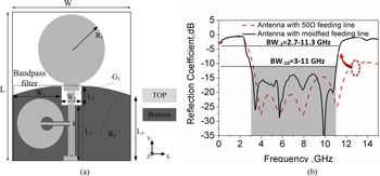
The geometry of the final circular monopole filtering antenna is presented in Fig. 1(a). The dimensions of the proposed design are 30 × 25 mm2, which is designed on Rogers 4350 substrate with the relative dielectric constant of 3.38 and a thickness of 1.524 mm. The antenna is composed of a circular radiation patch with a radius of R 1 = 10.5 mm, a compact filtering feeding line, and a notched arc-shaped ground structure. The arc-shaped ground is designed to reduce the damage to the current caused by the two right-angled reflective surfaces in the rectangular floor and to improve the impedance of the antenna and the fidelity of the time-domain signal. The rectangular open slot on the curved ground is used to improve the impedance characteristics of the monopole antenna at high frequencies.
(a) Geometry of the proposed antenna, (b) reflection coefficient of the antenna before and after improvement.

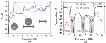
Figure 1(b) illustrates the reflection coefficient of the circular monopole antenna before and after improvement. As can be seen from Fig. 1(b), the reflection coefficient of the circular monopole antenna is relatively flat in the passband, and there is no obvious fading phenomenon in the low-frequency sideband. The high-frequency changes are also relatively gentle, and the sideband selectivity characteristics are poor. Therefore, to improve the sideband selectivity characteristics of circular monopole antenna and study the different branch loading structures, a circular-stub-load multi-mode resonator (MMR) bandpass filter is designed, as shown in Fig. 1.
Different from the antenna in [Reference Sahoo, Gupta and Parihar13, Reference Sahu, Singh, Meshram and Singh14, Reference Tang, Wen, Wang, Li and Ziolkowski17], the antenna in this design does not need any matching network or 1/4 wavelength microstrip line between the radiation patch. In this design, the same structure of the antenna circular radiating patch is designed as the stub loading, so that the filter and the circular monopole antenna have the same resonance mode, thereby reducing the mismatch problem in the process of combining two identical resonance modes, as seen in Fig. 2.
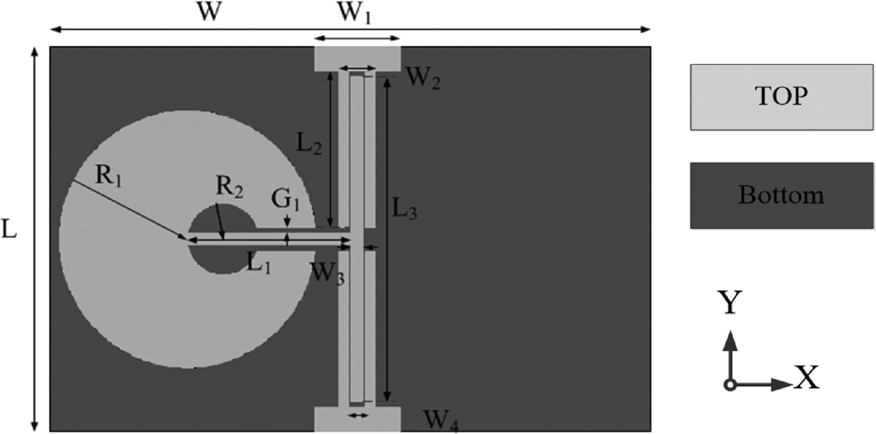
Structure of the circular-shaped UWB bandpass filter.

As is observed in Fig. 2, the MMR bandpass filter is composed of a couple of quarter wavelength inter-digital coupled-line and a circular-shaped MMR at the center. The circular-stub-load MMR selected in this letter has the same structure as the radiating patch, which is different from the rectangular and sector loading resonator in the literature [Reference Chu, Wu and Tian6, Reference Xu, Wu, Kang and Miao7]. The circular loading is closer to the resonance mode of the circular monopole antenna, which is beneficial for enhancing the resonance mode of the UWB filter antenna and improving its in-band impedance characteristics. Since the branch-loaded MMR is a center-symmetric structure, its resonance characteristics may be studied through odd- and even-mode.
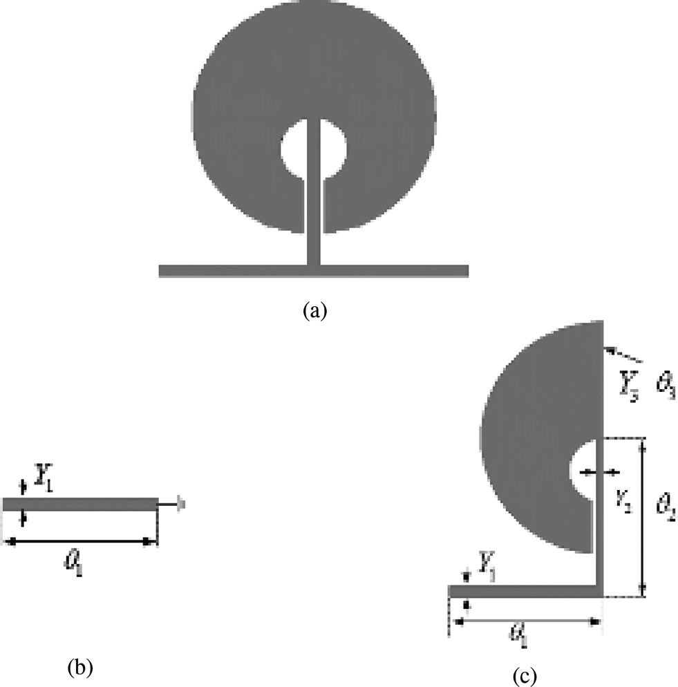
Under odd-mode conditions, the symmetrical plane of the resonator can be regarded as an electric wall and the plane of symmetry is shorted to the ground, as presented in Fig. 3. The even-mode input admittanceY odd can be expressed as:

where Y 1 and θ 1 represent the characteristic admittance and electrical length in the equivalent circuit. According to the resonance conditions of the resonator, under the condition of Y odd = 0, it is an odd-mode resonator, and the odd-mode resonance frequency f odd can be expressed as:

(a) Circular resonator, (b) odd mode, (c) even mode.

where n = 1, 2, 3, ⋅ ⋅ ⋅ , c is the speed of light, ɛeff is the effective dielectric constant, L 1 is the length of the half-wavelength transmission line, β is the propagation constant of electromagnetic waves in the microstrip line, and λ g is the waveguide wavelength in the microstrip line. As seen from Fig. 3 and equation (1) that the odd mode does not contain the stub load electrical length, so the odd mode resonance frequency has nothing to do with the stub load.
For the even mode as shown in Fig. 3(c), the symmetry plane is regarded as an open circuit, with no current flows. The input admittance Yeven is expressed as [Reference Zhu and Chu22, Reference Pozar23]:

In the resonance condition of the even-mode Yeven = 0, the resonance frequencies of the even mode can be expressed as formula (4):

For simple analysis, when Y 3 = 2Y 2, formula (4) can be further simplified as:

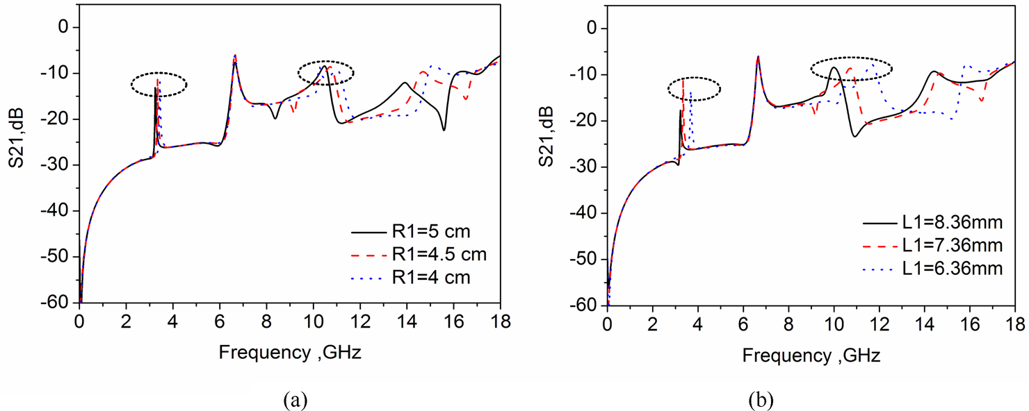
It can be seen from equation (5) that under the condition that the electrical lengths of the horizontal microstrip line and the stubs are constant, the resonant frequency of the even mode can be regulated by the electrical lengths θ 2 and θ 3 loaded by the circular stubs. Therefore, by regulating the length L 1 of the stub and the radius R 1 of the circular stub-loaded resonator, the composition of the odd and even modes and the influence on the resonance frequency can be analyzed.
Figures 4(a) and 4(b) show the response characteristic curves of different circular load radius R 1 and resonator branch length L 1 respectively. It can be seen from Figs 4(a) and 4(b) that there are three resonance modes in the entire UWB frequency band (3.1–10.6 GHz) under weak coupling conditions. The resonant frequency of the circular branch-loaded structure coincides with the main resonant frequency of the radiating antenna. When the size of the stub length L 1 and the circular loading radius R 1 is reduced, the first and third even-mode resonance frequencies move toward high frequencies, while the odd-mode resonance frequencies are unchanged. Therefore, by adjusting the electrical length of the intermediate loading stub under the condition of certain impedance, the adjustment of the resonant frequency in the even mode can be achieved without changing the odd mode in the resonator.
Effect of the radius of a circular resonator R 1 and length L 1 on the resonant frequency.

In summary, comparing the two resonant frequencies of odd mode and even mode, the resonant frequency is related to the corresponding admittance and electrical length. Under the condition of constant admittance, by adjusting each position and electrical length in the resonator, the resonance frequency can be adjusted to a frequency band that meets the requirements of UWB antenna resonance consistency.
In addition, the operating working band of the UWB bandpass filter is 3.1–10.6 GHz, which requires strong port coupling, so another important design is the filter port coupling design. In this design, the interdigital coupling structure is designed as seen in Fig. 2. By applying the interdigital coupling structure at two sides to the proposed MMR, good passband and out-of-band suppression performance of the bandpass filter are realized, as seen in Fig. 5(a). By combing the weak coupling resonator loaded with circular branch and the strongly coupled finger port and optimized by electromagnetic simulation software CST, good bandpass filtering is obtained as shown in Fig. 5(b). It can be seen from Fig. 5(b) that the −10 dB bandwidth of the bandpass filter is 2.75–10.8 GHz, which meets the working frequency band of UWB of 3.1–10.6 GHz. The filter shows better flatness and lower loss in the passband, and S 21 is −0.15 dB. In addition, the filter produces two transmission zeros on both sides of the S parameter, which helps to enhance the sideband selection characteristics of the filter, as shown in Fig. 5(b). In this design, the optimum size of the filter is optimized as follows: L = 16 mm, W 1 = 3.6 mm, W 2 = 1.5 mm, L 1 = 6.68 mm, L 2 = 6.5 mm, L 3 = 13.5 mm, W = 25 mm, W 3 = 0.5 mm, W 4 = 0.7 mm, R 1 = 10.4 mm, R 2 = 1.5 mm, G 1 = 0.25 mm.
(a) S-parameters of the MMR and interdigital coupling structure, (b) S-parameters of the UWB bandpass filter.

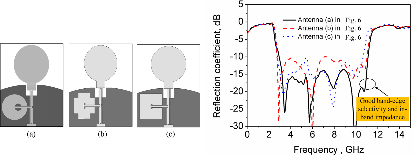
Figure 6 illustrates the structure and simulation results after the combination of filter elements and radiation antennas with different branch loading structures. It can be seen from Fig. 6 that compared with other structures the feeding line with circular branch loading structure not only improves the sideband selectivity characteristics but also has better in-band impedance characteristics. From Fig. 5(b), it can also be seen that the three resonant frequency points of the well-designed circular filter match well with the main resonant frequency points of the antenna, which is helpful to reduce the mismatch problem after the filter and antenna cascade. The final size of the filter antenna is 30 × 25 mm2. The detailed structure size of the proposed filter antenna in Fig. 1(a) is L = 16 mm, L 1 = 11.1 mm, L 2 = 3.8 mm, L 3 = 13.1 mm, W = 25 mm, W 1 = 3.6 mm, W 2 = 1.5 mm, R 1 = 10.68 mm, R 2 = 20.2 mm.
Structure and the reflection coefficient of the antenna with three different branch loading structures. (a) Circular, (b) flower shape, and (c) rectangle.

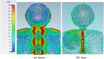
The current distribution of the circular monopole filter antenna before and after the improvement at the 12 GHz (out-of-band) frequency point is illustrated in Fig. 7. According to Fig. 7(a), the current of high-frequency at 12 GHz is distributed around the arc-shaped ground and radiation patch of the circular monopole antenna, which will still generate more radiation. As shown in Fig. 7(b), the current of the improved filter antenna at the radiation patch and ground edge was significantly reduced, and the introduction of the filter structure increased the ability to suppress the currents of out-of-band high frequency. Finally, the good suppression of the out-of-band frequency band is achieved.
Current distribution at 12 GHz of the filtering antenna before and after improvement, (a) before, (b) after.

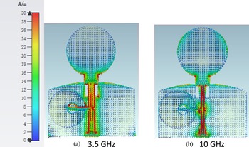
Figure 8 shows the current distribution of the filter antenna at the transmission zero point of 3.5 and 10 GHz. It can be seen from the figure that the introduction of the filter structure can have a strong current distribution in the upper and lower sideband frequency points of the UWB antenna, and can generate strong resonance, which has a direct effect on the improvement of the sideband selection characteristics of the antenna.
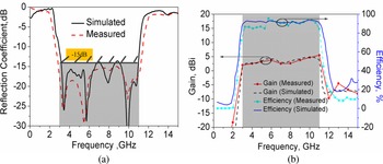
Simulated and measured reflection coefficient and gain of the proposed design. (a) Reflection coefficient, (b) gain and efficiency.

Results and discussions
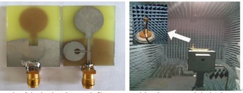
To further verify the effectiveness of the circular monopole filter antenna, the design was processed and tested. The real picture and microwave test environment are illustrated in Fig. 9. Figure 10 illustrates the measured and simulated reflection coefficient, gain, and radiation efficiency of the final design. The measured results of the reflection coefficient are consistent with the simulation results, which are lower than −15 dB in the whole frequency band. As is shown in Fig. 10(a), the measured reflection coefficient of −10 dB bandwidth is 2.9–11.1 GHz (117%), which is slightly increased compared to the simulated result 3–11 GHz (114%). This is mainly due to some matching and dielectric constant errors. The measured and simulated gain of the proposed design is illustrated in Fig. 10(b). The measurement and simulation results show that the gain and radiation efficiency of the filter antenna also show good sideband selection characteristics and out-of-band suppression. It is noticed that the proposed design has steady gains (3 ± 1.5 dBi) in working band, but sharply decreases at the lower and upper edges. From Fig. 9, it is observed that the simulated and measured radiation efficiency is above 85%.
Photography of circular-shaped monopole filter antenna and the microwave anechoic chamber.

Simulated and measured reflection coefficient and gain of the proposed design. (a) Reflection coefficient, (b) gain and efficiency.

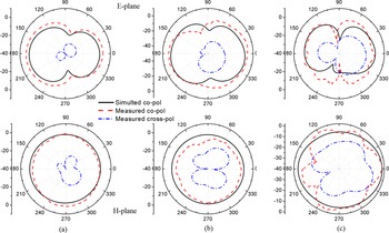
The measured and simulated radiation patterns of the filtering antenna at 3.1, 6, and 10 GHz are shown in Fig. 11. Analyzing Fig. 11, it is obvious that the proposed design shows good omnidirectional radiation patterns in the entire band and the measured results are better aligned with the simulated results. It is also observed that the quasi-omnidirectional of the H-plane radiation patterns is generally good and with low cross-polarization values at 3.1 and 6 GHz. At a higher frequency of 10 GHz, the radiation patterns become imbalanced with some nulls, which is caused by the imbalance of current distribution in the arc-shaped ground at higher frequencies. This is mainly due to the fact that the electrical height of the high-frequency monopole part has exceeded half of the frequency wavelength, so it is difficult to keep the mode stable.
Measured radiation patterns at (a) 3.1 GHz, (b) 6 GHz, and (c) 10 GHz.

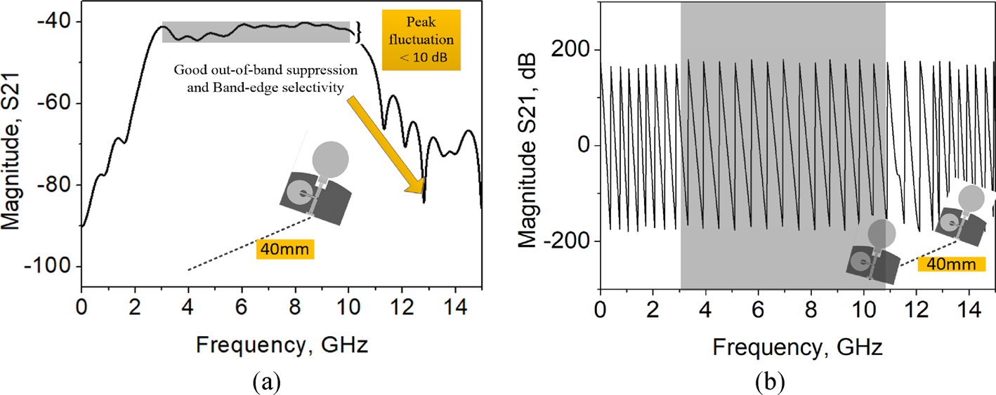
For UWB antennas, their time-domain characteristics are also very important. To verify its performance in the time domain, two identical antennas were placed face-to-face with a distance of 40 cm, and the group delay, receive signals, and transfer functions (magnitude S 21 and phase S 21) were studied respectively. To minimize the signal distortion caused by signal bandwidth and impedance mismatch, the fifth-order Gaussian pulse is used to excite the proposed antenna. The signal expression is as follows:

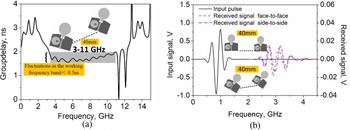
where C is the amplitude parameter spectral density suggested by FCC and σ = 51 ps. Figure 12 shows the group delays and the received waveforms of the filtering antenna. It is manifest from Fig. 12(a) that the delay change of the working band group is smaller within ±0.25 ns. As shown in Fig. 12(b), in both face-to-face and side-to-side cases, the receiving signal of the filter antenna in this design has a small ring distortion at the receiving end. In addition, the amplitude and waveform fidelity of the received signal are relatively close in both cases of the filter antenna. It can also be seen from Fig. 13 that the antenna has good amplitude flatness and phase continuity in the passband, and has obvious amplitude attenuation and phase discontinuity in the band-edge. The above results show that the proposed antenna not only ensures good performance in the passband but also shows a good suppression effect in the time domain.
(a) Group delays of the antenna, (b) input and received pulses.

Simulated transfer function. (a) Magnitude S 21, (b) phase S21.

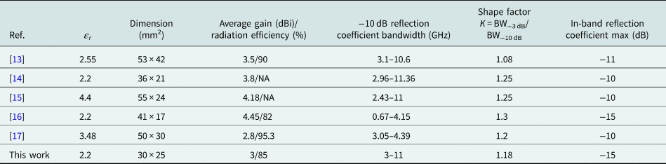
To highlight the novelty of the proposed design, a comparative study of some other competitive filtering antennas is shown in Table 1. To effectively evaluate the band-edge selectivity of the UWB antenna, a shape factor K is defined, where BW−3 dB and BW−10 dB are −3 and −10 dB bandwidths of the return loss, respectively. The ratio of the −3 dB bandwidth to the −10 dB bandwidth is close to 1, indicating the better band-edge selectivity of the UWB antenna. Comparative analysis illustrates that the proposed design has better sideband selectivity and impedance matching. The comprehensive comparison results show that the proposed design has obvious advantages in dimension, sideband selection, and in-band impedance matching in the passband.
Comparison with some competitive reported antennas

Conclusion
In this paper, a compact circular monopole filtering antenna with improved sideband selectivity and in-band impedance using a circular-stub-load resonator is proposed. To obtain better sideband selection characteristics and reduce the mismatch problem caused by the introduction of the filter, a branch-loaded filter with the same resonance mode as the antenna radiation patch is designed. Furthermore, other branch loading structures are also discussed. The experimental results also show that the proposed design exhibits good passband characteristics, sideband selection characteristics, and out-of-band suppression in both the time domain and frequency domain. Owing to its compact dimensions and good performance, the proposed design can be advantageously applied in the point to point UWB communications or high-resolution radar applications.
Acknowledgements
This work was supported by the Natural Science Foundation of Shannxi Province, China (Grant No. 2021JQ-710; Grant No. 2021GY-049; Grant No. 2020GY-065) and in part by Xi'an Science and Technology Plan Project under Grant 2021JH-06-0038, 2020KJRC0102, 2021-R-51.
 Hailong Yang received the B.S. in communicating engineering from Heze University, Heze, China, in 2012, and M.S. and Ph.D. degrees in communicating engineering from Xi'an University of Technology, Xi'an, China, in 2015 and 2019. He joined the faculty of Electronic Engineering Department, Xi'an University of Posts & Telecommunications, in 2019. His research interests include wave propagation and antenna design.
 Jinsheng Zhang was born in 1980. He received the M.S. degree in control science and engineering from the Xi'an Research Institute of High-Tech, Xi'an, China, in 2005, and a Ph.D. degree in Control Science and Engineering from the Xi'an Research Institute of High-Tech, Xi'an, China, in 2009. He is currently a professor at the Department of Navigation, Guidance and Simulation, Xi'an Research Institute of High-Tech, Xi'an, China. His recent research areas include flight vehicle guidance, control and simulation, and geomagnetic navigation.
 Xuping Li received the B.S., M.S., and Ph.D. degrees in electronic science and technology from Xidian University, Xi'an, China, in 2007, 2010, and 2018, respectively. From 2006 to 2018, he worked in the microwave engineering division of 206 Chinese weapons, where he was the director designer of antenna system, assistant minister, and director of antenna room. He joined the faculty of Electronic Engineering Department, Xi'an University of Posts & Telecommunications, in 2018. His research interests include phased array radar and antenna design.
 Rongji Li (M’2010) was born in 2000. He is currently an undergraduate at Xi'an University of Posts & Telecommunications, Xi'an, China. His recent research interests include wave propagation, antenna design, and communication signal processing.
 Yunqi Zhang received the B.E., M.E., and Ph.D. degrees from Xidian University, Xi'an, China, in 2009, 2012, and 2015, respectively. He is currently working in the Xi'an University of Posts & Telecommunications. His current research interests include circularly polarized antenna, orbital angular momentum (OAM), and phased array antenna.
 Yapeng Li received the B.S., M.S., and Ph.D. degrees in electronic science and technology from Xidian University, Xi'an, China, in 2013, 2016, and 2020, respectively. He joined the faculty of Electronic Engineering Department, Xi'an University of Posts & Telecommunications, in 2018. His research interests include phased array radar and antenna design.
 Xueyan Song was born in Henan Province, China, 1989. She received the B.E. degree in electronic and information engineering from Xidian University, Xi'an, China, in 2012. She received the Ph.D. degree in electromagnetic fields and microwave technology from Xidian University, Xi'an, China, in 2018. She joined the School of Electronic Engineering, Xi'an University of Posts & Telecommunications in 2018. Her research interests include artificial magnetic conductors, low RCS antennas, low-profile antennas, frequency selective surfaces, and reflector antennas.
 Xiaomin Shi received the B.S., M.S., and Ph.D. degrees from Xi'an University of Technology, Xi'an, China, in 2010, 2013, and 2017, respectively. She joined the Communication Engineering Department, Xi'an Shiyou University, Xi'an, in 2017. Her research interests include the analysis and design of microwave filters and RF passive circuits.