


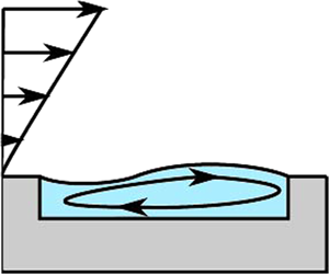

1. Introduction
Slippery lubricant-infused surfaces have received much attention in recent years since they provide a drag reduction and flow manipulation in microfluidic devices (Wong et al. Reference Wong, Kang, Tang, Smythe, Hatton, Grinthal and Aizenberg2011; Nizkaya, Asmolov & Vinogradova Reference Nizkaya, Asmolov and Vinogradova2014; Solomon, Khalil & Varanasi Reference Solomon, Khalil and Varanasi2014; Keiser et al. Reference Keiser, Keiser, Clanet and Quere2017). The lubricant could be a gas trapped by superhydrophobic (SH) textures or another liquid, such as oil. Superhydrophobic surfaces show very large effective slip length (Ybert et al. Reference Ybert, Barentin, Cottin-Bizonne, Joseph and Bocquet2007; Vinogradova & Belyaev Reference Vinogradova and Belyaev2011), which makes them attractive for use in microfluidic applications (Vinogradova & Dubov Reference Vinogradova and Dubov2012). Liquid-infused (LI) surfaces are less slippery (Asmolov, Nizkaya & Vinogradova Reference Asmolov, Nizkaya and Vinogradova2018), but are commonly considered to be potentially more stable and robust against pressure-induced failure compared to SH surfaces, which makes them useful in various applications, including anti-biofouling (Epstein et al. Reference Epstein, Wong, Belisle, Boggs and Aizenberg2012) and ice phobicity (Kim et al. Reference Kim, Wong, Alvarenga, Kreder, Adorno-Martinez and Aizenberg2012). Implementation of LI surfaces often requires a thorough understanding of the dynamics of a lubricant within a patterned substrate that is exposed to external hydrodynamic flow. This fundamental problem also applies to a variety of similar situations, including the stability of small bubbles or droplets, trapped by slightly rough or heterogeneous surfaces (Vinogradova et al. Reference Vinogradova, Bunkin, Churaev, Kiseleva, Lobeyev and Ninham1995; Borkent et al. Reference Borkent, Dammler, Schonherr, Vansco and Lohse2007).
The influence of a curved meniscus on the slipping properties of SH texture has been extensively studied analytically (Sbragaglia & Prosperetti Reference Sbragaglia and Prosperetti2007), numerically (Teo & Khoo Reference Teo and Khoo2010) and in experiments (Karatay et al. Reference Karatay, Haase, Visser, Sun, Lohse, Tsai and Lammertink2013; Xue et al. Reference Xue, Lv, Liu, Shi, Lin and Duan2015). In all these studies, protrusion or inflection of the meniscus has been achieved by changing the hydrostatic pressure in a gas, but the flow-induced dynamic deformation of the meniscus has been neglected. Deformation of a liquid/gas interface by the flow has been studied only for strongly protruding bubbles (Hyväluoma & Harting Reference Hyväluoma and Harting2008; Gao & Feng Reference Gao and Feng2009). In particular, simulation studies (Hyväluoma & Harting Reference Hyväluoma and Harting2008) have shown that, at large capillary numbers, pinned surface bubbles are deformed by an external viscous flow, which dramatically alters the slip length of the SH texture, but no attempt has been made to address the issue of their stability. We are also unaware of any study of the dynamic deformation of an initially flat meniscus.
Existing theories describing the stability of a lubricant-infused state mostly include the configurations of static wetting drops at the SH surface. Several static criteria have been suggested (Bico, Thiele & Quere Reference Bico, Thiele and Quere2002; Cottin-Bizonne et al. Reference Cottin-Bizonne, Barentin, Charlaix, Bocquet and Barrat2004), and later extended to a more complex, metastable situations (Reyssat, Yeomans & Quere Reference Reyssat, Yeomans and Quere2007; Dubov et al. Reference Dubov, Mourran, Möller and Vinogradova2015). The body of theoretical and experimental work investigating the stability of SH and LI surfaces in external flows is rather scarce, although there exists some recent literature in the area. Wexler, Jacobi & Stone (Reference Wexler, Jacobi and Stone2015) and Liu et al. (Reference Liu, Wexler, Schönecker and Stone2016) have considered an outer shear flow aligned with the direction of extended closed grooves, where a reverse pressure gradient in a lubricant is generated. As a result, the curvature of the static meniscus is largest near the channel inlet, and the failure of deep LI grooves occurs when the dynamic contact angle becomes large, while the failure of shallow grooves takes place when the meniscus contacts the groove bottom. The collapse of partially filled deep SH and LI grooves induced by an external transverse shear has been studied numerically by Ge et al. (Reference Ge, Holmgren, Kronbichler, Brandt and Kreiss2018). These authors concluded that the meniscus deformation induced by such a flow decreases with the lubricant/outer liquid viscosity ratio and that the collapse of lubricant-infused grooves is possible only when this ratio is smaller than unity.
In this paper we present some results of a study of the possible collapse of shallow lubricant-infused grooves driven by an external transverse shear flow. Our model, which is different from configurations explored before, assumes that the meniscus is initially flat and pinned at the groove edges, and that grooves are unbounded in the longitudinal direction. To solve a two-phase problem we couple a general solution of the Stokes problem for the outer flow and a lubrication approach for the flow in a groove. Note that a similar strategy has previously been successfully employed for investigating flows over flat SH textures (Maynes et al. Reference Maynes, Jeffs, Woolford and Webb2007; Nizkaya, Asmolov & Vinogradova Reference Nizkaya, Asmolov and Vinogradova2013) and evaporating thin films (Doumenc & Guerrier Reference Doumenc and Guerrier2013). We shall see that the flow induced in a lubricant layer strongly depends on its local thickness, which is in turn controlled by a local pressure gradient, and that the stationary shape of a deformed meniscus becomes roughly antisymmetric (concave–convex). The meniscus depinning from the front groove edge occurs when the advancing contact angle for the outer liquid is reached at some critical capillary number. However, very shallow lubricant-infused textures collapse when the deformed meniscus contacts the groove bottom. One of important differences between our results and prior works, which employed different models, is that the lubricant-infused surface becomes more stable when the lubricant/liquid viscosity ratio is smaller. Therefore, contrary to common belief, for some geometries SH surfaces could be more robust than LI ones.
The paper is arranged as follows. In § 2 we describe the model of a lubricant-infused shallow groove and derive asymptotic equations for a two-phase flow problem. Section 3 contains the results of our numerical calculations. We conclude in § 4. The calculation details of the meniscus shape and of the effective slip length are given in appendix A, and we justify the use of the lubrication approximation for an inner flow in appendix B.
2. Asymptotic theory
2.1. Model
We consider a linear shear flow of an outer liquid of viscosity  $\mu ^{*}$ over a shallow rectangular groove of width
 $\delta$ and depth
 $e\ll \delta$ (see figure 1a), filled with a lubricant of viscosity
 $\mu ^{l*}$ (hereafter the asterisk denotes dimensional variables). The
 $y^{*}$-axis is aligned with the shear direction, while the
 $z^{*}$-axis is defined normal to the wall, and the dimensionless coordinates are introduced as
 $y=y^{*}/\delta$ and
 $z=z^{*}/\delta$. We assume that the groove aspect ratio is small,
 $\varepsilon =e/\delta \ll 1$, and that, at rest, the static liquid/lubricant interface is flat and located at
 $z=0$, i.e. there is no pressure difference across the meniscus that is pinned at the edges of the groove. When the meniscus is perturbed by an external flow, its slightly deformed shape sketched in figure 1(b) can be described by a function
 $\varepsilon \eta (y)$, where
 $\eta =O(1)$. It is convenient to introduce the stationary angle
 $\theta \geq {\rm \pi}/2$ defined (relative to the vertical direction) at the point where the concave or flat meniscus meets the groove edge (here, the front one). Thanks to the lubricant volume conservation, the meniscus deformation should be rather close to antisymmetric, so that the stationary angle at the opposite grove edge (here the rear one) is approximately
 ${\rm \pi} - \theta$. The observed angle
 $\theta$ cannot exceed a limiting value, known as the advancing angle, beyond which the contact line depins from the groove edge and moves. Likewise, when
 ${\rm \pi} - \theta$ decreases down to a limiting value of the receding angle, the contact line should suddenly shift laterally.
Sketches of ( $a$) an outer shear flow past a shallow lubricant-infused groove of width
 $\delta$ and depth
 $e$, and of (
 $b$) a liquid/lubricant interface
 $\varepsilon \eta (y)$ in dimensionless coordinates. The concave liquid/lubricant interface meets the front groove edge with an angle
 $\theta$ defined relative to the vertical.

If we consider a chemically homogeneous (ideal) surface, the bounds of attainable values of  $\theta$ are determined unambiguously by a liquid (Young) contact angle
 $\varTheta$ (above
 ${\rm \pi} /2$ to provide a lubricant-infused state) on a planar horizontal surface (see figure 2). Its value can, of course, always be adjusted by a suitable modification of the solid surface (Jung & Bhushan Reference Jung and Bhushan2009; Grate et al. Reference Grate, Dehoff, Warner, Pittman, Wietsma, Zhang and Oostrom2012; Dubov et al. Reference Dubov, Mourran, Möller and Vinogradova2015), but note that, on most solids,
 $\varTheta$ never exceeds
 $2 {\rm \pi}/3$ or
 $120^{\circ }$ (Yakubov, Vinogradova & Butt Reference Yakubov, Vinogradova and Butt2000; Jung & Bhushan Reference Jung and Bhushan2009; Wexler et al. Reference Wexler, Jacobi and Stone2015). Following Quere (Reference Quere2008), Herminghaus, Brinkmann & Seemann (Reference Herminghaus, Brinkmann and Seemann2008) and Dubov et al. (Reference Dubov, Nizkaya, Asmolov and Vinogradova2018) one can argue that the contact angle of the liquid at the groove edges can be anywhere between
 $\varTheta$ (receding) and
 $\varTheta + {\rm \pi}/2$ (advancing), as illustrated in figure 2 by the coloured regions that are symmetric relative to a midplane of the groove. The attainable contact angles redefined relative to
 $z$-direction are then confined between
 $\varTheta - {\rm \pi}/2$ (receding) and
 $\varTheta$ (advancing). We remark and stress, however, that the bounds of attainable angles are asymmetric relative to
 $z=0$, except the case of
 $\varTheta = 3 {\rm \pi}/4$ (or
 $135^{\circ }$). Of the two possible unstable angles, one is normally attained faster and overshadows the other. Since for our surfaces
 $\varTheta$ is smaller than
 $3 {\rm \pi}/4$, one can argue that the depinning will occur on that edge of the groove, where the meniscus is concave, and where
 $\theta$ will reach the value of
 $\varTheta$. For the meniscus shape sketched in figures 1 and 2 this would be the front (left) edge, but of course such a shape is by no means obvious, and will be justified below by solving a hydrodynamic problem. As a side note we mention that the depinning would occur simultaneously at the front and rear (right) edges if
 $\varTheta = 3 {\rm \pi}/4$, and for larger
 $\varTheta$ – on a rear edge, when
 $\theta \simeq \varTheta - {\rm \pi}/2$. Clearly, these estimates hold only for ideal surfaces and relatively low speed. They would become approximate when the surface is chemically heterogeneous. However, they provide us with some guidance.
Pinning of a contact line on a rectangular groove edge. The liquid meets the solid with a contact angle  $\varTheta$. Hence, the contact angle at the groove edges can take any value (if the horizontal direction is considered as the reference one) between
 $\varTheta$ and
 $\varTheta + {\rm \pi}/2$, as illustrated by coloured region confined between the dashed lines. The attainable contact angles at the edge, redefined relative to the
 $z$-direction, are then confined between
 $\varTheta - {\rm \pi}/2$ and
 $\varTheta$.

The dimensionless velocity and pressure are defined as  ${\boldsymbol {u}}=\boldsymbol {u}^{*}/(G\delta )$ and
 $p=p^{*}/(G\mu ^{*})$, where
 $G$ is an undisturbed shear rate. We stress, that near the groove the outer flow is modified due to a slippage at the liquid/lubricant interface, and that the lubricant flow, induced by a reverse pressure gradient, has zero flow rate in any cross-section (see figure 3a). The flows in a lubricant and an outer liquid are stationary and satisfy Stokes equations
 \begin{gather} \boldsymbol{\nabla }\boldsymbol{\cdot} \boldsymbol{u}=0,\quad {\rm \Delta} \boldsymbol{u}-\boldsymbol{\nabla }p= \mathbf{0}, \end{gather}
 \begin{gather}\boldsymbol{\nabla }\boldsymbol{\cdot} \boldsymbol{u}^{l}=0,\quad \mu {\rm \Delta} \boldsymbol{u}^{l} -\boldsymbol{\nabla}p^{l}=\mathbf{0}, \end{gather}
where  $\boldsymbol {u}=(0,v,w)$ and
 $\boldsymbol {u}^{l}=(0,v^{l},w^{l})$ are velocity fields in liquid and in lubricant,
 $p, p^{l}$ are corresponding pressure distributions and
 $\mu =\mu ^{l*}/\mu ^{*}$ is the lubricant/liquid viscosity ratio. Far from the lubricant-induced surface the liquid flow represents a linear shear flow,
 $\boldsymbol {u}|_{z\to \infty }=z{\boldsymbol {e}}_y$, where
 ${\boldsymbol {e}}_y$ is a unit vector along the
 $y$-axis. We apply a no-slip condition at solid boundaries, and at the liquid/lubricant interface,
 $z=\varepsilon \eta(y)$, we use the conditions of impermeability
 \begin{equation} \boldsymbol{u}\boldsymbol{\cdot} \boldsymbol{n}={\boldsymbol{u}}^{l}\boldsymbol{\cdot} {\boldsymbol{n}}=0, \end{equation}
and of continuity of tangential velocity and tangential stress,
 \begin{gather} \boldsymbol{u}\boldsymbol{\cdot} \boldsymbol{\tau}= \boldsymbol{u}^{l}\boldsymbol{\cdot} \boldsymbol{\tau}, \end{gather}
 \begin{gather}\boldsymbol{\tau} \boldsymbol{\cdot} \boldsymbol{\sigma} \boldsymbol{\cdot} \boldsymbol{n}=\boldsymbol{\tau} \boldsymbol{\cdot} \boldsymbol{\sigma}^{l}\boldsymbol{\cdot} \boldsymbol{n}, \end{gather}
where  ${\boldsymbol {\tau }}$ and
 ${\boldsymbol {n}}$ are the unit tangent and outward normal (to the meniscus) vectors, and the stress tensors are
 $\boldsymbol {\sigma } = \boldsymbol {\nabla } \boldsymbol {u}+( \boldsymbol {\nabla } \boldsymbol {u})^\textrm {T} {-}p{\boldsymbol{\mathsf{I}}}$ and
 ${\boldsymbol {\sigma }}^{l} =\mu ({\boldsymbol {\nabla } \boldsymbol {u}}^{l}+ ({\boldsymbol {\nabla } \boldsymbol {u}}^{l})^\textrm {T}){-}p^{l} {\boldsymbol{\mathsf{I}}}$, where I is the unit tensor.
( $a$) Recirculation flow in a shallow groove. (
 $b$) Shear flow and a local slip length in outer fluid.

The condition for normal stresses at the interface can be derived using the Laplace equation,
 \begin{equation} \boldsymbol{n}\boldsymbol{\cdot} (\boldsymbol{\sigma}^{\boldsymbol{l}}-\boldsymbol{\sigma})\boldsymbol{\cdot} \boldsymbol{n}=\frac{\kappa}{{Ca}}, \end{equation}
where  $Ca=\mu ^{\ast }G\delta /\gamma$ is the capillary number defined using an outer liquid viscosity and surface tension of the interface γ, and
 $\kappa \simeq \varepsilon \eta ''$ is the interface curvature (negative for the meniscus protruding into the outer liquid).
These equations should be supplemented by the condition of volume conservation in the lubricant phase and by the pinning conditions at the edges of the groove,
 \begin{equation} \int\limits_{0}^{1}\eta(y)\,\textrm{d}y=0, \quad \eta(0)=\eta(1)=0. \end{equation}
Equations (2.1)–(2.7a,b) represent a closed system governing liquid and lubricant flows. They involve three dimensionless parameters, i.e. the shallow groove aspect ratio  $\varepsilon$, the lubricant/liquid viscosity ratio
 $\mu$ and the capillary number
 $Ca$. The two latter parameters could be any positive value, but
 $\varepsilon$ is small, so that we could use it to construct asymptotic solutions for the meniscus shape, velocity fields and pressure.
Since  $\varepsilon$ is small,
 ${\boldsymbol {\tau } }\simeq ( 0,1,\varepsilon \partial _{y}\eta )$ and
 ${\boldsymbol {n}}\simeq ( 0,-\varepsilon \partial _{y}\eta ,1)$ and the boundary conditions (2.3)–(2.5) at a curved interface can be simplified to
 \begin{equation} w=w^{l}=0, \quad v=v^{l}=v_{\eta}(y), \quad\dfrac{\partial v}{\partial z}=\mu\dfrac{\partial v^{l}}{\partial z}, \end{equation}
which defines the coupling between the liquid and the lubricant. Here,  $v_{\eta }(y)$ is the tangential velocity of both the liquid and the lubricant at the interface. From (2.6) we then obtain
 \begin{equation} \sigma^{l}_{zz}=\sigma_{zz}+\dfrac{\varepsilon\eta''}{{{Ca}}},\end{equation}
which determines the meniscus shape, with normal stresses given by
 \begin{equation} \sigma_{zz}=2 \partial _{z}w-p,\quad \sigma^{l}_{zz}=2\mu \partial _{z}w^{l}-p^{l}. \end{equation}
Note that the normal stresses include not only the pressure but also the gradients of the normal velocities since, unlike the no-slip case, the latter do not vanish at slippery surfaces.
2.2. Inner flow
The lubricant flow in the groove is generated by the interface velocity  $v_{\eta }(y)$. For this inner problem the boundary condition, (2.8a–c), should be imposed at the curved meniscus
 $z=\eta (y)$, since its local deviation from the flat one,
 $z=0$, is comparable to the depth of the groove,
 $\varepsilon$. Since the local slopes of the meniscus are small, we apply the lubrication theory and consider a locally parabolic velocity profile of zero flow rate
 \begin{equation} v^{l}\simeq v_{\eta }( y) \zeta\left(3\zeta-2\right) ,\quad w^{l}\simeq 0, \end{equation}
where  $\zeta =(z+\varepsilon )/[\varepsilon (1+\eta )]$ varies from
 $0$ at the bottom wall to
 $1$ at the interface. Equations (2.11a,b), which are equivalent to those derived by Nizkaya et al. (Reference Nizkaya, Asmolov and Vinogradova2013) for a flat meniscus, but varying local thickness of the thin lubricant film, allow one to immediately calculate both the lubricant shear rate at the interface
 \begin{equation} \partial_z v^{l}=\dfrac{4 v_{\eta}}{\varepsilon(1+\eta)}, \end{equation}
and the transverse local slip length
 \begin{equation} b(y)=\frac{v_{\eta}}{\mu \partial_z v^{l}} \simeq \frac{\varepsilon}{4 \mu}(1+\eta), \end{equation}
where  $\varepsilon /\mu =O(1)$. Equation (2.13) implies that
 $b(y)$ is proportional to a local thickness of the lubricant layer and inversely proportional to
 $\mu$, similarly to infinite systems (Miksis & Davis Reference Miksis and Davis1994; Vinogradova Reference Vinogradova1995). We should also note that
 ${\varepsilon }/{4\mu }$ may be interpreted as a local transverse slip length,
 $b_0$, on a flat (undisturbed) liquid/lubricant interface (Nizkaya et al. Reference Nizkaya, Asmolov and Vinogradova2013, Reference Nizkaya, Asmolov and Vinogradova2014).
For SH grooves, pressure induced by flow changes in the inner gas is usually neglected since  $\mu \ll 1$. However,
 $\mu$ takes on finite values for lubricant-infused surfaces, and the gradient of pressure in closed shallow grooves could become very large, even when the lubricant viscosity is small,
 $\mu \sim \varepsilon$. Using simple scaling arguments one can show that
 $\partial _{y}p^{l} \simeq \mu ({\partial ^{2}v^{l}}/{\partial y^{2}})\sim \mu \varepsilon ^{-2}\gg 1$. Indeed, the corresponding to (2.11a,b) pressure profile satisfies
 \begin{equation} \partial _{y}p^{l}\simeq \dfrac{6\mu v_{\eta }( y) }{ \varepsilon^{2}\left( 1+\eta \right) ^{2}},\quad \partial _{z}p^{l}\simeq 0. \end{equation}
Finally, using (2.14a,b) and (2.2) one can estimate that  $2\mu \partial _z w^{l} \simeq -2\mu \partial _y v^{l}\sim \mu \ll |p^{l}|$. From (2.10a,b) it then follows that
 $\sigma ^{l}_{zz} \simeq -p^{l}$, which may be determined by integrating (2.14a,b).
2.3. Outer flow
We now turn to the outer liquid flow (of length scale  $\delta$), that practically cannot be affected by small variations in
 $\varepsilon \eta$, and, therefore, (2.8a–c) can be mapped to the flat interface,
 $\boldsymbol {u}\vert _{z=\varepsilon \eta }= \boldsymbol {u}\vert _{z=0}+O(\varepsilon ).$ Impermeability condition (2.3) is then reduced to
 $w(y,0)=0,$ and (2.5) takes the form of a conventional partial slip condition applied at
 $z=0$,
 \begin{equation} v = b(y)\dfrac{\partial v}{\partial z}, \end{equation}
with the local slip length described by (2.13).
An outer solution for a flow field with prescribed velocity  $v_{\eta }( y)$ and zero normal velocity can be found using
 $u(y,z)$ for a longitudinal configuration (Asmolov & Vinogradova Reference Asmolov and Vinogradova2012)
 \begin{gather} v=u+z\frac{\partial u}{\partial z},\quad w=-z\frac{\partial u}{\partial y}, \end{gather}
 \begin{gather}p=-2\frac{\partial u}{\partial y}. \end{gather}
Here,  $u$ satisfies the Laplace equation,
 ${\rm \Delta} u=0$, with the boundary condition
 $u( 0,y) =v_{\eta }( y)$. Equations (2.16a,b), (2.17) immediately suggest that
 $\sigma _{zz}( 0,y)=2 \partial _{z}w-p=0$. In other words, the contributions of the pressure and the gradient of normal velocity to the normal stress cancel out. This implies that the outer flow does not affect the meniscus deformation. Consequently, the meniscus shape depends on the sign of the pressure gradient in the lubricant. When it is positive, the shape will be as shown in figures 1 and 2, i.e. concave at the front groove edge and convex at the rear one.
The equation describing the meniscus shape can be obtained by differentiating (2.9) with respect to  $y$. Keeping then only the leading term in
 $\varepsilon$ and using (2.11a,b) we find that this shape obeys
 \begin{equation} \eta'''=-\frac{6 \mu {{Ca}}}{\varepsilon^{3}}\dfrac{v_{\eta}(y)}{(1+\eta)^{2}}. \end{equation}
To solve this differential equation, conditions (2.7a,b) should be imposed.
To summarize, the outer asymptotic problem is reduced to (2.1) coupled with the equation for the meniscus shape (2.18) expressed via the local slip length  $b(y)$, (2.13), and interface velocity,
 $v_{\eta }$.
2.4. Limiting cases
In the general case, the inner and outer flows are strongly coupled, and the two-phase problem should be solved numerically. However, in some limits the system can be simplified, thanks to a decoupling of these flows.
In the limit of  $\varepsilon /\mu \ll 1$, typical for a very viscous lubricant and/or an extremely thin lubricant layer, (2.15) reduces to a no-slip boundary condition,
 $v(y,0)\simeq 0$. Consequently, an outer flow remains undisturbed by the inner one, and the shear stress in the liquid is
 $\partial _{z}v(y,0) \simeq 1$. It follows then from (2.8a–c) that the lubricant shear rate is
 $\partial _{z}v^{l}(y,0) \simeq \mu ^{-1}$, and the interface velocity, found from (2.15), is
 $v_{\eta }=b(y)\partial _{z}v(y,0)\simeq \varepsilon (1+\eta )/4 \mu$, i.e. it decreases with
 $\mu$. From (2.14a,b) it follows then that
 $\partial _{y}p^{l}$ is finite and does not depend on
 $\mu$, and (2.18) reduces to
 \begin{equation} \eta''' =-\dfrac{3 {{Ca}} }{2 \varepsilon^{2} \left( 1+\eta \right) }. \end{equation}
In the opposite limiting case of low lubricant viscosity,  $\varepsilon /\mu \gg 1$, the local slip length
 $b(y)$ is large provided
 $1+\eta (y)$ remains finite. Thus, we might argue that, at any deformation, a sensible approximation for a local slip would be
 $b(y) \rightarrow \infty$ that leads to the interface velocity
 $v_{\eta }^{P}( y)=[1-(2y-1)^{2}]^{1/2}/{4}$ (Philip Reference Philip1972). Substituting this to (2.18) we get
 \begin{equation} \eta'''=-\frac{6 \mu {{Ca}}}{\varepsilon^{3}}\dfrac{v_{\eta}^{p}(y)}{(1+\eta)^{2}} . \end{equation}
3. Results of calculations and discussion
In this section we present some numerical results for the model system formulated above. The details of our calculations are presented in appendix A. In appendix B we present some numerical results justifying the use of the lubrication approximation.
We have first investigated the dynamic meniscus stationary shape,  $\eta (y)$, at fixed
 $\varepsilon =0.1$. Figure 4(a) shows the numerical results obtained using
 ${{Ca}}=0.3$, and several typical viscosity contrasts,
 $\mu =0.02$ (water/air interface),
 $\mu =0.2$ (oil/water) and
 $\mu =1$, where the liquid and lubricant are of the same viscosity. Our calculations confirm that the function
 $\eta (y)$ is nearly antisymmetric and has two extrema. It takes its minimum value close to the front edge of the groove (region of concave curvature), and a maximum occurs in the vicinity of the rear edge, where
 $\eta (y)$ inverts its curvature to convex. As predicted and discussed above, this implies that the depinning occurs at the front edge. The absolute values of the extrema decrease with
 $\varepsilon /\mu$, which implies that, with our parameters, the meniscus deformation grows with
 $\mu$. Also included are predictions of the asymptotic equation (2.19), which determines an upper bound on meniscus deformation, attainable for very small
 $\varepsilon /\mu$. For smaller values of
 ${{Ca}}$, the maximum possible meniscus deformation decreases, as illustrated in figure 4(b). We also note that a larger deflection of the meniscus shape from the flat one is always accompanied by an increase in
 $\theta = {\rm \pi}/2-\arctan (\varepsilon \eta '(0))$.
( $a$) Meniscus shape computed at
 $\varepsilon =0.1$ and
 ${{Ca}}=0.3$. Solid, dashed and dash-dotted curves show results obtained using
 $\mu = 0.02$,
 $0.2$ and
 $1$. Bold curve shows calculations from the asymptotic equation (2.19). (
 $b$) Predictions of (2.19) for
 $\varepsilon =0.1$ and
 ${{Ca}}=0.1$,
 $0.2$,
 $0.3$ (dash-dotted, dashed and solid curves).

As described in § 2, the local curvature of the meniscus is associated with pressure in the lubricant film, which in turn can be related to the lubricant flow. Figure 5 plots the lubricant pressure, local slip length  $b(y)$ and the interface velocity
 $v_{\eta }(y)$ computed with the same parameters as in figure 4(a). We see that
 $p^{l}$ increases with
 $y$, and its (positive) gradient is smaller for larger
 $\varepsilon /\mu$, which implies that, at fixed
 $\varepsilon$, the pressure gradient grows with
 $\mu$. By contrast, both
 $b(y)$ and
 $v_{\eta }(y)$ increase with
 $\varepsilon /\mu$. The numerical data also show that at large
 $\varepsilon /\mu$ the interface velocity remains close to
 $v_{\eta }^{P}(y)$, but for smaller slip lengths it is significantly affected by the deformation of a lubricant film.
(a) Lubricant pressure, (b) local slip length and (c) interface velocity calculated using  $\varepsilon =0.1$ and
 ${{Ca}}=0.3$. Solid, dashed and dash-dotted curves show results for
 $\mu = 0.02$,
 $0.2$ and
 $1$. Dotted lines show results for a flat meniscus.

To examine the scenario of collapse more closely, the critical  ${{Ca}}$ has been calculated as a function of
 $\varepsilon$ for several values of
 $\mu$ (taken the same as in figures 4 and 5). Specimen results obtained using
 $\varTheta = 120^{\circ }$ and
 $110^{\circ }$ that are close to those observed experimentally (Jung & Bhushan Reference Jung and Bhushan2009; Grate et al. Reference Grate, Dehoff, Warner, Pittman, Wietsma, Zhang and Oostrom2012; Dubov et al. Reference Dubov, Mourran, Möller and Vinogradova2015; Wexler et al. Reference Wexler, Jacobi and Stone2015) are included in figures 6(a) and 6(b), where we denote by filled symbols in the
 $({{Ca}}, \varepsilon )$ plane the values of
 ${{Ca}}$, which correspond to
 $\theta = \varTheta$. It is well seen that for smaller
 $\varTheta$ the depinning should occur at smaller
 ${{Ca}}$. Note that these results agree well with calculations made using the exact equation for the meniscus curvature (shown by open symbols), confirming the validity of our approximations. As
 $\mu$ increases the value of
 ${{Ca}}$ required for a depinning reduces, and for sufficiently large
 $\mu$ should approach the value calculated from (2.19). The curve for the critical
 ${{Ca}}$ of depinning as a function of
 $\mu$, calculated using
 $\varepsilon =0.1$, is included in figure 6(c). It can be seen that it reduces rapidly at small viscosity contrast and saturates to a constant value given by (2.19) already at
 $\mu \geq 1$. We emphasize that at smaller
 $\varepsilon$ our nonlinear system has no positive stationary solution when
 ${{Ca}}$ becomes larger than some critical value. As
 ${{Ca}}$ approaches this value, the local thickness of a lubricant film tends to zero, accompanied by an infinite growth of the pressure gradient in the film neck (see appendix A), but note that
 $\theta$ still remains smaller than
 $\varTheta$. Therefore, one might argue that for sufficiently small
 $\varepsilon$ the curve of failure of lubricant-infused surfaces included in figures 6(a) and 6(b) reflects the contact of a deformed meniscus with the bottom wall that occurs before the value of
 $\varTheta$ is reached. It is interesting that the curves corresponding to these two scenarios of collapse of lubricant-infused surfaces meet smoothly at
 $\varepsilon \simeq 0.07$ (
 $\varTheta = 120^{\circ }$) and
 $\varepsilon \simeq 0.05$ (
 $\varTheta = 110^{\circ }$) in figures 6(a) and 6(b).
( $a$) Critical values of
 ${{Ca}}$, beyond which the lubricant-infused surfaces collapse, versus
 $\varepsilon$ calculated using
 $\varTheta =120^{\circ }$ and
 $\mu =0.02$ (squares),
 $0.2$ (circles),
 $1$ (diamonds). Filled and open symbols are obtained from (2.18) and (B 2), and correspond to the depinning. Dashed curves correspond to a contact of the liquid/lubricant interface with the bottom wall. (
 $b$) The same, but for
 $\varTheta =110^{\circ }$. (
 $c$) Critical
 ${{Ca}}$ at which the depinning occurs as a function of
 $\mu$ calculated for
 $\varepsilon =0.1$. Solid curves from top to bottom show results obtained using
 $\varTheta =120^{\circ }$ and
 $110^{\circ }$. Dashed lines plot the corresponding asymptotic values calculated from (2.19).

Finally, we recall that  $b_0$ is proportional to
 $\varepsilon / \mu$, so that, based on (2.18), one can suggest that the critical
 ${{Ca}} /\varepsilon ^{2}$ is a universal scaled capillary number that allows one to evaluate when the meniscus contacts the bottom and this scenario of failure of lubricant-infused surfaces occurs. To illustrate this we plot in figure 7(a) the curve separating liquid-infused and collapsed states of the lubricant-infused surfaces in the
 $({{Ca}} /\varepsilon ^{2}, \varepsilon / \mu )$ plane. The stable configuration corresponds to the area under the curve, while in the upper region the lubricant-infused surface is never stable. At
 $\varepsilon / \mu \to 0$ we recover a solution of (2.19). The critical
 ${{Ca}} /\varepsilon ^{2}$ increases with
 $\varepsilon / \mu$, and at sufficiently large
 $\varepsilon / \mu$ it grows practically linearly with the slope
 $O(10)$. This is better seen in figure 7(b), where we reproduce our data in the
 $(\mu {{Ca}} /\varepsilon ^{3}, \varepsilon / \mu )$ plane. When
 $\varepsilon / \mu \to \infty$, the solution of (2.20) becomes exact, but we might argue that it becomes a sensible approximation when
 $\varepsilon / \mu$ becomes large, i.e. for SH surfaces.
( $a$) Critical
 ${{Ca}} /\varepsilon ^{2}$ (solid curve), corresponding to a contact of the meniscus with the bottom wall, as a function of
 $\varepsilon / \mu$. The solution of (2.19) is shown by a filled circle. (
 $b$) Critical
 $\mu {{Ca}} /\varepsilon ^{3}$ (solid curve) and predictions of (2.20) that determines the asymptotic slope of critical
 ${{Ca}} /\varepsilon ^{2}$ at large
 $\varepsilon /\mu$ (dashed line).

4. Conclusion
We have studied the meniscus deformation in an outer shear flow oriented transverse to lubricant-infused shallow grooves. It has been shown that the deviations of meniscus shape from the initial one are mostly controlled by the inner, pressure-driven, lubricant flow. While such a deformation practically does not affect the value of the slip length, it could induce the collapse of the lubricant-infused surface. Whether or not such a collapse occurs depends on the capillary number  ${{Ca}}$, lubricant/liquid viscosity ratio
 $\mu$ and the aspect ratio of the groove
 $\varepsilon$. Our work has shown that, unlike the previously considered case of deep grooves, for shallow grooves the meniscus deformation increases with
 $\mu$. The mechanism of the failure of lubricant-infused shallow grooves depends, in turn, on the value of
 $\varepsilon$. We have identified two separate mechanisms of failure of lubricant-infused state of surfaces. This could happen due to a depinning of the meniscus from the front groove edge, when the value of the advancing contact angle is reached. However, in the case of very small
 $\varepsilon$, the meniscus contacts the bottom wall before such a depinning occurs.
We have already mentioned the prior numerical work of Ge et al. (Reference Ge, Holmgren, Kronbichler, Brandt and Kreiss2018) who studied deep transverse grooves, filled by a lubricant only partly (implying the mobility of the contact line), and found that the meniscus deformation decreases with  $\mu$. One important difference of our results for shallow transverse grooves with pinned contact lines is that the deformation decreases upon reducing
 $\mu$, likewise in the case of deep longitudinal grooves (Wexler et al. Reference Wexler, Jacobi and Stone2015; Liu et al. Reference Liu, Wexler, Schönecker and Stone2016). We are unaware of any reported measurements of failure of transverse LI grooved surfaces. It would be very timely to test theoretical predictions for transverse LI grooves by experiments.
Finally, we recall that, here, an ideal, chemically homogeneous surface has been assumed. For such a surface, the advancing liquid contact angle (relative to the vertical) is exactly equal to (Young) angle  $\varTheta$. For a chemically heterogeneous material the advancing angle will, of course, exceed the value of
 $\varTheta$, making the LI surface more stable against depinning. Conversely, a hypothetical surface of very large
 $\varTheta$, where depinning would be expected at the rear groove edge, becomes more stable when chemically heterogeneous since the receding angle (relative to the horizontal) is smaller than
 $\varTheta$.
Acknowledgements
This research was partly supported by the Russian Foundation for Basic Research (grant 18-01-00729) and the Ministry of Science and Higher Education of the Russian Federation.
Declaration of interests
The authors report no conflict of interest.
Appendix A. Numerical method
The asymptotic equations (2.19) and (2.20) are solved using Runge–Kutta procedure and the Newton method to satisfy boundary conditions (2.7a,b). In the general case  $\varepsilon /\mu =O(1)$, (2.1), (2.15) and (2.18) are coupled and we use an iteration scheme, starting from some initial guess. Once the meniscus shape on the
 $k$th iteration is known, we solve the Stokes equations in liquid (2.1) with the local slip length
 $b^{k}(y)=b_0[1+\eta ^{k}(y)]$. We calculate the outer flow for periodic grooves (Nizkaya et al. Reference Nizkaya, Asmolov and Vinogradova2013) and expand the solution into Fourier series on a computational domain with a period
 $L=5\delta$ (where the solution is no longer dependent on
 $L$). The local slip boundary conditions are satisfied using a collocation method. The computed interface velocity
 $v_{\eta }^{k}(y)$ is then substituted into the right-hand side of (2.18) to obtain the next iteration
 \begin{equation} \dfrac{\partial^{3}\eta^{k+1}}{\partial y^{3}}=\frac{6 \mu {{Ca}}}{\varepsilon^{3}}\dfrac{v_{\eta}^{k}(y)}{(1+\eta^{k})^{2}}. \end{equation}
The meniscus shape is also sought in terms of Fourier series,
 \begin{equation} \eta(y)=A+ B(1-y) y+ \sum_{n=1}^{N_f}\left[a_n\cos(k_ny)+b_n\sin(k_ny)\right], \end{equation}
where  $k_n=2{\rm \pi} n$ and
 $A,B, a_n, b_n$ are a set of
 $2N_f+2$ unknown coefficients. To obtain the coefficients
 $a_n, b_n$ we substitute (A 2) into (2.18) and solve the resulting system of linear equations using the collocation method. Constants
 $A$ and
 $B$ are then found from the conditions (2.7a,b):
 $A=-\sum a_n$,
 $B=-6(A+1)$.
If  $\varepsilon$ is very small, the solution becomes singular when
 ${{Ca}}$ approaches some critical value, which is also quite small. Namely, the smallest local thickness of a lubricant film tends to zero, and simultaneously the pressure gradient diverges. This is illustrated in figure 8. We see that the smallest thickness of the lubricant film slightly decreases with a small increase in
 ${{Ca}}/\varepsilon ^{2}$, but the third derivative of
 $\eta (y)$, which reflects the growth of pressure gradient in the lubricant neck, changes significantly. Beyond some critical
 ${{Ca}}$, the solution of positive film thickness does not exist, and our numerical scheme fails to converge.
( $a$) Meniscus shape, (
 $b$) its first and (
 $c$) third derivatives calculated using
 $\varepsilon /\mu \ll 1$ and
 ${{Ca}}/\varepsilon ^{2} =41.3$, 42.3, 43.3 (dotted, dashed and solid lines).

Appendix B. Validation of the model based on a lubrication approximation
In our asymptotic model we describe the flow inside the groove using the lubrication theory. It is of considerable interest to determine its accuracy and the range of validity for our configuration.
To validate this approach, here, we first present some exact results for a two-phase system with a flat meniscus. Our numerical calculations are based on the method developed by Ng, Chu & Wang (Reference Ng, Chu and Wang2010) and Nizkaya et al. (Reference Nizkaya, Asmolov and Vinogradova2014). Figure 9 shows the vector field  $(v^{l}(y,z),w^{l}(y,z))$ computed using
 $\varepsilon =0.1$ and
 $\mu =0.2$. We see that the lubricant velocity field far from the side texture wall is unidirectional, with a parabolic profile of zero mean flux, confirming all the features described by (2.11a,b). However, in the vicinity of the sidewall there is a discernible vertical velocity component, indicating that a simple lubrication model can only be considered as a first approximation.
Lubricant velocity field computed using  $\varepsilon =0.1$ and
 $\mu =0.2$.

To examine a significance of these deviations from the lubrication model more closely, in figure 10(a) we compare the exact numerical results for the velocity at the flat liquid/lubricant interface with predictions of our asymptotic model, i.e. with the solution of (2.18) obtained using  $\eta =0$. The agreement is quite good, but at
 $y \to 1$ there is some discrepancy, and the lubrication theory slightly overestimates the interface velocity. We have also calculated streamwise velocity profiles in a lubricant. Results for cross-sections
 $y = 0.75$ and
 $y = 0.95$ are plotted in figure 10(b). The exact velocity profiles fully coincide with the lubrication model when
 $y = 0.75$, but close to the side texture wall,
 $y=0.95$, we again observe some deviations of the lubrication theory data from the exact results. Nevertheless, the calculations demonstrate that this discrepancy is small.
( $a$) Velocity at the interface of a flat meniscus and (
 $b$) inner velocity profiles at cross-sections
 $y = 0.75$ and 0.95 calculated for
 $\varepsilon =0.1$ and
 $\mu =0.2$. Solid curves show the exact solutions, dashed curves plot results of the lubrication theory.

Another possible source of inaccuracy of the lubrication model is the use of the small-curvature approximation,  $\kappa \simeq \varepsilon \eta ''$, in (2.9), instead of an exact equation for the curvature,
 \begin{equation} \kappa=\dfrac{\varepsilon\eta''}{\left(1+\varepsilon^{2}\eta'^{2}\right)^{3/2}}. \end{equation}
Note that the exact equation for curvature involves higher-order terms in  $\varepsilon$, which are neglected in our model. However, sometimes this equation is successfully employed to improve the accuracy of lubrication approaches (Gauglitz & Radke Reference Gauglitz and Radke1988; Snoeijer Reference Snoeijer2006; Thiele Reference Thiele2018). Moreover, the inclusion of such terms can even lead to drastic changes in the critical behaviour of the system (von Borries Lopes, Thiele & Hazel Reference von Borries Lopes, Thiele and Hazel2018), which have not been observed in our case.
Equation (2.18) governing the meniscus shape can be rewritten using (B 1) as
 \begin{equation} \left[\frac{\eta ^{\prime \prime }}{\left( 1+\varepsilon ^{2}\eta ^{\prime 2}\right) ^{3/2}}\right]^{\prime} =-\frac{6\mu \mathrm{Ca }}{\varepsilon ^{3}}\dfrac{v_{\eta }(y)}{(1+\eta )^{2}}. \end{equation}
In § 3, we compare the numerical solutions of (2.18) and (B 2) for several  $\mu$ (see figures 6a and 6b), and show that critical behaviour persists and the depinning values of
 ${{Ca}}$ are very close. This implies that
 $\varepsilon \eta ^{\prime }$ always remains small and can safely be neglected.



