1 Introduction
Active matter has been attracting much interest from a broad range of research communities (Ramaswamy Reference Ramaswamy2010; Cates & MacKintosh Reference Cates and MacKintosh2011; Marchetti et al. Reference Marchetti, Joanny, Ramaswamy, Liverpool, Prost, Rao and Simha2013; Needleman & Dogic Reference Needleman and Dogic2017). At the micron scale, active matter consists of a large number of active agents that are able to convert energy to achieve directed or persistent motions, which include those of living microorganisms, synthetic micro-robots, biopolymers such as actin filaments, etc. The motions of these active agents are attributed to a wide range of mechanisms (Lauga & Powers Reference Lauga and Powers2009; Marchetti et al. Reference Marchetti, Joanny, Ramaswamy, Liverpool, Prost, Rao and Simha2013; Alapan et al. Reference Alapan, Yasa, Yigit, Yasa, Erkoc and Sitti2019), e.g. one of the most common strategies adopted by natural and artificial micro-swimmers lies in the beating and wiggling of slender structures such as cilia and filaments, which are hair-like slender microscale structures that play an important role in various biological processes (Fawcett Reference Fawcett, Brachet and Mirsky1961), such as swimming, pumping, mixing, cytoplasmic streaming, etc. The biological organelles deliver these functionalities by performing rhythmic, wave-like motions.
To achieve persistent motions, cyclic or oscillatory motions are needed, yet, the mechanism underlying the emergence of such oscillations remains unclear. Two major hypotheses, geometric feedback (Brokaw Reference Brokaw1971; Hines & Blum Reference Hines and Blum1983; Riedel-Kruse, Müller & Oates Reference Riedel-Kruse, Müller and Oates2007; Brokaw Reference Brokaw2009; Hilfinger, Chattopadhyay & Jülicher Reference Hilfinger, Chattopadhyay and Jülicher2009; Sartori et al. Reference Sartori, Geyer, Scholich, Jülicher and Howard2016) and ‘flutter’ or buckling instability (Bayly & Dutcher Reference Bayly and Dutcher2016; De Canio, Lauga & Goldstein Reference De Canio, Lauga and Goldstein2017; Fatehiboroujeni, Gopinath & Goyal Reference Fatehiboroujeni, Gopinath and Goyal2018; Hu & Bayly Reference Hu and Bayly2018; Ling, Guo & Kanso Reference Ling, Guo and Kanso2018), have been raised based on theory and/or simulations: the first hypothesis assumes that a time-dependent dynein activity (switching on/off or modulation) is necessary to trigger the oscillations; the second one suggests that a steady point force or force distributions acting along the axial direction of a flexible filament can trigger its oscillatory motion through a ‘flutter’ or buckling instability. These forces are in fact called the ‘follower force’ in the mechanics literature (Pflüger Reference Pflüger1950; Ziegler Reference Ziegler1952; Herrmann & Bungay Reference Herrmann and Bungay1964). Because the follower force was initially invented theoretically and assumed to be always tangential to the slender structure regardless of its time-dependent deformation, it was demonstrated only mathematically and has been considered impractical (Koiter Reference Koiter1996). However, it was recently realised experimentally on a metre-scale rod (Bigoni et al. Reference Bigoni, Kirillov, Misseroni, Noselli and Tommasini2018).
To drive the oscillations of artificial cilia and filaments of micron scale, different methods that exploit magnetic (Dreyfus et al. Reference Dreyfus, Baudry, Roper, Fermigier, Stone and Bibette2005; Singh, Laibinis & Hatton Reference Singh, Laibinis and Hatton2005; Evans et al. Reference Evans, Shields, Carroll, Washburn, Falvo and Superfine2007; Livanovičs & Cēbers Reference Livanovičs and Cēbers2012; Hanasoge et al. Reference Hanasoge, Ballard, Hesketh and Alexeev2017; Huang et al. Reference Huang, Uslu, Katsamba, Lauga, Sakar and Nelson2019), electrostatic (den Toonder et al. Reference den Toonder, Bos, Broer, Filippini, Gillies, de Goede, Mol, Reijme, Talen, Wilderbeek, Khatavkar and Anderson2008), piezoelectric (Kieseok et al. Reference Kieseok, Chung, Devasia and Riley2009), optical (van Oosten, Bastiaansen & Broer Reference van Oosten, Bastiaansen and Broer2009) and hydrogel-based actuations (Sidorenko et al. Reference Sidorenko, Krupenkin, Taylor, Fratzl and Aizenberg2007; Masuda et al. Reference Masuda, Hidaka, Murase, Akimoto, Nagase, Okano and Yoshida2013) have been developed. Nonetheless, these practises relied on a time-dependent power source, except for the self-oscillation of polymer brushes triggered by the Belousov–Zhabotinsky reaction (Masuda et al. Reference Masuda, Hidaka, Murase, Akimoto, Nagase, Okano and Yoshida2013). This reaction-based beating shares with other biological processes, such as mammalian otoacoustic emissions (Gold Reference Gold1948; Kemp Reference Kemp1979) and glycolysis (Sel’kov Reference Sel’kov1968) the same feature: self-oscillation, that is generating and sustaining a periodic motion based on a power source without a corresponding periodicity (Jenkins Reference Jenkins2013).
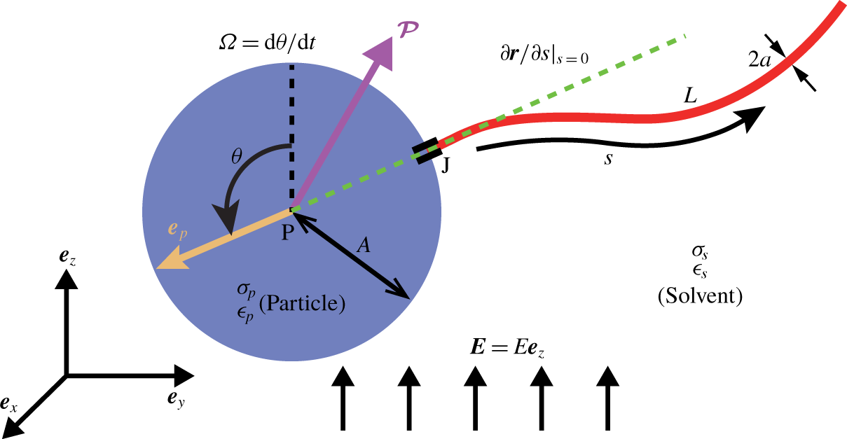
Schematic of the set-up: a dielectric spherical particle of radius  $A$ attached with a flexible filament of contour length
 $L$ is exposed to a steady uniform electrical field
 $\boldsymbol{E}=E\boldsymbol{e}_{z}$. The composite object’s motion, orientation
 $\boldsymbol{e}_{p}$ and induced dipole
 $\boldsymbol{{\mathcal{P}}}$ are all constrained to the
 $yz$-plane, and
 $\boldsymbol{e}_{p}$ is described by the angle
 $\unicode[STIX]{x1D703}$ with respect to
 $\boldsymbol{e}_{z}$.

In our recent work (Zhu & Stone Reference Zhu and Stone2019), we proposed a chemical-reaction-free and follower-force-free strategy to engineer the self-oscillations of artificial structures by employing a time-independent, uniform electric field. We reported an elasto-electro-hydrodynamic (EEH) instability based on the Quincke rotation (QR) instability, and utilised it to drive various motions of an object composed of a dielectric spherical particle with an attached elastic filament. In this work, we will present in detail the set-up and the mathematical description of the new EEH problem. First, we numerically solve the system coupling the electrohydrodynamics of the particle in a dielectric fluid and the elastohydrodynamics of the filament in a viscous fluid. We identify the emergence of the EEH instability that produces the self-oscillation of the composite object. The oscillations in turn cause the object to translate. Then, we perform a linear stability analysis (LSA) incorporating an elastohydrodynamic model to predict the onset of self-oscillatory instability. Finally, we propose a minimal model that can reproduce the similar EEH instability.
We describe the set-up and governing equations of the EEH problem in § 2, and demonstrate the numerical results in § 3. The elastohydrodynamic model and LSA are shown in § 4, followed by § 5 illustrating the minimal model. Finally, we conclude our observations and provide some discussions in § 6.
2 Problem set-up and mathematical formulations
We consider a weakly conducting dielectric spherical particle of radius  $A$, which has attached an inextensible elastic filament of contour length
 $L$. The filament is cylindrical with a constant cross-section of radius
 $a$, and its slenderness is
 $\unicode[STIX]{x1D716}_{sl}=a/L\ll 1$. We fix
 $\unicode[STIX]{x1D716}_{sl}=0.01$ in this work. The composite object is subject to a time-independent uniform electric field
 $\boldsymbol{E}=E\boldsymbol{e}_{z}$ (see figure 1), where
 $\boldsymbol{e}_{z}$ is the
 $z$-direction basis vector of the laboratory coordinates system
 $\boldsymbol{e}_{xyz}$. The centreline of the filament is described by
 $\boldsymbol{r}(s,t)$, where
 $s$ indicates the arclength. The base J (
 $s=0$) of the filament is clamped at the particle surface, namely, the tangent vector
 $\unicode[STIX]{x2202}\boldsymbol{r}/\unicode[STIX]{x2202}s|_{s=0}=-\boldsymbol{e}_{p}$ at the base always passes through the particle centre P, regardless of its deformation and the orientation vector
 $\boldsymbol{e}_{p}$ of the particle. The size ratio between the particle and filament is
 $\unicode[STIX]{x1D6FC}=A/L$. We consider only the bending deformation of the filament with a bending stiffness of
 $D=\unicode[STIX]{x03C0}a^{4}Y/4$, where
 $Y$ denotes Young’s modulus.
The composite object is immersed in a dielectric solvent fluid with dynamic viscosity  $\unicode[STIX]{x1D707}$. The electrical conductivity and absolute permittivity of the solvent are
 $\unicode[STIX]{x1D70E}_{s}$ and
 $\unicode[STIX]{x1D716}_{s}$, respectively, and those of the particle are
 $\unicode[STIX]{x1D70E}_{p}$ and
 $\unicode[STIX]{x1D716}_{p}$;
 $R=\unicode[STIX]{x1D70E}_{p}/\unicode[STIX]{x1D70E}_{s}$ and
 $S=\unicode[STIX]{x1D716}_{p}/\unicode[STIX]{x1D716}_{s}$ indicate the ratios. The ratios
 $\unicode[STIX]{x1D70F}_{s}=\unicode[STIX]{x1D716}_{s}/\unicode[STIX]{x1D70E}_{s}$ and
 $\unicode[STIX]{x1D70F}_{p}=\unicode[STIX]{x1D716}_{p}/\unicode[STIX]{x1D70E}_{p}$ denote the charge relaxation time of the solvent and particle, respectively. These electrical properties are important to the induced QR electrohydrodynamic instability that is critical to the dynamics in this paper. Their values are based on experiments (Brosseau, Hickey & Vlahovska Reference Brosseau, Hickey and Vlahovska2017), where
 $R=2.3\times 10^{-7}$ and
 $S=0.84$ are fixed in this work. Although the filament will also be polarised like the particle, the induced electric torque on the filament will be much weaker than that on the particle (see § 6 for a detailed discussion). We thus do not consider the electrohydrodynamics of the filament in this work.
2.1 Assumptions
The numerical simulations are carried out by invoking several assumptions. Motivated by biomimetic applications at the micron scale, we neglect the inertia of the fluid and particle. The fluid motion is therefore governed by the Stokes equations, and the particle satisfies instantaneous force- and torque-free conditions. The movement of the composite object is constrained to be planar, such that the particle centre P and filament position  $\boldsymbol{r}(s,t)$ are in the
 $yz$-plane.
We adopt the local resistive-force theory (Batchelor Reference Batchelor1970) to calculate the hydrodynamic forces on the filament. We further ignore the hydrodynamic interactions between the particle and the filament. In the elastohydrodynamic model developed for LSA, we also assume that the filament undergoes weak deformation.
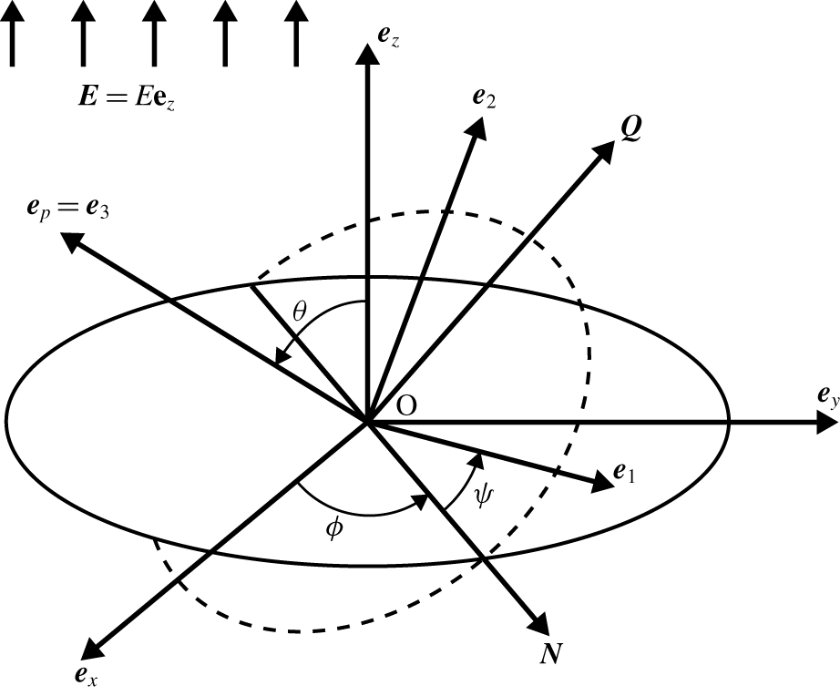
The reference frame  $\boldsymbol{e}_{123}$ that rotates and translates with the particle, the orientation
 $\boldsymbol{e}_{p}$ of the composite object coincides with
 $\boldsymbol{e}_{3}$. The proper Euler angles
 $[\unicode[STIX]{x1D703},\unicode[STIX]{x1D719},\unicode[STIX]{x1D713}]$ are adopted to describe the orientation
 $\boldsymbol{e}_{p}$, where
 $\boldsymbol{N}$ denotes the nodal line direction and
 $\boldsymbol{Q}=\boldsymbol{e}_{3}\times \boldsymbol{N}$. We note that a graphical error occurred in a similar figure in our related work (Zhu & Stone Reference Zhu and Stone2019), where
 $\unicode[STIX]{x1D713}$ ranges from
 $\boldsymbol{N}$ but erroneously to
 $\boldsymbol{e}_{y}$.

2.2 Electrohydrodynamics of the particle
When a dielectric particle in a dielectric solvent is exposed to an electric field, the interface of the particle will be polarised. The total induced dipole  $\boldsymbol{{\mathcal{P}}}^{total}$ consists of an instantaneous part
 $\boldsymbol{{\mathcal{P}}}^{\infty }$ and a retarding part
 $\boldsymbol{{\mathcal{P}}}$, viz.
 $\boldsymbol{{\mathcal{P}}}^{total}=\boldsymbol{{\mathcal{P}}}^{\infty }+\boldsymbol{{\mathcal{P}}}$. Both vectors are defined by three components,
 ${\mathcal{P}}_{i}^{\infty }$ and
 ${\mathcal{P}}_{i}$ (
 $i=1...3$) in the reference frame
 $\boldsymbol{e}_{123}$ that rotates with the particle (see figure 2). For a homogeneous spherical particle, its Maxwell–Wagner polarisation time,
 $\unicode[STIX]{x1D70F}_{MW}$, and low- and high-frequency susceptibilities,
 $\unicode[STIX]{x1D712}^{0}$ and
 $\unicode[STIX]{x1D712}^{\infty }$, respectively, are isotropic, hence the
 $i$th component of the instantaneous dipole
 $\boldsymbol{{\mathcal{P}}}^{\infty }$ is
 $$\begin{eqnarray}{\mathcal{P}}_{i}^{\infty }=\unicode[STIX]{x1D712}^{\infty }E_{i}.\end{eqnarray}$$
In the rotating reference frame of the particle, the retarding dipole  $\boldsymbol{{\mathcal{P}}}$ is governed by (Tsebers Reference Tsebers1980; Cēbers, Lemaire & Lobry Reference Cēbers, Lemaire and Lobry2000)
 $$\begin{eqnarray}\frac{\unicode[STIX]{x2202}{\mathcal{P}}_{i}}{\unicode[STIX]{x2202}t}=-\frac{1}{\unicode[STIX]{x1D70F}_{MW}}[{\mathcal{P}}_{i}-(\unicode[STIX]{x1D712}^{0}-\unicode[STIX]{x1D712}^{\infty })E_{i}],\end{eqnarray}$$
where
 $$\begin{eqnarray}\unicode[STIX]{x1D705}=\frac{R+2}{S+2},\end{eqnarray}$$
and  $\unicode[STIX]{x1D70F}_{MW}=\unicode[STIX]{x1D70F}_{s}/\unicode[STIX]{x1D705}$. It is well known that when the charge relaxation time
 $\unicode[STIX]{x1D70F}_{p}$ of the particle is larger than that of the solvent
 $\unicode[STIX]{x1D70F}_{s}$, i.e.
 $R/S<1$,
 $\boldsymbol{{\mathcal{P}}}$ is oriented opposite to the electric field. This directional misalignment is the necessary condition for the electro-rotation of the particle, the so-called Quincke rotation (Quincke Reference Quincke1896), which occurs when, in addition, the strength
 $E$ of the electric field is above a critical value
 $E^{cri}$ derived theoretically as (Jones Reference Jones1984; Brosseau et al. Reference Brosseau, Hickey and Vlahovska2017) (see appendix B)
 $$\begin{eqnarray}E^{cri}=\sqrt{\frac{2\unicode[STIX]{x1D70E}_{s}\unicode[STIX]{x1D707}(R+2)^{2}}{3\unicode[STIX]{x1D716}_{s}^{2}(S-R)}}.\end{eqnarray}$$
We do not consider the hydrodynamic interactions between the spherical particle and filament, hence the dynamics of the particle can be obtained by using its translational and rotational mobility factors. Assuming that the particle rotates at angular velocity  $\unicode[STIX]{x1D734}$ about its centre P, which translates at velocity
 $\boldsymbol{U}$, the force and torque balances on the particle give
 $$\begin{eqnarray}\displaystyle & \displaystyle \boldsymbol{F}^{f\rightarrow p}-\unicode[STIX]{x1D6FD}_{drag}\boldsymbol{U}=\mathbf{0}, & \displaystyle\end{eqnarray}$$
 $$\begin{eqnarray}\displaystyle & \displaystyle \unicode[STIX]{x1D71E}^{f\rightarrow p}+\unicode[STIX]{x1D71E}^{elec}-\unicode[STIX]{x1D6FE}_{drag}\unicode[STIX]{x1D734}=\mathbf{0}, & \displaystyle\end{eqnarray}$$
 $\boldsymbol{F}^{f\rightarrow p}$ denotes the force exerted by the filament on the particle,
 $\unicode[STIX]{x1D71E}^{f\rightarrow p}$ the torque with respect to the particle centre P and
 $\unicode[STIX]{x1D6FD}_{drag}=6\unicode[STIX]{x03C0}\unicode[STIX]{x1D707}A$ and
 $\unicode[STIX]{x1D6FE}_{drag}=8\unicode[STIX]{x03C0}\unicode[STIX]{x1D707}A^{3}$ are the translational and rotational drag coefficients of a sphere in the creeping flow, respectively. Also,
 $\unicode[STIX]{x1D71E}^{elec}$ is the electric torque on the particle with respect to its centre P, that is
 $$\begin{eqnarray}\unicode[STIX]{x1D71E}^{elec}=\boldsymbol{{\mathcal{P}}}^{total}\times \boldsymbol{E}=\boldsymbol{{\mathcal{P}}}^{\infty }\times \boldsymbol{E}+\boldsymbol{{\mathcal{P}}}\times \boldsymbol{E}=\boldsymbol{{\mathcal{P}}}\times \boldsymbol{E},\end{eqnarray}$$
where  $\boldsymbol{{\mathcal{P}}}^{\infty }\times \boldsymbol{E}\equiv \mathbf{0}$ for an isotropic sphere because
 ${\mathcal{P}}_{i}^{\infty }$ linearly scales with
 $E_{i}$ in each direction by the same factor
 $\unicode[STIX]{x1D712}^{\infty }$ (see (2.1)). It is worth noting that
 $\boldsymbol{{\mathcal{P}}}^{\infty }\times \boldsymbol{E}\neq \mathbf{0}$ for ellipsoidal particles, where the factor
 $\unicode[STIX]{x1D712}^{\infty }$ is direction dependent (Cēbers et al. Reference Cēbers, Lemaire and Lobry2000; Brosseau et al. Reference Brosseau, Hickey and Vlahovska2017). The translation of the particle is driven by the elastic force exerted by the filament, which is balanced by the viscous drag, while the rotational motion of the particle is determined by the balance between the elastic, electric and hydrodynamic torques.
The orientation of the particle  $\boldsymbol{e}_{p}$ is defined as the direction from the filament base J towards the particle centre P, where
 $\boldsymbol{e}_{3}$ of the particle-based reference frame coincides with
 $\boldsymbol{e}_{p}$. We have found it convenient to use the proper Euler angles
 $[\unicode[STIX]{x1D703},\unicode[STIX]{x1D719},\unicode[STIX]{x1D713}]$, see figure 2. Here,
 $\boldsymbol{{\mathcal{P}}}$ is decomposed into
 $\boldsymbol{{\mathcal{P}}}={\mathcal{P}}_{3}\boldsymbol{e}_{3}+{\mathcal{P}}_{N}\boldsymbol{N}+{\mathcal{P}}_{Q}\boldsymbol{Q}$, where
 $\boldsymbol{N}$ indicates the nodal line direction and
 $\boldsymbol{Q}=\boldsymbol{e}_{3}\times \boldsymbol{N}$. This decomposition applies to other vectorial variables such as
 $\boldsymbol{E}$. We constrain
 $\boldsymbol{{\mathcal{P}}}$ onto the
 $yz$-plane, hence
 $\unicode[STIX]{x1D719}=\unicode[STIX]{x1D713}\equiv 0$ and
 $\unicode[STIX]{x1D703}$ is the only angle indicating the orientation
 $\boldsymbol{e}_{p}$; additionally,
 ${\mathcal{P}}_{N}=0$ and
 $\boldsymbol{e}_{x}=\boldsymbol{N}$. For the sake of completeness, we first derive the governing equations for a general situation without these constraints.
Using the torque-free condition (2.5b), we obtain the governing equations for  $[\unicode[STIX]{x1D703},\unicode[STIX]{x1D719},\unicode[STIX]{x1D713}]$,
 $$\begin{eqnarray}\displaystyle & \displaystyle \frac{\unicode[STIX]{x2202}\unicode[STIX]{x1D703}}{\unicode[STIX]{x2202}t}=\frac{1}{\unicode[STIX]{x1D6FE}_{d}}(\unicode[STIX]{x1D6E4}_{N}^{f\rightarrow p}+E_{3}{\mathcal{P}}_{Q}-E_{Q}{\mathcal{P}}_{3}), & \displaystyle\end{eqnarray}$$
 $$\begin{eqnarray}\displaystyle & \displaystyle {\displaystyle \frac{\unicode[STIX]{x2202}\unicode[STIX]{x1D719}}{\unicode[STIX]{x2202}t}}={\displaystyle \frac{1}{\unicode[STIX]{x1D6FE}_{drag}}}\sin \unicode[STIX]{x1D703}(-E_{3}{\mathcal{P}}_{N}+\unicode[STIX]{x1D6E4}_{Q}^{f\rightarrow p}), & \displaystyle\end{eqnarray}$$
 $$\begin{eqnarray}\displaystyle & \displaystyle {\displaystyle \frac{\unicode[STIX]{x2202}\unicode[STIX]{x1D713}}{\unicode[STIX]{x2202}t}}={\displaystyle \frac{1}{\unicode[STIX]{x1D6FE}_{drag}}}\sin \unicode[STIX]{x1D703}(E{\mathcal{P}}_{N}-\unicode[STIX]{x1D6E4}_{Q}^{f\rightarrow p}\cos \unicode[STIX]{x1D703}), & \displaystyle\end{eqnarray}$$
 $E_{3}=E\cos \unicode[STIX]{x1D703}$ and
 $E_{Q}=E\sin \unicode[STIX]{x1D703}$. The governing equations for
 $[{\mathcal{P}}_{N},{\mathcal{P}}_{Q},{\mathcal{P}}_{3}]$ are (Cēbers et al. Reference Cēbers, Lemaire and Lobry2000)
 $$\begin{eqnarray}\displaystyle & \displaystyle \frac{\unicode[STIX]{x2202}{\mathcal{P}}_{N}}{\unicode[STIX]{x2202}t}+\frac{\unicode[STIX]{x2202}\unicode[STIX]{x1D713}}{\unicode[STIX]{x2202}t}{\mathcal{P}}_{Q}=-\frac{1}{\unicode[STIX]{x1D70F}_{MW}}{\mathcal{P}}_{N}, & \displaystyle\end{eqnarray}$$
 $$\begin{eqnarray}\displaystyle & \displaystyle \frac{\unicode[STIX]{x2202}{\mathcal{P}}_{Q}}{\unicode[STIX]{x2202}t}-\frac{\unicode[STIX]{x2202}\unicode[STIX]{x1D713}}{\unicode[STIX]{x2202}t}{\mathcal{P}}_{N}=-\frac{1}{\unicode[STIX]{x1D70F}_{MW}}[{\mathcal{P}}_{Q}-(\unicode[STIX]{x1D712}^{0}-\unicode[STIX]{x1D712}^{\infty })E_{Q}], & \displaystyle\end{eqnarray}$$
 $$\begin{eqnarray}\displaystyle & \displaystyle \frac{\unicode[STIX]{x2202}{\mathcal{P}}_{3}}{\unicode[STIX]{x2202}t}=-\frac{1}{\unicode[STIX]{x1D70F}_{MW}}[{\mathcal{P}}_{3}-(\unicode[STIX]{x1D712}^{0}-\unicode[STIX]{x1D712}^{\infty })E_{3}]. & \displaystyle\end{eqnarray}$$
We choose the charge relaxation time of the solvent  $\unicode[STIX]{x1D70F}_{s}$ as the characteristic time,
 $L/\unicode[STIX]{x1D70F}_{s}$ the characteristic velocity and
 $E^{cri}$ and
 $D/(LE^{cri})$ the characteristic strength of the electrical field and polarisation dipole, respectively. Using
 $\bar{\text{}}$ to indicate the dimensionless variables hereafter, the dimensionless equations for the Euler angles
 $[\unicode[STIX]{x1D703},\unicode[STIX]{x1D719},\unicode[STIX]{x1D713}]$ are
 $$\begin{eqnarray}\displaystyle & \displaystyle \frac{\unicode[STIX]{x2202}\unicode[STIX]{x1D703}}{\unicode[STIX]{x2202}\bar{t}}=\frac{1}{\bar{\unicode[STIX]{x1D702}}}(\bar{\unicode[STIX]{x1D6E4}}_{N}^{f\rightarrow p}+\bar{E}_{3}\bar{{\mathcal{P}}}_{Q}-\bar{E}_{Q}\bar{{\mathcal{P}}}_{3}), & \displaystyle\end{eqnarray}$$
 $$\begin{eqnarray}\displaystyle & \displaystyle {\displaystyle \frac{\unicode[STIX]{x2202}\unicode[STIX]{x1D719}}{\unicode[STIX]{x2202}\bar{t}}}=\frac{1}{\bar{\unicode[STIX]{x1D702}}\sin \unicode[STIX]{x1D703}}(-\bar{E}_{3}\bar{{\mathcal{P}}}_{N}+\bar{\unicode[STIX]{x1D6E4}}_{Q}^{f\rightarrow p}), & \displaystyle\end{eqnarray}$$
 $$\begin{eqnarray}\displaystyle & \displaystyle \frac{\unicode[STIX]{x2202}\unicode[STIX]{x1D713}}{\unicode[STIX]{x2202}\bar{t}}=\frac{1}{\bar{\unicode[STIX]{x1D702}}\sin \unicode[STIX]{x1D703}}(\bar{E}\bar{{\mathcal{P}}}_{N}-\bar{\unicode[STIX]{x1D6E4}}_{Q}^{f\rightarrow p}\cos \unicode[STIX]{x1D703}), & \displaystyle\end{eqnarray}$$
 $\bar{\unicode[STIX]{x1D71E}}^{f\rightarrow p}$. Here,
 $$\begin{eqnarray}\bar{\unicode[STIX]{x1D702}}=\unicode[STIX]{x1D6FC}^{3}\bar{\unicode[STIX]{x1D707}},\end{eqnarray}$$
with
 $$\begin{eqnarray}\bar{\unicode[STIX]{x1D707}}=\frac{8\unicode[STIX]{x03C0}\unicode[STIX]{x1D707}L^{4}}{D\unicode[STIX]{x1D70F}_{s}},\end{eqnarray}$$
defined as the elasto-electro-viscous (EEV) parameter. The dimensionless governing equations for  $[\bar{{\mathcal{P}}}_{N},\bar{{\mathcal{P}}}_{Q},\bar{{\mathcal{P}}}_{3}]$ following from (2.8) are
 $$\begin{eqnarray}\displaystyle & \displaystyle \frac{\unicode[STIX]{x2202}\bar{{\mathcal{P}}}_{N}}{\unicode[STIX]{x2202}\bar{t}}=-\unicode[STIX]{x1D705}\bar{{\mathcal{P}}}_{N}-\frac{\unicode[STIX]{x2202}\unicode[STIX]{x1D713}}{\unicode[STIX]{x2202}\bar{t}}\bar{{\mathcal{P}}}_{Q}, & \displaystyle\end{eqnarray}$$
 $$\begin{eqnarray}\displaystyle & \displaystyle \frac{\unicode[STIX]{x2202}\bar{{\mathcal{P}}}_{Q}}{\unicode[STIX]{x2202}\bar{t}}=-\unicode[STIX]{x1D705}(\bar{{\mathcal{P}}}_{Q}+\unicode[STIX]{x1D705}\bar{\unicode[STIX]{x1D702}}\bar{E}_{Q})+\frac{\unicode[STIX]{x2202}\unicode[STIX]{x1D713}}{\unicode[STIX]{x2202}t}\bar{{\mathcal{P}}}_{N}, & \displaystyle\end{eqnarray}$$
 $$\begin{eqnarray}\displaystyle & \displaystyle \frac{\unicode[STIX]{x2202}\bar{{\mathcal{P}}}_{3}}{\unicode[STIX]{x2202}\bar{t}}=-\unicode[STIX]{x1D705}(\bar{{\mathcal{P}}}_{3}+\unicode[STIX]{x1D705}\bar{\unicode[STIX]{x1D702}}\bar{E}_{3}), & \displaystyle\end{eqnarray}$$
 $\unicode[STIX]{x1D705}=(R+2)/(S+2)$ as defined in (2.3). We slightly perturb the instantaneous polarisation
 $\bar{\boldsymbol{{\mathcal{P}}}}^{\infty }$ and use it as the initial value
 $\bar{\boldsymbol{{\mathcal{P}}}}_{ini}$ of
 $\bar{\boldsymbol{{\mathcal{P}}}}$, where
 $$\begin{eqnarray}\displaystyle & \displaystyle \bar{\boldsymbol{{\mathcal{P}}}}^{\infty }=\frac{\bar{\unicode[STIX]{x1D702}}\unicode[STIX]{x1D705}^{2}\bar{E}}{\unicode[STIX]{x1D705}-(R-1)/(S-1)}(\boldsymbol{e}_{Q}\sin \unicode[STIX]{x1D703}+\boldsymbol{e}_{3}\cos \unicode[STIX]{x1D703}), & \displaystyle\end{eqnarray}$$
 $$\begin{eqnarray}\displaystyle & \displaystyle \bar{\boldsymbol{{\mathcal{P}}}}_{ini}=\bar{\boldsymbol{{\mathcal{P}}}}^{\infty }+\unicode[STIX]{x1D716}_{{\mathcal{P}}}|\bar{\boldsymbol{{\mathcal{P}}}}^{\infty }|, & \displaystyle\end{eqnarray}$$
 $\unicode[STIX]{x1D716}_{{\mathcal{P}}}=O(10^{-4})-O(10^{-3})$.
The dimensionless force- and torque-free conditions are
 $$\begin{eqnarray}\displaystyle & \displaystyle \bar{\boldsymbol{F}}^{\,f\rightarrow p}-3\unicode[STIX]{x1D6FC}\bar{\unicode[STIX]{x1D707}}\bar{\boldsymbol{U}}/4=\mathbf{0}, & \displaystyle\end{eqnarray}$$
 $$\begin{eqnarray}\displaystyle & \displaystyle \bar{\unicode[STIX]{x1D71E}}^{f\rightarrow p}+\bar{\boldsymbol{{\mathcal{P}}}}\times \bar{\boldsymbol{E}}-\bar{\unicode[STIX]{x1D702}}\bar{\unicode[STIX]{x1D734}}=\mathbf{0}. & \displaystyle\end{eqnarray}$$
Since we constrain the motion of the composite object and the induced dipole  $\bar{\boldsymbol{{\mathcal{P}}}}$ to the
 $yz$-plane, we solve (2.9a), (2.12b) and (2.12c) for
 $\unicode[STIX]{x1D703}$,
 $\bar{{\mathcal{P}}}_{Q}$ and
 $\bar{{\mathcal{P}}}_{3}$, where the last term
 $(\unicode[STIX]{x2202}\unicode[STIX]{x1D713}/\unicode[STIX]{x2202}t)\bar{{\mathcal{P}}}_{N}$ in (2.12b) vanishes.
2.3 Elastohydrodynamics of the filament
We describe here the elastohydrodynamic equations for the filament. By employing the slender body theory (SBT) considering the leading-order local drag (Batchelor Reference Batchelor1970), the relation between the velocity  $\boldsymbol{r}_{t}$ of the filament centreline and the force per unit length exerted by the fluid onto the filament
 $\boldsymbol{f}(s,t)$ is
 $$\begin{eqnarray}8\unicode[STIX]{x03C0}\unicode[STIX]{x1D707}(\boldsymbol{r}_{t}-\boldsymbol{U}^{\infty })=c(\boldsymbol{I}+\boldsymbol{r}_{s}\boldsymbol{r}_{s})\boldsymbol{\cdot }\boldsymbol{f},\end{eqnarray}$$
where  $\boldsymbol{U}^{\infty }$ is the underlying flow velocity (background or imposed flow velocity) at
 $\boldsymbol{r}(s,t)$ and
 $\boldsymbol{U}^{\infty }=\mathbf{0}$ in this work; the subscripts
 $t$ and
 $s$ denote the partial derivatives with respect to
 $t$ and
 $s$, respectively and
 $$\begin{eqnarray}c=1+2\log \unicode[STIX]{x1D716}_{sl}<0.\end{eqnarray}$$
The filament is assumed to be described by the Euler–Bernoulli constitutive law, and because the elastic force balances the hydrodynamic force anywhere on the centreline, we obtain
 $$\begin{eqnarray}\boldsymbol{f}(s)=-(T(s)\boldsymbol{r}_{s})_{s}+D\boldsymbol{r}_{ssss},\end{eqnarray}$$
where  $T(s,t)$ denotes the line tension, which acts as a Lagrangian multiplier to guarantee the inextensibility of the filament, i.e.
 $\boldsymbol{r}_{s}\boldsymbol{\cdot }\boldsymbol{r}_{s}\equiv 1$.
By substituting (2.17) into (2.15), and choosing  $L$ and
 $D/L^{2}$ as the characteristic length and force, respectively, we obtain the dimensionless equations for
 $\bar{\boldsymbol{r}}(\bar{s},\bar{t})$,
 $$\begin{eqnarray}\bar{\unicode[STIX]{x1D707}}\bar{\boldsymbol{r}}_{\bar{t}}=-2c\bar{T}_{\bar{s}}\bar{\boldsymbol{r}}_{\bar{s}}-c\bar{T}\bar{\boldsymbol{r}}_{\bar{s}\bar{s}}+c\bar{\boldsymbol{r}}_{\bar{s}\bar{s}\bar{s}\bar{s}}+c(\bar{\boldsymbol{r}}_{\bar{s}}\boldsymbol{\cdot }\bar{\boldsymbol{r}}_{\bar{s}\bar{s}\bar{s}\bar{s}})\bar{\boldsymbol{r}}_{\bar{s}}.\end{eqnarray}$$
The dimensionless equation for  $\bar{T}(\bar{s})$ reads,
 $$\begin{eqnarray}2c\bar{T}_{\bar{s}\bar{s}}-c\bar{T}\bar{\boldsymbol{r}}_{\bar{s}\bar{s}}\boldsymbol{\cdot }\bar{\boldsymbol{r}}_{\bar{s}\bar{s}}=-7c\bar{\boldsymbol{r}}_{\bar{s}\bar{s}}\boldsymbol{\cdot }\bar{\boldsymbol{r}}_{\bar{s}\bar{s}\bar{s}\bar{s}}-6c\bar{\boldsymbol{r}}_{\bar{s}\bar{s}\bar{s}}\boldsymbol{\cdot }\bar{\boldsymbol{r}}_{\bar{s}\bar{s}\bar{s}}-\bar{\unicode[STIX]{x1D707}}\unicode[STIX]{x1D6FD}_{p}(1-\bar{\boldsymbol{r}}_{\bar{s}}\boldsymbol{\cdot }\bar{\boldsymbol{r}}_{\bar{s}}),\end{eqnarray}$$
where the last term on the right-hand side  $-\bar{\unicode[STIX]{x1D707}}\unicode[STIX]{x1D6FD}_{p}(1-\bar{\boldsymbol{r}}_{\bar{s}}\cdot \bar{\boldsymbol{r}}_{\bar{s}})$ is an extra (numerical) penalisation term introduced (Tornberg & Shelley Reference Tornberg and Shelley2004; Li et al. Reference Li, Manikantan, Saintillan and Spagnolie2013) to preserve the local inextensibility constraint
 $\bar{\boldsymbol{r}}_{\bar{s}}\boldsymbol{\cdot }\bar{\boldsymbol{r}}_{\bar{s}}\equiv 1$;
 $\unicode[STIX]{x1D6FD}_{p}=100$ is adopted in our simulations. The boundary conditions (BCs) for
 $\bar{\boldsymbol{r}}(\bar{s},\bar{t})$ and
 $\bar{T}(\bar{s},\bar{t})$ at the free end
 $\bar{s}=1$ are
 $$\begin{eqnarray}\displaystyle & \displaystyle \bar{\boldsymbol{r}}_{\bar{s}\bar{s}}=\bar{\boldsymbol{r}}_{\bar{s}\bar{s}\bar{s}}=\mathbf{0}, & \displaystyle\end{eqnarray}$$
 $$\begin{eqnarray}\displaystyle & \displaystyle \bar{T}=0. & \displaystyle\end{eqnarray}$$
 $\bar{s}=0$ couple the elastohydrodynamics and electrohydrodynamics, as will be described next.
2.4 Elasto-electro-hydrodynamic coupling
The electrohydrodynamics of the dielectric particle in a dielectric solvent and the elastohydrodynamics of the flexible filament in a viscous fluid are coupled via, first the BCs of  $\bar{\boldsymbol{r}}(\bar{s},\bar{t})$ and
 $\bar{T}(\bar{s},\bar{t})$ at the filament base
 $\bar{s}=0$, and second the elastic force
 $\bar{\boldsymbol{F}}^{\,f\rightarrow p}(\bar{t})$ and torque
 $\bar{\unicode[STIX]{x1D71E}}^{f\rightarrow p}(\bar{t})$ exerted by the filament on the particle (2.14).
The BCs at the filament base  $\bar{s}=0$ are
 $$\begin{eqnarray}\displaystyle & \displaystyle \bar{\boldsymbol{r}}=\bar{\boldsymbol{x}}_{p}+\unicode[STIX]{x1D6FC}\bar{\boldsymbol{r}}_{\bar{s}}, & \displaystyle\end{eqnarray}$$
 $$\begin{eqnarray}\displaystyle & \displaystyle \bar{\boldsymbol{r}}_{\bar{s}}=-\boldsymbol{e}_{p}, & \displaystyle\end{eqnarray}$$
 $\bar{\boldsymbol{x}}_{p}(\bar{t})$ denotes the dimensionless position of the particle centre P. Equations (2.21a) and (2.21b) imply, respectively, that the filament base
 $\bar{s}=0$ is exactly on the particle surface, and the filament tangent vector at
 $\bar{s}=0$ always passes through the particle centre. Moreover,
 $\bar{\boldsymbol{x}}_{p}(\bar{t})$ and
 $\boldsymbol{e}_{p}(\bar{t})$ are connected to the particle kinematics through
 $$\begin{eqnarray}\displaystyle & \displaystyle \frac{\text{d}\bar{\boldsymbol{x}}_{p}}{\text{d}\bar{t}}=\bar{\boldsymbol{U}}, & \displaystyle\end{eqnarray}$$
 $$\begin{eqnarray}\displaystyle & \displaystyle \frac{\text{d}\boldsymbol{e}_{p}}{\text{d}\bar{t}}=\bar{\unicode[STIX]{x1D734}}\times \boldsymbol{e}_{p}, & \displaystyle\end{eqnarray}$$
 $\bar{\boldsymbol{U}}(\bar{t})$ is linked to (2.14a) and
 $\bar{\unicode[STIX]{x1D734}}(\bar{t})$ to (2.9). The coupling is completed by the computation of
 $\bar{\boldsymbol{F}}^{\,f\rightarrow p}$ and
 $\bar{\unicode[STIX]{x1D71E}}^{f\rightarrow p}$,
 $$\begin{eqnarray}\displaystyle & \displaystyle \bar{\boldsymbol{F}}^{\,f\rightarrow p}=[-\bar{\boldsymbol{r}}_{\bar{s}\bar{s}\bar{s}}+\bar{T}\bar{\boldsymbol{r}}_{\bar{s}}]|_{\bar{s}=0}, & \displaystyle\end{eqnarray}$$
 $$\begin{eqnarray}\displaystyle & \displaystyle \bar{\unicode[STIX]{x1D71E}}^{f\rightarrow p}=[\bar{\boldsymbol{r}}_{\bar{s}}\times (\bar{\boldsymbol{r}}_{\bar{s}\bar{s}}-\unicode[STIX]{x1D6FC}\bar{\boldsymbol{r}}_{\bar{s}\bar{s}\bar{s}})]|_{\bar{s}=0}. & \displaystyle\end{eqnarray}$$
For completeness, we write the BC for the tension  $\bar{T}$ at the filament base
 $\bar{s}=0$
 $$\begin{eqnarray}2c\bar{T}_{\bar{s}}+6c\bar{\boldsymbol{r}}_{\bar{s}\bar{s}}\boldsymbol{\cdot }\bar{\boldsymbol{r}}_{\bar{s}\bar{s}\bar{s}}=-\bar{\unicode[STIX]{x1D707}}\bar{\boldsymbol{r}}_{\bar{s}}\boldsymbol{\cdot }\bar{\boldsymbol{r}}_{\bar{t}}.\end{eqnarray}$$
3 Numerical results
In the original QR phenomenon (without a filament), the particle rotates when the dimensionless electric field is above  $1$, namely,
 $\bar{E}\geqslant 1$. We hereby investigate the influence of the bending stiffness of the filament by varying
 $\bar{\unicode[STIX]{x1D707}}$, where we fix the electric field
 $\bar{E}=1.5$ at which an individual particle undergoes steady QR. We fix the size ratio
 $\unicode[STIX]{x1D6FC}=0.3$ in this section.
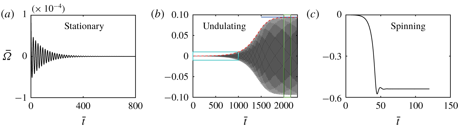
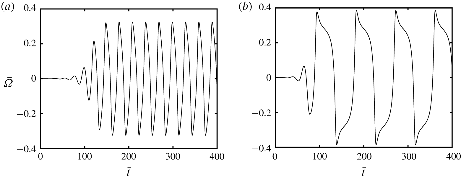
We observe that the composite object exhibits three  $\bar{\unicode[STIX]{x1D707}}$-dependent scenarios, indicated by the time evolution of the rotational velocity
 $\bar{\unicode[STIX]{x1D6FA}}$ shown in figure 3. When
 $\bar{\unicode[STIX]{x1D707}}=600$ (figure 3a),
 $\bar{\unicode[STIX]{x1D6FA}}$ decays dramatically and eventually becomes zero, indicating that the object relaxes to a stationary state. Increasing
 $\bar{\unicode[STIX]{x1D707}}$ to 635 (figure 3b), the time evolution of
 $\bar{\unicode[STIX]{x1D6FA}}$ features two phases: in the initial phase (cyan domain), it grows rapidly due to self-oscillation; in the second phase (green domain), it reaches a time-periodic state with a constant amplitude of approximately 0.1. The third type of response is illustrated by
 $\bar{\unicode[STIX]{x1D707}}=2000$, where
 $\bar{\unicode[STIX]{x1D6FA}}$ eventually approaches a steady value around - 0. 6.
The  $\bar{\unicode[STIX]{x1D707}}$-dependent time evolution of the rotational velocity
 $\bar{\unicode[STIX]{x1D6FA}}(\bar{t})$ for (a)
 $\bar{\unicode[STIX]{x1D707}}=600$, (b)
 $\bar{\unicode[STIX]{x1D707}}=635$ and (c)
 $\bar{\unicode[STIX]{x1D707}}=2000$ when
 $\bar{E}=1.5$. Their corresponding equilibrium configurations are stationary, undulating and steady spinning, respectively. Note that
 $\bar{\unicode[STIX]{x1D6FA}}_{\bar{t}=0}$ is not necessarily zero because the induced dipole
 $\bar{\boldsymbol{{\mathcal{P}}}}$ is slightly perturbed at
 $\bar{t}=0$, see (2.13); moreover, (a) and (b) have strikingly different scales for
 $\bar{\unicode[STIX]{x1D6FA}}$.

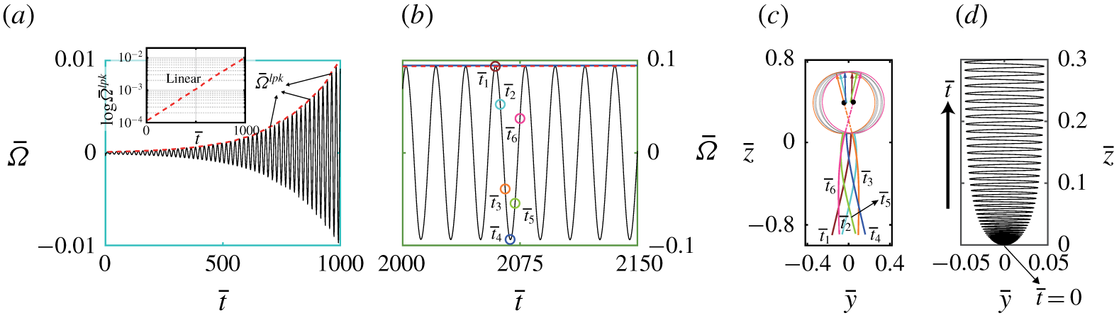
(a) Highlighted cyan domain of figure 3(b) indicating the initial rapidly growing period of  $\bar{\unicode[STIX]{x1D6FA}}(\bar{t})$, for
 $\bar{\unicode[STIX]{x1D707}}=635$ and
 $\bar{E}=1.5$. The red curve denotes the local peak
 $\bar{\unicode[STIX]{x1D6FA}}^{lpk}$, and the inset of (a) shows the linear dependence of
 $\log \bar{\unicode[STIX]{x1D6FA}}^{lpk}$ on
 $\bar{t}$. (b) Highlighted green domain of figure 3(b) corresponding to the time-periodic response of
 $\bar{\unicode[STIX]{x1D6FA}}(\bar{t})$, where consecutive time instants
 $\bar{t}_{i}$ (
 $i=1,\ldots ,6$) within a period are marked. (c) Particle–filament configurations at
 $\bar{t}_{i}$. (d) Trajectory of the particle centre within
 $\bar{t}\in [0,1940]$.

We further scrutinise the  $\bar{\unicode[STIX]{x1D707}}=635$ case. The close-up views of the initially rapidly growing phase (cyan domain) and saturated time-periodic phase (green domain) are shown in figures 4(a) and 4(b), respectively. The red curve connecting the local peaks
 $\bar{\unicode[STIX]{x1D6FA}}^{lpk}$ of
 $\bar{\unicode[STIX]{x1D6FA}}$ implies an exponential growth of
 $\bar{\unicode[STIX]{x1D6FA}}$ in time. This trend is confirmed by the linear relationship between
 $\log \bar{\unicode[STIX]{x1D6FA}}^{lpk}$ and
 $\bar{t}$ shown in the inset of figure 4(a). The time-periodic phase enlarged in figure 4(b) reveals its sinusoidal-like variation characterised by fore–aft temporal symmetry. Six times within one period of this phase are marked, with their corresponding positions and orientations of the particle, and the profiles of the filament depicted in figure 4(c). The oscillating particle drives the filament to wiggle, because the filament is clamped onto the particle. The wiggling filament provides thrust to the whole object, as a natural resemblance to a biological appendage. Consequently, the object achieves locomotion, following a wave-like trajectory (figure 4d). The wavy path is tightly packed near
 $\bar{t}=0$, implying the slow motion of the object undergoing small-amplitude oscillation in the initial phase.
Time evolution of the rotational velocity  $\bar{\unicode[STIX]{x1D6FA}}(\bar{t})$ when
 $\bar{E}=1.5$ for (a)
 $\bar{\unicode[STIX]{x1D707}}=825$ and (b)
 $\bar{\unicode[STIX]{x1D707}}=1000$.

We observe that when  $\bar{\unicode[STIX]{x1D707}}$ lies in the self-oscillating regime, the time evolution of
 $\bar{\unicode[STIX]{x1D6FA}}$ varies with
 $\bar{\unicode[STIX]{x1D707}}$. As shown in figure 5 for
 $\bar{\unicode[STIX]{x1D707}}=825$ and 1000, for a larger
 $\bar{\unicode[STIX]{x1D707}}$ it takes fewer time periods for the perturbation to reach its time-periodic state. In addition, that state clearly breaks fore–aft symmetry with increasing
 $\bar{\unicode[STIX]{x1D707}}$.
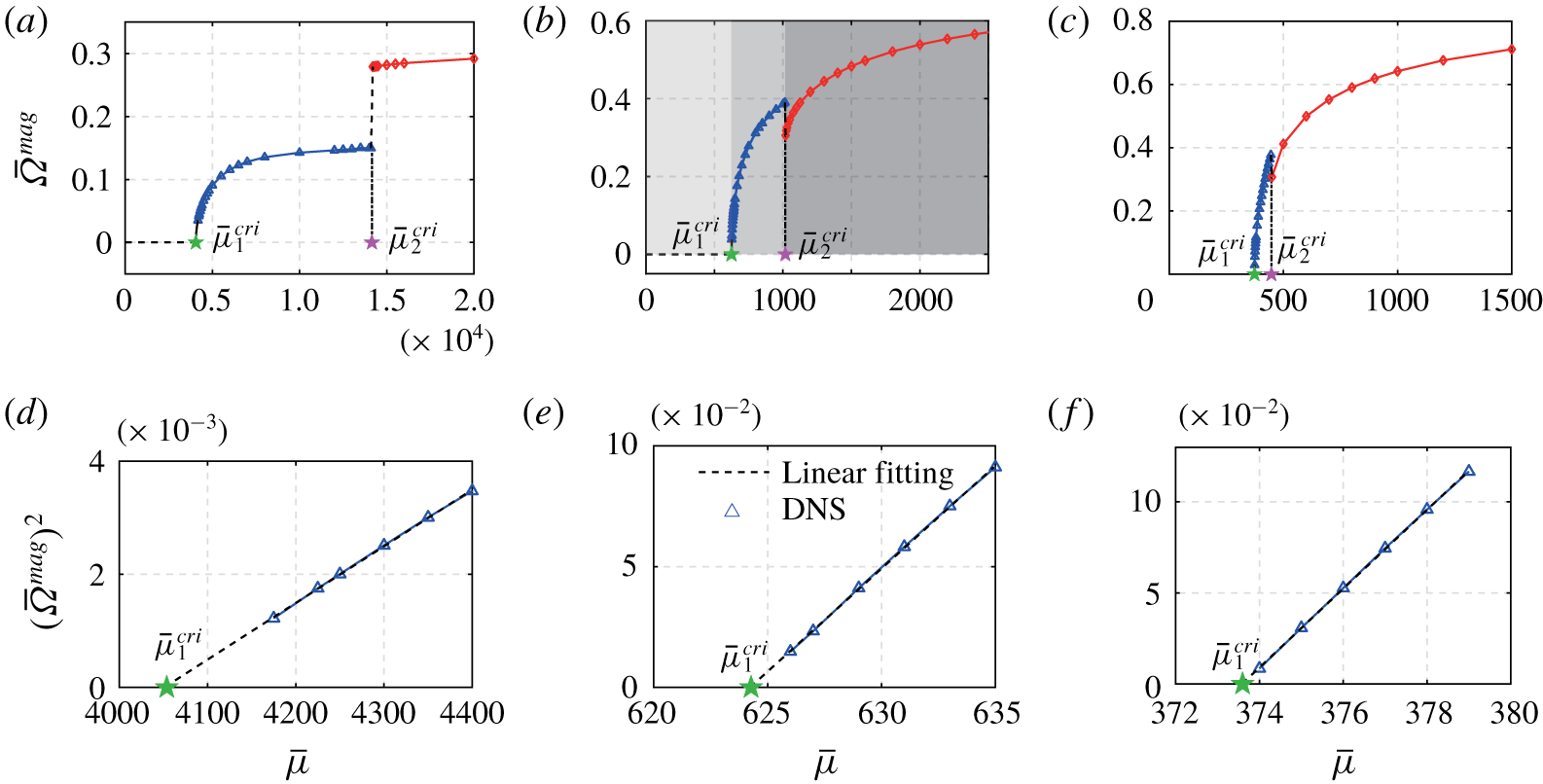
Amplitude  $\bar{\unicode[STIX]{x1D6FA}}^{mag}$ of the rotational velocity as a function
 $\bar{\unicode[STIX]{x1D707}}$ for (a)
 $\bar{E}=1.2$, (b)
 $1.5$ and (c) 1.7. The three
 $\bar{\unicode[STIX]{x1D707}}$-dependent regimes, stationary (dashed lines), undulating (triangles) and steady spinning (diamonds) of the composite object are separated by two thresholds
 $\bar{\unicode[STIX]{x1D707}}_{1}^{cri}$ and
 $\bar{\unicode[STIX]{x1D707}}_{2}^{cri}$. (d,e,f) Show the linear variation of
 $(\bar{\unicode[STIX]{x1D6FA}}^{mag})^{2}$ in
 $\bar{\unicode[STIX]{x1D707}}$ in close proximity to
 $\bar{\unicode[STIX]{x1D707}}_{1}^{cri}$ for
 $\bar{E}=1.2$, 1.5 and 1.7, respectively.

We next investigate the critical  $\bar{\unicode[STIX]{x1D707}}$ values that separate the three regimes corresponding to the stationary, undulating and steady spinning states. Figure 6 displays the rotational velocity magnitude
 $\bar{\unicode[STIX]{x1D6FA}}^{mag}$ versus
 $\bar{\unicode[STIX]{x1D707}}$ for
 $\bar{E}=1.2$ (a), 1.5 (b) and 1.7 (c). When
 $\bar{\unicode[STIX]{x1D707}}\leqslant \bar{\unicode[STIX]{x1D707}}_{1}^{cri}$,
 $\bar{\unicode[STIX]{x1D6FA}}^{mag}=0$ represents the fixed-point solution; when
 $\bar{\unicode[STIX]{x1D707}}\geqslant \bar{\unicode[STIX]{x1D707}}_{1}^{cri}$, the non-zero
 $\bar{\unicode[STIX]{x1D6FA}}^{mag}$ representing the constant spinning speed corresponds to the asymmetric fixed-point solution; when
 $\bar{\unicode[STIX]{x1D707}}\in (\bar{\unicode[STIX]{x1D707}}_{1}^{cri},\bar{\unicode[STIX]{x1D707}}_{2}^{cri})$,
 $\bar{\unicode[STIX]{x1D6FA}}^{mag}$ indicates the magnitude of the oscillating
 $\bar{\unicode[STIX]{x1D6FA}}$ when it reaches a time-periodic state. We plot
 $(\bar{\unicode[STIX]{x1D6FA}}^{mag})^{2}$ as a function of
 $\bar{\unicode[STIX]{x1D707}}$ in close proximity to
 $\bar{\unicode[STIX]{x1D707}}_{1}^{cri}$ in figure 6(d–f). The linear dependence of
 $(\bar{\unicode[STIX]{x1D6FA}}^{mag})^{2}$ on
 $\bar{\unicode[STIX]{x1D707}}$ implies that the instability occurs at
 $\bar{\unicode[STIX]{x1D707}}_{1}^{cri}$ through a Hopf bifurcation from where a limit-cycle solution emerges. Moreover, the
 $\bar{\unicode[STIX]{x1D6FA}}^{mag}(\bar{\unicode[STIX]{x1D707}})$ profile also indicates the supercritical nature of the Hopf bifurcation. On the other hand, a sudden jump of
 $\bar{\unicode[STIX]{x1D6FA}}^{mag}$ at
 $\bar{\unicode[STIX]{x1D707}}_{2}^{cri}$ signifies a secondary bifurcation where the limit cycle shrinks to a fixed point or vice versa.
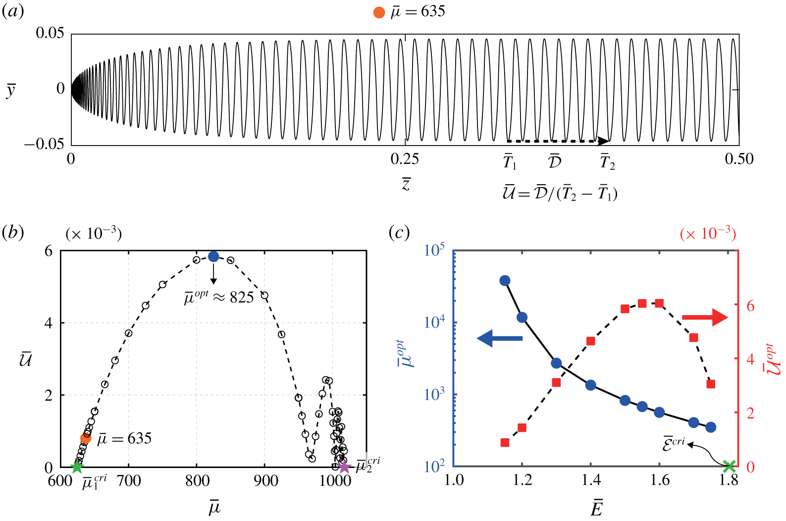
(a) Trajectory of the particle centre for  $\bar{\unicode[STIX]{x1D707}}=635$, when
 $\bar{E}=1.5$. The dashed arrow indicates how the effective translational velocity
 $\bar{{\mathcal{U}}}$ is quantified. (b)
 $\bar{{\mathcal{U}}}$ versus
 $\bar{\unicode[STIX]{x1D707}}\in (\bar{\unicode[STIX]{x1D707}}_{1}^{cri},\bar{\unicode[STIX]{x1D707}}_{2}^{cri})$ when
 $\bar{E}=1.5$,
 $\bar{{\mathcal{U}}}$ reaches an optimal value
 $\bar{{\mathcal{U}}}^{opt}\approx 6\times 10^{-3}$ at
 $\bar{\unicode[STIX]{x1D707}}=\bar{\unicode[STIX]{x1D707}}^{opt}\approx 825$. (c) The optimal EEV number
 $\bar{\unicode[STIX]{x1D707}}^{opt}$ when the composite object attains the maximum effective translational velocity
 $\bar{{\mathcal{U}}}^{opt}$;
 $\bar{\unicode[STIX]{x1D707}}^{opt}$ and
 $\bar{{\mathcal{U}}}^{opt}$ are plotted versus the field strength
 $\bar{E}$.

Having demonstrated that the composite object is able to achieve propulsion by self-oscillatory undulation, we naturally examine its propulsive performance. Shown in figure 7(a), when the undulating swimmer reaches its time-periodic state, its trajectory resembles a periodic wave propagating along a straight direction (dashed arrow). We thus define the effective translational velocity  $\bar{{\mathcal{U}}}$ of the swimmer as the propagation speed of the wave, that is
 $\bar{{\mathcal{U}}}=\bar{{\mathcal{D}}}/(\bar{T}_{2}-\bar{T}_{1})$. This effective velocity
 $\bar{{\mathcal{U}}}$ exhibits a clear non-monotonic variation in
 $\bar{\unicode[STIX]{x1D707}}$; it reaches its maximum value at an optimal EEV number
 $\bar{\unicode[STIX]{x1D707}}=\bar{\unicode[STIX]{x1D707}}^{opt}\approx 825$ and becomes zero when
 $\bar{\unicode[STIX]{x1D707}}\rightarrow \bar{\unicode[STIX]{x1D707}}_{1}^{cri}$ and
 $\bar{\unicode[STIX]{x1D707}}\rightarrow \bar{\unicode[STIX]{x1D707}}_{2}^{cri}$. Such a non-monotonic trend is expected, since when
 $\bar{\unicode[STIX]{x1D707}}$ is outside the self-oscillating regime
 $[\bar{\unicode[STIX]{x1D707}}_{1}^{cri},\bar{\unicode[STIX]{x1D707}}_{2}^{cri}]$, the object either remains stationary or spins steadily, resulting in no net locomotion. It is also worth noting that
 $\bar{{\mathcal{U}}}$ exhibits wavy variation near
 $\bar{\unicode[STIX]{x1D707}}_{2}^{cri}$. In this regime, the filament is so deflected and the hydrodynamic interactions between the particle and filament can be reasonably strong due to the decreasing distance between them. Since our simulations do not consider the hydrodynamic interactions, hence it is not self-consistent to interrogate the data in detail in this regime.
Finally, we show in figure 7(c) the dependence of the optimal swimming condition,  $\bar{\unicode[STIX]{x1D707}}^{opt}$ and
 $\bar{{\mathcal{U}}}^{opt}$, on the electric field strength
 $\bar{E}$. The optimal EEV number
 $\bar{\unicode[STIX]{x1D707}}^{opt}$ decreases with
 $\bar{E}$ monotonically; in contrast, the optimal velocity
 $\bar{{\mathcal{U}}}^{opt}$ displays a non-monotonic variation in
 $\bar{E}$, reaching a maximum value of approximately 6 × 10⁻³ at
 $\bar{E}\approx 1.55-1.6$. This non-monotonic trend is not surprising. In fact, self-oscillation of the composite object only emerges when
 $1<\bar{E}<\bar{{\mathcal{E}}}^{cri}$, where
 $\bar{{\mathcal{E}}}^{cri}$ represents the critical electric field above which the particle jointed with a rigid rod (
 $\bar{\unicode[STIX]{x1D707}}\rightarrow 0$) of the same length and slenderness will undergo the QR instability. Hence, when
 $\bar{E}\geqslant \bar{{\mathcal{E}}}^{cri}$, the composite object will spin steadily but not self-propel regardless of the filament rigidity. On the other hand, when
 $\bar{E}\leqslant 1$, the extra anchored filament will further stabilise the original QR particle, hence the composite object will be stationary. We further note that the optimal translational velocity ≈6 × 10⁻³ is in the range
 $(1,15)\times 10^{-3}$ of the dimensionless speed of a magnetically driven flexible artificial flagellum (Dreyfus et al. Reference Dreyfus, Baudry, Roper, Fermigier, Stone and Bibette2005).
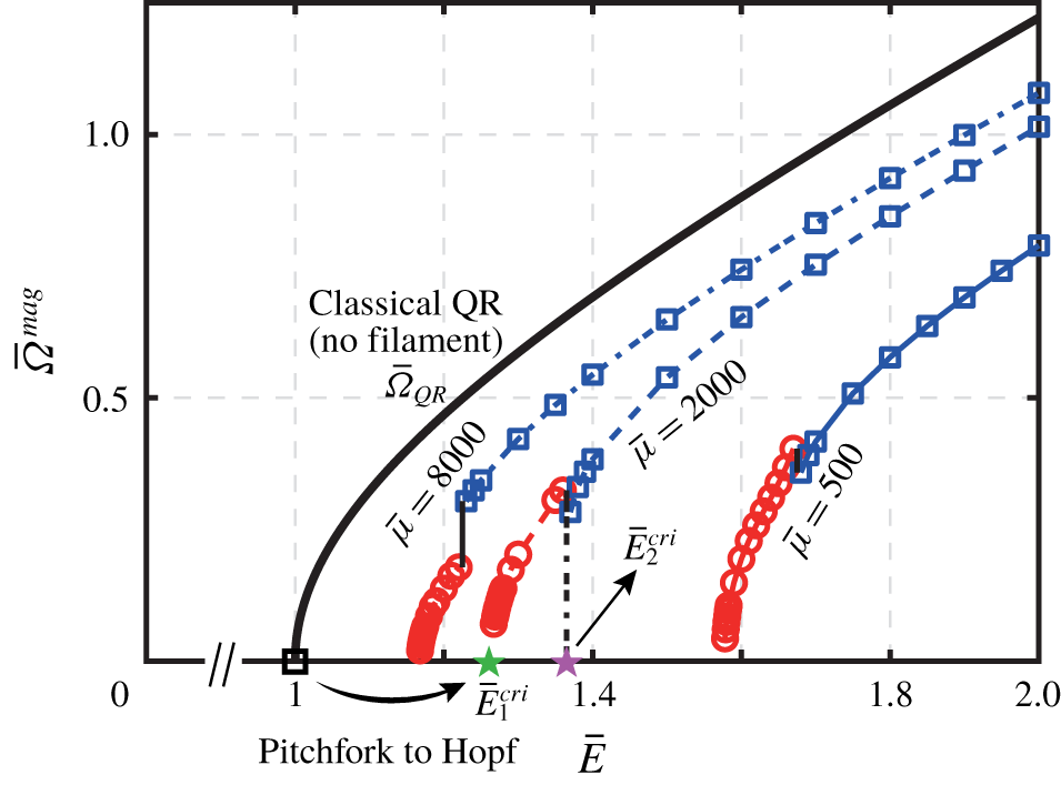
Amplitude  $\bar{\unicode[STIX]{x1D6FA}}^{mag}$ of the rotational velocity versus
 $\bar{E}$ for three EEV numbers
 $\bar{\unicode[STIX]{x1D707}}=500$, 2000 and 8000.
 $\bar{E}_{1}^{cri}$ (green star) and
 $\bar{E}_{2}^{cri}$ (magenta star) indicate where the Hopf and secondary bifurcations occur, respectively. The solid curve corresponds to the original QR rotational velocity,
 $\bar{\unicode[STIX]{x1D6FA}}_{QR}$ (see (B 5)) and the hollow square denotes
 $\bar{E}=1$, the occurrence of the pitchfork bifurcation.

By analogy to the results in figure 6(a–c), we show in figure 8  $\bar{\unicode[STIX]{x1D6FA}}^{mag}$ versus
 $\bar{E}$ as the bifurcation parameter for three EEV numbers
 $\bar{\unicode[STIX]{x1D707}}=500$, 2000 and 8000. A similar bifurcation diagram is identified: increasing
 $\bar{E}$ from zero, the stationary fixed-point solution transits to a limit-cycle solution through a supercritical Hopf bifurcation at
 $\bar{E}_{1}^{cri}$ (green star); that solution then jumps to a second fixed-point solution (steady spinning) via a secondary bifurcation at
 $\bar{E}_{2}^{cri}$ (magenta star). The original QR instability emerges at
 $\bar{E}=1$ (hollow square) through a supercritical pitchfork bifurcation (Turcu Reference Turcu1987; Peters, Lobry & Lemaire Reference Peters, Lobry and Lemaire2005; Das & Saintillan Reference Das and Saintillan2013). The filament manages to transform that bifurcation for an individual particle into a corresponding Hopf bifurcation leading to self-oscillation. It is not surprising that by increasing
 $\bar{\unicode[STIX]{x1D707}}$, the variation of
 $\bar{\unicode[STIX]{x1D6FA}}^{mag}$ for the composite object tends to recover that of the original QR corresponding to
 $\bar{\unicode[STIX]{x1D707}}\rightarrow \infty$.
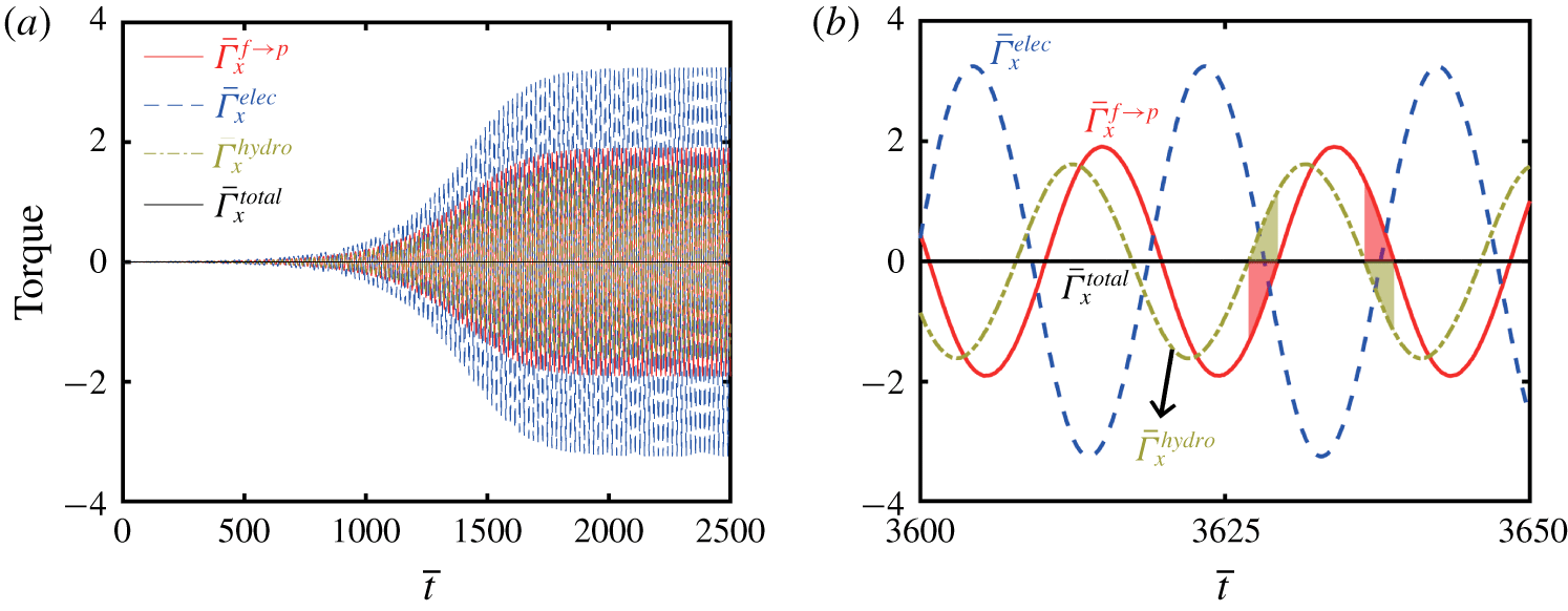
(a) Time evolution of the elastic  $\bar{\unicode[STIX]{x1D6E4}}_{x}^{f\rightarrow p}$ (solid), electric
 $\bar{\unicode[STIX]{x1D6E4}}_{x}^{elec}$ (dashed), hydrodynamic
 $\bar{\unicode[STIX]{x1D6E4}}_{x}^{hydro}$ (dot-dashed) and total
 $\bar{\unicode[STIX]{x1D6E4}}_{x}^{total}$ (straight solid) torque (
 $x$-component) on the particle with respect to its centre, where
 $\bar{\unicode[STIX]{x1D707}}=635$ and
 $\bar{E}=1.5$. (b) Close-up view of the time-periodic state. Shaded regions indicate when the elastic
 $\bar{\unicode[STIX]{x1D6E4}}_{x}^{f\rightarrow p}$ and hydrodynamic
 $\bar{\unicode[STIX]{x1D6E4}}_{x}^{hydro}$ torques have opposite signs.

It is evident that the elastic torque  $\bar{\unicode[STIX]{x1D71E}}^{f\rightarrow p}$ plays an important role in the torque balance. We examine the time evolution of the
 $x$-component of the torques, namely the elastic
 $\bar{\unicode[STIX]{x1D6E4}}_{x}^{f\rightarrow p}$, hydrodynamic
 $\bar{\unicode[STIX]{x1D6E4}}_{x}^{hydro}$ and electric
 $\bar{\unicode[STIX]{x1D6E4}}_{x}^{hydro}$ torques in figure 9 when
 $\bar{\unicode[STIX]{x1D707}}=635$ and
 $\bar{E}=1.5$. The sum of the torques
 $\bar{\unicode[STIX]{x1D6E4}}_{x}^{total}=\bar{\unicode[STIX]{x1D6E4}}_{x}^{f\rightarrow p}+\bar{\unicode[STIX]{x1D6E4}}_{x}^{hydro}+\bar{\unicode[STIX]{x1D6E4}}_{x}^{elec}=0$ implies that the torque balance is well satisfied numerically. Similar to the evolution of the rotational velocity, the torques exhibit exponential growth in the initial phase before approaching a time-periodic state. The torque balance in this state is further scrutinised in figure 9(b). Realising the negative relation between
 $\bar{\unicode[STIX]{x1D6E4}}_{x}^{hydro}$ and
 $\bar{\unicode[STIX]{x1D6FA}}$, we notice that
 $\bar{\unicode[STIX]{x1D6E4}}_{x}^{f\rightarrow p}$ and
 $\bar{\unicode[STIX]{x1D6FA}}$ have the same sign in the two highlighted periods emphasising when the elastic
 $\bar{\unicode[STIX]{x1D6E4}}_{x}^{f\rightarrow p}$ and
 $\bar{\unicode[STIX]{x1D6E4}}_{x}^{hydro}$ hydrodynamic torque contributions have opposite signs. The in-phase behaviour of
 $\bar{\unicode[STIX]{x1D6E4}}_{x}^{f\rightarrow p}$ and
 $\bar{\unicode[STIX]{x1D6FA}}$ is a clear signature of negative damping, or positive feedback that triggers the linear instability of self-oscillation (Jenkins Reference Jenkins2013).
4 Linear stability analysis
4.1 Linearisation about the stationary equilibrium state
We perform LSA about the stationary equilibrium state of the composite particle when the filament is undeformed. In this section, we drop the bars for all of the dimensionless unknown variables (those over dimensionless parameters remain), unless otherwise specified. We linearise the governing equations of the particle orientation  $\unicode[STIX]{x1D703}$, and the dipole components
 $[{\mathcal{P}}_{Q},{\mathcal{P}}_{3}]$. By incorporating into the LSA a theoretical model of the elasto-viscous response of the filament, we do not linearise the equations for the filament position
 $\boldsymbol{r}(s)$ and tension
 $T(s)$ as conducted in Guglielmini et al. (Reference Guglielmini, Kushwaha, Shaqfeh and Stone2012).
The state variables  $[\unicode[STIX]{x1D703},{\mathcal{P}}_{Q},{\mathcal{P}}_{3}]$ are decomposed into a base (equilibrium) state
 $[\hat{\unicode[STIX]{x1D703}},\hat{{\mathcal{P}}}_{Q},\hat{{\mathcal{P}}}_{3}]$ and a perturbation state
 $[\unicode[STIX]{x1D703}^{\prime },{\mathcal{P}}_{Q}^{\prime },{\mathcal{P}}_{3}^{\prime }]$, which satisfy
 $$\begin{eqnarray}\displaystyle & \displaystyle \unicode[STIX]{x1D703}=\hat{\unicode[STIX]{x1D703}}+\unicode[STIX]{x1D703}^{\prime }, & \displaystyle\end{eqnarray}$$
 $$\begin{eqnarray}\displaystyle & \displaystyle {\mathcal{P}}_{Q}=\hat{{\mathcal{P}}}_{Q}+{\mathcal{P}}_{Q}^{\prime }, & \displaystyle\end{eqnarray}$$
 $$\begin{eqnarray}\displaystyle & \displaystyle {\mathcal{P}}_{3}=\hat{{\mathcal{P}}}_{3}+{\mathcal{P}}_{3}^{\prime }. & \displaystyle\end{eqnarray}$$
 $[\unicode[STIX]{x1D703}^{\prime },{\mathcal{P}}_{Q}^{\prime },{\mathcal{P}}_{3}^{\prime }]$ are assumed to be infinitesimal in LSA.
By substituting  $\unicode[STIX]{x1D71E}^{f\rightarrow p}=\mathbf{0}$ and
 $\unicode[STIX]{x2202}/\unicode[STIX]{x2202}t=0$ into (2.9a), (2.12b) and (2.12c), we obtain the base-state dipoles
 $$\begin{eqnarray}\displaystyle & \displaystyle \hat{{\mathcal{P}}}_{Q}=-\unicode[STIX]{x1D705}\bar{\unicode[STIX]{x1D702}}\bar{E}\sin \hat{\unicode[STIX]{x1D703}}, & \displaystyle\end{eqnarray}$$
 $$\begin{eqnarray}\displaystyle & \displaystyle \hat{{\mathcal{P}}}_{3}=-\unicode[STIX]{x1D705}\bar{\unicode[STIX]{x1D702}}\bar{E}\cos \hat{\unicode[STIX]{x1D703}}. & \displaystyle\end{eqnarray}$$
 $\unicode[STIX]{x1D703}^{\prime }$, we derive the governing equations for the perturbation-state variables
 $[\unicode[STIX]{x1D703}^{\prime },{\mathcal{P}}_{Q}^{\prime },{\mathcal{P}}_{3}^{\prime }]$,
 $$\begin{eqnarray}\displaystyle & \displaystyle {\displaystyle \frac{\unicode[STIX]{x2202}{\mathcal{P}}_{Q}^{\prime }}{\unicode[STIX]{x2202}t}}=-\unicode[STIX]{x1D705}({\mathcal{P}}_{Q}^{\prime }+\unicode[STIX]{x1D705}\bar{\unicode[STIX]{x1D702}}\bar{E}\unicode[STIX]{x1D703}^{\prime }\cos \hat{\unicode[STIX]{x1D703}}), & \displaystyle\end{eqnarray}$$
 $$\begin{eqnarray}\displaystyle & \displaystyle \frac{\unicode[STIX]{x2202}{\mathcal{P}}_{3}^{\prime }}{\unicode[STIX]{x2202}t}=-\unicode[STIX]{x1D705}({\mathcal{P}}_{3}^{\prime }-\unicode[STIX]{x1D705}\bar{\unicode[STIX]{x1D702}}\bar{E}\unicode[STIX]{x1D703}^{\prime }\sin \hat{\unicode[STIX]{x1D703}}), & \displaystyle\end{eqnarray}$$
 $$\begin{eqnarray}\displaystyle & \displaystyle \frac{\unicode[STIX]{x2202}\unicode[STIX]{x1D703}^{\prime }}{\unicode[STIX]{x2202}t}=\frac{1}{\bar{\unicode[STIX]{x1D702}}}[\unicode[STIX]{x1D6E4}_{N}^{f\rightarrow p}+\bar{E}({\mathcal{P}}_{Q}^{\prime }\cos \hat{\unicode[STIX]{x1D703}}-{\mathcal{P}}_{3}^{\prime }\sin \hat{\unicode[STIX]{x1D703}}+\unicode[STIX]{x1D705}\bar{\unicode[STIX]{x1D702}}\bar{E}\unicode[STIX]{x1D703}^{\prime })]. & \displaystyle\end{eqnarray}$$
Adopting the normal-mode approach, we assume that the perturbations vary exponentially in time with a complex rate  $\unicode[STIX]{x1D70E}=\unicode[STIX]{x1D70E}_{r}+\text{i}\unicode[STIX]{x1D70E}_{i}$, so
 $[{\mathcal{P}}_{Q}^{\prime },{\mathcal{P}}_{3}^{\prime },\unicode[STIX]{x1D703}^{\prime }]=[\unicode[STIX]{x1D6F7},\unicode[STIX]{x1D6F1},\unicode[STIX]{x1D6E9}]$
 $\exp (\unicode[STIX]{x1D70E}t)$. Consequently, equation (4.3) can be reformulated to
 $$\begin{eqnarray}\unicode[STIX]{x1D6E4}_{N}^{f\rightarrow p}=\frac{\unicode[STIX]{x1D70E}[\unicode[STIX]{x1D70E}-(\bar{E}^{2}-1)\unicode[STIX]{x1D705}]}{\unicode[STIX]{x1D70E}+\unicode[STIX]{x1D705}}\unicode[STIX]{x1D6E9}\bar{\unicode[STIX]{x1D702}}\exp (\unicode[STIX]{x1D70E}t).\end{eqnarray}$$
We note that, for a vanishing elastic torque  $\unicode[STIX]{x1D6E4}_{N}^{f\rightarrow p}=0$ (no attached filament), equation (4.4) is characterised by two roots
 $\unicode[STIX]{x1D70E}_{1}=0$ and
 $\unicode[STIX]{x1D70E}_{2}=\unicode[STIX]{x1D705}(\bar{E}^{2}-1)$, which describe the original QR instability; the first root represents the stationary state and the second indicates that the dimensionless threshold electrical field (scaled by
 $E^{cri}$) required to trigger instability is
 $\bar{E}=1$. Note that
 $E^{cri}$ in (2.4) is originally derived by balancing the electric and hydrodynamic torque (Jones Reference Jones1984) instead of conducting LSA (see appendix B for details). The two predictions exactly agree with each other.
4.2 Elastohydrodynamic model
Since the elastohydrodynamic equations are not linearised, we thus derive a theoretical expression for  $\unicode[STIX]{x1D6E4}_{N}^{f\rightarrow p}(t)$ for the dispersion relation, equation (4.4). We find
 $\unicode[STIX]{x1D6E4}_{N}^{f\rightarrow p}(t)$ by solving a separate elastohydrodynamic problem of the composite object undergoing a prescribed rotational oscillation characterised by
 $\unicode[STIX]{x1D703}^{\prime }=\tilde{\unicode[STIX]{x1D703}}(t)\exp (\text{i}\unicode[STIX]{x1D70E}_{i}t)$, where
 $\tilde{\unicode[STIX]{x1D703}}(t)=\unicode[STIX]{x1D6E9}\exp (\unicode[STIX]{x1D70E}_{r}t)$ indicates the angular oscillation amplitude. We do not consider the object’s translation near the onset of instability since any translation is negligible due to the small-amplitude oscillation. To simplify the algebra in the next steps, we set
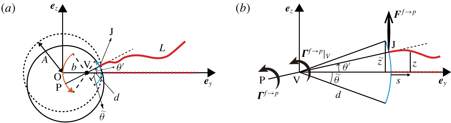
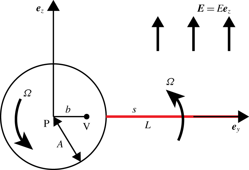
 $\hat{\unicode[STIX]{x1D703}}=\unicode[STIX]{x03C0}/2$ without loss of generality as shown in figure 10, where the rest configuration (dashed curves) corresponds to when the particle centre P coincides with the origin O and the undeformed filament is aligned in the
 $\boldsymbol{e}_{y}$ direction. The rotational oscillation is executed about a pivot V that lies away from the origin by a dimensional distance
 $b$ on the
 $y$-axis, where
 $\unicode[STIX]{x1D6FD}=b/L$; the dimensional distance between V and J is
 $d=A-b$, so similarly
 $$\begin{eqnarray}\unicode[STIX]{x1D6FF}=d/L=\unicode[STIX]{x1D6FC}-\unicode[STIX]{x1D6FD}.\end{eqnarray}$$
The particle centre P (respectively filament base J) follows a trajectory of a circular arc that is centred at V and of radius  $b$ (respectively
 $d$); both trajectories are symmetric about the
 $y$-axis. Note that
 $\unicode[STIX]{x1D6FD}$ is an unknown that is to be determined.
(a) Schematic of the model problem: a composite object of a sphere and a filament undergoes a rotational oscillation. The particle centre P and joint (filament base) J rotate periodically along circular arcs of radius  $b$ and
 $d=A-b$, respectively. V denotes their common pivot point. (b) Zoom-in on the circular arc trajectory of the joint, showing the difference between the torque
 $\unicode[STIX]{x1D71E}^{f\rightarrow p}|_{V}$ with respect to the pivot V and
 $\unicode[STIX]{x1D71E}^{f\rightarrow p}$ to the particle centre P.

Near the onset of instability, the amplitude  $\tilde{\unicode[STIX]{x1D703}}(t)$ varies much more slowly than the oscillation of
 $\unicode[STIX]{x1D703}^{\prime }$, viz.
 $\unicode[STIX]{x1D70E}_{r}\ll \unicode[STIX]{x1D70E}_{i}$. This allows us to assume that the amplitude
 $\tilde{\unicode[STIX]{x1D703}}=\unicode[STIX]{x1D6E9}\exp (\unicode[STIX]{x1D70E}_{r}t)$ is quasi-steady, namely,
 $\unicode[STIX]{x1D703}^{\prime }$ at a particular time
 $t_{0}$ can be approximated by
 $$\begin{eqnarray}\unicode[STIX]{x1D703}^{\prime }=\unicode[STIX]{x1D6E9}\exp (\unicode[STIX]{x1D70E}_{r}t_{0})\exp (\text{i}\unicode[STIX]{x1D70E}_{i}t),\end{eqnarray}$$
as an instantaneous configuration of a periodic signal with a prescribed amplitude  $\unicode[STIX]{x1D6E9}\exp (\unicode[STIX]{x1D70E}_{r}t_{0})$ and frequency
 $\unicode[STIX]{x1D70E}_{i}$. This set-up resembles the theoretical framework developed to address the so-called elastohydrodynamic problem II (Wiggins & Goldstein Reference Wiggins and Goldstein1998; Wiggins et al. Reference Wiggins, Riveline, Ott and Goldstein1998) of a filament with one of its ends undergoing straight, oscillatory translation. We adapt that framework for our configuration, whereas the filament end oscillates on a circular arc instead of on a straight path, as shown in figure 10(b). Because the filament undergoes small-amplitude deformation,
 $|z_{y}|\ll 1$ and its tangent vector
 $\boldsymbol{r}_{s}\approxeq \boldsymbol{e}_{y}$. We also assume
 $T(s)\equiv 0$. The position
 $\boldsymbol{r}(t,s)$ of the filament centreline is
 $\boldsymbol{r}(s)=(\unicode[STIX]{x1D6FC}+s)\boldsymbol{e}_{y}+z(t,s)\boldsymbol{e}_{z}$. The horizontal displacement of the filament base is of order
 $O(\tilde{\unicode[STIX]{x1D703}}^{2})$ and can be neglected because
 $|\unicode[STIX]{x1D703}^{\prime }|\leqslant |\tilde{\unicode[STIX]{x1D703}}|\ll 1$. The base’s vertical oscillation is prescribed as
 $$\begin{eqnarray}z(t)|_{s=0}=\unicode[STIX]{x1D6FF}\sin \unicode[STIX]{x1D703}^{\prime }\approxeq \unicode[STIX]{x1D6FF}\unicode[STIX]{x1D703}^{\prime }=\unicode[STIX]{x1D6FF}\tilde{\unicode[STIX]{x1D703}}\exp (\text{i}\unicode[STIX]{x1D70E}_{i}t),\end{eqnarray}$$
where  $\unicode[STIX]{x1D6FF}\tilde{\unicode[STIX]{x1D703}}$ represents the oscillation amplitude. Following Wiggins & Goldstein (Reference Wiggins and Goldstein1998) and Wiggins et al. (Reference Wiggins, Riveline, Ott and Goldstein1998), the deflection of the filament is expressed by
 $$\begin{eqnarray}z(s)=\unicode[STIX]{x1D6FF}\tilde{\unicode[STIX]{x1D703}}\exp (\text{i}\unicode[STIX]{x1D70E}_{i}t)h(s,{\mathcal{L}}),\end{eqnarray}$$
where
 $$\begin{eqnarray}{\mathcal{L}}^{4}=\frac{\bar{\unicode[STIX]{x1D707}}\unicode[STIX]{x1D70E}_{i}}{-1-2\log \unicode[STIX]{x1D716}_{sl}}\end{eqnarray}$$
and  $h$ is a sum of four solutions
 $$\begin{eqnarray}h(s,{\mathcal{L}})=c_{1}\unicode[STIX]{x1D709}^{\text{i}s}+c_{2}\unicode[STIX]{x1D709}^{-s}+c_{3}\unicode[STIX]{x1D709}^{-\text{i}s}+c_{4}\unicode[STIX]{x1D709}^{s},\end{eqnarray}$$
with
 $$\begin{eqnarray}\displaystyle & \displaystyle z_{0}=\exp (-\text{i}\unicode[STIX]{x03C0}/8), & \displaystyle\end{eqnarray}$$
 $$\begin{eqnarray}\displaystyle & \displaystyle \unicode[STIX]{x1D709}=\exp (z_{0}{\mathcal{L}}). & \displaystyle\end{eqnarray}$$
 $c_{i}$ need to be determined by the BCs at the filament ends. In contrast to Wiggins & Goldstein (Reference Wiggins and Goldstein1998) and Wiggins et al. (Reference Wiggins, Riveline, Ott and Goldstein1998) treating
 $z(s)$ as a real variable, we consider a complex
 $z(s)$. This allows us to obtain the complex torque consistent with the complex nature of the torque balance, equation (4.4).
The BCs for  $h(s)$ at the free end
 $s=1$ are
 $h_{ss}=h_{sss}=0$. At the clamped end
 $s=0$,
 $h=1$ as a Dirichlet BC corresponding to the prescribed displacement; the other BC is more subtle. Because the filament orientation is orthogonal to the circular arc (see figure 10b), we have
 $$\begin{eqnarray}z_{s}=\sin \unicode[STIX]{x1D703}^{\prime }\approxeq \unicode[STIX]{x1D703}^{\prime }=\tilde{\unicode[STIX]{x1D703}}\exp (\text{i}\unicode[STIX]{x1D70E}_{i}t).\end{eqnarray}$$
By substituting equation (4.8) into (4.12), we obtain the BC
 $$\begin{eqnarray}h_{s}|_{s=0}=1/\unicode[STIX]{x1D6FF},\end{eqnarray}$$
where  $\unicode[STIX]{x1D6FF}$ is defined in (4.5). Knowing all the BCs of
 $h(s)$, we compute the four coefficients
 $$\begin{eqnarray}\displaystyle & \displaystyle c_{1}=\frac{(1+\text{i})[((1-\text{i})\unicode[STIX]{x1D709}^{1+\text{i}}-\text{i}\unicode[STIX]{x1D709}^{2}+1)\unicode[STIX]{x1D6FF}\log \unicode[STIX]{x1D709}-(1+\text{i})\unicode[STIX]{x1D709}^{1+\text{i}}-\text{i}\unicode[STIX]{x1D709}^{2}-1]}{2\unicode[STIX]{x1D6EC}\unicode[STIX]{x1D6FF}\log \unicode[STIX]{x1D709}}, & \displaystyle\end{eqnarray}$$
 $$\begin{eqnarray}\displaystyle & \displaystyle c_{2}=\frac{(1+\text{i})\unicode[STIX]{x1D709}[(-\text{i}\unicode[STIX]{x1D709}^{1+2\text{i}}+(1-\text{i})\unicode[STIX]{x1D709}^{\text{i}}+\unicode[STIX]{x1D709})\unicode[STIX]{x1D6FF}\log \unicode[STIX]{x1D709}-\unicode[STIX]{x1D709}^{1+2\text{i}}+(-1+\text{i})\unicode[STIX]{x1D709}^{\text{i}}+\text{i}\unicode[STIX]{x1D709}]}{2\unicode[STIX]{x1D6EC}\unicode[STIX]{x1D6FF}\log \unicode[STIX]{x1D709}},\quad & \displaystyle\end{eqnarray}$$
 $$\begin{eqnarray}\displaystyle & \displaystyle c_{3}=\frac{(1+\text{i})\unicode[STIX]{x1D709}^{\text{i}}[(\unicode[STIX]{x1D709}^{2+\text{i}}-\text{i}\unicode[STIX]{x1D709}^{\text{i}}+(1-\text{i})\unicode[STIX]{x1D709})\unicode[STIX]{x1D6FF}\log \unicode[STIX]{x1D709}+\unicode[STIX]{x1D709}^{2+\text{i}}+\text{i}\unicode[STIX]{x1D709}^{\text{i}}+(1+\text{i})\unicode[STIX]{x1D709}]}{2\unicode[STIX]{x1D6EC}\unicode[STIX]{x1D6FF}\log \unicode[STIX]{x1D709}},\quad & \displaystyle\end{eqnarray}$$
 $$\begin{eqnarray}\displaystyle & \displaystyle c_{4}=\frac{(1+\text{i})(\unicode[STIX]{x1D709}^{2\text{i}}+(1-\text{i})\unicode[STIX]{x1D709}^{1+\text{i}}-\text{i})\unicode[STIX]{x1D6FF}\log (\unicode[STIX]{x1D709})+(1-\text{i})\unicode[STIX]{x1D709}^{2\text{i}}+2\unicode[STIX]{x1D709}^{1+\text{i}}+1+\text{i}}{2\unicode[STIX]{x1D6EC}\unicode[STIX]{x1D6FF}\log \unicode[STIX]{x1D709}},\quad & \displaystyle\end{eqnarray}$$
 $\unicode[STIX]{x1D6EC}=\unicode[STIX]{x1D709}^{2\text{i}}+4\unicode[STIX]{x1D709}^{1+\text{i}}+\unicode[STIX]{x1D709}^{2+2\text{i}}+\unicode[STIX]{x1D709}^{2}+1$. Considering the small-amplitude deformation, the total force
 $\boldsymbol{F}$ exerted by the filament on the clamped end is along the vertical
 $\boldsymbol{e}_{z}$ direction. The torque
 $\unicode[STIX]{x1D71E}^{f\rightarrow p}|_{V}$ with respect to the pivot V and
 $\unicode[STIX]{x1D71E}^{f\rightarrow p}$ with respect to the particle centre P are along the
 $\boldsymbol{e}_{x}$ direction, so that the corresponding components of the force and torques are
 $$\begin{eqnarray}\displaystyle & \displaystyle F_{z}^{f\rightarrow p}=\tilde{\unicode[STIX]{x1D703}}\exp (\text{i}\unicode[STIX]{x1D70E}_{i}t)\frac{\log ^{2}\unicode[STIX]{x1D709}[(1+\text{i})\unicode[STIX]{x1D6EC}_{1}\unicode[STIX]{x1D6FF}\log \unicode[STIX]{x1D709}-\text{i}\unicode[STIX]{x1D6EC}_{2}]}{\unicode[STIX]{x1D6EC}}, & \displaystyle\end{eqnarray}$$
 $$\begin{eqnarray}\displaystyle & \displaystyle \unicode[STIX]{x1D6E4}_{x}^{f\rightarrow p}|_{V}=\tilde{\unicode[STIX]{x1D703}}\exp (\text{i}\unicode[STIX]{x1D70E}_{i}t)\frac{\log \unicode[STIX]{x1D709}[(1+\text{i})\unicode[STIX]{x1D6FF}^{2}\unicode[STIX]{x1D6EC}_{1}\log ^{2}\unicode[STIX]{x1D709}-2\text{i}\unicode[STIX]{x1D6FF}\unicode[STIX]{x1D6EC}_{2}\log \unicode[STIX]{x1D709}+(-1-\text{i})\unicode[STIX]{x1D6EC}_{3}]}{\unicode[STIX]{x1D6EC}},\qquad & \displaystyle\end{eqnarray}$$
 $$\begin{eqnarray}\displaystyle \unicode[STIX]{x1D6E4}_{x}^{f\rightarrow p} & = & \displaystyle \unicode[STIX]{x1D6E4}_{x}^{f\rightarrow p}|_{V}+(\unicode[STIX]{x1D6FC}-\unicode[STIX]{x1D6FF})F_{z}^{f\rightarrow p}\nonumber\\ \displaystyle & = & \displaystyle \tilde{\unicode[STIX]{x1D703}}\exp (\text{i}\unicode[STIX]{x1D70E}_{i}t)\frac{\log \unicode[STIX]{x1D709}[(1+\text{i})\unicode[STIX]{x1D6FC}\unicode[STIX]{x1D6FF}\unicode[STIX]{x1D6EC}_{1}\log ^{2}\unicode[STIX]{x1D709}-\text{i}(\unicode[STIX]{x1D6FC}+\unicode[STIX]{x1D6FF})\unicode[STIX]{x1D6EC}_{2}\log \unicode[STIX]{x1D709}+(-1-\text{i})\unicode[STIX]{x1D6EC}_{3}]}{\unicode[STIX]{x1D6EC}},\nonumber\\ \displaystyle & & \displaystyle\end{eqnarray}$$
where
 $$\begin{eqnarray}\displaystyle & \displaystyle \unicode[STIX]{x1D6EC}_{1}=-\unicode[STIX]{x1D709}^{2\text{i}}-\text{i}\unicode[STIX]{x1D709}^{2+2\text{i}}+\unicode[STIX]{x1D709}^{2}+\text{i}, & \displaystyle\end{eqnarray}$$
 $$\begin{eqnarray}\displaystyle & \displaystyle \unicode[STIX]{x1D6EC}_{2}=(-1+\unicode[STIX]{x1D709}^{2\text{i}})(\unicode[STIX]{x1D709}^{2}-1), & \displaystyle\end{eqnarray}$$
 $$\begin{eqnarray}\displaystyle & \displaystyle \unicode[STIX]{x1D6EC}_{3}=\text{i}\unicode[STIX]{x1D709}^{2\text{i}}+\unicode[STIX]{x1D709}^{2+2\text{i}}-\text{i}\unicode[STIX]{x1D709}^{2}-1. & \displaystyle\end{eqnarray}$$
Now, let us examine the denominator,  $\unicode[STIX]{x1D6EC}$, of (4.15) whose five terms are in the form of
 $\unicode[STIX]{x1D709}^{q_{k}}$ (
 $k=1...5$), where
 $[q_{1},q_{2},q_{3},q_{4},q_{5}]=[2\text{i},1+\text{i},2+2\text{i},2,0]$. Using (4.11), we express
 $\unicode[STIX]{x1D709}^{q_{k}}$ as
 $$\begin{eqnarray}\unicode[STIX]{x1D709}^{q_{k}}=[\exp (z_{0}{\mathcal{L}})]^{q_{k}}=\unicode[STIX]{x1D701}_{k}^{{\mathcal{L}}},\end{eqnarray}$$
where  $\unicode[STIX]{x1D701}_{k}=\exp (z_{0}q_{k})$ are
 $$\begin{eqnarray}\left.\begin{array}{@{}ccl@{}}\displaystyle \unicode[STIX]{x1D701}_{1} & = & -0.59+2.09\text{i},\\ \displaystyle \unicode[STIX]{x1D701}_{2} & = & 3.17+1.9\text{i},\\ \displaystyle \unicode[STIX]{x1D701}_{3} & = & 6.4+12.05\text{i},\\ \displaystyle \unicode[STIX]{x1D701}_{4} & = & 4.57-4.4\text{i},\\ \displaystyle \unicode[STIX]{x1D701}_{5} & = & 1.\end{array}\right\}\end{eqnarray}$$
We observe that the third term  $\unicode[STIX]{x1D701}_{3}^{{\mathcal{L}}}$ is larger than the rest in magnitude when
 ${\mathcal{L}}\geqslant 1$, dominating the second largest term by one order when
 ${\mathcal{L}}\geqslant 3$. Let us assume
 ${\mathcal{L}}\geqslant 3$a priori, so that we can then approximate
 $\unicode[STIX]{x1D6EC}$ by
 $\unicode[STIX]{x1D701}_{3}^{{\mathcal{L}}}$ in (4.15). By further extracting the leading-order terms of
 $\unicode[STIX]{x1D6EC}_{1}/\unicode[STIX]{x1D6EC}$,
 $\unicode[STIX]{x1D6EC}_{2}/\unicode[STIX]{x1D6EC}$ and
 $\unicode[STIX]{x1D6EC}_{3}/\unicode[STIX]{x1D6EC}$, we attain a simplified, leading-order expression for the force and torque (denoted by
 $\;\tilde{\;}\;$)
 $$\begin{eqnarray}\displaystyle & \displaystyle \tilde{F}_{z}^{f\rightarrow p}=\tilde{\unicode[STIX]{x1D703}}\exp (\text{i}\unicode[STIX]{x1D70E}_{i}t)\log ^{2}\unicode[STIX]{x1D709}[(1-\text{i})\unicode[STIX]{x1D6FF}\log \unicode[STIX]{x1D709}-\text{i}], & \displaystyle\end{eqnarray}$$
 $$\begin{eqnarray}\displaystyle & \displaystyle \tilde{\unicode[STIX]{x1D6E4}}_{x}^{f\rightarrow p}|_{V}=\tilde{\unicode[STIX]{x1D703}}\exp (\text{i}\unicode[STIX]{x1D70E}_{i}t)\log \unicode[STIX]{x1D709}[(1-\text{i})\unicode[STIX]{x1D6FF}^{2}\log ^{2}\unicode[STIX]{x1D709}-2\text{i}\unicode[STIX]{x1D6FF}\log \unicode[STIX]{x1D709}-1-\text{i}], & \displaystyle\end{eqnarray}$$
 $$\begin{eqnarray}\displaystyle & \displaystyle \tilde{\unicode[STIX]{x1D6E4}}_{x}^{f\rightarrow p}=\tilde{\unicode[STIX]{x1D703}}\exp (\text{i}\unicode[STIX]{x1D70E}_{i}t)\log \unicode[STIX]{x1D709}[(1-\text{i})\unicode[STIX]{x1D6FC}\unicode[STIX]{x1D6FF}\log ^{2}\unicode[STIX]{x1D709}-\text{i}(\unicode[STIX]{x1D6FC}+\unicode[STIX]{x1D6FF})\log \unicode[STIX]{x1D709}-1-\text{i}]. & \displaystyle\end{eqnarray}$$
 $F_{z}^{f\rightarrow p}$, torque
 $\unicode[STIX]{x1D6E4}_{x}^{f\rightarrow p}|_{V}$ and their leading-order counterparts
 $\tilde{F}_{z}^{f\rightarrow p}$ and
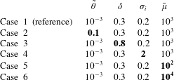
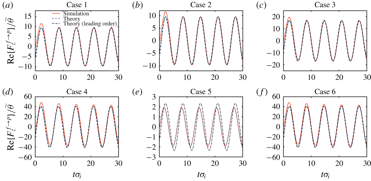
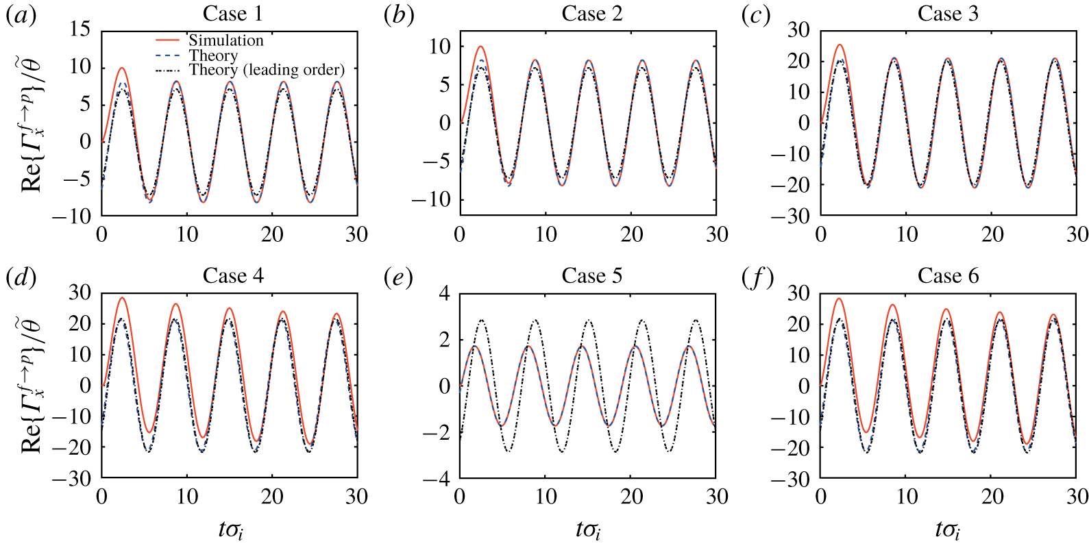
 $\tilde{\unicode[STIX]{x1D6E4}}_{x}^{f\rightarrow p}|_{V}$ are validated against the numerical results for six cases spanning a wide range of parameters relevant to our study (see table 1), where case 1 is the reference case and the other five vary a single parameter compared to case 1. Because the numerical force and torque are real quantities, the real parts of
 $F_{z}^{f\rightarrow p}$ (dashed curve) given by (4.15a), and its leading-order approximation
 $\tilde{F}_{z}^{f\rightarrow p}$ (dot-dashed curve) by (4.19a), are compared with the numerical data (solid curve) in figure 11. A similar comparison between the torques
 $\unicode[STIX]{x1D6E4}_{x}^{f\rightarrow p}$ and
 $\tilde{\unicode[STIX]{x1D6E4}}_{x}^{f\rightarrow p}|_{V}$ is shown in figure 12.
Parameters for the six cases chosen to validate numerical results against the theoretical force  $F_{z}^{f\rightarrow p}$, torque
 $\unicode[STIX]{x1D6E4}_{x}^{f\rightarrow p}|_{V}$ and their leading-order counterparts. Bold entries indicate the difference from the reference, case
 $1$.

We observe that the force  $F_{z}^{f\rightarrow p}$ and torque
 $\unicode[STIX]{x1D6E4}_{x}^{f\rightarrow p}|_{V}$ and their leading-order values agree with the numerical results quantitatively in all the cases except for case 5, where the leading-order results deviate a little from the full expression and numerical results. This disagreement results from the violation of the assumption
 ${\mathcal{L}}\geqslant 3$ used to derive the leading-order expression, where
 ${\mathcal{L}}\approx 1.25$ for case 5. This also implies that the leading-order predictions become less accurate at small
 $\bar{\unicode[STIX]{x1D707}}$ values.
Comparison between the theoretical force  $F_{z}^{f\rightarrow p}$ (dashed curves), its leading-order approximation
 $\tilde{F}_{z}^{f\rightarrow p}$ (dot-dashed curves) and the numerical results (solid curves).

Comparison between the theoretical torque  $\unicode[STIX]{x1D6E4}_{x}^{f\rightarrow p}$ (dashed curves), its leading-order approximation
 $\tilde{\unicode[STIX]{x1D6E4}}_{x}^{f\rightarrow p}$ (dot-dashed curves) and the numerical results (solid curves).

For the validation purpose,  $\unicode[STIX]{x1D6FF}=\unicode[STIX]{x1D6FC}-\unicode[STIX]{x1D6FD}$ can be prescribed. However, for the model,
 $\unicode[STIX]{x1D6FF}$ needs to be determined using the force-free condition on the particle. The particle follows a circular arc on the other side of the pivot V, the
 $z$-component of the hydrodynamic force on the particle approximated by the Stokes’s law is
 $$\begin{eqnarray}F_{z}^{h\rightarrow p}=\frac{3\text{i}}{4}\bar{\unicode[STIX]{x1D707}}\unicode[STIX]{x1D6FC}\unicode[STIX]{x1D6FD}\unicode[STIX]{x1D70E}_{i}\tilde{\unicode[STIX]{x1D703}}\exp (\text{i}\unicode[STIX]{x1D70E}_{i}t).\end{eqnarray}$$
Substituting (4.19a) and (4.20) into  $\tilde{F}_{z}^{f\rightarrow p}+F_{z}^{f\rightarrow p}=0$, we obtain
 $$\begin{eqnarray}\unicode[STIX]{x1D6FD}=\frac{4\log ^{2}\unicode[STIX]{x1D709}[1+\unicode[STIX]{x1D6FC}(\text{i}+1)\log \unicode[STIX]{x1D709}]}{3\unicode[STIX]{x1D6FC}\bar{\unicode[STIX]{x1D707}}\unicode[STIX]{x1D70E}_{i}+4(\text{i}+1)\log ^{3}\unicode[STIX]{x1D709}}.\end{eqnarray}$$
Using the leading-order torque  $\tilde{\unicode[STIX]{x1D6E4}}_{x}^{f\rightarrow p}$ (4.19c), as the left-hand side torque of (4.4) (note that the nodal line direction
 $\boldsymbol{N}=\boldsymbol{e}_{x}$ when the orientation
 $\boldsymbol{e}_{p}$ is restricted to the
 $yz$-plane), we obtain the governing equation for the transformed growth rate
 $\hat{\unicode[STIX]{x1D70E}}=\bar{\unicode[STIX]{x1D707}}\unicode[STIX]{x1D70E}$,
 $$\begin{eqnarray}\unicode[STIX]{x1D6FC}^{3}\frac{\hat{\unicode[STIX]{x1D70E}}[\hat{\unicode[STIX]{x1D70E}}-(\bar{E}^{2}-1)\unicode[STIX]{x1D705}\bar{\unicode[STIX]{x1D707}}]}{\hat{\unicode[STIX]{x1D70E}}+\unicode[STIX]{x1D705}\bar{\unicode[STIX]{x1D707}}}+\log \unicode[STIX]{x1D709}[(\text{i}-1)\unicode[STIX]{x1D6FC}(\unicode[STIX]{x1D6FC}-\unicode[STIX]{x1D6FD})\log ^{2}\unicode[STIX]{x1D709}+\text{i}(2\unicode[STIX]{x1D6FC}-\unicode[STIX]{x1D6FD})\log \unicode[STIX]{x1D709}+1+\text{i}]=0,\end{eqnarray}$$
where
 $$\begin{eqnarray}\unicode[STIX]{x1D6FD}=\frac{4\log ^{2}\unicode[STIX]{x1D709}[1+\unicode[STIX]{x1D6FC}(\text{i}+1)\log \unicode[STIX]{x1D709}]}{3\unicode[STIX]{x1D6FC}\hat{\unicode[STIX]{x1D70E}}_{i}+4(\text{i}+1)\log ^{3}\unicode[STIX]{x1D709}},\end{eqnarray}$$
where  $\log \unicode[STIX]{x1D709}$ can be written as
 $$\begin{eqnarray}\log \unicode[STIX]{x1D709}=z_{0}{\mathcal{L}}=z_{0}\left(\frac{\hat{\unicode[STIX]{x1D70E}}_{i}}{-1-2\log \unicode[STIX]{x1D716}_{sl}}\right)^{1/4}.\end{eqnarray}$$
4.3 Complex growth rates and onset of instability
We solve (4.22) to obtain the transformed growth rate  $\hat{\unicode[STIX]{x1D70E}}$, which facilitates a theoretical prediction of the onset of self-oscillatory instability. The growth rate
 $\hat{\unicode[STIX]{x1D70E}}=\hat{\unicode[STIX]{x1D70E}}_{r}+\text{i}\hat{\unicode[STIX]{x1D70E}}_{i}$ depends on
 $\unicode[STIX]{x1D6FC}$,
 $\unicode[STIX]{x1D716}_{sl}$,
 $\unicode[STIX]{x1D705}$,
 $\bar{\unicode[STIX]{x1D707}}$ and
 $E$, where we have fixed
 $\unicode[STIX]{x1D716}_{sl}$ and
 $\unicode[STIX]{x1D705}$. By writing
 $\hat{\unicode[STIX]{x1D70E}}_{i}=W^{4}$ and substituting it into (4.9), we obtain
 ${\mathcal{L}}=W/(-1-2\log \unicode[STIX]{x1D716}_{sl})^{1/4}$. Here,
 ${\mathcal{L}}$ is a positive real number, so is
 $W$. By substituting (4.23) and (4.24) into (4.22), we derive a system of two-dimensional, nonlinear polynomial equations for
 $\hat{\unicode[STIX]{x1D70E}}_{r}$ and
 $W$ (see appendix C) and obtain its roots by employing the python driver phcpy (Verschelde Reference Verschelde2013; Otto, Forbes & Verschelde Reference Otto, Forbes and Verschelde2019) of a general-purpose solver PHCpack (Verschelde Reference Verschelde1997) for polynomial systems. Because
 $\hat{\unicode[STIX]{x1D70E}}=\bar{\unicode[STIX]{x1D707}}\unicode[STIX]{x1D70E}$, we obtain the real part
 $\unicode[STIX]{x1D70E}_{r}=\hat{\unicode[STIX]{x1D70E}}_{r}/\bar{\unicode[STIX]{x1D707}}$ and imaginary part
 $\unicode[STIX]{x1D70E}_{i}=W^{4}/\bar{\unicode[STIX]{x1D707}}$ of the complex growth rate
 $\unicode[STIX]{x1D70E}$.
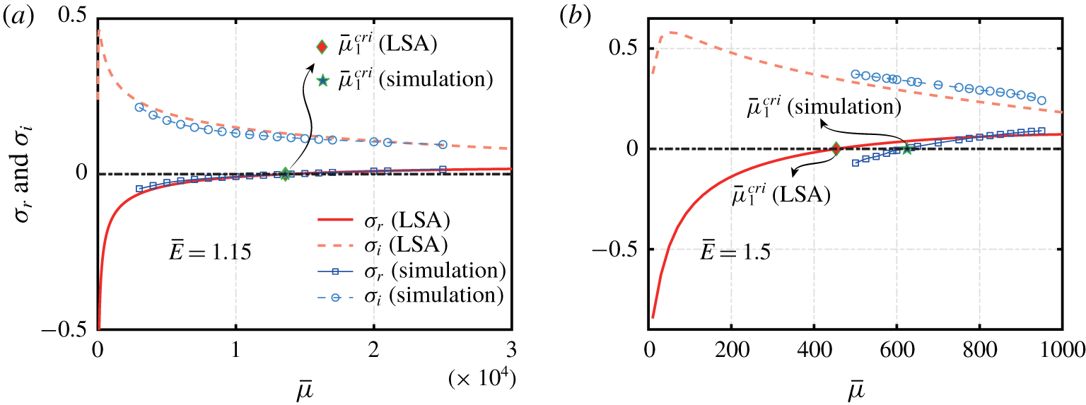
The real  $\unicode[STIX]{x1D70E}_{r}$ and imaginary
 $\unicode[STIX]{x1D70E}_{i}$ parts of the complex growth rate
 $\unicode[STIX]{x1D70E}=\unicode[STIX]{x1D70E}_{r}+\text{i}\unicode[STIX]{x1D70E}_{i}$ versus
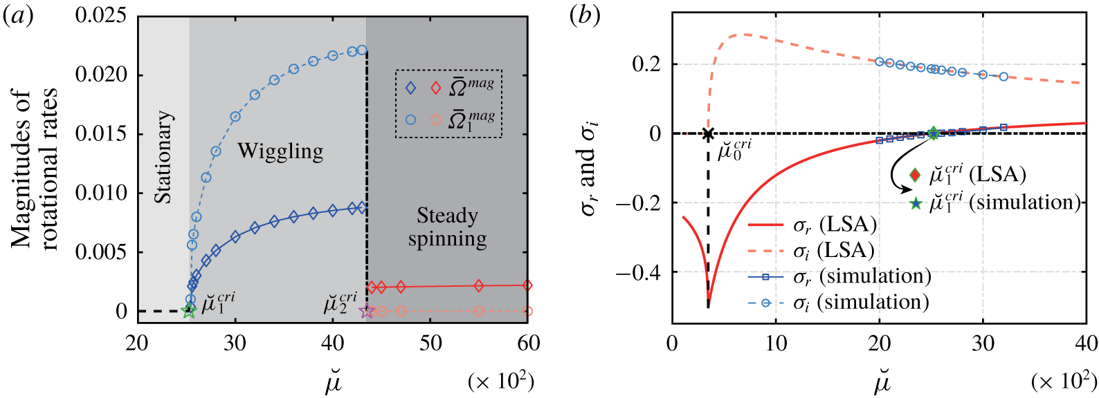
 $\bar{\unicode[STIX]{x1D707}}$ for two electric fields: (a)
 $\bar{E}=1.15$ and (b)
 $\bar{E}=1.5$, where the size ratio
 $\unicode[STIX]{x1D6FC}=0.3$. Theoretical (LSA) and numerical predictions are denoted by red curves and blue symbols, respectively. The intersection of
 $\unicode[STIX]{x1D70E}_{r}(\bar{\unicode[STIX]{x1D707}})$ with
 $\unicode[STIX]{x1D70E}=0$ gives the critical EEV value
 $\bar{\unicode[STIX]{x1D707}}_{1}^{cri}$ (indicated by diamonds and pentagrams for theoretical and numerical results, respectively) corresponding to the onset of instability.

We show  $\unicode[STIX]{x1D70E}_{r}$ and
 $\unicode[STIX]{x1D70E}_{i}$ as a function of
 $\bar{\unicode[STIX]{x1D707}}$ in figure 13 for two electric fields
 $\bar{E}=1.15$ (a) and
 $\bar{E}=1.5$ (b), where
 $\unicode[STIX]{x1D6FC}=0.3$. In both cases, the imaginary part
 $\unicode[STIX]{x1D70E}_{i}(\bar{\unicode[STIX]{x1D707}})>0$ implying that the perturbation always decays/grows in an oscillatory manner. In contrast, the real part
 $\unicode[STIX]{x1D70E}_{r}$ increases with
 $\bar{\unicode[STIX]{x1D707}}$ monotonically from negative to positive values, indicating the critical condition
 $\unicode[STIX]{x1D70E}_{r}(\bar{\unicode[STIX]{x1D707}}_{1}^{cri})=0$ of the self-oscillatory instability. When
 $\bar{\unicode[STIX]{x1D707}}$ is smaller/larger than
 $\bar{\unicode[STIX]{x1D707}}_{1}^{cri}$, the perturbation exhibits oscillatory decaying and growth. The LSA prediction of
 $(\unicode[STIX]{x1D70E}_{r},\unicode[STIX]{x1D70E}_{i})$ agrees quantitatively with the numerical counterpart for the
 $\bar{E}=1.15$ case, and qualitatively for the
 $\bar{E}=1.5$ case.
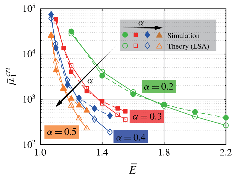
We adopt a bi-section method to determine  $\bar{\unicode[STIX]{x1D707}}_{1}^{cri}$ as a function of
 $(\bar{E},\unicode[STIX]{x1D6FC})$, as shown in figure 14. For all
 $\unicode[STIX]{x1D6FC}$ values,
 $\bar{\unicode[STIX]{x1D707}}_{1}^{cri}$ decreases monotonically with
 $\bar{E}$. The theoretical and numerical predictions agree well with each other, especially in the high
 $\bar{\unicode[STIX]{x1D707}}$ regime. The agreement degenerates with decreasing
 $\bar{\unicode[STIX]{x1D707}}$. We infer that
 ${\mathcal{L}}$ becomes smaller when
 $\bar{\unicode[STIX]{x1D707}}$ decreases, hence this disagreement is mostly attributed to violating the
 ${\mathcal{L}}\geqslant 3$ assumption of the leading-order force/torque model for the LSA.
The LSA (hollow symbols) and numerical (filled symbols) predictions of the critical EEV number  $\bar{\unicode[STIX]{x1D707}}_{1}^{cri}$ (versus
 $\bar{E}$) at which instability occurs through a Hopf bifurcation, for size ratios
 $\unicode[STIX]{x1D6FC}=0.2$ (circles), 0.3 (squares), 0.4 (diamonds) and 0.5 (triangles).

5 A minimal model to reproduce the EEH instability and self-oscillation
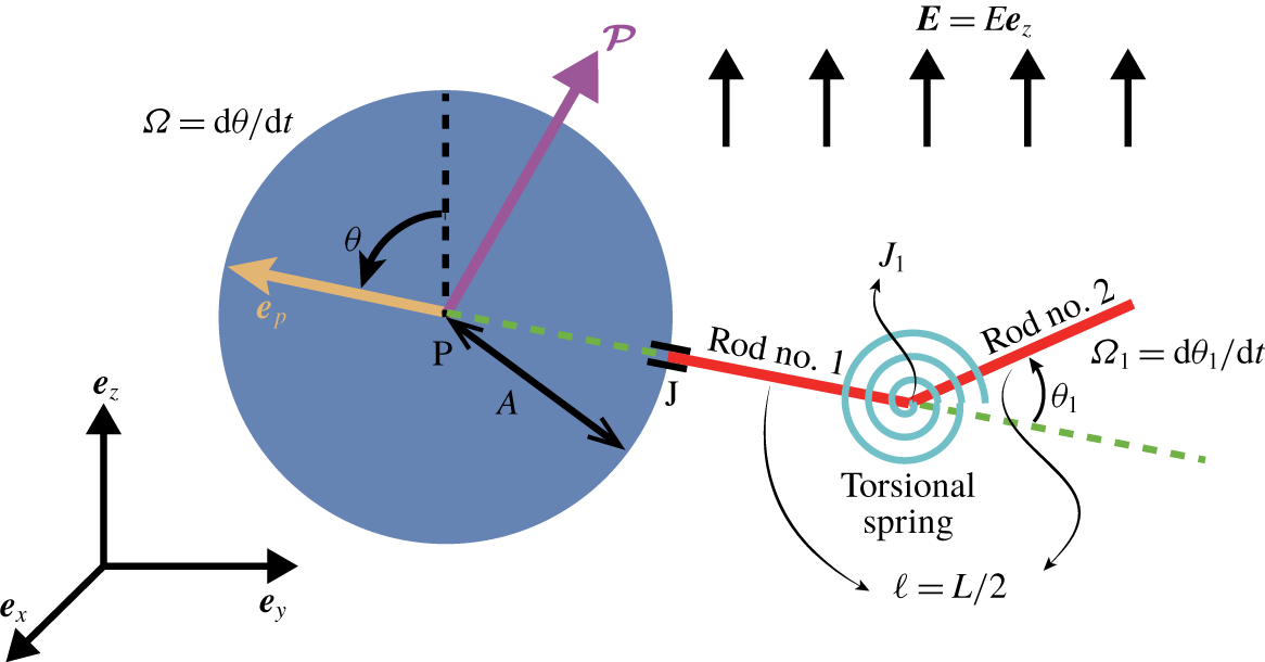
Schematic of a minimal model to reproduce the EEH instability and self-oscillation: the elastic filament is represented by two rigid rods of the same length  $\ell =L/2$ linked flexibly at
 $\text{J}_{1}$ by a torsional spring of elastic modulus
 $K$. Rod
 $\text{no.}~1$ is rigidly anchored at J. A steady, uniform electrical field
 $\boldsymbol{E}=E\boldsymbol{e}_{z}$ is applied.

To better unravel the physics underlying the EEH instability, we seek a minimal model reproducing this instability and the corresponding self-oscillation. By analogy to the multi-linker models (De Canio et al. Reference De Canio, Lauga and Goldstein2017; Ling et al. Reference Ling, Guo and Kanso2018), we replace the elastic filament by two rigid cylindrical rods numbered  $\text{no.}~1$ and
 $\text{no.}~2$ of equal length
 $\ell =L/2$ and equal radius
 $a$ of their cross-sections, which are linked at
 $\text{J}_{1}$ by a torsional spring with an elastic module of
 $K$ (see figure 15). Rod
 $\text{no.}~1$ is clamped at the sphere surface J, namely it always passes through the particle centre P, hence the displacement vectors
 $\boldsymbol{P}\boldsymbol{J}$ and
 $\boldsymbol{P}\boldsymbol{J}_{1}$ are opposite to the particle orientation
 $\boldsymbol{e}_{p}$. Rod
 $\text{no.}~2$ is oriented with respect to
 $\boldsymbol{P}\boldsymbol{J}_{1}$ by an angle
 $\unicode[STIX]{x1D703}_{1}$, which is zero when the composite system is at rest.
Similar to the original set-up, we assume that the motion of particle and the rods are restricted to the  $yz$-plane. Further, no hydrodynamic interactions between the particle and rods, or between the rods are considered. The system consists of six unknowns: the translational velocity components
 $U_{y}(t)$ and
 $U_{z}(t)$ of the particle, the rotational velocity component
 $\text{d}\unicode[STIX]{x1D703}(t)/\text{d}t=\unicode[STIX]{x1D6FA}(t)$ of the particle and
 $\text{d}\unicode[STIX]{x1D703}_{1}(t)/\text{d}t=\unicode[STIX]{x1D6FA}_{1}(t)$ of rod
 $\text{no.}~2$ with respect to rod
 $\text{no.}~1$ and the polarisation vector components
 ${\mathcal{P}}_{Q}(t)$ and
 ${\mathcal{P}}_{3}(t)$. It is worth noting that compared to the classical QR particle, this minimal configuration only incorporates one extra degree of freedom,
 $\unicode[STIX]{x1D703}_{1}$, which indicates the deformation magnitude of the torsional spring.
We first derive the hydrodynamic force exerted on rod  $\text{no.}~1$ as
 $$\begin{eqnarray}\displaystyle \boldsymbol{F}_{1}^{hydro} & = & \displaystyle \frac{2\unicode[STIX]{x03C0}\unicode[STIX]{x1D707}\ell }{c}[2\unicode[STIX]{x1D703}_{t}(2A+\ell )\cos \unicode[STIX]{x1D703}+U_{y}\cos 2\unicode[STIX]{x1D703}+3U_{y}+U_{z}\sin 2\unicode[STIX]{x1D703}]\boldsymbol{e}_{y}\nonumber\\ \displaystyle & & \displaystyle \quad +\,\frac{2\unicode[STIX]{x03C0}\unicode[STIX]{x1D707}\ell }{c}[2\unicode[STIX]{x1D703}_{t}(2A+\ell )\sin \unicode[STIX]{x1D703}+U_{y}\sin 2\unicode[STIX]{x1D703}-U_{z}\cos 2\unicode[STIX]{x1D703}+3U_{z}]\boldsymbol{e}_{z},\end{eqnarray}$$
and the torque about the particle centre P
 $$\begin{eqnarray}\unicode[STIX]{x1D71E}_{1}^{hydro}|_{P}=\frac{4\unicode[STIX]{x03C0}\unicode[STIX]{x1D707}\ell }{3c}[2\unicode[STIX]{x1D703}_{t}(3A^{2}+3A\ell +\ell ^{2})+3U_{y}(2A+\ell )\cos \unicode[STIX]{x1D703}+3U_{z}(2A+\ell )\sin \unicode[STIX]{x1D703}]\boldsymbol{e}_{x}.\end{eqnarray}$$
Likewise, the hydrodynamic force exerted on rod  $\text{no.}~2$ is
 $$\begin{eqnarray}\displaystyle \boldsymbol{F}_{2}^{hydro} & = & \displaystyle \frac{2\unicode[STIX]{x03C0}\unicode[STIX]{x1D707}\ell }{c}\left[\unicode[STIX]{x1D703}_{t}(A+\ell )\cos (\unicode[STIX]{x1D703}+2\unicode[STIX]{x1D703}_{1})+3\unicode[STIX]{x1D703}_{t}(A+\ell )\cos \unicode[STIX]{x1D703}+2\ell (\unicode[STIX]{x1D703}_{t}+\unicode[STIX]{x1D703}_{1,t})\cos (\unicode[STIX]{x1D703}+\unicode[STIX]{x1D703}_{1})\right.\nonumber\\ \displaystyle & & \displaystyle +\left.\,U_{y}\cos 2(\unicode[STIX]{x1D703}+\unicode[STIX]{x1D703}_{1})+3U_{y}+U_{z}\sin 2(\unicode[STIX]{x1D703}+\unicode[STIX]{x1D703}_{1})\right]\boldsymbol{e}_{y}\nonumber\\ \displaystyle & & \displaystyle +\,\frac{2\unicode[STIX]{x03C0}\unicode[STIX]{x1D707}\ell }{c}\left[\unicode[STIX]{x1D703}_{t}(A+\ell )\sin (\unicode[STIX]{x1D703}+2\unicode[STIX]{x1D703}_{1})+3\unicode[STIX]{x1D703}_{t}(A+\ell )\sin \unicode[STIX]{x1D703}+2\ell (\unicode[STIX]{x1D703}_{t}+\unicode[STIX]{x1D703}_{1,t})\sin (\unicode[STIX]{x1D703}+\unicode[STIX]{x1D703}_{1})\right.\nonumber\\ \displaystyle & & \displaystyle +\left.\,U_{y}\sin 2(\unicode[STIX]{x1D703}+\unicode[STIX]{x1D703}_{1})-U_{z}\cos 2(\unicode[STIX]{x1D703}+\unicode[STIX]{x1D703}_{1})+3U_{z}\right]\boldsymbol{e}_{z},\end{eqnarray}$$
and the hydrodynamic torque on rod  $\text{no.}~2$ about
 $\text{J}_{1}$ is
 $$\begin{eqnarray}\unicode[STIX]{x1D71E}_{2}^{hydro}|_{\text{J}_{1}}=\frac{4\unicode[STIX]{x03C0}\unicode[STIX]{x1D707}\ell ^{2}}{3c}[3\unicode[STIX]{x1D703}_{t}(A+\ell )\cos \unicode[STIX]{x1D703}_{1}+2\ell (\unicode[STIX]{x1D703}_{t}+\unicode[STIX]{x1D703}_{1,t})+3U_{y}\cos (\unicode[STIX]{x1D703}+\unicode[STIX]{x1D703}_{1})+3U_{z}\sin (\unicode[STIX]{x1D703}+\unicode[STIX]{x1D703}_{1})].\end{eqnarray}$$
The torque-free condition on rod  $\text{no.}~2$ reads
 $$\begin{eqnarray}\boldsymbol{M}_{2}+\unicode[STIX]{x1D71E}_{2}^{hydro}|_{\text{J}_{1}}=\mathbf{0},\end{eqnarray}$$
where  $\boldsymbol{M}_{2}=-K\unicode[STIX]{x1D703}_{1}\boldsymbol{e}_{x}$ is the elastic moment exerted on rod
 $\text{no.}~2$ by the torsional spring. The torque balance on the whole composite system about the particle centre P is
 $$\begin{eqnarray}\unicode[STIX]{x1D71E}_{1}^{hydro}|_{P}+\underbrace{(\unicode[STIX]{x1D71E}_{2}^{hydro}|_{\text{J}_{1}}+\boldsymbol{P}\boldsymbol{J}_{1}\times \boldsymbol{F}_{2}^{hydro})}_{hydrodynamic\,torque\,on\,rod\,\text{no.}~2\text{ about P}}-\unicode[STIX]{x1D6FE}_{drag}\unicode[STIX]{x1D703}_{t}\boldsymbol{e}_{x}+\underbrace{(E_{3}{\mathcal{P}}_{Q}-E_{Q}{\mathcal{P}}_{3})\boldsymbol{e}_{x}}_{electric\,torque\,on\,the\,particle}=\mathbf{0}.\end{eqnarray}$$
We also need to impose the force-free condition on the whole composite object
 $$\begin{eqnarray}\boldsymbol{F}_{1}^{hydro}+\boldsymbol{F}_{2}^{hydro}-\unicode[STIX]{x1D6FD}_{drag}(U_{y}\boldsymbol{e}_{y}+U_{z}\boldsymbol{e}_{z})=\mathbf{0}.\end{eqnarray}$$
To close the system, we solve the governing equations (2.8b) and (2.8c) for  ${\mathcal{P}}_{Q}$ and
 ${\mathcal{P}}_{3}$, where the second term
 $-(\unicode[STIX]{x2202}\unicode[STIX]{x1D713}/\unicode[STIX]{x2202}t){\mathcal{P}}_{N}$ in (2.8b) disappears. We note that (5.5) and (5.6) indeed reflect the subtle interplay between the elastic, electric and hydrodynamic torques, which lead to the EEH instability-induced self-oscillation.
5.1 Non-dimensionalisation of the minimal model
We use the same characteristic scales as the original particle–filament configuration (see § 2) to non-dimensionalise (5.5), (5.6) and (5.7), except that we substitute  $D$ by
 $KL$, resulting in a slightly modified EEV parameter
 $$\begin{eqnarray}\breve{\unicode[STIX]{x1D707}}=\frac{8\unicode[STIX]{x03C0}\unicode[STIX]{x1D707}L^{3}}{K\unicode[STIX]{x1D70F}_{s}},\end{eqnarray}$$
to be distinguished from  $\bar{\unicode[STIX]{x1D707}}$ defined by equation (2.11) for the original set-up. The dimensionless governing equations for
 $\bar{U}_{y}(\bar{t})$,
 $\bar{U}_{z}(\bar{t})$,
 $\unicode[STIX]{x1D703}(\bar{t})$ and
 $\unicode[STIX]{x1D703}_{1}(\bar{t})$ are
 $$\begin{eqnarray}\displaystyle & & \displaystyle (7\unicode[STIX]{x1D6FC}+5/2)\bar{\unicode[STIX]{x1D6FA}}\cos \unicode[STIX]{x1D703}+\bar{\unicode[STIX]{x1D6FA}}(\unicode[STIX]{x1D6FC}+1/2)\cos (\unicode[STIX]{x1D703}+2\unicode[STIX]{x1D703}_{1})+(\bar{\unicode[STIX]{x1D6FA}}+\bar{\unicode[STIX]{x1D6FA}}_{1})\cos (\unicode[STIX]{x1D703}+\unicode[STIX]{x1D703}_{1})\nonumber\\ \displaystyle & & \displaystyle \quad +\,\bar{U}_{y}[\cos 2\unicode[STIX]{x1D703}+\cos 2(\unicode[STIX]{x1D703}+\unicode[STIX]{x1D703}_{1})-6\unicode[STIX]{x1D6FC}c+6]+\bar{U}_{z}[\sin 2\unicode[STIX]{x1D703}+\sin 2(\unicode[STIX]{x1D703}+\unicode[STIX]{x1D703}_{1})]=0,\end{eqnarray}$$
 $$\begin{eqnarray}\displaystyle & & \displaystyle \left(7\unicode[STIX]{x1D6FC}+5/2\right)\bar{\unicode[STIX]{x1D6FA}}\sin \unicode[STIX]{x1D703}+\bar{\unicode[STIX]{x1D6FA}}(\unicode[STIX]{x1D6FC}+1/2)\sin (\unicode[STIX]{x1D703}+2\unicode[STIX]{x1D703}_{1})+(\bar{\unicode[STIX]{x1D6FA}}+\bar{\unicode[STIX]{x1D6FA}}_{1})\sin (\unicode[STIX]{x1D703}+\unicode[STIX]{x1D703}_{1})\nonumber\\ \displaystyle & & \displaystyle \quad +\,\bar{U}_{z}[-\cos 2\unicode[STIX]{x1D703}-\cos 2\left(\unicode[STIX]{x1D703}+\unicode[STIX]{x1D703}_{1}\right)-6\unicode[STIX]{x1D6FC}c+6]+\bar{U}_{y}[\sin 2\unicode[STIX]{x1D703}+\sin 2(\unicode[STIX]{x1D703}+\unicode[STIX]{x1D703}_{1})]=0,\end{eqnarray}$$
 $$\begin{eqnarray}\displaystyle & & \displaystyle \frac{\breve{\unicode[STIX]{x1D707}}}{24}\left[3\bar{\unicode[STIX]{x1D6FA}}(\unicode[STIX]{x1D6FC}+1/2)\cos \unicode[STIX]{x1D703}_{1}+\bar{\unicode[STIX]{x1D6FA}}+\bar{\unicode[STIX]{x1D6FA}}_{1}+3\bar{U}_{y}\cos (\unicode[STIX]{x1D703}+\unicode[STIX]{x1D703}_{1})+3\bar{U}_{z}\sin (\unicode[STIX]{x1D703}+\unicode[STIX]{x1D703}_{1})\right]-c\unicode[STIX]{x1D703}_{1}=0,\nonumber\\ \displaystyle & & \displaystyle\end{eqnarray}$$
 $$\begin{eqnarray}\displaystyle & & \displaystyle \frac{\breve{\unicode[STIX]{x1D707}}}{24}\left\{(21\unicode[STIX]{x1D6FC}^{2}+15\unicode[STIX]{x1D6FC}+13/4)\bar{\unicode[STIX]{x1D6FA}}+3(\unicode[STIX]{x1D6FC}+1/2)(\bar{\unicode[STIX]{x1D6FA}}+\bar{\unicode[STIX]{x1D6FA}}_{1})\cos \unicode[STIX]{x1D703}_{1}\right.\nonumber\\ \displaystyle & & \displaystyle +\,3(7\unicode[STIX]{x1D6FC}+5/2)(\bar{U}_{y}\cos \unicode[STIX]{x1D703}+\bar{U}_{z}\sin \unicode[STIX]{x1D703})\nonumber\\ \displaystyle & & \displaystyle +\,3(\unicode[STIX]{x1D6FC}+1/2)\cos 2\unicode[STIX]{x1D703}_{1}[(\unicode[STIX]{x1D6FC}+1/2)\bar{\unicode[STIX]{x1D6FA}}+\bar{U}_{y}\cos \unicode[STIX]{x1D703}+\bar{U}_{z}\sin \unicode[STIX]{x1D703}]\nonumber\\ \displaystyle & & \displaystyle +\,\left.3(\unicode[STIX]{x1D6FC}+1/2)\sin 2\unicode[STIX]{x1D703}_{1}(\bar{U}_{z}\cos \unicode[STIX]{x1D703}-\bar{U}_{y}\sin \unicode[STIX]{x1D703})\right\}\nonumber\\ \displaystyle & & \displaystyle +\,c\unicode[STIX]{x1D703}_{1}-c\bar{\unicode[STIX]{x1D702}}\bar{\unicode[STIX]{x1D6FA}}+c\bar{E}(\bar{{\mathcal{P}}}_{Q}\cos \unicode[STIX]{x1D703}-\bar{{\mathcal{P}}}_{3}\sin \unicode[STIX]{x1D703})=0,\end{eqnarray}$$
 $c=1+2\log \unicode[STIX]{x1D716}_{sl}$ and
 $\bar{\unicode[STIX]{x1D702}}=\unicode[STIX]{x1D6FC}^{3}\breve{\unicode[STIX]{x1D707}}$ as given by (2.16) and (2.10), respectively.
The dimensionless equations for  $\bar{{\mathcal{P}}}_{Q}$ and
 $\bar{{\mathcal{P}}}_{3}$ are
 $$\begin{eqnarray}\displaystyle & \displaystyle \frac{\unicode[STIX]{x2202}\bar{{\mathcal{P}}}_{Q}}{\unicode[STIX]{x2202}\bar{t}}=-\unicode[STIX]{x1D705}(\bar{{\mathcal{P}}}_{Q}+\unicode[STIX]{x1D705}\bar{\unicode[STIX]{x1D702}}\bar{E}\sin \unicode[STIX]{x1D703}), & \displaystyle\end{eqnarray}$$
 $$\begin{eqnarray}\displaystyle & \displaystyle \frac{\unicode[STIX]{x2202}\bar{{\mathcal{P}}}_{3}}{\unicode[STIX]{x2202}\bar{t}}=-\unicode[STIX]{x1D705}(\bar{{\mathcal{P}}}_{3}+\unicode[STIX]{x1D705}\bar{\unicode[STIX]{x1D702}}\bar{E}\cos \unicode[STIX]{x1D703}), & \displaystyle\end{eqnarray}$$
 $\bar{t}=0$
 $$\begin{eqnarray}\displaystyle & \displaystyle \bar{{\mathcal{P}}}_{Q}(\bar{t}=0)=\frac{\bar{\unicode[STIX]{x1D702}}\unicode[STIX]{x1D705}^{2}\bar{E}\sin \unicode[STIX]{x1D703}}{\unicode[STIX]{x1D705}-(R-1)/(S-1)}, & \displaystyle\end{eqnarray}$$
 $$\begin{eqnarray}\displaystyle & \displaystyle \bar{{\mathcal{P}}}_{3}(\bar{t}=0)=\frac{\bar{\unicode[STIX]{x1D702}}\unicode[STIX]{x1D705}^{2}\bar{E}\cos \unicode[STIX]{x1D703}}{\unicode[STIX]{x1D705}-(R-1)/(S-1)}. & \displaystyle\end{eqnarray}$$
5.2 Numerical and theoretical (LSA) results of the minimal model
(a) Numerical results of the rotational velocity magnitudes of the minimal model versus  $\breve{\unicode[STIX]{x1D707}}$ by solving equations (5.9) and (5.10), where
 $(\bar{E},\unicode[STIX]{x1D6FC})=(1.5,0.3)$; diamonds and circles denote those of the particle and rod
 $\text{no.}~2$, respectively.
 $\breve{\unicode[STIX]{x1D707}}_{1}^{cri}$ and
 $\breve{\unicode[STIX]{x1D707}}_{2}^{cri}$ separate the three
 $\breve{\unicode[STIX]{x1D707}}$-dependent regimes: stationary, wiggling (blue) and steady spinning (red). (b) LSA (red) and numerical (blue) results of the real
 $\unicode[STIX]{x1D70E}_{r}$ and imaginary
 $\unicode[STIX]{x1D70E}_{i}$ parts of the complex growth rate
 $\unicode[STIX]{x1D70E}$ versus
 $\breve{\unicode[STIX]{x1D707}}$, where
 $(\bar{E},\unicode[STIX]{x1D6FC})=(1.5,0.3)$.
 $\breve{\unicode[STIX]{x1D707}}_{0}^{cri}$ distinguishes whether the perturbations decay monotonically when
 $\breve{\unicode[STIX]{x1D707}}<\breve{\unicode[STIX]{x1D707}}_{0}^{cri}$ or in an oscillatory manner when
 $\breve{\unicode[STIX]{x1D707}}_{0}^{cri}<\breve{\unicode[STIX]{x1D707}}<\breve{\unicode[STIX]{x1D707}}_{1}^{cri}$.

We solve (5.9) and (5.10) numerically using the MATLAB solver ‘ode15s’ for ordinary differential equations. Fixing the electric field  $\bar{E}=1.5$ and size ratio
 $\unicode[STIX]{x1D6FC}=0.3$, we show in figure 16(a) the
 $\breve{\unicode[STIX]{x1D707}}$-dependent magnitudes
 $\bar{\unicode[STIX]{x1D6FA}}^{mag}$ and
 $\bar{\unicode[STIX]{x1D6FA}}_{1}^{mag}$ of the rotational velocities of the particle and rod
 $\text{no.}~2$, respectively, when the minimal composite object reaches its equilibrium configuration. This simple model reproduces the three characteristic behaviours of the original particle–filament system: stationary (
 $\breve{\unicode[STIX]{x1D707}}<\breve{\unicode[STIX]{x1D707}}_{1}^{cri}\approx 2513$), wiggling (
 $\breve{\unicode[STIX]{x1D707}}_{1}^{cri}<\breve{\unicode[STIX]{x1D707}}<\breve{\unicode[STIX]{x1D707}}_{2}^{cri}\approx 4300$) and steady spinning (
 $\breve{\unicode[STIX]{x1D707}}>\breve{\unicode[STIX]{x1D707}}_{2}^{cri}$). In the spinning state,
 $\bar{\unicode[STIX]{x1D6FA}}_{1}^{mag}=|\text{d}\unicode[STIX]{x1D703}_{1}/\text{d}\bar{t}|=0$ reflects a time-independent angle
 $\unicode[STIX]{x1D703}_{1}$ between the two rods, which adopt a steady ‘deformed’ configuration representing a minimal model of the deformed filament.
Conducting an LSA for this minimal model, we find the closed-form expression of the complex growth rate  $\unicode[STIX]{x1D70E}=\unicode[STIX]{x1D70E}_{r}+\text{i}\unicode[STIX]{x1D70E}_{i}$ (see appendix D for details). The theoretical values of
 $\unicode[STIX]{x1D70E}_{r,i}$ versus
 $\breve{\unicode[STIX]{x1D707}}$ in case of
 $(\bar{E},\unicode[STIX]{x1D6FC})=(1.5,0.3)$ are depicted in figure 16(b), as well as their numerical counterparts in the near
 $\breve{\unicode[STIX]{x1D707}}_{1}^{cri}$ regime. The theoretical and numerical values of both
 $\unicode[STIX]{x1D70E}_{r}$ and
 $\unicode[STIX]{x1D70E}_{i}$ almost lie on top of each other, consequently, their predictions of
 $\breve{\unicode[STIX]{x1D707}}_{1}^{cri}$ (when
 $\unicode[STIX]{x1D70E}_{r}=0$) agree. This superior agreement to the particle–filament system (figure 13) is expected, because the minimal model does not require an approximate model (see § 4.2) for the elastic torque as the original case.
The LSA also indicates the emergence of another subtle critical EEV number  $\breve{\unicode[STIX]{x1D707}}_{0}^{cri}\approx 345$ (black cross in figure 16b): when
 $\breve{\unicode[STIX]{x1D707}}<\breve{\unicode[STIX]{x1D707}}_{0}^{cri}$, the real part
 $\unicode[STIX]{x1D70E}_{r}$ of the growth rate is negative, accompanying a zero imaginary part, thus the perturbations diminish to zero monotonically; when
 $\breve{\unicode[STIX]{x1D707}}_{0}^{cri}<\breve{\unicode[STIX]{x1D707}}<\breve{\unicode[STIX]{x1D707}}_{1}^{cri}$,
 $\unicode[STIX]{x1D70E}_{r}<0$ but
 $\unicode[STIX]{x1D70E}_{i}>0$, the perturbations also die out but in a an oscillatory fashion. The former case corresponds to the non-negative quantity
 $\unicode[STIX]{x1D6F4}$ inside the square-root operator in (D 3) that naturally yields real solutions for
 $\unicode[STIX]{x1D70E}$ only. A similar structure of the solutions of
 $\unicode[STIX]{x1D70E}$ was reported in De Canio et al. (Reference De Canio, Lauga and Goldstein2017). Since the current work mainly addresses the EEH instability-induced self-oscillation, we do not pursue a detailed investigation in this stable, stationary regime.
6 Conclusions and discussion
Standard biomimetic practises commonly rely on an oscillating magnetic or electric field to produce the oscillatory motion of slender artificial structures. In contrast, we propose a strategy to achieve self-oscillation of artificial structures based on a time-independent, uniform electric field. By formulating and numerically solving an elasto-electrohydrodynamic problem, this concept is illustrated by oscillating a composite object consisting of a weakly conducting dielectric spherical particle and an elastic filament immersed in a dielectric solvent.
Our strategy is grounded in the QR electrohydrodynamic instability phenomenon indicating that a weakly conducting dielectric particle suspended in a dielectric liquid of higher conductivity can undergo spontaneous rotation under a sufficiently strong DC electric field. For an individual spherical particle, this instability emerges through a supercritical pitchfork bifurcation resulting in steady rotation (Jones Reference Jones1984). By incorporating an elastic filament, we transform the pitchfork bifurcation into a Hopf bifurcation through which a self-oscillatory instability occurs (Zhu & Stone Reference Zhu and Stone2019). This transformation is attributed to the elasto-viscous response of the filament providing an elastic torque to balance the electric and hydrodynamic torques. The elastic torque is in phase with the rotational velocity of the particle at certain time periods (see figure 9b). This in-phase behaviour results in negative damping (or positive feedback), hence leading to the onset of linear instability (Jenkins Reference Jenkins2013). We comment that such a transition from pitchfork to Hopf bifurcation was also identified by Tsebers (Reference Tsebers1980) who observed oscillatory QR of ellipsoidal particles attributed to their anisotropic electric properties. It is also worth mentioning that the QR instability was utilised to study suspensions of artificial swimmers made of QR particles that achieved locomotion by rolling near a rigid solid boundary (Bricard et al. Reference Bricard, Caussin, Desreumaux, Dauchot and Bartolo2013). In addition, the recent work of Das & Lauga (Reference Das and Lauga2019) shows theoretically and numerically that a dielectric particle with particular geometrical asymmetry (e.g. a helix) under a DC electric field is able to convert QR into spontaneous translation in an unbounded domain.
We next recall the original experiments conducted by Quincke (Reference Quincke1896), where the particle was hung by a silk thread and hence the particle rotated in the direction along the orientation of the thread. Quincke also noted an oscillatory behaviour as translated by Jones (Reference Jones1984)
‘Quincke, with his spheres tethered to silk threads, had been forced to contend with periodic rotation, first in one direction and then in the other as the silk thread wound and unwound’.
We think that the ‘wound and unwound’ motion manifested the self-oscillatory phenomenon, which is attributed to the torsional deformation of the silk thread. We speculate that Quincke probably regarded this observation as an experimental nuisance, thus did not pay attention to it nor did other researchers, except for one little-known preprint (Zaks & Shliomis Reference Zaks and Shliomis2014) that recognised and modelled this torsional oscillation by considering a QR particle hung by a thread with torsional elasticity.
In this paper, we consider only the bending stiffness of the grafted filament and the whole composite object is freely suspended in the solvent. By applying an electric field stronger than the critical value corresponding to the onset of original QR instability, the composite object exhibits three distinct behaviours depending on the EEV number  $\bar{\unicode[STIX]{x1D707}}$ (inversely proportional to the bending stiffness). When
 $\bar{\unicode[STIX]{x1D707}}\leqslant \bar{\unicode[STIX]{x1D707}}_{1}^{cri}$, the object remains stationary, corresponding to a fixed-point solution; when
 $\bar{\unicode[STIX]{x1D707}}\geqslant \bar{\unicode[STIX]{x1D707}}_{2}^{cri}$, the particle spins steadily towing a deformed filament, corresponding to an asymmetric fixed-point solution; when
 $\bar{\unicode[STIX]{x1D707}}\in (\bar{\unicode[STIX]{x1D707}}_{1}^{cri},\bar{\unicode[STIX]{x1D707}}_{2}^{cri})$, the particle oscillates and the filament wiggles, leading the object to an undulatory locomotion. More specifically, instability occurs at
 $\bar{\unicode[STIX]{x1D707}}_{1}^{cri}$ through a supercritical Hopf bifurcation, where the self-oscillatory motion represents a limit-cycle solution; at
 $\bar{\unicode[STIX]{x1D707}}_{2}^{cri}$, a secondary bifurcation appears, and the oscillatory, limit-cycle solution jumps to the steadily spinning, fixed-point solution. By fixing the EEV number
 $\bar{\unicode[STIX]{x1D707}}$, bifurcation diagrams considering the electric field strength
 $\bar{E}$ as the control parameter revealed the same three scenarios (see figure 8).
We have also examined the propulsive performance of the micro-object in the self-oscillating regime  $\bar{\unicode[STIX]{x1D707}}\in (\bar{\unicode[STIX]{x1D707}}_{1}^{cri},\bar{\unicode[STIX]{x1D707}}_{2}^{cri})$. The trajectory of the object resembles a wave propagating along a straight path. The translational velocity of the object along this path varies in
 $\bar{\unicode[STIX]{x1D707}}$ non-monotonically (see figure 7c).
Motivated by the exponential temporal growth of the rotational velocity, we performed a LSA to predict theoretically the onset of the self-oscillatory instability. We have developed an elastohydrodynamic model to account for the elastic force and torque exerted by the filament on the particle, which closely matched the numerical counterparts. Incorporating this model into a standard LSA for the original QR particle, we derived the dispersion relationship of the new EEH problem. We thus calculated the complex growth rate  $\unicode[STIX]{x1D70E}=\unicode[STIX]{x1D70E}_{r}+\text{i}\unicode[STIX]{x1D70E}_{i}$ and identified the critical EEV number
 $\bar{\unicode[STIX]{x1D707}}_{1}^{cri}$. Theoretical predictions of
 $\unicode[STIX]{x1D70E}$ (figure 13) and
 $\bar{\unicode[STIX]{x1D707}}_{1}^{cri}$ (figure 14) agree well the numerical results, especially in the large
 $\bar{\unicode[STIX]{x1D707}}$ regime. However, the agreement becomes less satisfactory when
 $\bar{\unicode[STIX]{x1D707}}$ decreases because of the violation of an assumption used in the elastohydrodynamic model.
To unravel the EEH instability mechanism, we studied a minimal model system characterised by two rigid rods linked by a torsional spring to mimic the original filament. This substitution reduces the elastic element’s number of degrees of freedom to one. Numerical and LSA results demonstrated that the minimal model could exhibit the three elasticity-dependent behaviours: stationary, wiggling and steady spinning.
Following the comments of an anonymous referee, we hereby emphasise the difference between our work and other seemingly similar studies (Manghi, Schlagberger & Netz Reference Manghi, Schlagberger and Netz2006; Coq et al. Reference Coq, du Roure, Marthelot, Bartolo and Fermigier2008; Qian, Powers & Breuer Reference Qian, Powers and Breuer2008), where a flexible slender structure (filament or rod) rotated in a viscous fluid and produced thrust because one of its ends was clamped to a constantly rotating base or actuated by a constant torque. This rotation results from forced oscillation characterised by a close correlation between the frequency of the power source and that of the resulting periodic motion. This forced-oscillatory periodic motion distinguishes itself from the self-oscillatory motion we observe, where the time-independent electric field as the power source lacks a frequency corresponding to that of the periodic motion.
The current work constrained the kinematics and electric polarisation vector of the particle to a plane in order to show a clean physical picture of the new EEH instability we identified. By removing these constraints, we anticipate the appearance of more complex and diverse three-dimensional behaviours featured by bi/multi-stability, hysteresis and even chaos (ellipsoidal particles were observed to exhibit chaotic QR (Tsebers Reference Tsebers1991)). We will report the results of the ongoing work in a future paper.
It is also worth mentioning the assumption of neglecting electrohydrodynamic effect of the filament. The electric torque exerted on a slender QR structure scales with  $a^{2}L$ (Das & Lauga Reference Das and Lauga2019), and that on a sphere scales with
 $A^{3}$ (see (B 1)). By assuming that the filament and particle have similar dielectric properties and realising
 $\unicode[STIX]{x1D6FC}=A/L=O(1)$, the ratio of the former to the latter torque is of the order of
 $\unicode[STIX]{x1D716}_{sl}^{2}$. This comparison thus justifies the assumption, which also implies that no special attention needs to be paid in this context for the experimental realisation.
In conclusion, incorporating an elastic element to manipulate the electrohydrodynamic instability, we report an elasto-electro-hydrodynamic instability and use it for engineering self-oscillation of artificial structures. We anticipate that this idea of harnessing elastic media to control and diversify the bifurcation and the corresponding instability behaviour can be generalised to other stability phenomena and systems. As a result, different emerging instability behaviours can be utilised for diverse functionalities. This concept might inspire new approaches to design soft, reconfigurable machines that can morph and adapt to the environment.
Acknowledgements
We thank Drs E. Han, L. Li, Y. Man and F. Yang, and Professors F. Gallaire, E. Nazockdast, O. S. Pak, B. Rallabandi and Y. N. Young for useful discussions. Professor T. Götz is acknowledged for sharing with us his PhD thesis. We thank the anonymous referees for their insightful comments. L.Z. thanks the Swedish Research Council for a VR International Postdoc Grant (2015-06334). We thank the NSF for support via the Princeton University Material Research Science and Engineering Center (DMR-1420541). The computer time was provided by SNIC (Swedish National Infrastructure for Computing).
Declaration of interests
The authors report no conflict of interest.
Appendix A. Numerical methods for the EEH problem
In this section, we describe the numerical methods to solve the EEH problem. For notation brevity, we remove all the bars over the unknown dimensionless variables henceforth. Following Tornberg & Shelley (Reference Tornberg and Shelley2004), we use a finite difference scheme to discretise the filament centreline by a uniform grid of  $N$ points. A typical value of
 $N=201$ is used in the simulations. Therefore, we have
 $N$ unknowns for the tension
 $T(s)$ and
 $3N$ for the coordinates
 $\boldsymbol{r}(s)=x\boldsymbol{e}_{x}+y\boldsymbol{e}_{y}+z\boldsymbol{e}_{z}$. The implementation considers a general three-dimensional motion of the filament, hence we also solve for
 $x(s)$ even though the motion is restricted to the
 $yz$-plane.
In contrast, for the restricted motion of the particle, we express its translational velocity  $\boldsymbol{U}$ and rotational velocity
 $\unicode[STIX]{x1D734}$ as
 $$\begin{eqnarray}\displaystyle & \displaystyle \boldsymbol{U}=U_{y}\boldsymbol{e}_{y}+U_{z}\boldsymbol{e}_{z}, & \displaystyle\end{eqnarray}$$
 $$\begin{eqnarray}\displaystyle & \displaystyle \unicode[STIX]{x1D734}=\unicode[STIX]{x1D6FA}\boldsymbol{e}_{x}=\unicode[STIX]{x1D703}_{t}\boldsymbol{e}_{x}, & \displaystyle\end{eqnarray}$$
 $U_{y}$,
 $U_{z}$ and
 $\unicode[STIX]{x1D6FA}=\unicode[STIX]{x1D703}_{t}$ for the particle. Another two unknowns are
 ${\mathcal{P}}_{Q}$ and
 ${\mathcal{P}}_{3}$ governed by (2.12b) and (2.12c), respectively.
At the  $(k+1)$th time step,
 $T^{k+1}(s)$ is solved based on
 $\boldsymbol{r}^{k}(s)$ at the
 $k$th time step. We then solve
 $[\boldsymbol{r}^{k+1}(s),U_{y}^{k+1},U_{z}^{k+1},\unicode[STIX]{x1D6FA}^{k+1},{\mathcal{P}}_{Q}^{k+1},{\mathcal{P}}_{3}^{k+1}]$ in a coupled way, which consists of
 $3N+5$ unknowns. We adopt this coupled strategy to accurately preserve the clamped BC of the filament base J (
 $s=0$): first, the filament base is on the particle surface; second, the tangent vector
 $\boldsymbol{r}_{s}|_{s=0}$ at the base always passes through the particle centre P. This clamped BC of the filament is different from other configurations (Guglielmini et al. Reference Guglielmini, Kushwaha, Shaqfeh and Stone2012; De Canio et al. Reference De Canio, Lauga and Goldstein2017) where the base is stationary. In our case, the filament base is right on the particle surface, and is able to translate with and rotate about the particle centre.
We use the backward Euler formulation to approximate the particle centre  $\boldsymbol{x}_{p}^{k+1}$,
 $$\begin{eqnarray}\boldsymbol{x}_{p}^{k+1}=\boldsymbol{x}_{p}^{k}+\unicode[STIX]{x0394}t\boldsymbol{U}^{k+1},\end{eqnarray}$$
where  $\unicode[STIX]{x0394}t$ is the time step. The Dirichlet BC for
 $\boldsymbol{r}|_{s=0}$, namely (2.21a) becomes
 $$\begin{eqnarray}\boldsymbol{r}^{k+1}=\boldsymbol{x}_{p}^{k}+\unicode[STIX]{x0394}t\boldsymbol{U}^{k+1}+\unicode[STIX]{x1D6FC}\boldsymbol{r}_{s}^{k+1}.\end{eqnarray}$$
Likewise, we write  $\unicode[STIX]{x1D703}^{k+1}=\unicode[STIX]{x1D703}^{k}+\unicode[STIX]{x0394}t\unicode[STIX]{x1D6FA}^{k+1}$. By assuming
 $\unicode[STIX]{x0394}t\unicode[STIX]{x1D6FA}\ll 1$, we obtain
 $$\begin{eqnarray}\displaystyle & \displaystyle \cos \unicode[STIX]{x1D703}^{k+1}\approx \cos \unicode[STIX]{x1D703}^{k}-(\unicode[STIX]{x0394}t\sin \unicode[STIX]{x1D703}^{k})\unicode[STIX]{x1D6FA}^{k+1}, & \displaystyle\end{eqnarray}$$
 $$\begin{eqnarray}\displaystyle & \displaystyle \sin \unicode[STIX]{x1D703}^{k+1}\approx \sin \unicode[STIX]{x1D703}^{k}+(\unicode[STIX]{x0394}t\cos \unicode[STIX]{x1D703}^{k})\unicode[STIX]{x1D6FA}^{k+1}. & \displaystyle\end{eqnarray}$$
 $\boldsymbol{r}_{s}^{k+1}$ at the filament base is opposite to the particle orientation
 $\boldsymbol{e}_{p}$, namely
 $\boldsymbol{r}_{s}^{k+1}=\sin \unicode[STIX]{x1D703}^{k+1}\boldsymbol{e}_{y}-\cos \unicode[STIX]{x1D703}^{k+1}\boldsymbol{e}_{z}$. Using (A 4), the discretised form of this BC is,
 $$\begin{eqnarray}\boldsymbol{r}_{s}^{k+1}-(\unicode[STIX]{x0394}t\cos \unicode[STIX]{x1D703}^{k})\unicode[STIX]{x1D6FA}^{k+1}\boldsymbol{e}_{y}-(\unicode[STIX]{x0394}t\sin \unicode[STIX]{x1D703}^{k})\unicode[STIX]{x1D6FA}^{k+1}\boldsymbol{e}_{z}=\sin \unicode[STIX]{x1D703}^{k}\boldsymbol{e}_{y}-\cos \unicode[STIX]{x1D703}^{k}\boldsymbol{e}_{z}.\end{eqnarray}$$
Combining (2.14a) and (2.23a), the discretised form for the force-free condition reads
 $$\begin{eqnarray}\displaystyle & \displaystyle -y_{sss}^{k+1}|_{s=0}+(T^{k+1}y_{s}^{k+1})|_{s=0}-3\unicode[STIX]{x1D6FC}\bar{\unicode[STIX]{x1D707}}U_{y}^{k+1}/4=0, & \displaystyle\end{eqnarray}$$
 $$\begin{eqnarray}\displaystyle & \displaystyle -z_{sss}^{k+1}|_{s=0}+(T^{k+1}z_{s}^{k+1})|_{s=0}-3\unicode[STIX]{x1D6FC}\bar{\unicode[STIX]{x1D707}}U_{z}^{k+1}/4=0. & \displaystyle\end{eqnarray}$$
 $$\begin{eqnarray}\bar{\unicode[STIX]{x1D702}}\unicode[STIX]{x1D6FA}=\bar{E}\cos \unicode[STIX]{x1D703}{\mathcal{P}}_{Q}-\bar{E}\sin \unicode[STIX]{x1D703}{\mathcal{P}}_{3}+[(\sin \unicode[STIX]{x1D703}\boldsymbol{e}_{y}-\cos \unicode[STIX]{x1D703}\boldsymbol{e}_{z})\times (\boldsymbol{r}_{ss}-\unicode[STIX]{x1D6FC}\boldsymbol{r}_{sss})]|_{s=0}.\end{eqnarray}$$
We approximate  $\unicode[STIX]{x1D703}^{k+1}$ by
 $\check{\unicode[STIX]{x1D703}}=2\unicode[STIX]{x1D703}^{k}-\unicode[STIX]{x1D703}^{k-1}$ and substitute it into (A 7), deriving the discretised torque-free condition
 $$\begin{eqnarray}\bar{\unicode[STIX]{x1D702}}\unicode[STIX]{x1D6FA}^{k+1}=\bar{E}\cos \check{\unicode[STIX]{x1D703}}{\mathcal{P}}_{Q}^{k+1}-\bar{E}\sin \check{\unicode[STIX]{x1D703}}{\mathcal{P}}_{3}^{k+1}+[(\sin \check{\unicode[STIX]{x1D703}}\boldsymbol{e}_{y}-\cos \check{\unicode[STIX]{x1D703}}\boldsymbol{e}_{z})\times (\boldsymbol{r}_{ss}^{k+1}-\unicode[STIX]{x1D6FC}\boldsymbol{r}_{sss}^{k+1})]|_{s=0}.\end{eqnarray}$$
Using the backward Euler scheme for  ${\mathcal{P}}_{Q}$ and
 ${\mathcal{P}}_{3}$, and combining equations (A 4), we find the discretised governing equations for
 ${\mathcal{P}}_{Q}$ and
 ${\mathcal{P}}_{3}$,
 $$\begin{eqnarray}\displaystyle & \displaystyle (\unicode[STIX]{x1D705}+1/\unicode[STIX]{x0394}t){\mathcal{P}}_{Q}^{k+1}+\unicode[STIX]{x1D705}^{2}\bar{\unicode[STIX]{x1D702}}\bar{E}\unicode[STIX]{x0394}t\cos \unicode[STIX]{x1D703}^{k}\unicode[STIX]{x1D6FA}^{k+1}={\mathcal{P}}_{Q}^{k}/\unicode[STIX]{x0394}t-\unicode[STIX]{x1D705}^{2}\bar{\unicode[STIX]{x1D702}}\bar{E}\sin \unicode[STIX]{x1D703}^{k}, & \displaystyle\end{eqnarray}$$
 $$\begin{eqnarray}\displaystyle & \displaystyle (\unicode[STIX]{x1D705}+1/\unicode[STIX]{x0394}t){\mathcal{P}}_{3}^{k+1}-\unicode[STIX]{x1D705}^{2}\bar{\unicode[STIX]{x1D702}}\bar{E}\unicode[STIX]{x0394}t\sin \unicode[STIX]{x1D703}^{k}\unicode[STIX]{x1D6FA}^{k+1}={\mathcal{P}}_{3}^{k}/\unicode[STIX]{x0394}t-\unicode[STIX]{x1D705}^{2}\bar{\unicode[STIX]{x1D702}}\bar{E}\cos \unicode[STIX]{x1D703}^{k}. & \displaystyle\end{eqnarray}$$
Integrating (2.18), (A 6), (A 7) and (A 9), with the four BCs equations (2.20a), (A 3) and (A 5) for  $\boldsymbol{r}^{k+1}$ generates a linear system of size
 $3N+5$. Its solution corresponds to
 $[\boldsymbol{r}^{k+1}(s),U_{y}^{k+1},U_{z}^{k+1},\unicode[STIX]{x1D6FA}^{k+1},{\mathcal{P}}_{Q}^{k+1},{\mathcal{P}}_{3}^{k+1}]$.
Appendix B. Quincke rotation of a dielectric sphere jointed with a rigid rod
Following Jones (Reference Jones1984), we derive the critical electric field required to trigger the electrohydrodynamic instability of a dielectric spherical particle grafted by a rigid rod. Let us first briefly reproduce the derivation of Jones (Reference Jones1984) for an individual particle and then extend it to our composite particle–rod configuration.
The electric torque exerted on a spherical particle of radius  $A$ about its centre P is
 $$\begin{eqnarray}\unicode[STIX]{x1D71E}^{elec}={\displaystyle \frac{6\unicode[STIX]{x03C0}\unicode[STIX]{x1D716}_{s}A^{3}E^{2}(1-R/S)\unicode[STIX]{x1D70F}_{MW}\unicode[STIX]{x1D6FA}}{\left(1+{\displaystyle \frac{2}{S}}\right)\left(1+{\displaystyle \frac{R}{2}}\right)[1+\unicode[STIX]{x1D6FA}^{2}(\unicode[STIX]{x1D70F}_{MW})^{2}]}}\boldsymbol{e}_{x}.\end{eqnarray}$$
When the particle rotates about its centre at velocity  $\unicode[STIX]{x1D6FA}\boldsymbol{e}_{x}$, the hydrodynamic torque exerted on it is
 $$\begin{eqnarray}\unicode[STIX]{x1D71E}_{par}^{hydro}=-8\unicode[STIX]{x03C0}\unicode[STIX]{x1D707}A^{3}\unicode[STIX]{x1D6FA}\boldsymbol{e}_{x}.\end{eqnarray}$$
By using the torque-free condition  $\unicode[STIX]{x1D71E}^{elec}+\unicode[STIX]{x1D71E}_{par}^{hydro}=\mathbf{0}$, we derive
 $$\begin{eqnarray}\unicode[STIX]{x1D6FA}^{2}(\unicode[STIX]{x1D70F}_{MW})^{2}={\displaystyle \frac{3\unicode[STIX]{x1D716}_{s}E^{2}(1-R/S)\unicode[STIX]{x1D70F}_{MW}}{4\unicode[STIX]{x1D707}\left(1+{\displaystyle \frac{2}{S}}\right)\left(1+{\displaystyle \frac{R}{2}}\right)}}-1.\end{eqnarray}$$
Because the left-hand side of (B 3) is non-negative for a real value of  $\unicode[STIX]{x1D6FA}$, this condition gives us the criterion of the electrical field
 $E$ above which QR instability occurs,
 $$\begin{eqnarray}E\geqslant E^{cri}=\sqrt{\frac{2\unicode[STIX]{x1D70E}_{s}\unicode[STIX]{x1D707}(R+2)^{2}}{3\unicode[STIX]{x1D716}_{s}^{2}(S-R)}}.\end{eqnarray}$$
The rotational speed of the QR particle is known based on (B 3), so that its dimensionless value is
 $$\begin{eqnarray}\bar{\unicode[STIX]{x1D6FA}}_{QR}=\unicode[STIX]{x1D705}\sqrt{\bar{E}^{2}-1},\end{eqnarray}$$
where  $\unicode[STIX]{x1D705}=(R+2)/(S+2)$ as defined in (2.3).
Schematic showing a dielectric particle of radius  $A$ connected by a rigid rod of length
 $L$ and radius
 $a$. Under a sufficiently strong electric field
 $\boldsymbol{E}=E\boldsymbol{e}_{z}$, the composite object rotates about a pivot V that lies on the centreline of rod.

Now, we adapt the above derivation to the composite particle–rod system steadily rotating at velocity  $\unicode[STIX]{x1D734}=\unicode[STIX]{x1D6FA}\boldsymbol{e}_{x}$ about an off-centre pivot point V on the
 $y$-axis (see figure 17). We choose the particle centre P as the origin of the Cartesian coordinates. Using the local SBT, the force per unit length
 $-\boldsymbol{f}_{rod}$ exerted by the fluid onto the rod at arclength
 $s$ is
 $$\begin{eqnarray}-\boldsymbol{f}_{rod}(s)=-\unicode[STIX]{x1D709}_{\bot }\unicode[STIX]{x1D6FA}\left(A-b+s\right)\boldsymbol{e}_{z},\end{eqnarray}$$
where  $\unicode[STIX]{x1D709}_{\bot }=-8\unicode[STIX]{x03C0}\unicode[STIX]{x1D707}/c=-8\unicode[STIX]{x03C0}\unicode[STIX]{x1D707}/(1+2\log \unicode[STIX]{x1D716}_{sl})$, and the total hydrodynamic force
 $\boldsymbol{F}_{rod}$ exerted on the rod is
 $$\begin{eqnarray}\boldsymbol{F}_{rod}=\int _{0}^{L}-\boldsymbol{f}_{rod}(s)\,\text{d}s=-\unicode[STIX]{x1D709}_{\bot }\unicode[STIX]{x1D6FA}[(A-b)L+L^{2}/2]\boldsymbol{e}_{z}.\end{eqnarray}$$
Simultaneously, the hydrodynamic force exerted on the translating spherical particle is  $\boldsymbol{F}_{par}=6\unicode[STIX]{x03C0}\unicode[STIX]{x1D707}Ab\unicode[STIX]{x1D6FA}\boldsymbol{e}_{z}$. Using the force-free condition
 $\boldsymbol{F}_{rod}+\boldsymbol{F}_{par}=\mathbf{0}$, we obtain
 $$\begin{eqnarray}b=\frac{\unicode[STIX]{x1D709}_{\bot }L\left(1+2\unicode[STIX]{x1D6FC}\right)}{2\left(6\unicode[STIX]{x03C0}\unicode[STIX]{x1D707}\unicode[STIX]{x1D6FC}+\unicode[STIX]{x1D709}_{\bot }\right)}.\end{eqnarray}$$
The hydrodynamic torque  $\unicode[STIX]{x1D71E}_{rod}^{hydro}$ exerted on the rod with respect to the particle centre P is
 $$\begin{eqnarray}\displaystyle \unicode[STIX]{x1D71E}_{rod}^{hydro} & = & \displaystyle \int _{0}^{L}(A+s)\boldsymbol{e}_{y}\times [-\unicode[STIX]{x1D709}_{\bot }\unicode[STIX]{x1D6FA}\left(A-b+s\right)\boldsymbol{e}_{z}]\,\text{d}s\nonumber\\ \displaystyle & = & \displaystyle -\unicode[STIX]{x1D709}_{\bot }\unicode[STIX]{x1D6FA}\boldsymbol{e}_{x}\int _{0}^{L}\left(A+s\right)\left(A-b+s\right)\text{d}s\nonumber\\ \displaystyle & = & \displaystyle -\frac{\unicode[STIX]{x1D709}_{\bot }\unicode[STIX]{x1D6FA}\boldsymbol{e}_{z}}{6}[6\left(A^{2}-Ab\right)L+3\left(2A-b\right)L^{2}+2L^{3}].\end{eqnarray}$$
Using the torque-free condition on the particle–rod system,  $\unicode[STIX]{x1D71E}^{elec}+\unicode[STIX]{x1D71E}_{par}^{hydro}+\unicode[STIX]{x1D71E}_{rod}^{hydro}=\mathbf{0}$, we obtain
 $$\begin{eqnarray}\frac{\unicode[STIX]{x1D71E}^{elec}+\unicode[STIX]{x1D71E}_{par}^{hydro}+\unicode[STIX]{x1D71E}_{rod}^{hydro}}{2\unicode[STIX]{x03C0}A^{3}\unicode[STIX]{x1D6FA}\boldsymbol{e}_{x}}={\displaystyle \frac{3\unicode[STIX]{x1D716}_{s}E^{2}\left(1-R/S\right)\unicode[STIX]{x1D70F}_{MW}}{\left(1+{\displaystyle \frac{2}{S}}\right)\left(1+{\displaystyle \frac{R}{2}}\right)\left(1+\unicode[STIX]{x1D6FA}^{2}(\unicode[STIX]{x1D70F}_{MW})^{2}\right)}}-4\unicode[STIX]{x1D707}[1+F(\unicode[STIX]{x1D6FC},\hat{\unicode[STIX]{x1D6FD}},\unicode[STIX]{x1D716}_{sl})],\end{eqnarray}$$
where
 $$\begin{eqnarray}\displaystyle & \displaystyle F(\unicode[STIX]{x1D6FC},\hat{\unicode[STIX]{x1D6FD}},\unicode[STIX]{x1D716}_{sl})=\frac{6\unicode[STIX]{x1D6FC}^{-1}(1-\hat{\unicode[STIX]{x1D6FD}}^{-1})+3\unicode[STIX]{x1D6FC}^{-2}(2-\hat{\unicode[STIX]{x1D6FD}}^{-1})+2\unicode[STIX]{x1D6FC}^{-3}}{6\left(-1-2\log \unicode[STIX]{x1D716}\right)}, & \displaystyle\end{eqnarray}$$
 $$\begin{eqnarray}\displaystyle & \displaystyle \hat{\unicode[STIX]{x1D6FD}}=A/b=\frac{2\unicode[STIX]{x1D6FC}}{4\left(2\unicode[STIX]{x1D6FC}+1\right)}[4-3\unicode[STIX]{x1D6FC}\left(1+2\log \unicode[STIX]{x1D716}_{sl}\right)]. & \displaystyle\end{eqnarray}$$
 $$\begin{eqnarray}\bar{{\mathcal{E}}}^{cri}={\mathcal{E}}^{cri}/E^{cri}=\sqrt{1+F}.\end{eqnarray}$$
The typical values of  $\bar{{\mathcal{E}}}^{cri}$ as a function of size ratio
 $\unicode[STIX]{x1D6FC}=A/L$ for
 $\unicode[STIX]{x1D716}_{sl}=0.01$ are provided in table 2.
Dimensionless critical electric field  $\bar{{\mathcal{E}}}^{cri}$ above which the composite object of a dielectric sphere of size ratio
 $\unicode[STIX]{x1D6FC}$ and a rigid rod undergoes the electrohydrodynamic instability, the slenderness
 $\unicode[STIX]{x1D716}_{sl}=0.01$.

Appendix C. Two-dimensional polynomial equations for  $\hat{\unicode[STIX]{x1D70E}}_{r}$ and $W$


We substitute (4.23) and (4.24) into (4.22). We define  $E\unicode[STIX]{x1D70E}_{p}\prime =E^{2}-1$ and
 $\unicode[STIX]{x1D710}=\left(1/-1-2\log \unicode[STIX]{x1D716}_{sl}\right)^{1/4}$ that leads to
 $\log \unicode[STIX]{x1D709}=z_{0}\unicode[STIX]{x1D710}W$. Consequently, the system of two-dimensional polynomial equations for
 $\hat{\unicode[STIX]{x1D70E}}_{r}$ and
 $W$ reads
 $$\begin{eqnarray}\displaystyle 0 & = & \displaystyle -9\hat{\unicode[STIX]{x1D70E}}_{r}^{2}W^{8}\unicode[STIX]{x1D6FC}^{5}-24\hat{\unicode[STIX]{x1D70E}}^{2}W^{7}\unicode[STIX]{x1D6FC}^{3}\unicode[STIX]{x1D710}^{3}\left(\cos \frac{3\unicode[STIX]{x03C0}}{8}+\sin \frac{3\unicode[STIX]{x03C0}}{8}\right)-32\hat{\unicode[STIX]{x1D70E}}_{r}^{2}W^{6}\unicode[STIX]{x1D6FC}^{3}\unicode[STIX]{x1D710}^{6}\sin \frac{3\unicode[STIX]{x03C0}}{4}\nonumber\\ \displaystyle & & \displaystyle -\,57\hat{\unicode[STIX]{x1D70E}}_{r}W^{11}\unicode[STIX]{x1D6FC}^{4}\unicode[STIX]{x1D710}^{3}\left(-\text{cos}\frac{3\unicode[STIX]{x03C0}}{8}+\sin \frac{3\unicode[STIX]{x03C0}}{8}\right)-2\hat{\unicode[STIX]{x1D70E}}W^{10}\unicode[STIX]{x1D6FC}^{3}\unicode[STIX]{x1D710}^{2}\left(-44\unicode[STIX]{x1D710}^{4}\cos \frac{3\unicode[STIX]{x03C0}}{4}+9\sin \frac{\unicode[STIX]{x03C0}}{4}\right)\nonumber\\ \displaystyle & & \displaystyle -\,3\hat{\unicode[STIX]{x1D70E}}_{r}W^{9}\unicode[STIX]{x1D6FC}^{2}\unicode[STIX]{x1D710}\left[3\cos \frac{\unicode[STIX]{x03C0}}{8}+3\sin \frac{\unicode[STIX]{x03C0}}{8}+8\unicode[STIX]{x1D710}^{4}\left(-\text{cos}\frac{5\unicode[STIX]{x03C0}}{8}+\sin \frac{5\unicode[STIX]{x03C0}}{8}\right)\right]\nonumber\\ \displaystyle & & \displaystyle +\,9\hat{\unicode[STIX]{x1D70E}}_{r}W^{8}\unicode[STIX]{x1D6FC}\left(-4\unicode[STIX]{x1D710}^{4}+\unicode[STIX]{x1D705}\bar{\unicode[STIX]{x1D707}}\unicode[STIX]{x1D6FC}^{4}E\unicode[STIX]{x1D70E}_{p}\prime \right)\nonumber\\ \displaystyle & & \displaystyle +\,8\hat{\unicode[STIX]{x1D70E}}_{r}W^{7}\unicode[STIX]{x1D710}^{3}\left[2\unicode[STIX]{x1D710}^{4}\left(\cos \frac{7\unicode[STIX]{x03C0}}{8}-\sin \frac{7\unicode[STIX]{x03C0}}{8}\right)+3\unicode[STIX]{x1D705}\bar{\unicode[STIX]{x1D707}}\unicode[STIX]{x1D6FC}^{4}E\unicode[STIX]{x1D70E}_{p}\prime \left(\cos \frac{3\unicode[STIX]{x03C0}}{8}+\sin \frac{3\unicode[STIX]{x03C0}}{8}\right)\right]\nonumber\\ \displaystyle & & \displaystyle +\,32\unicode[STIX]{x1D705}\bar{\unicode[STIX]{x1D707}}\hat{\unicode[STIX]{x1D70E}}_{r}W^{6}\unicode[STIX]{x1D6FC}^{3}\unicode[STIX]{x1D710}^{6}\sin \frac{3\unicode[STIX]{x03C0}}{4}E\unicode[STIX]{x1D70E}_{p}\prime \nonumber\\ \displaystyle & & \displaystyle +\,9W^{16}\unicode[STIX]{x1D6FC}^{5}+33W^{15}\unicode[STIX]{x1D6FC}^{4}\unicode[STIX]{x1D710}^{3}\!\left(\cos \frac{3\unicode[STIX]{x03C0}}{8}+\sin \frac{3\unicode[STIX]{x03C0}}{8}\right)\!+2W^{14}\unicode[STIX]{x1D6FC}^{3}\unicode[STIX]{x1D710}^{2}\left(\!9\cos \frac{\unicode[STIX]{x03C0}}{4}+\!28\unicode[STIX]{x1D710}^{4}\!\sin \frac{3\unicode[STIX]{x03C0}}{4}\!\right)\nonumber\\ \displaystyle & & \displaystyle +\,3W^{13}\unicode[STIX]{x1D6FC}^{2}\unicode[STIX]{x1D710}\left[3\cos \frac{\unicode[STIX]{x03C0}}{8}-3\sin \frac{\unicode[STIX]{x03C0}}{8}+8\unicode[STIX]{x1D710}^{4}\left(\cos \frac{5\unicode[STIX]{x03C0}}{8}+\sin \frac{5\unicode[STIX]{x03C0}}{8}\right)\right]\nonumber\\ \displaystyle & & \displaystyle +\,W^{11}\unicode[STIX]{x1D710}^{3}\left[9\unicode[STIX]{x1D705}\bar{\unicode[STIX]{x1D707}}\unicode[STIX]{x1D6FC}^{4}\left(\cos \frac{3\unicode[STIX]{x03C0}}{8}-\sin \frac{3\unicode[STIX]{x03C0}}{8}\right)+16\unicode[STIX]{x1D710}^{4}\left(\cos \frac{7\unicode[STIX]{x03C0}}{8}+\sin \frac{7\unicode[STIX]{x03C0}}{8}\right)\right.\nonumber\\ \displaystyle & & \displaystyle \left.-\,24\unicode[STIX]{x1D705}\bar{\unicode[STIX]{x1D707}}\unicode[STIX]{x1D6FC}^{4}E\unicode[STIX]{x1D70E}_{p}\prime \left(\cos \frac{3\unicode[STIX]{x03C0}}{8}-\sin \frac{3\unicode[STIX]{x03C0}}{8}\right)\right]\nonumber\\ \displaystyle & & \displaystyle -\,2\unicode[STIX]{x1D705}\bar{\unicode[STIX]{x1D707}}W^{10}\unicode[STIX]{x1D6FC}^{3}\unicode[STIX]{x1D710}^{2}\left(-12\unicode[STIX]{x1D710}^{4}\cos \frac{3\unicode[STIX]{x03C0}}{4}+9\sin \frac{\unicode[STIX]{x03C0}}{4}+16\unicode[STIX]{x1D710}^{4}E\unicode[STIX]{x1D70E}_{p}\prime \cos \frac{3\unicode[STIX]{x03C0}}{4}\right)\nonumber\\ \displaystyle & & \displaystyle +\,3\unicode[STIX]{x1D705}\bar{\unicode[STIX]{x1D707}}W^{9}\unicode[STIX]{x1D6FC}^{2}\unicode[STIX]{x1D710}\left[-3\left(\cos \frac{\unicode[STIX]{x03C0}}{8}+\sin \frac{\unicode[STIX]{x03C0}}{8}\right)+8\unicode[STIX]{x1D710}^{4}\left(\cos \frac{5\unicode[STIX]{x03C0}}{8}-\sin \frac{5\unicode[STIX]{x03C0}}{8}\right)\right]\nonumber\\ \displaystyle & & \displaystyle -\,36\unicode[STIX]{x1D705}\bar{\unicode[STIX]{x1D707}}W^{8}\unicode[STIX]{x1D6FC}\unicode[STIX]{x1D710}^{4}+16\unicode[STIX]{x1D705}\bar{\unicode[STIX]{x1D707}}W^{7}\unicode[STIX]{x1D710}^{7}\left(\cos \frac{7\unicode[STIX]{x03C0}}{8}-\sin \frac{7\unicode[STIX]{x03C0}}{8}\right),\end{eqnarray}$$
and
 $$\begin{eqnarray}\displaystyle 0 & = & \displaystyle -24\hat{\unicode[STIX]{x1D70E}}^{2}W^{7}\unicode[STIX]{x1D6FC}^{4}\unicode[STIX]{x1D710}^{3}\left(\cos \frac{3\unicode[STIX]{x03C0}}{8}-\sin \frac{3\unicode[STIX]{x03C0}}{8}\right)-32\hat{\unicode[STIX]{x1D70E}}^{2}W^{6}\unicode[STIX]{x1D6FC}^{3}\unicode[STIX]{x1D710}^{6}\cos \frac{3\unicode[STIX]{x03C0}}{4}-18\hat{\unicode[STIX]{x1D70E}}W^{12}\unicode[STIX]{x1D6FC}^{5}\nonumber\\ \displaystyle & & \displaystyle -\,57\hat{\unicode[STIX]{x1D70E}}W^{11}\unicode[STIX]{x1D6FC}^{4}\unicode[STIX]{x1D710}^{3}\left(\cos \frac{3\unicode[STIX]{x03C0}}{8}+\sin \frac{3\unicode[STIX]{x03C0}}{8}\right)-2\hat{\unicode[STIX]{x1D70E}}W^{10}\unicode[STIX]{x1D6FC}^{3}\unicode[STIX]{x1D710}^{2}\left(9\cos \frac{\unicode[STIX]{x03C0}}{4}+44\unicode[STIX]{x1D710}^{4}\sin \frac{3\unicode[STIX]{x03C0}}{4}\right)\nonumber\\ \displaystyle & & \displaystyle -\,3\hat{\unicode[STIX]{x1D70E}}W^{9}\unicode[STIX]{x1D6FC}^{2}\unicode[STIX]{x1D710}\left[3\left(\cos \frac{\unicode[STIX]{x03C0}}{8}-\sin \frac{\unicode[STIX]{x03C0}}{8}\right)+8\unicode[STIX]{x1D710}^{4}\left(\cos \frac{5\unicode[STIX]{x03C0}}{8}+\sin \frac{5\unicode[STIX]{x03C0}}{8}\right)\right]\nonumber\\ \displaystyle & & \displaystyle -\,8\hat{\unicode[STIX]{x1D70E}}_{r}W^{7}\unicode[STIX]{x1D710}^{3}\left[2\unicode[STIX]{x1D710}^{4}\left(\cos \frac{7\unicode[STIX]{x03C0}}{8}+\sin \frac{7\unicode[STIX]{x03C0}}{8}\right)-3\unicode[STIX]{x1D705}\bar{\unicode[STIX]{x1D707}}\unicode[STIX]{x1D6FC}^{4}E\unicode[STIX]{x1D70E}_{p}\prime \left(\cos \frac{3\unicode[STIX]{x03C0}}{8}-\sin \frac{3\unicode[STIX]{x03C0}}{8}\right)\right]\nonumber\\ \displaystyle & & \displaystyle +\,32\unicode[STIX]{x1D705}\bar{\unicode[STIX]{x1D707}}\hat{\unicode[STIX]{x1D70E}}_{r}W^{6}\unicode[STIX]{x1D6FC}^{3}\unicode[STIX]{x1D710}^{6}E\unicode[STIX]{x1D70E}_{p}\prime \cos \frac{3\unicode[STIX]{x03C0}}{4}\nonumber\\ \displaystyle & & \displaystyle +\,33W^{15}\unicode[STIX]{x1D6FC}^{4}\unicode[STIX]{x1D710}^{3}\left(\cos \frac{3\unicode[STIX]{x03C0}}{8}-\sin \frac{3\unicode[STIX]{x03C0}}{8}\right)+2W^{14}\unicode[STIX]{x1D6FC}^{3}\unicode[STIX]{x1D710}^{2}\left(28\unicode[STIX]{x1D710}^{4}\cos \frac{3\unicode[STIX]{x03C0}}{4}-9\sin \frac{\unicode[STIX]{x03C0}}{4}\right)\nonumber\\ \displaystyle & & \displaystyle +\,3W^{13}\unicode[STIX]{x1D6FC}^{2}\unicode[STIX]{x1D710}\left[-3\left(\cos \frac{\unicode[STIX]{x03C0}}{8}+\sin \frac{\unicode[STIX]{x03C0}}{8}\right)+8\unicode[STIX]{x1D710}^{4}\left(\cos \frac{5\unicode[STIX]{x03C0}}{8}-\sin \frac{5\unicode[STIX]{x03C0}}{8}\right)\right]\nonumber\\ \displaystyle & & \displaystyle +\,9W^{12}\unicode[STIX]{x1D6FC}\left(-4\unicode[STIX]{x1D710}^{4}+\unicode[STIX]{x1D705}\bar{\unicode[STIX]{x1D707}}\unicode[STIX]{x1D6FC}^{4}E\unicode[STIX]{x1D70E}_{p}\prime \right)\nonumber\\ \displaystyle & & \displaystyle +\,W^{11}\unicode[STIX]{x1D710}^{3}\left[-9\unicode[STIX]{x1D705}\bar{\unicode[STIX]{x1D707}}\unicode[STIX]{x1D6FC}^{4}\left(\cos \frac{3\unicode[STIX]{x03C0}}{8}+\sin \frac{3\unicode[STIX]{x03C0}}{8}\right)+16\unicode[STIX]{x1D710}^{4}\left(\cos \frac{7\unicode[STIX]{x03C0}}{8}-\sin \frac{7\unicode[STIX]{x03C0}}{8}\right)\right.\nonumber\\ \displaystyle & & \displaystyle +\,\left.24\unicode[STIX]{x1D705}\bar{\unicode[STIX]{x1D707}}\unicode[STIX]{x1D6FC}^{4}E\unicode[STIX]{x1D70E}_{p}\prime \left(\cos \frac{3\unicode[STIX]{x03C0}}{8}+\sin \frac{3\unicode[STIX]{x03C0}}{8}\right)\right]\nonumber\\ \displaystyle & & \displaystyle +\,2\unicode[STIX]{x1D705}\bar{\unicode[STIX]{x1D707}}W^{10}\unicode[STIX]{x1D6FC}^{3}\unicode[STIX]{x1D710}^{2}\left(-9\cos \frac{\unicode[STIX]{x03C0}}{4}-12\unicode[STIX]{x1D710}^{4}\sin \frac{3\unicode[STIX]{x03C0}}{4}+16\unicode[STIX]{x1D710}^{4}E\unicode[STIX]{x1D70E}_{p}\prime \sin \frac{3\unicode[STIX]{x03C0}}{4}\right)\nonumber\\ \displaystyle & & \displaystyle -\,3\unicode[STIX]{x1D705}\bar{\unicode[STIX]{x1D707}}W^{9}\unicode[STIX]{x1D6FC}^{2}\unicode[STIX]{x1D710}\left[3\left(\cos \frac{\unicode[STIX]{x03C0}}{8}-\sin \frac{\unicode[STIX]{x03C0}}{8}\right)+8\unicode[STIX]{x1D710}^{4}\left(\cos \frac{5\unicode[STIX]{x03C0}}{8}+\sin \frac{5\unicode[STIX]{x03C0}}{8}\right)\right]\nonumber\\ \displaystyle & & \displaystyle -\,16\unicode[STIX]{x1D705}\bar{\unicode[STIX]{x1D707}}W^{7}\unicode[STIX]{x1D710}^{7}\left(\cos \frac{7\unicode[STIX]{x03C0}}{8}+\sin \frac{7\unicode[STIX]{x03C0}}{8}\right).\end{eqnarray}$$
Appendix D. LSA for the minimal model
We perform LSA for the minimal model. Similar to § 4.1, the bars over the dimensionless unknown variables are dropped, unless otherwise specified. The state variables  $[\unicode[STIX]{x1D703},\unicode[STIX]{x1D703}_{1},U_{y},U_{z},{\mathcal{P}}_{Q},{\mathcal{P}}_{3}]$ are decomposed into a base state
 $[\hat{\unicode[STIX]{x1D703}},\hat{\unicode[STIX]{x1D703}}_{1},\hat{U} _{y},\hat{U} _{z},\hat{{\mathcal{P}}}_{Q},\hat{{\mathcal{P}}}_{3}]$ and a perturbation state
 $[\unicode[STIX]{x1D703}^{\prime },\unicode[STIX]{x1D703}_{1}^{\prime },U_{y}^{\prime },U_{z}^{\prime },{\mathcal{P}}_{Q}^{\prime },{\mathcal{P}}_{3}^{\prime }]$, where
 $\hat{\unicode[STIX]{x1D703}}_{1}=\hat{U} _{y}=\hat{U} _{z}=0$,
 $\hat{\unicode[STIX]{x1D703}}$ is an arbitrary value, and
 $\hat{{\mathcal{P}}}_{Q}$ and
 $\hat{{\mathcal{P}}}_{3}$ are given by (4.2). By linearising (5.9) and (5.10) with respect to the base state, we derive the linear evolution equations for the perturbative state variables,
 $$\begin{eqnarray}\left.\begin{array}{@{}c@{}}(8\unicode[STIX]{x1D6FC}+4)\displaystyle \frac{\text{d}\unicode[STIX]{x1D703}^{\prime }}{\text{d}t}\cos \hat{\unicode[STIX]{x1D703}}+{\displaystyle \frac{\text{d}\unicode[STIX]{x1D703}_{1}^{\prime }}{\text{d}t}}\cos \hat{\unicode[STIX]{x1D703}}+2(3-3\unicode[STIX]{x1D6FC}c+\cos 2\hat{\unicode[STIX]{x1D703}})U_{y}^{\prime }+2U_{z}^{\prime }\sin 2\hat{\unicode[STIX]{x1D703}}=0,\\[18.0pt] (8\unicode[STIX]{x1D6FC}+4)\displaystyle {\displaystyle \frac{\text{d}\unicode[STIX]{x1D703}^{\prime }}{\text{d}t}}\sin \hat{\unicode[STIX]{x1D703}}+\frac{\text{d}\unicode[STIX]{x1D703}_{1}^{\prime }}{\text{d}t}\sin \hat{\unicode[STIX]{x1D703}}+2(3-3\unicode[STIX]{x1D6FC}c-\cos 2\hat{\unicode[STIX]{x1D703}})U_{z}^{\prime }+2U_{y}^{\prime }\sin 2\hat{\unicode[STIX]{x1D703}}=0,\\[18.0pt] \left(3\unicode[STIX]{x1D6FC}+5/2\right)\bar{\unicode[STIX]{x1D707}}\displaystyle \frac{\text{d}\unicode[STIX]{x1D703}^{\prime }}{\text{d}t}+\bar{\unicode[STIX]{x1D707}}\displaystyle \frac{\text{d}\unicode[STIX]{x1D703}_{1}^{\prime }}{\text{d}t}+3\bar{\unicode[STIX]{x1D707}}U_{y}^{\prime }\cos \hat{\unicode[STIX]{x1D703}}+3\bar{\unicode[STIX]{x1D707}}U_{z}^{\prime }\sin \hat{\unicode[STIX]{x1D703}}-24c\unicode[STIX]{x1D703}_{1}^{\prime }=0,\\[18.0pt] (24\unicode[STIX]{x1D6FC}^{2}+21\unicode[STIX]{x1D6FC}+11/2)\bar{\unicode[STIX]{x1D707}}\displaystyle \frac{\text{d}\unicode[STIX]{x1D703}^{\prime }}{\text{d}t}+3(\unicode[STIX]{x1D6FC}+1/2)\bar{\unicode[STIX]{x1D707}}\frac{\text{d}\unicode[STIX]{x1D703}_{1}^{\prime }}{\text{d}t}+(24\unicode[STIX]{x1D6FC}+9)\bar{\unicode[STIX]{x1D707}}(U_{y}^{\prime }\cos \hat{\unicode[STIX]{x1D703}}+U_{z}^{\prime }\sin \hat{\unicode[STIX]{x1D703}})\\[18.0pt] \qquad +24c\unicode[STIX]{x1D703}_{1}^{\prime }-24c\bar{\unicode[STIX]{x1D702}}\displaystyle \frac{\text{d}\unicode[STIX]{x1D703}^{\prime }}{\text{d}t}+24c\bar{\unicode[STIX]{x1D702}}\unicode[STIX]{x1D705}\bar{E}^{2}\unicode[STIX]{x1D703}^{\prime }+24c\bar{E}{\mathcal{P}}_{Q}^{\prime }\cos \hat{\unicode[STIX]{x1D703}}-24c\bar{E}{\mathcal{P}}_{3}^{\prime }\sin \hat{\unicode[STIX]{x1D703}}=0\\[18.0pt] \displaystyle {\displaystyle \frac{\unicode[STIX]{x2202}{\mathcal{P}}_{Q}^{\prime }}{\unicode[STIX]{x2202}t}}+\unicode[STIX]{x1D705}{\mathcal{P}}_{Q}^{\prime }+\unicode[STIX]{x1D705}^{2}\bar{\unicode[STIX]{x1D702}}\bar{E}\unicode[STIX]{x1D703}^{\prime }\cos \hat{\unicode[STIX]{x1D703}}=0,\\[18.0pt] \displaystyle {\displaystyle \frac{\unicode[STIX]{x2202}{\mathcal{P}}_{3}^{\prime }}{\unicode[STIX]{x2202}t}}+\unicode[STIX]{x1D705}{\mathcal{P}}_{3}^{\prime }-\unicode[STIX]{x1D705}^{2}\bar{\unicode[STIX]{x1D702}}\bar{E}\unicode[STIX]{x1D703}^{\prime }\sin \hat{\unicode[STIX]{x1D703}}=0.\end{array}\right\}\end{eqnarray}$$
Employing the normal-mode approach as in § 4, we substitute  $[\unicode[STIX]{x1D703}^{\prime },\unicode[STIX]{x1D703}_{1}^{\prime },U_{y}^{\prime },U_{z}^{\prime },{\mathcal{P}}_{Q}^{\prime },{\mathcal{P}}_{3}^{\prime }]=[\unicode[STIX]{x1D6E9},\unicode[STIX]{x1D6E9}_{1},{\mathcal{Y}},{\mathcal{Z}},\unicode[STIX]{x1D6F7},\unicode[STIX]{x1D6F1}]\exp (\unicode[STIX]{x1D70E}t)$ into equation (D 1) and derive
 $$\begin{eqnarray}\left.\begin{array}{@{}c@{}}\left(8\unicode[STIX]{x1D6FC}+4\right)\unicode[STIX]{x1D70E}\unicode[STIX]{x1D6E9}\cos \hat{\unicode[STIX]{x1D703}}+\unicode[STIX]{x1D70E}\unicode[STIX]{x1D6E9}_{1}\cos \hat{\unicode[STIX]{x1D703}}+2(3-3\unicode[STIX]{x1D6FC}c+\cos 2\hat{\unicode[STIX]{x1D703}}){\mathcal{Y}}+2{\mathcal{Z}}\sin 2\hat{\unicode[STIX]{x1D703}}=0,\\[6.0pt] \left(8\unicode[STIX]{x1D6FC}+4\right)\unicode[STIX]{x1D70E}\unicode[STIX]{x1D6E9}\sin \hat{\unicode[STIX]{x1D703}}+\unicode[STIX]{x1D70E}\unicode[STIX]{x1D6E9}_{1}\sin \hat{\unicode[STIX]{x1D703}}+2(3-3\unicode[STIX]{x1D6FC}c-\cos 2\hat{\unicode[STIX]{x1D703}}){\mathcal{Z}}+2{\mathcal{Y}}\sin 2\hat{\unicode[STIX]{x1D703}}=0,\\[6.0pt] \left(3\unicode[STIX]{x1D6FC}+5/2\right)\bar{\unicode[STIX]{x1D707}}\unicode[STIX]{x1D70E}\unicode[STIX]{x1D6E9}+\bar{\unicode[STIX]{x1D707}}\unicode[STIX]{x1D70E}\unicode[STIX]{x1D6E9}_{1}+3\bar{\unicode[STIX]{x1D707}}{\mathcal{Y}}\cos \hat{\unicode[STIX]{x1D703}}+3\bar{\unicode[STIX]{x1D707}}{\mathcal{Z}}\sin \hat{\unicode[STIX]{x1D703}}-24c\unicode[STIX]{x1D6E9}_{1}=0,\\[6.0pt] (24\unicode[STIX]{x1D6FC}^{2}+21\unicode[STIX]{x1D6FC}+11/2)\bar{\unicode[STIX]{x1D707}}\unicode[STIX]{x1D70E}\unicode[STIX]{x1D6E9}+3(\unicode[STIX]{x1D6FC}+1/2)\bar{\unicode[STIX]{x1D707}}\unicode[STIX]{x1D70E}\unicode[STIX]{x1D6E9}_{1}+(24\unicode[STIX]{x1D6FC}+9)\bar{\unicode[STIX]{x1D707}}({\mathcal{Y}}\cos \hat{\unicode[STIX]{x1D703}}+{\mathcal{Z}}\sin \hat{\unicode[STIX]{x1D703}})\\[6.0pt] \qquad +24c\unicode[STIX]{x1D6E9}_{1}-24c\bar{\unicode[STIX]{x1D702}}\unicode[STIX]{x1D70E}\unicode[STIX]{x1D6E9}+24c\bar{\unicode[STIX]{x1D702}}\unicode[STIX]{x1D705}\bar{E}^{2}\unicode[STIX]{x1D6E9}+24c\bar{E}(\unicode[STIX]{x1D6F7}\cos \hat{\unicode[STIX]{x1D703}}-\unicode[STIX]{x1D6F1}\sin \hat{\unicode[STIX]{x1D703}})=0,\\[6.0pt] (\unicode[STIX]{x1D70E}+\unicode[STIX]{x1D705})\unicode[STIX]{x1D6F7}+\unicode[STIX]{x1D705}^{2}\bar{\unicode[STIX]{x1D702}}\bar{E}\unicode[STIX]{x1D6E9}\cos \hat{\unicode[STIX]{x1D703}}=0,\\[6.0pt] (\unicode[STIX]{x1D70E}+\unicode[STIX]{x1D705})\unicode[STIX]{x1D6F1}-\unicode[STIX]{x1D705}^{2}\bar{\unicode[STIX]{x1D702}}\bar{E}\unicode[STIX]{x1D6E9}\sin \hat{\unicode[STIX]{x1D703}}=0.\end{array}\right\}\end{eqnarray}$$
Setting the determinant of the operator matrix of (D 2) to zero, we find the non-zero solutions of the complex growth rate  $\unicode[STIX]{x1D70E}$
 $$\begin{eqnarray}\displaystyle \unicode[STIX]{x1D70E}_{\pm } & = & \displaystyle \left\{\pm \sqrt{\unicode[STIX]{x1D6F4}}-6912\unicode[STIX]{x1D6FC}c^{3}\bar{\unicode[STIX]{x1D702}}+288c^{2}\left\{\unicode[STIX]{x1D6FC}\bar{\unicode[STIX]{x1D707}}\left[\unicode[STIX]{x1D705}\bar{\unicode[STIX]{x1D702}}+24\unicode[STIX]{x1D6FC}(\unicode[STIX]{x1D6FC}+1)+8\right]-\unicode[STIX]{x1D6FC}\unicode[STIX]{x1D705}\bar{E}^{2}\bar{\unicode[STIX]{x1D702}}\bar{\unicode[STIX]{x1D707}}+32\bar{\unicode[STIX]{x1D702}}\right\}\right.\nonumber\\ \displaystyle & & \displaystyle \left.-\,3c\bar{\unicode[STIX]{x1D707}}\left\{\unicode[STIX]{x1D6FC}\left[12\unicode[STIX]{x1D6FC}(5\unicode[STIX]{x1D6FC}+3)+7\right]\unicode[STIX]{x1D705}\bar{\unicode[STIX]{x1D707}}-80\unicode[STIX]{x1D705}\bar{E}^{2}\bar{\unicode[STIX]{x1D702}}+80\unicode[STIX]{x1D705}\bar{\unicode[STIX]{x1D702}}+256\right\}+4\unicode[STIX]{x1D705}\bar{\unicode[STIX]{x1D707}}^{2}\right\}/\nonumber\\ \displaystyle & & \displaystyle \{48c\bar{\unicode[STIX]{x1D702}}(5-6\unicode[STIX]{x1D6FC}c)+\bar{\unicode[STIX]{x1D707}}\left[3\unicode[STIX]{x1D6FC}(\!12\unicode[STIX]{x1D6FC}(5\unicode[STIX]{x1D6FC}+3)+7\right]c-4\!)\},\end{eqnarray}$$
where
 $$\begin{eqnarray}\displaystyle \unicode[STIX]{x1D6F4} & = & \displaystyle \left\{2304c^{2}\bar{\unicode[STIX]{x1D702}}(3\unicode[STIX]{x1D6FC}c-4)-48c\bar{\unicode[STIX]{x1D707}}[6\unicode[STIX]{x1D6FC}c(\unicode[STIX]{x1D705}\bar{\unicode[STIX]{x1D702}}+24\unicode[STIX]{x1D6FC}(\unicode[STIX]{x1D6FC}+1)+8)-5\unicode[STIX]{x1D705}\bar{\unicode[STIX]{x1D702}}-16]\right.\nonumber\\ \displaystyle & & \displaystyle \left.+\,\unicode[STIX]{x1D705}\bar{\unicode[STIX]{x1D707}}^{2}\left[3\unicode[STIX]{x1D6FC}(12\unicode[STIX]{x1D6FC}(5\unicode[STIX]{x1D6FC}+3)+7)c-4\right]+48c\unicode[STIX]{x1D705}\bar{E}^{2}\bar{\unicode[STIX]{x1D702}}\bar{\unicode[STIX]{x1D707}}(6\unicode[STIX]{x1D6FC}c-5)\right\}^{2}\nonumber\\ \displaystyle & & \displaystyle -\,3072c\unicode[STIX]{x1D705}\bar{\unicode[STIX]{x1D707}}\left\{48c\bar{\unicode[STIX]{x1D702}}(6\unicode[STIX]{x1D6FC}c-5)-3\unicode[STIX]{x1D6FC}\left[12\unicode[STIX]{x1D6FC}(5\unicode[STIX]{x1D6FC}+3)+7\right]c\bar{\unicode[STIX]{x1D707}}+4\bar{\unicode[STIX]{x1D707}}\right\}\left\{3c\bar{\unicode[STIX]{x1D702}}(4-3\unicode[STIX]{x1D6FC}c)\right.\nonumber\\ \displaystyle & & \displaystyle \left.+\,\bar{\unicode[STIX]{x1D707}}\left[3\unicode[STIX]{x1D6FC}(3\unicode[STIX]{x1D6FC}(\unicode[STIX]{x1D6FC}+1)+1)c-1\right]+3c\bar{E}^{2}\bar{\unicode[STIX]{x1D702}}(3\unicode[STIX]{x1D6FC}c-4)\right\}.\end{eqnarray}$$
We plot  $\unicode[STIX]{x1D70E}_{r}$ and
 $\unicode[STIX]{x1D70E}_{i}$ in comparison with their numerical counterparts in figure 16.