Introduction
The multi-input multi-output (MIMO) technology increases channel capacity, spectral efficiency, and reliability link without the need for additional bandwidth and power [Reference Al-Hadi, Ilvonen, Valkonen and Viikari1–Reference Jensen and Wallace3]. Because of these advantages, it has become a major technology for 5G communications. At the World Radio Communication Conference 2015 (WRC-2015), the 3.5 GHz band (3400–3600 MHz) has been introduced as one of the 5G mobile phone frequency bands [4]. The 5.5 GHz band (5150–5925 MHz) is also considered to further support sub-6 GHz frequency band.
Due to the compact volume for inserting a large number of antennas into mobile phone and strong mutual coupling between its single antenna elements and good efficiency, how to achieve high isolation and low correlation coefficient between them is a major challenge in MIMO antenna design. Several decoupling techniques have been presented such as neutralization line and ground slot [Reference Jiang, Liu, Cui and Hu5–Reference Li, Sim, Luo and Yang7], decoupling network [Reference Zhao, Yeo and Ong8], orthogonality dual-polarized antenna [Reference Li, Ban, Xu, Wu, Kang and Yu9–Reference Li, Ban, Xu, Guo and Yu11], pattern diversity [Reference Ding, Zhang, Xue and Sim12], multimode decoupling [Reference Xu, Zhou, Gao, Wang and Cheng13]. Utilizing these techniques, in addition to the complexity of structure, reduces the total efficiency of antenna. Therefore, there is always a trade off between the increase of order of MIMO, reduction of coupling and good efficiency.
In recent years, several MIMO antennas have been reported [Reference Guo, Cui, Li and Sun14–Reference Parchin, Al-Yasir, Ali, Elfergani, Noras, Rodriguez and Abd-Alhameed19]. In [Reference Guo, Cui, Li and Sun14], an 8-element MIMO which is composed of folded monopole and gap-coupled loop antenna that covers 3.4–3.6 GHz and 4.8–5.1 GHz has been presented and isolation better than 11.5 dB by using neutralization line and efficiency better than 40% are achieved. In [Reference Zou, Li, Sim and Yang15], an 8 × 8 MIMO antenna including an L-shaped open slot and a U-shaped monopole antenna are investigated that covers 3.5 and 5 GHz band. An isolation better than 12 dB, total efficiency more than 50% and, ECC < 0.1 are achieved. Nevertheless, in the both designs in [Reference Guo, Cui, Li and Sun14] and [Reference Zou, Li, Sim and Yang15] which consider multi-band operation, the high isolation and enough total efficiency have not been achieved. In [Reference Anping Zhao16], self-isolated antenna elements for MIMO array have been presented, which are one T-shaped feeding element and two identical L-shaped elements and therefore an isolation better than 20 dB has been obtained. In [Reference Wong, Tsai and Lu17] a single-band 8 × 8 MIMO consist of two asymmetrically mirrored gap- coupled loop antennas as a compact building block of antenna array operating at 3.5 GHz band has been proposed. The total size of the proposed building block was 7 mm × 10 mm, which is very compact for mobile phone application.
An isolation better than 10 dB is obtained without any external decoupling structure. The high isolation MIMO array consists of two types of four antenna arrays (U-shaped and L-shaped coupled-fed loop elements) that is presented in [Reference Jiang, Liu, Cui and Hu5] that covers the desired band 3.3–3.6 GHz. The isolations 15 dB are enhanced by combining the inverted-I ground slots with neutralization line structure. Another design of dual-polarized eight element MIMO antenna is proposed in [Reference Jiang, Liu, Cui and Hu18] that contains a compact square-ring slot antenna fed by rectangular microstrip-line. A pair of circular ring/open-ended parasitic structure has been employed across the ring slot to reduce the mutual coupling between two microstrip feeding ports up to 17 dB. However, high isolation and good MIMO performance is achieved, multi-band operation antenna which is important in the mobile phone communication has not been implemented in [Reference Jiang, Liu, Cui and Hu5, Reference Anping Zhao16–Reference Jiang, Liu, Cui and Hu18].
In this paper an 8-element MIMO array operating in 3.5 GHz band (3400–3600 MHz) and 5.5 GHz band (5150–5925 MHz) is presented. By using coupled feeding structure in the array, dual-band antenna is achieved. The proposed antenna consists of L-shaped open slots and comb-shaped monopole antenna, which are located on the inner surface of the side-edge frame of mobile phone. Simulation results of the proposed antenna have demonstrated that good isolation (<10 and <15 dB) in lower and high band is achieved with high total efficiency (more than 70%) and ECC < 0.15. Due to mirrored arrangement design of MIMO antenna elements, pattern diversity is achieved that improves the performance of MIMO system by mitigating envelope correlation coefficients (ECCs). Furthermore, the proposed MIMO antenna provides a desirable isolation with good radiation characteristics in vicinity of user's hand.
The proposed antenna
Antenna structure
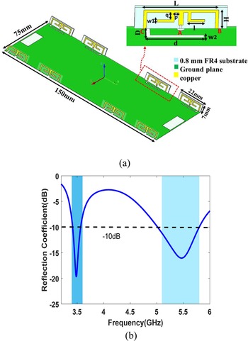
The detailed and physical dimensions of the proposed eight element MIMO array are displayed in Fig. 1(a). The antenna elements are placed symmetrically on the inner surface of the frame of the mobile phone. The mobile phone frames have thickness of 0.8 mm and height of 7 mm that are placed perpendicularly on the PCB board. The size of the substrate is 150 and 75 mm which is a typical size of 5.5-inch smartphone. FR4 substrate (relative permittivity = 4.4, loss tangent = 0.02) is considered as the printed circuit board (PCB) of system and side-edge frame. Each dual-band antenna consists of an L-shaped open slot antenna on the ground and comb-shaped monopole antenna. The monopoles are fed by the 50 Ω microstrip line that is connected by a 50 Ω SMA connector at point A. The monopole is connected to the ground plane at points B and C.
(a) The geometry of the proposed eight elements and (b) the simulated reflection coefficient of single element.

Parametric analysis
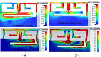
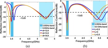
Figure 1(b) shows the simulated reflection coefficient of single element antenna. It is observed that the two desired bands are fully covered under the condition of −10 dB return loss. In this design, the comb-shaped monopole antenna and the L-shaped open slot antenna are used to generate the 5.5 and 3.5 GHz resonant, respectively. To further verify the resonant mode of the two proposed antenna, the simulated surface current and E-field distributions at 3.5 and 5.5 GHz are depicted in Figs 2(a) and 2(b). At 3.5 GHz, as shown in Fig. 2(a) it can be easily seen that strong surface current distributions are mainly concentrated on the closed end of the slot, showing the L-shaped open slot antenna operates at the fundamental quarter-wavelength resonant mode. Hence, the first resonance is determined by the length of L-shaped open slot antenna (d), as shown in Fig. 3(a). It is also seen in Fig. 2(b), that there are two current nulls along monopole, which indicates the first higher order mode at high band. Similarly, for H and L fixed, impedance matching and resonant frequency of high band can be fine-tuned by parameter l, as shown in Fig. 3(b). It is also observed that the two modes can be tuned separately. The optimized parameters of the proposed single antenna are displayed in Table 1.
Simulated surface current and E-field distributions at (a) 3.5 GHz and (b) 5.5 GHz.

Simulated reflection coefficient for different (a) length of slots and (b) length of monopoles.

Optimized parameters of antenna.

Array design
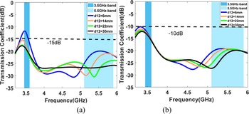
In dual-element antenna array, there are two kinds of arrangement, namely mirrored and shifted configurations that is illustrated in Figs 4(a) and 4(b), respectively. The simulated transmission coefficients of two configurations with different space between them (d12), are shown in Fig. 5. It is observed that in the mirrored case, transmission coefficient S21 is less than −15 and −20 dB in the low band and high band for d12 = 14 mm, while in shifted case, the same S21 value is not achieved even for larger d d12. Therefore, we will use the mirrored configuration for designing eight-element MIMO antenna array.
Two arrangement of dual-element array (a) mirrored and (b) shifted configuration.

Simulated transmission coefficient of two configuration (a) mirrored and (b) shifted.

Eight antenna MIMO array
Array configuration and performances
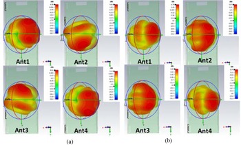
Two different arrangements of 8 × 8 MIMO antenna array are presented namely, cases I and II as illustrated in Fig. 6. In case I, all of the elements are symmetrically located on the two-long edges of smartphone, but in the case II, four elements are located on the two long edges and four other antennas on the top and bottom edges. Based on the result of [Reference Parchin, Al-Yasir, Ali, Elfergani, Noras, Rodriguez and Abd-Alhameed19], the configuration of case I is considered hereafter. The 3D radiation patterns of Ant1-Ant4 at 3.5 and 5.5 GHz are shown in Figs 7(a) and 7(b), respectively. It can be seen that each side of the space has been fully covered.
Two different configurations of eight-elements of MIMO antennas array (a) case I and (b) case II.

Simulated 3D radiation pattern of Ant1–4 at (a) 3.5 GHz and (b) 5.5 GHz.

Thus, the proposed MIMO antenna array presents good radiation coverage which makes it more appropriate to be used in future mobile phones. Also, it can be observed that the maximum radiating orientations of antenna are in different directions, hence, diversity pattern is achieved which, is an advantage for good MIMO performance. Figure 8 depicts the simulated total efficiency. It is seen that, the total efficiencies are better than 60 and 80% in the 3.5 and 5.5 GHz band, respectively.
Simulated total efficiency of Ant1–4.

Measurement and result
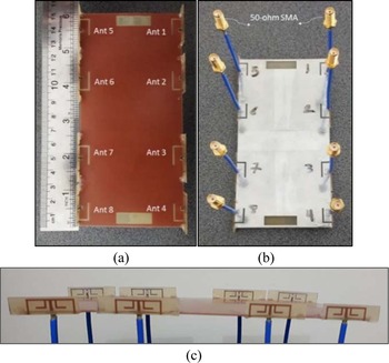
A prototype of the proposed MIMO antenna array was fabricated and tested. Each element was connected to a 50-Ω SMA connector by RF coaxial cable at the corresponding feeding point to the back of system circuit board. It should be noted that, due to the proximity of feeding point to the L-shaped slot and the limitations of fabrication, the clearance width of L-shaped open slot antenna was considered d = 3 mm. The photo of fabricated MIMO antenna array, and its front, side and back view are illustrated in Fig. 9. The measured results were obtained when one antenna element is excited and the other elements, which are not under test, terminated to 50-Ω loads.
Fabricated of the proposed MIMO antenna array (a) top view, (b) bottom view and (c) side view.

S-Parameters
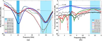
The simulated and measured S parameters are shown in Fig. 10. Due to the symmetrical structure, only the results of the Ant 1–4 are given. It is observed that, the measured S11, S22, S33 and S44 are smaller than −6 dB in the two desired frequency band, and the measured isolations between two adjacent ports (S12, S23, S34, and S24) are better than 11.5 and 15 dB whit in the low band and high band, respectively. Therefore, there are good agreement between the simulated and measured S parameters and the little differences are due to the connector and fabrication losses.
Simulated and measured results of (a) reflection coefficient and (b) transmission coefficient.

Radiation pattern
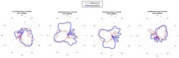
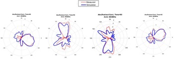
The measured and simulated total realized gain patterns of Ant1–4 in the xoy plane at two different frequency 3.5 and 5.5 GHz are illustrated in Figs 11 and 12, respectively. Although in some direction the measured pattern has not tracked the corresponding simulation result, the overall trend of the two results are similar and the slight difference possibly is due to the test environment errors and other external disturbances. Also, it is observed that Ant1–Ant4 have strong radiation in the φ = 315°, φ = 210°, φ = 180°, and φ = 65°, respectively, in the 3.5 GHz frequency. As shown in Fig. 12, in the 5.5 GHz frequency, maximum radiation is oriented in at the φ = 330°, φ = 90°, φ = 270°, and φ = 30°, respectively. In conclusion, because of difference in the maximum radiating orientations, diversity pattern is achieved which, is an advantage for good MIMO performance.
Simulated and measured total realized gain pattern Ant1–4 at 3.5 GHz.

Simulated and measured total realized gain pattern Ant1–4 at 5.5 GHz.

MIMO performance
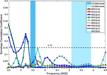
Beside the other radiation performance of antenna, it is important to investigate ECC, mean effective gain (MEG), and channel capacity to evaluate diversity performance of the proposed MIMO antenna. The ECC values are calculated from measured complex radiation far field of antenna by formula explained in [Reference Taga20] and are depicted in Fig. 13. It is observed that the calculated ECC values were smaller than 0.15 which is better than its acceptable threshold.
Simulated ECC values between some adjacent elements.

The MEG of Ant1–4 under propagation conditions Gaussian/uniform (XPR = 5 dB, mv = 10°, mH = 10°, σv = 15°, σH = 15°) [Reference Taga20] were computed directly from CST by the simulated 3D far-field radiation patterns. Then, branch power ratio (k) was calculated for the two antennas by following formula [Reference Sharawi21]:

The calculated MEG and branch power ratio (k) of Ant1–4 are shown in Table 2. It is observed that k is more than −3 dB which is essential to obtain the maximum diversity gain and avoid significant loss in the diversity performance of the MIMO antenna system [Reference Sharawi21].
MEG and branch power ratio (K).

If the transmitter does not know the channel state information (CSI) and the transmit power is equally allocated to every transmit antenna, the ergodic channel capacity can be achieved by the formula given in [Reference Tian, Lau and Ying22]

where I is the identity matrix, SNR denotes the mean SNR, N is the rank of the matrix HH T, H is the channel matrix, and H H denotes the Hermitian transpose of matrix. The channel matrix H is calculated by the Kronecker channel model [Reference Li, Du, Takahashi, Saito and Ito23].
Using this model, the complex channel matrix H can be expressed as

where ΦR and ΦT are the receive and transmit antenna correlation matrix, respectively and {.}1/2 denotes the matrix square root. H w is the white channel matrix that describes the properties of the propagation scenario. When an independent and identically distributed (i.i.d.) Rayleigh fading channel is assumed, the entries of H w are zero-mean circularly symmetric complex Gaussian random variables. It should be noted that the impact of the total efficiency on the antenna correlation matrix is considered here, as explained in [Reference Yun and Vaughan24]

where η r and η t are the receive and transmit diagonal matrices containing the total efficiencies of the receive and transmit antenna elements. By assuming all the antenna elements at transmitter are uncorrelated, i.e., zero-correlation coefficient, the (i, j)th entry of ΨR is calculated by [Reference Kiani, Altaf, Abdullah, Muhammad, Shoaib, Anjum, Damaševičius and Blažauskas25]

where A i(Ω) and $A_j^\;( \Omega )$ represent the field patterns of antenna element i and j, h(Ω) represent incoming wave, { }* denotes conjugate operation, E{ } represents expectation. The mobile wireless environment defined in [Reference Guo, Liu, Liu, Huang and Du26] has a series of reasonable assumptions: the fading envelope being Rayleigh distributed, the incoming wave arriving in horizontal plane only, the incoming wave's orthogonal polarizations being uncorrelated, the individual polarizations being spatially uncorrelated, and finally the time-averaged power density per steradian being constant. Based on these approximations and the derivation in [Reference Yun and Vaughan24], can be written as

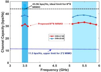
where Γ is the cross-polarization discrimination (XPD) of the incoming wave, that, in this paper is set to 0 dB. As shown in Fig. 14, the channel capacity is achieved by assuming the propagation scenario is independent and identically distributed (i.i.d.) Rayleigh-fading channel. It is observed that, the calculated channel capacity is 32, and 38.7 bps/Hz, for 17 and 20 dB SNR in the receiver, respectively, whereas the ideal 8 × 8 MIMO system by assuming zero correlation and 100% efficiency is about 43.96 bps/Hz.
Calculated channel capacity from measured result.

User's hand effect
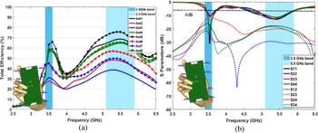
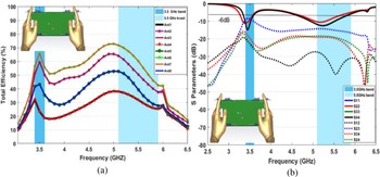
To investigate influence of user's hand and head on the performances of the proposed MIMO antenna, two typical configurations, namely, data mode (single-hand usage, DM), and read mode (two-hand usage, RM) are considered. The simulated S parameters and total efficiency of these modes are shown in Figs 15 and 16. It is observed that for DM scenario shown in Fig. 15(a), the total efficiency of antennas which are close to the phantom hand, i.e., Ant 2, 3, 6, 7 have been reduced more than that of the other elements, which is reasonable, because the hand tissue is a lossy medium and absorbs some part of radiation power. While efficiency of Ant 1, 4, 5, 8 are still higher than 50 and 60% in the low band and high band, respectively. As shown in Fig. 16(a), in RM case, Ant5, 8 are fully covered by fingers hand, hence, the efficiency of these elements has been become 40% lower than that of the free space scenario.
Simulated (a) total efficiency and (b) S-parameters of the proposed MIMO antenna array at data mode usage.

Simulated (a) total efficiency and (b) S-parameters of proposed MIMO antenna array at read mode usage.

Also, Ant1, 4 which are close to the index finger, experience deteriorated efficiency. In this mode, Ant 2, 3, 6, 7 still have efficiency higher than 50 and 60% in the two desired.
Frequency bands. In talk mode configuration, as shown in Fig. 16(a), however, the total efficiencies of all antennas have deteriorated, the efficiency of Ant 2, 3, 6 and 7 are better than 30 and 50% in low band and high band, respectively. The simulated S-parameters of the proposed MIMO antenna array under three scenarios in vicinity of the user's hand are displayed in Figs 15(b) and 16(b). As can be seen; however, the resonant frequency of 3.5 and 5.5 GHz are slightly deviated, the two desired frequency bands are still fully covered under the impedance matching of −6 dB. Also, as can be seen, isolation is not influenced by the hand and head of user.
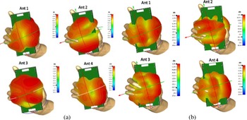
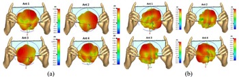
To further investigate the impact of user on the radiation characteristics of the proposed MIMO antenna, the 3D radiation pattern of elements is simulated in the circumstance of data mode and read mode at two frequencies 3.5 and 5.5 GHz, that shown in Figs 17 and 18, respectively. Obviously, it is observed that, the characteristics radiation of the antenna has been influenced by the user's hand; however, it is not working with good radiation coverage and sufficient gain values. In conclusion, the proposed MIMO system is suitable in the practical application and can be considered as a good candidate for 5G smartphone.
Simulated 3D radiation pattern of proposed MIMO antenna array in DM usage at (a) 3.5 GHz and (b) 5.5 GHz.

Simulated 3D radiation pattern of proposed MIMO antenna array in RM usage at (a) 3.5 GHz and (b) 5.5 GHz.

Table 3 shows the performance comparison between the proposed antenna array and those that have been reported. It is observed that, the proposed eight-element array has higher isolation (>10 and >15 dB in the LB and HB, respectively) with a lesser loss in total efficiency (>60 and >80% in the LB and HB, respectively), which, in [Reference Guo, Cui, Li and Sun14] and [Reference Zou, Li, Sim and Yang15], this feature have not been achieved. In addition, multi-band operation antenna which is important in the mobile phone communication, has not been implemented in [Reference Jiang, Liu, Cui and Hu5, Reference Anping Zhao16–Reference Jiang, Liu, Cui and Hu18]. Therefore, it can be concluded that, the proposed antenna array can support dual-band operation with high total efficiency and isolation, which is a unique feature that all the references do not have.
Comparison between the proposed antenna array and the referenced 5G antennas.

a Only 8 × 8 MIMO array are considered for comparison.
Abbreviations: NL, neutralization line; GS, ground slot; NG, not give.
Conclusion
In this paper, a dual-band eight-elements MIMO antenna array for 5G future mobile phone operating in the 3.5 GHz (3.4–3.6 GHz) and 5.5 GHz (5150–5925 GHz) for 5G future mobile phone has been presented, fabricated and measured. In particular, the antenna elements include a comb-shaped monopole antenna and L-shaped open slot antenna that are located on the frame of handset. Two desired frequencies bands have been fully covered under the impedance matching of −6 dB and high isolation better than 11.5 and 15 dB has been achieved without any decoupling structure. The simulated total efficiency is better than 60 and 80% in the low band and high band, respectively. Due to proper placement of the antenna elements, pattern diversity has been achieved which improves the ECC between antenna elements (ECC < 0.1). Furthermore, the calculated channel capacity by considering impact of the total efficiency is 38.7 bps/Hz (SNR = 20 dB). The performances of proposed antenna in vicinity of user's hand have also been investigated and the results indicated that the proposed MIMO antenna can be considered as a good candidate for 5G smartphone.
 Mahsa Zabetiakmal obtained the B.Sc. and M.Sc. both in electrical communications from the Department of Electrical Engineering at Amirkabir University of Technology (Tehran Polytechnic), Tehran, Iran in 2017 and 2019, respectively. She is currently a Ph.D. student in Amirkabir University of Technology. Her research fields are planar structure, antennas, and 5G systems.
 Gholamreza Moradi (M’09–SM’16) obtained the Ph.D. degree in electrical engineering from Amirkabir University of Technology (Tehran Polytechnic), Tehran, Iran in 2002. He is currently an associate professor in the Electrical Engineering Department, Amirkabir University of Technology, and director of microwave measurement research lab. From June 2016 to February 2017, he was a visiting professor with the University of Alberta. He has published and presented over 100 papers in the refereed journals and international conferences. His main research interests are numerical electromagnetics, antennas, active microwave and mm-wave circuits and systems.
 Ayaz Ghorbani obtained the postgraduate diploma, M.Phil., and Ph.D. degrees in electrical and communication engineering and the Ph.D. degree from the University of Bradford, Bradford, UK, in 1984, 1985, 1987, and 2004, respectively. Since 1987, he has been teaching various courses with the Department of Electrical Engineering, Amirkabir University of Technology, Tehran, Iran. He has authored or co-authored more than 100 papers in various conferences as well as journals. Dr. Ghorbani obtained the John Robertshaw Travel Award and the URSI Young Scientists Award from the General Assembly of URSI, Prague, Czech Republic, in 1990. He was a recipient of the Seventh and Tenth Khwarazmi International Festival Prizes, in 1993 and 1995, respectively, for design and implementation of an anti-echo chamber and microwave subsystems.