I. INTRODUCTION
Biogenic ceramic materials such as nacre feature both remarkable strength and toughness exceeding that of their pure inorganic constituents. Reference Wegst, Bai, Saiz, Tomsia and Ritchie1 It is the delicate structural organization across multiple levels of hierarchy which affords biominerals such mechanical properties on the macroscale and renders them an unfathomable source of inspiration for material design. Each level of hierarchy contributes to the macroscale properties and may add a specific key feature on its own characteristic length scale. For instance, biominerals often feature nanogranular organization which adds nanoplasticity to the mineral body thereby toughening it and rendering it insensitive to nanoscaled flaws. Reference Wolf, Böhm, Harris, Hajir, Mondeshki and Marin2–Reference Huang and Li7 A thorough understanding of such hierarchical systems cannot be accomplished simply by a deconstructive approach as emergent properties may contribute significantly to those on the macroscale. Since it is not possible to generate perfect biomimetic analogues of a highly sophisticated hierarchical composite material such as a mollusk shell, a comparative approach contrasting different species could give valuable insights into structure–property relationships, the influence of individual structural motifs, and the self-organization processes by which the formation of the structural motifs are governed.
The sophistication of the shell's organization from the macro- to the nanoscale is owed to an evolutionary pressure imposed by external threats such as predators or tidal impacts. This has led to the generation of exceptionally tough composite materials increasing the survival rate of the respective organism. Reference Barthelat, Li, Comi and Espinosa8,Reference Checa, Cartwright and Willinger9 Nature has tackled this problem by generating protective and nonbrittle ceramics from abundant resources at low temperature. It is quite remarkable that this invention was not a singular event during evolution but occurred in multiple instances during the course of time: each of the different mollusk shell microstructures, e.g., prisms, nacre, or crossed-lamellae, represent one evolutionary (sufficiently) successful solution for this demanding challenge. Moreover, there has been reasonable speculation that the delicate but fundamental structural deviations between columnar nacre, commonly observed in gastropods, and sheet nacre, commonly observed in bivalves, actually indicate that mother-of-pearl has been independently created by nature twice. Indeed, Jackson et al. were recently able to corroborate this assumption by evidencing that the secretion profile of the calcifying epithelial mantle cells which form nacre in Pinctada maxima (bivalve) and in Haliotis asinine (gastropod) differ fundamentally. This clearly advocates parallel and independent development of nacre in gastropods and bivalves. Reference Cartwright and Checa10
Besides nacre—the most intensively studied mollusk shell structure—other non-nacreous shell microstructures such as homogeneous, foliated, prismatic, crossed-lamellar, and complex crossed-lamellar may hold new inspiration for material design and synthesis. Reference Currey and Taylor11 The observation of Jackson et al. demonstrates simply that we should expect structural deviations in all microstructures across the species. Reference Cartwright and Checa10 Moreover, Cartwright et al. showed that in the case of nacre, Reference Cartwright and Checa10 such structural deviations may grant further insight into the formation of biominerals and their inherent toughening mechanisms. Reference Wegst, Bai, Saiz, Tomsia and Ritchie1,Reference Burghard, Zini, Srot, Bellina, Van Aken and Bill12 Of the five nonnacreous microstructures, the crossed-lamellar microstructure is the most common, and features the highest fracture toughness of all mollusk shell microstructures. Reference Kamat, Su, Ballarini and Heuer13 The shell of the Queen Conch Strombus gigas, a gastropod, is a pertinent example of the crossed-lamellar microstructure in which four different levels of organization have been identified. Reference Kamat, Su, Ballarini and Heuer13,Reference Kuhn-Spearing, Kessler, Chateau, Ballarini, Heuer and Spearing14 The so-called “third order lamellae” represent one of the lowest orders of organization, and are made from lath-like single or twinned crystals of aragonite separated by a fine organic layer, these are combined into polycrystalline bundles, dubbed the “second order lamellae”, which, in turn, are stacked to give the “first order lamellae”, which are ensheathed by an organic chitinous layer. Reference Kuhn-Spearing, Kessler, Chateau, Ballarini, Heuer and Spearing14,Reference Pokroy and Zolotoyabko15 The characteristic plywood-like structure is then generated by alternate tilting of the adjacent first order lamellae. Reference Kamat, Su, Ballarini and Heuer13,Reference Kuhn-Spearing, Kessler, Chateau, Ballarini, Heuer and Spearing14,Reference Weiner, Addadi and Wagner16–Reference Yang, Zhang, Liu and Li18 The shell is subdivided into three macroscopic layers, the outer, the middle, and the inner layer, which are arranged so that the first order lamellae are oriented in an approximately 0°/90°/0° arrangement giving the final hierarchical layer of the Queen Conch shell S. gigas. Reference Kuhn-Spearing, Kessler, Chateau, Ballarini, Heuer and Spearing14 Although the crossed-lamellar shell microstructure features the highest fracture toughness with respect to all nonnacreous shell microstructures, Reference Kuhn-Spearing, Kessler, Chateau, Ballarini, Heuer and Spearing14 only little is known about its formation mechanisms and the essential structural design motifs occurring across the species.
In this contribution, we explore the hierarchical organization of the dog cockle Glycymeris glycymeris (Linné 1758), a relatively mundane bivalve belonging to the order of Arcoida, to identify structural deviations in the hierarchical organization of crossed-lamellar shells. By detailed comparison with the pertinent literature discussing the microstructural features of other crossed-lamellar mollusk shells, we reveal significant structural similarities and deviations across the species. Additionally, we point out that certain structural features can be related to infradian Zeitgeber (i.e., external triggers) to which the mollusk is exposed. We further discuss the contributions of the hierarchical structural elements to the macroscopic mechanical properties. Our findings encourage an exhaustive comparison of crossed-lamellar shells to identify as yet unknown key structural elements in these complex biominerals and to further understanding of the intrinsic self-organization and toughening mechanisms.
II. RESULTS AND DISCUSSION
A. The layered organization of the palliostracum of G. glycymeris and its subdivision into first order lamellae
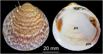
The bivalve shell Glycymeris glycymeris is endemic in various oceans, and is especially prevalent in the shallow waters of intertidal zones. Reference Oliver and Holmes19 This report is focused on the palliostracum of G. glycymeris, which is the section of the shell that is formed by mantle tissue cells (ps in Fig. 1). It consists of several mineral layers, i.e., the ectostracum (outer mineral layer), the mesostracum (middle layer, if present) and the endostracum (inner layer), and is protected from the seawater by the periostracum, an organic coating which also serves as a substrate for the first mineralization event. Reference Oberling20
Shell of the bivalve Glycymeris glycymeris (Linné 1758). Annual growth lines are exemplified by white arrows. The myostraca, i.e., the adductor myostracum (am) and the pallial myostracum (pm), consist of prismatic calcite and are formed by muscle cells whereas the palliostracum (ps) is made from crossed and complex-crossed aragonite lamellae and is formed by mantle cells.

The palliostracum of G. glycymeris typically exhibits prominent growth lines which run in a commarginal direction parallel to the shell margin and perpendicular to the direction of growth. For the reader's convenience, we provide, in the supporting information, a short overview of the geometric terminology of bivalve shells used in this article, see Fig. S1. Seven very prominent macroscopic growth lines similar to those indicated by arrows in Fig. 1 were observed in a selected shell of dimensions 45 mm × 47 mm. Growth lines are known to arise due to dramatic changes in environmental parameters, such as a seasonal drop in temperature causing reduced shell growth. Reference Dame21 Therefore, these annual growth lines allow for assessment of the age of the specimen as they simply record a circannular rhythm of the organism. Noting that no growth line is formed in the first year, we estimated an age of 8 years of our exemplifying specimen, which is in good agreement with the age obtained from the assessment of the radial height from the umbo to the ventral margin of the valve as used previously. Reference Morvan22
The palliostracum of G. glycymeris, i.e., the central part of the shell bounded by the myostracal line (Fig. S1), is predominantly composed of aragonite as demonstrated by X-ray diffraction (XRD) phase analyses and contains a minor organic fraction according to thermogravimetric analysis (TGA; less than 1.5 wt%, see Fig. S2). Reference Taylor, Kennedy and Hall23 The myostraca consist of prismatic calcite probably because this provides better attachment of the adductor muscle to the muscle scar and of the mantle to the ventral margin (Fig. 1). In this contribution we will focus on the hierarchical structure of the palliostracum of G. glycymeris.
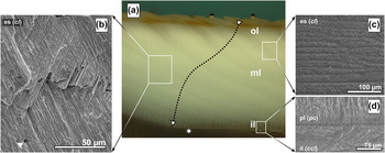
A cross-section of the palliostracum reveals a sequence of three layers, the outer layer and thus oldest layer [ol in Fig. 2(a)], the middle layer [ml in Fig. 2(a)], and the inner layer [il in Fig. 2(a)]. The inner layer (also called endostracum), which is separated by a thin calcitic pallial line [pl in Fig. 2(b)] from the middle layer, is the only layer which is built from complex-crossed lamellae [ccl in Fig. 2(d)]. The outer and the middle layers, consist of aragonitic crossed-lamellae [cl in Figs. 2(b) and 2(c)] which have a typical thickness of 5–7 µm in the outer layer near the periostracum increasing to 8–9 µm toward the middle layer. The lamellae run continuously through the outer layer and the middle layer, as indicated by the dotted arrow in Fig. 2. In the outer layer, the pathway of the lamellae is curved, which straightens as the lamellae enter the middle layer. In the middle layer, the lamellae thickness increases steadily from 8–9 µm close to the outer layer to a typical thickness of 13–17 µm near the pallial line [Fig. 2(a)]. As the lamellae are continuous with only their orientation altering at the apparent boundary between the outer and the middle layer (i.e., no structural interruption) and no delamination was observed in fracture experiments, we propose that the outer and the middle layer should be considered as one ectostracum [es in Fig. 2(a)] in which only the orientation of the lamellae changes.
Palliostracum of G. glycymeris. (a) A radial section through the shell depicts the ectostracum (es) with its apparent subdivision into outer layer (ol) and middle layer (ml). The star at the pallial line designates the first appearance of the inner layer (il). The arrow indicates the bent trajectory of the growth lines through the ectostracum. An increasing thickness of the lamellae from the outer layer toward the inner layer is observed and depicted in Scheme 1. (b, c) The ectostracum features a crossed-lamellar (cl) microstructure; its lath-like aragonite plates can be visualized either by cracking (b, commarginal fracture surface) or polishing and subsequent etching (c, commarginal section). The triangle (in b) denotes one of the microtubuli which penetrate the palliostracum. (d) (radial section) The inner layer (il) consists of complex-crossed lamellae (ccl) which are separated from the ectostracum by the pallial line (pl) made from prismatic calcite (pc).

The reorientation of the lamellae across the ectostracum bears a remarkable similarity to the 0°/90°/0° arrangement of the laminated organization observed in the Queen Conch S. gigas albeit within a single layer. In S. gigas, the laminated assembly in conjunction with the inherent reorientation of the lamellae is assumed to have a distinct impact on its macroscopic mechanical properties: due to the orientation of the lamellae in the outer layer, multiple channel cracks are initiated which then are temporally arrested at the outer/middle layer interface. Due to the orientation of the lamellae, the cracks are deflected and delocalized considerably increasing the crack path length. Reference Kuhn-Spearing, Kessler, Chateau, Ballarini, Heuer and Spearing14
We thus hypothesize that the peculiar bending of the lamellae orientation follows a comparable design principle to that which underlies the laminated setup in S. gigas: in the case of crack formation, the energy is dissipated in multiple channel cracks rather than one large crack because the lamellae are oriented nearly parallel to the surface normal (see Scheme 1). The crack follows a path given by the interlaminar organic matrix which is less crack-resistant. Due to the bent trajectory, the crack is deflected and crack energy is dissipated, and delamination as seen in S. gigas is not observed. As mentioned above, the width of the lamellae increases as they traverse the ectostracum thereby providing an additional means to distribute the crack energy in a larger volume. At the boundary of the ectostractum/palisade layer, the orientation of the lamellae is nearly perpendicular to the inner shell surface. We assume that the toughening effect of the palisade layer is not as important as that of the complex-crossed layer: as soon as the crack reaches the inner complex-crossed lamellar layer, crack growth is strongly impeded by multiple small cracks generating a distributary network of crack channels similar to the complex crack channeling by enamel rods observed in teeth. Reference Yahyazadehfar, Bajaj and Arola24
Schematic Organization of the palliostracum. The scheme depicts the bent growth trajectory of the lamellae in the outer layer, which then straightens as the lamellae reach the middle layer (dotted arrow). The lamellae concurrently increase in thickness with straightening of the growth trajectory. The italic abbreviations give the respective microstructure of the layer: cl—crossed lamellae, pc—prismatic calcite, ccl—complex-crossed lamellae.

Assuming that the growth of lamella is initiated per day in the outer mantle fold at the ventral tip of G. glycymeris, the average lamella thickness of 16 µm in the middle layer can be interpreted as a daily growth rate of the bivalve shell. Given an approximate shell length of 45 mm, the age of the shell could roughly be estimated to be 7.71 years (in solar days, with 365 solar-days per year) and 7.97 years (calculated with 353 lunar days per year) which is in good agreement with the age of eight years estimated by the annual growth lines and confirms our assumption of the observed lamellae being daily growth lines. In contrast Cuif et al. recently stated that these “coherent microstructural layers forming the cross-lamellar structure are not growth layers”. Reference Cuif, Dauphin and Sorauf25 Whereas, Clark proposed earlier that these lamellae are in fact daily growth lines which might be deposited solar-daily (24.00 h) or lunar-daily (24.84 h). Reference Clark26 Our findings support the claim of Clark et al. that the first order lamellae are formed in a circadian rhythm, be it in solar or lunar days. It is more reasonable to assume lunar days as these are reflected in the tides which cause the opening and closing of the valves. Intertidal species such as G. glycymeris are only able to mineralize their shells during high tides when their valves are opened and they can access their only calcium source, the open sea. Reference Rhoads, Lutz, Rhoads and Lutz27 In other words, the layer-wise organization of the first order lamellae is a result of an external trigger based on a circatidal rhythm. This clearly demonstrates the importance of maintaining a holistic view on the biomineralization system in question and the requirement for observation of internal and external parameters as the genesis of the microstructure is governed not only by internal parameters or self-organization processes but also by external Zeitgeber stimuli such as circatidal or circannular rythms.
B. Macroscopic assessment of the mechanical properties of the growth lamellae
Due to the anisotropic organization of the growth lamellae, we expected that the radial fracture behavior along the dorsal–ventral axis will differ significantly from a commarginal fracture, i.e., along the growth lines (Fig. S1). We therefore assessed the maximum work of fracture in both directions by flexural tests using a three-point bending mode setup. The fracture was generated in such a way that it propagated from the outer to the inner layer of the shell, as would occur naturally e.g., from the attack of a predator. The samples with the fracture oriented along the radial axis showed a higher maximum work of fracture (W f,rad = 78.98 ± 15.06 J/m2) than samples with commarginal fracture perpendicular to the radial direction (W f,com = 20.29 ± 3.84 J/m2).
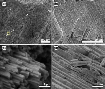
Comparing the maximum work of fracture of the shells with the work of fracture of pure geological aragonite Reference Jackson, Vincent and Turner28 reveals that the work of fracture of G. glycymeris shells is, in both directions, approximately two orders of magnitude higher than that of pure aragonite. We postulate that the reason for the increased work of fracture is mainly caused by the increased path of the crack through the crossed-lamellar structure compared to the straight crack path in pure aragonite paired with pull-out effects due to the laminar microstructure [Figs. 3(a) and 3(c)]. Reference Kuhn-Spearing, Kessler, Chateau, Ballarini, Heuer and Spearing14 Investigations of the fracture surfaces in both directions (Fig. 3) corroborated this assumption and further revealed why the work of radial fracture is distinctly larger than the work of commarginal fracture. A commarginal crack can propagate along the interlamellar interface, observed as relatively smooth surfaces within the fracture surface [Fig. 3(b)]. The fracture surface along the radial axis is in stark contrast to this: here, the propagating crack had to be reinitiated at every single growth line [Fig. 3(a)]. This anisotropic organization assures that the reinforcement of the shell is superior in the radial direction and cracks will propagate preferentially in a commarginal direction. This is an important consideration with regards to protection of the organism from severe shell failures: small parts of the bivalve shell chip preferentially in a commarginal direction which is less fatal or lethal than radial cracking of the shell.
Fracture surfaces of the crossed-lamellar ectostracum of G. glycymeris. (a) Radial fracture surface i.e., perpendicular to the growth lines, showing a relatively rough surface as the crack had to be reinitiated at every growth line. The area marked by a yellow box is presented in a higher magnification in Fig. 5(d). (b) Commarginal fracture surface, i.e., parallel to the growth lines, showing a relatively smooth surface as the crack could propagate along the interlamellar interface. (c) High resolution image of a bundle of third order lamellae and their surface roughness at the submicrometer scale. (d) High resolution micrograph reveals surface roughness of the individual third order lamellae and their preferred cleavage orthonormal to the axis of the third order lamellae.

C. The structural features of the third order lamellae and the absence of second order lamellae
Based on observations made in various species, Reference Kamat, Su, Ballarini and Heuer13,Reference Kuhn-Spearing, Kessler, Chateau, Ballarini, Heuer and Spearing14,Reference Weiner, Addadi and Wagner16–Reference Yang, Zhang, Liu and Li18 the organization of the crossed-lamellar microstructure is as follows: first order lamellae are stacks of second order lamellae which consist, in turn, of bundles of third order lamellae. In G. glycymeris the third order lamellae were readily observed by polarized light microscopy and scanning electron microscopy (SEM) [Figs. 2(a)–2(c)] whereas no second order lamellae could be detected. Scanning electron micrographs of freshly cleaved fracture surfaces clearly show the individual third order lamellae [Fig. 3(c)]. They have a typical cross-section of approximately 100 × 100 nm2 to 200 × 200 nm2 and reveal a distinct surface roughness on the scale of a 10th of a micron. This surface roughness is well documented in Fig. 3(d). This substructure, along with its preferred cleavage orthonormal to the third order lamella's long axis, might correspond to the fourth order nanoblocks discussed by Younis et al. for the crossed-lamellar gastropod Murex troscheli. Reference Younis, Kauffmann, Pokroy and Zolotoyabko29 In nacre, a similar surface roughness of nacre platelets causes progressive locking and hardening by spreading of nonlinear deformation around cracks or defects. Reference Barthelat, Rim, Espinosa, Bhushan and Fuchs30 Despite our adherence to procedures by which the second order lamellae in other species were located, e.g. in the gastropod Saxidomus purpuratus Reference Yang, Zhang, Liu and Li18 and the gastropod Murex troscheli Reference Younis, Kauffmann, Pokroy and Zolotoyabko29 no second order lamellae were found. The third order lamellae of G. glycymeris seemed to be unsystematically stacked on top of each other, omitting the organization into second order lamellae [Fig. 3(c)].
D. Nanoscopic organization of the crossed-lamellar ectostracum
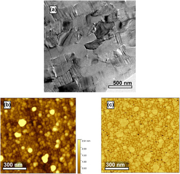
To gain more information about the nanoscale structure of the individual third order lamellae, ion-thinned wedge samples were investigated by transmission electron microscopy (TEM) and they revealed a banded internal structure of the third order lamellae with a spacing between 1 and 20 nm [Fig. 4(a)]. These structures arise from twinning within the aragonite third order lamellae, an observation already reported in other species such as G. yessoensis. Reference Kobayashi and Akai31 Twins can originate due to three different causes, i.e., growth twinning, transformation twinning, and twinning due to mechanical stress. Due to the sample preparation used, the latter two causes can be excluded, we therefore hypothesize that the twinning of the third order lamellae occurs due to anomalies during shell growth, like those found in G. yessoensis or S. gigas. Reference Kamat, Su, Ballarini and Heuer13,Reference Kobayashi and Akai31
Structural features of G. glycymeris on the nanoscale. (a) Transmission electron micrograph visualizing the individual third order lamellae and their internal twinning. (b and c) Atomic force micrographs in tapping mode of a commarginal mirror-polished section showing individual nanogranules which form a space-filling mineral body. Subfigure (b) contains the height information, subfigure (c) is the phase image of the same region depicted in (b).

Atomic force micrographs, obtained in tapping mode both from freshly polished or freshly fractured samples, revealed the fifth and fundamental level of organization. The lamellae of G. glycymeris are composed of individual nanogranules which form a densely packed and space-filling mineral body [Fig. 4(b)]. The phase image of the investigated area indicates that the granules might be enwrapped by a softer material, i.e., a proteinaceous or organic moiety which is entrapped in the biomineral [Fig. 4(c)]. It is a generally accepted model that nanogranular organization is due to a particle-mediated growth mode of the shell Reference Wolf, Böhm, Harris, Demmert, Jacob, Mondeshki, Ruiz-Agudo and Navarro32 : the epithelial cells probably enrich amorphous calcium carbonate in vesicles, which one may call calcosomes, Reference Wolf, Lieberwirth, Natalio, Bardeau, Delorme, Emmerling, Barrea, Kappl and Marin33 which they then release into the extrapallial space. The biomineral is then constructed by a particle-accretion mechanism involving a quasisolid state transformation aided by water. Reference Gal, Kahil, Vidavsky, DeVol, Gilbert, Fratzl, Weiner and Addadi34–Reference Hovden, Wolf, Holtz, Marin, Muller and Estroff38 The nanogranules, which can also be found in various other biominerals, Reference Wolf, Böhm, Harris, Hajir, Mondeshki and Marin2,Reference Wolf, Böhm, Harris, Demmert, Jacob, Mondeshki, Ruiz-Agudo and Navarro32,Reference Dauphin39–Reference Sethmann, Hinrichs, Wörheide and Putnis41 may render the biomineral nanoplastic on small scales and additionally toughen the biomineral by adding two new energy dissipation modes on the nanoscale, i.e., nanograin rotation and nanograin deformation. Reference Tai, Ulm and Ortiz3–Reference Gao, Ji, Jager, Arzt and Fratzl5
E. Microtubuli
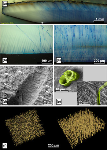
The shell of G. glycymeris features an exceptional characteristic: microtubules perpendicularly penetrate the palliostracum from the inner side (Fig. 5). Reference Oberling20 The tubuli were 3–5 µm in diameter and ran straight and without interruption through the shell, as demonstrated by a microtomographical reconstruction [Fig. 5(f)]. Blue staining applied on the outer layer penetrates the whole shell thickness and is visible after a short period of time on the inner shell surface [Figs. 5(a)–5(c)] which further corroborates that the channels traverse the whole shell. The mutual orientation of the microtubules is documented by polarized light microscopy which allows identification not only of microtubules at the sample's surface but also of those located just beneath the sample surface. Furthermore, the staining experiments [Figs. 5(a)–5(c)] revealed that these tubules are not yet present at the ventral margin of the palliostracum. This clearly demonstrates that these channels are not primary tubuli formed during shell growth but are formed posthoc by the mantle cells by etching channels into the palliostracum and are therefore so-called secondary tubuli. Reference Araujo, Ramos and Bedoya42 Scanning electron micrographs of freshly cleaved shell fragments revealed round-edged third order lamellae within the microtubule surface compared to the sharp-edged third order lamellae next to the microtubules [Fig. 5(d)] corroborating the assumption that the tubuli are formed by an etching process. Etching of cross-sections of the palliostracum for 2 min with a 1% ethylenediaminetetraacetic acid (EDTA) solution dissolved the mineral phase and resulted in small cylinders of organic material protruding from the tubuli [Fig. 5(e)]. The location and morphology of the organic material indicate they result from an organic layer which coated the inside of the tubuli of the overlying layer which was removed during etching.
Microtubuli penetrate the palliostracum of G. glycymeris. (a) Microtubuli revealed by a penetrating dye; the star marks the first occurrence of the inner layer and evidences that the inner layer and the microtubules start to appear at the same location. (b, c) Higher magnification optical micrographs of the ecto- and endostracum which document that the tubule density increases with the distance to the shell margin. (d) Detailed view of the fractograph depicted in Fig. 3(a) showing a fracture surface revealing a microtubule. The direction of crack propagation is indicated by arrows. The third order lamellae of the microtubule surface are round-edged compared to the sharp-edged third order lamellae exposed by the crack. (e) Etching of the polished microsection dissolved the overlying mineral phase, the organic coating of the microtubule surface remain which protrudes from the surface [(upper left) transversal section, (lower right) commarginal section]. False colors were applied as a guide to the eye accentuating the organic coating of the tubules; a noncolorized micrograph is provided in the Supplementary information (Fig. S3). (f) Microtomography of the palliostracum evidencing the parallel orientation of the microtubules.

Interestingly, the formation of the tubuli clearly coincides with the deposition of the inner layer [Figs. 5(a)–5(b)] and microtubule density increases toward the dorsal end of the shell [up to 300 tubules per mm, see Fig. 5(c)]. It is thus reasonable to hypothesize that a certain type of specifically differentiated mantle cells are responsible for generation of these channels and that these cells are either colocalized or identical with the class of epithelial cells depositing the inner layer. The function of the microtubuli remains unclear; it is speculated that they serve for fixation of the mantle to the palliostracum or that they take part in a sensoring system by transmission of light through the shell. Reference Araujo, Ramos and Bedoya42 We believe that this structural feature also has a distinct impact on the mechanical properties of the shell as it may serve as a simple crack arrestor necessitating crack reinitiation for further propagation of an arrested crack [as indicated by arrows in Fig. 3(a)]. This crack stopping effect might even be enhanced by an organic coating which covers the interior surface of the microtubuli.
III. CONCLUSIONS
We have characterized the hierarchical organization of the palliostracum of the intertidal bivalve shell Glycymeris glycymeris (Linné 1758) and identified at least five different levels of structural organization. On the coarsest level, we found two macroscopic layers: the ectostracum and the inner layer (endostracum). The ectostracum represents the main part of the shell, notably, the orientation of the growth lamellae in this area follows a bent trajectory on the microscale. This is in remarkable similarity to the three-layered design of the Queen Conch shell S. gigas and, therefore, the ectostracum of G. glycymeris may have a similar impact on crack propagation, crack deflection, and energy dissipation mechanisms like the laminate design of S. gigas. In G. glycymeris, this design feature is realized within one shell layer, the ectostracum, which is superior as it circumvents delamination which is typically observed in the S. gigas shell.
The ectostracum belongs to the class of crossed-lamellar microstructures, i.e., a plywood-like structure generated by mutually tilted bundles of third order lamellae which measure several micrometers in length and have a cross-section of 100 × 100 nm2 to 200 × 200 nm2. The third order lamellae show significant internal twinning and a distinct surface roughness on the submicron scale. This roughness might add to the macroscale mechanical properties in a similar way as observed in nacre. Organization of the third order lamellae into second order lamellae, as seen in other species such as S. gigas, was observed. The fundamental underlying level of hierarchical organization was revealed by atomic force microscopy (AFM) analysis which demonstrated that the individual third order lamellae are composed of densely packed nanogranules which form a space-filling mineral body into which organic molecules are probably incorporated. This nanogranular organization further toughens the biomineral by adding nanoplasticity. It additionally extends the crack path and provides energy dissipation mechanisms such as grain rotation and deformation. Reference Tai, Ulm and Ortiz3,Reference Li, Xu and Wang4
We further evidenced and characterized a specific structural feature in the shell of G. glycymeris. As soon as the inner layer is deposited, the shell is penetrated by secondary (i.e., posthoc formed) microtubules which run from the interior to the external shell surface. The purpose of these tubuli is yet unclear but fracture surfaces showed that they probably act as crack arrestors.
The absence of the second order lamellae in G. glycymeris shows that the nomenclature which has so far been used to describe crossed-lamellar structures has been unfortunately chosen; as a consecutive order of structural elements collapses as soon as one element is missing. This may lead to misconception when comparing the microstructure of different species. We therefore advocate a new nomenclature: lamellae (i.e., first order lamellae), sublamellae (i.e., second order lamellae) and needles (third order lamellae).
In summation, we have identified five different levels of hierarchical organization in the palliostracum of the bivalve G. glycymeris. On the macroscopic level, we find the endo- and the ectrostracum. On the mesoscale, we identified two different structural motifs, the microtubules which penetrate the shell and the bent trajectories of the lamellae in the ectostracum. On the microscale, we found lath-like growth lamellae which are, on the submicroscale, composed of individual aragonite needles. On the lowest level, we found, in addition to twinning in the needles, a granular composition on the nanoscale.
The organization of the crossed-lamellar microstructure and its connection to external circatidal and circaanular stimuli exemplify clearly that it is imperative to take external triggers outside the biological system into account to fully understand the morphosynthesis of such complex mineralizing systems. Endogeneous rhythms, which are triggered by external Zeitgeber, contribute and (co-)control at least two structural elements in the hierarchical structure of G. glycymeris. This demonstrates that, for a complete understanding of the self-organization processes in biomineralizing systems, it is insufficient to rely fully on a reductionistic approach. A holistic view on the organisms including external triggers emanating from the habitat is mandatory for complete understanding of the formation and self-organization of such microstructural composite materials.
IV. EXPERIMENTAL DETAILS
Specimens of Glycymeris glycymeris were obtained from local vendors in France who harvested them in the Breton intertidal. Different sections of various orientations were prepared with a disc cutter (WOCO 50 P, UniPrec, Clausthal-Zellerfeld, Germany), equipped with a diamond cutting wheel (WOCO 90/7, UniPrec). For polishing, the sections were embedded in Specifix-20 (Struers, Willich, Germany) and then flattened with a series of SiC grinding papers with (p80 to p4000, Struers). Polishing was finalized by diamond lapping films with a 3 µm grain size (Allied, Rancho Dominguez, California). Controlled etching of the surface was achieved with a 1% EDTA solution. Fracture surfaces, both parallel and tangential to the growth direction, were generated manually with a set of pliers; to generate a fracture surface in direction of shell growth, predetermined breaking points were applied.
Fracture surfaces as well as polished and etched sections were investigated with a polarized light microscope (BX51, Olympus, Hamburg, Germany) and scanning electron microscopy (SEM; Quanta200, FEI Company, Hillsboro, Oregon).
For transmission electron microscopy (TEM) investigations, ion-thinned wedge samples were prepared from mechanically prethinned specimens. Prethinning was achieved by mechanical lapping (Allied MultiPrep) with a waning series of micronsized diamonds embedded polishing films (from 6 to 0.01 μm) of initially 500 µm thick samples, extracted from the shell with a diamond wire saw (Model 3242, Well, Mannheim, Germany). Etching was suppressed by using a nonwater based lubricant (Blue lube, Allied). For the first side polish, samples were attached to aluminum-polishing stubs (Allied) with Crystal Bond (Allied). For the second side, the sample was glued face-down onto a Pyrex polishing-stub (Allied) with a very thin layer of super glue (Loctite, Westlake, OH) and the polishing procedure was repeated at a 3° pitch. To obtain electron-transparent samples, the polished wedges were ion-thinned at 8 °C for 12 h at 2 kV, followed by a 4 h thinning with 1 kV (MODEL 695, Gatan, Pleasanton, California). TEM investigations were conducted with a CM 300 UT High-Resolution Transmission Electron Microscope (Philips, Amsterdam, The Netherlands) operated at 300 kV acceleration voltage which was equipped with a slow scan charge coupled device camera (TVIPS, Gauting, Germany).
For AFM, the shell was cut into small pieces with a low speed diamond saw and then mirror-polished as described previously. After completion, samples were cleaned with acetone, dried in air—no additional etching was performed. All AFM images were recorded with a Dimension 3100 CL in tapping mode employing Al-coated silicon cantilevers (Olympus, OMCL-AC160TS-W2, r < 10 nm). Image processing and analysis were performed with the open-source software Gwyddion v2.25, see http://gwyddion.net/.
To visualize the locus and penetration behavior of the microtubules, an approach similar to that of Hallett et al. Reference Hallett, Dexter and Seville43 was used. Instead of methylene blue, simply a blue permanent marker (Edding, Ahrensburg, Germany) was used. X-ray microtomography (µ-CT) was used to visualize the three-dimensional distribution of microtubuli in the bivalve shell. Samples with a diameter of 1.42 mm were prepared with a drilling machine (561/02 series, Herbert Arnold GmbH & Co. KG, Weilburg, Germany). The µCT scan was performed with a Skyscan 1172 (Bruker, Billerica, Massachusetts) equipped with an aluminum filter of 0.5 mm and a C93000 CCD detector (Hamamatsu Photonics K.K., Hamamatsu City, Japan) featuring 11 megapixel at a pixel size of 8.93 µm. The measurements were performed at 100 µA source current and 80 kV source voltage. For visualization, the software package Amira 3D Software for Life Sciences (FEI) was used.
The maximum work of fracture in the direction of growth, i.e., perpendicular to the main orientation of the lamellae, and perpendicular to the direction of growth, i.e., parallel to the lamellae, was estimated by flexural tests in the three-point bending mode with an universal testing machine (Instron 5565, Instron, Norwood, Ohio) at a test velocity of 0.5 mm/min and with the help of a 500 N load cell. As the sample dimensions, according to neither DIN EN 843-1 [2] nor ASTM E 1820-08, could be fulfilled (due to the limited thickness and the curvature of the shell), neither the work of fracture nor the fracture toughness could be reliably determined. Therefore, we give instead the maximum work of fracture. Ten samples with fracture in direction of growth and ten samples with fracture perpendicular to the direction of growth were prepared from four individual bivalve shells by the aid of a diamond band saw (BS230 XY, Dramet, Kleinmaischeid, Germany), equipped with a 0.25 mm thick diamond band with diamond size D76 (Dramet). The four bivalve shells originated from two animals (right and left valve). One of the two valves was tested in direction of growth and one perpendicular to the direction of growth, respectively, to rule external effects such as age, nutrition, etc. We paid special attention for fulfilling the criteria of DIN EN 843-1 (25 mm × 2.5 ± 0.2 mm × 2.0 ± 0.2 mm) as closely as possible while neglecting the shell curvatures and the thickness. The single loading point was applied on the concave side of the shell samples.
Supplementary Material
To view supplementary material for this article, please visit http://dx.doi.org/10.1557/jmr.2016.46.
ACKNOWLEDGMENTS
We are indebted to Petra Rosner and the Center for Nanoanalysis and Electron Microscopy (CENEM, Friedrich-Alexander-University Erlangen-Nürnberg) for TEM investigations, Christopher Schunk for SEM analysis, and Prof. Dr. Kyle Webber for helpful discussions. We gratefully acknowledge financial support from an Emmy Noether research grant issued by the German Research Foundation (DFG, No. WO1712/3-1). We thank the Cluster of Excellence “Engineering of Advanced Materials—Hierarchical Structure Formation for Functional Devices” funded by the DFG (EXC 315) for partial support.