1. Introduction
The use of the field-reversed configuration (FRC) as an approach to achieve a compact fusion device is being investigated by several private companies (Gota et al. Reference Gota, Binderbauer, Tajima, Smirnov, Putvinski, Tuszewski, Dettrick, Gupta, Korepanov and Magee2021; Galea et al. Reference Galea, Thomas, Paluszek and Cohen2023; Kirtley & Milroy Reference Kirtley and Milroy2023). The intrinsic high β, the ratio of the plasma pressure to the magnetic pressure, of 80%~90 % and it being a linear machine with a natural diverter is what makes FRC (Tuszweski Reference Tuszewski1988; Steinhauer Reference Steinhauer2011) devices quite attractive. There are two major approaches in FRCs that differ by operating either as a pulsed device or with steady-state sustainment. The new experiment focuses on steady-state operations. It can be said that steady-state is all about current-drive.
So far, there are two methods for maintaining steady-state for FRCs. The first method uses tangential neutral beam injection, which forms the azimuthal plasma current mostly driven by ions (Gota et al. Reference Gota, Binderbauer, Tajima, Putvinski, Tuszewski, Deng, Dettrick, Gupta, Korepanov and Magee2019). The second method uses a rotating magnetic field (RMF), in which two pairs of horizontal and vertical antennas produce a rotating field (Hoffman et al. Reference Hoffman, Guo, Miller and Milroy2006). As the field rotates, the electrons are carried along with the RMF frequency. In this case, the current is mostly driven by the electrons. It is probably the simplest method of producing FRCs. When initially the FRC is formed, acting as a conductor, the plasma tends to push the applied RMF outward. The RMF wraps around the FRC, as field lines produced by the RMF break apart and reconnect accordingly with the applied frequency (Milroy & Miller Reference Milroy and Miller2004). In this view, as first perceived, the electrons might not be in synchronous motion with the rotating frequency. Nevertheless, RMF current-drives have been experimentally demonstrated to produce stable FRCs (Guo, Hoffman & Milroy Reference Guo, Hoffman and Milroy2007; Miller et al. Reference Miller, Grossnickle, Brooks, Deards, Dehart, Dellinger, Fishburn, Guo, Hansen and Hayward2008).
It might be possible to use the principles of the RMF, basically the Lorentz force, to devise an antenna concept that may presumably be more efficient. A new device is presently in assembly to test steady-state operations by using a unique radio frequency (RF) antenna for current-drive. The device, O8-A, has three main features. The first is to apply a new RF antenna configuration used for current-drive. The second is by using 2.45 GHz microwaves to pre-ionize and increase the plasma pressure. The third is to apply passive stabilizers to prevent n = 1 tilt instability.
2. The RF antenna configuration for E × B
Current-drive is provided with a set of RF antennas positioned inside the vacuum chamber. The RF antenna configuration is shown in figure 1. There are two RF coil sets with a total of 16 coils, where each set consists of 8 rectangular shaped coils rounded at each corner due to the bending. On the first set, a sinusoidal alternating current (AC) is applied. The second set applies a 90° phase-shifted current. Both sets are capable of operating at a frequency of 80 to 100 kHz. These two RF coil sets are chained together, so that each coil set overlaps the other. For instance, if the first coil set produces a radial magnetic field Br, the second set provides the axial $\hat{z}$ electric field Ez. By overlapping these two fields, Ez × Br progresses in the azimuthal θ direction. When the phase is changed by 90°, the fields given by these two coil sets switch. In this case, the first coil set now produces Ez, while the second set provides Br. Nevertheless, the direction of Ez × Br is maintained in the same azimuthal θ direction. This pattern repeats while the AC current is maintained.
The RF antenna configuration, where two sets of RF coils are used to generate Ez × Br inside. There are two coil sets; each set consists of 8 coils, which alternate between an electric Ez and a magnetic Br field. These two coil sets are interlaced to maximize /Ez × Br/.

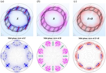
Simulation studies have been conducted with COMSOL, shown in figure 2, to demonstrate that the fields produced by the RF antenna configuration do indeed agree with the description given above. These E and B fields are oscillating quantities, so that the time average becomes zero. This leaves only the E × B that propagates azimuthally around inside. With Ez × Br, according to the Lorentz force, charged particles accelerate along the azimuthal direction by the E × B drift. In the initial formation phase, it is predicted that the electrons move faster than the ions due to the large mass difference. Thus, the initial plasma current is carried mostly by the electrons. However, the ions eventually catch up with the electrons, since the E × B drift accelerates both the ions and electrons. Thus we require some other means to hinder the motion of ions for this type of current-drive to properly operate.
Electromagnetic fields of the RF antenna configuration, where (a) is the electric field E, (b) is the magnetic field B and (c) is E × B. Below each image is the mid-plane cut section at the centre of the RF antenna configuration. The main component in interest is indicated by the arrow.

3. Suppression of ion drift motion with diamagnetic drift
When observing the momentum equation by taking the cross-product with B for both the ions and electrons, it is possible to notice several factors that influence current-drive. The following analysis is for the mid-plane section that assumes an infinitely long FRC. The effectiveness of the current-drive is expected to drop at each end of the RF antenna. Slightly beyond this is where the X-point is located. The main flow of current-drive is in the θ direction. Due to the AC fields, only time-averaged terms are of interest. There are four major terms shown in figure 3. The field produced by the RF antenna gives rise to the vCD term, RF current-drive. This is the main term that is responsible for current-drive. However, not only does it accelerate the electrons but also the ions. As charged particles accelerate, resistivity acts to reduce vCD. This term is denoted by vη, resistive drift, which has influence on both the electrons and ions.
Various drift velocities are involved for current-drive. There are four major components: diamagnetic drift, RF current-drive, resistive drift and E × B drift. The left side shows how the total ion drift velocity could be suppressed, while the right side displays acceleration of the electrons.

As the FRC starts to build up, a density gradient beings to form. This gives rise to a very important term, which is the diamagnetic drift. The diamagnetic drift for the ions vDi opposes the direction of vCD, such that ion rotation is suppressed. On the other hand, the diamagnetic drift for the electrons vDe provides extra acceleration to the electrons. Another drift that forms is the E × B drift, vE × B. For FRCs with RMF current-drive the radial electric field Er is pointed in the inward direction from the wall (Yambe et al. Reference Yambe, Inomoto, Okada, Kobayashi and Asai2008). The vE × B provides further acceleration to the electrons and also, unwantedly, to the ions.
For this method the main key to current-drive relies on having the ion drift velocity viθ almost equal to zero. This is where the diamagnetic drift term plays an important role by cancelling the ion acceleration due to vCD, while providing further acceleration to the electrons. It may also be likely for small-scale devices that the neutral density and charge exchange as well as the rather large Larmor radius of ~5 cm contribute to stagnating the ion flow. Thus, current-drive due to this type of RF antenna configuration is mostly driven by the electrons.
4. Features of the FRC device
The vacuum chamber of the device has a total length of 2 m with a diameter of 0.45 m at the centre, as shown in figure 4. The centre section is where the FRC is formed and sustained. The actual size of the FRC is estimated to be approximately 0.45 m in length, having a diameter of 0.3 m. There are a total of 10 magnetic coils (KR TECH) surrounding the outside of the vacuum chamber. Due to the tight spacing between the magnetic coils, only 4 ports are available for inserting diagnostics at the centre. Additionally, there are 4 ports to inject microwaves at 45° that could temporary be used for diagnostics if required.
Schematic of the O8-A device: (a) side view and (b) cross-sectional view. At the centre is where the FRC is formed and sustained by the RF antenna. For display purposes, part of the RF antenna used for current-drive is exposed. Several alumina plates are placed on top. Passive stabilizers are shown at each end of the centre section.

To produce current-drive, RF antennas are positioned inside the vacuum chamber. There have been other FRC devices that demonstrate the use of internal RMF antennas (Yambe et al. Reference Yambe, Inomoto, Okada, Kobayashi and Asai2008; Shi et al. Reference Shi, Ren, Zheng and Sun2018; Yanai, Takahata & Inomoto Reference Yanai, Takahata and Inomoto2018). To secure several coils in place, a structure made out of Teflon material nests all the coils. This structure is covered by alumina plates, a non-conducting material, which act as the first wall.
A total of four 2.45 GHz microwave generator (RFHIC), of 3 kW each, are planned to be in use for pre-ionization and to increase the pressure gradient if possible. At the end of the centre section are passive stabilizers, which are basically cone-shaped copper plates. It is predicted that having passive stabilizers at each end could provide extra stability to the FRC (Ji et al. Reference Ji, Belova, Gerhardt and Yamada2007).
The average density is targeted to be in the range of ~1018 m−3. By applying the pressure-balance relation, with the assumption of the electron temperature Te being equal to the ion temperature Ti, the range of Te are 25 to 150 eV corresponding to the external field Be of 15 to 35 mT. These are estimated values. In reality, the performance of the O8-A device is dependent on how well the RF antennas effectively provide current-drive.
5. Schematics of the FRC device
To supply current for the magnetic coils, 10 programmable DC power supplies (EX30-60, ODA Technologies) are in use. Capable of supplying 60 A for each magnetic coil, the centre axial field is able to reach 0.035 T, which should lie well within the operational range. Since the pulse length is expected to be ~10 ms, the DC power supply is momentarily switched on--off for several seconds during the plasma shot.
The power supply (DAWONSYS) for the RF antennas is capable of providing 100 A to each RF coil, with 50~100 kHz using SiCFET for generating the sinusoidal current waveform. However, the operational range is limited to 80~100 kHz due to the inductor-capacitor (LC) matching box placed at the end of each RF coil. There are a total of 8 power supply modules, each having 2 kW (total 16 kW), which supply AC current to 16 RF coils.
A total of 5 different diagnostics are planned to be in use. To measure the excluded flux radius, ~30 channels each, flux loops and magnetic probes span across the axial length of the magnetic coils. To determine whether field reversal is achieved, a 2-axis magnetic probe having multiple measurable points in the radial direction is scheduled to be used. Electron temperature and density will be measured by the double Langmuir probe. The line average density is determined by the millimetre-wave interferometer. The operating frequency can be varied from 50 to 75 GHz with a frequency multiplier, where the optimum probing frequency depends on the electron density. Schematics of the power supply and diagnostic layout are shown in figure 5.
Layout of (a) power supply, where three different types of power supplies are in use. The DC power supplies 1~10 are for the magnetic coils, W 1~4 are for generating microwaves and pulsed power is used to supply AC current to the RF antennas. Shown in (b) is the diagnostic layout of the device.

6. Summary
The main objective of the O8-A device is to apply a unique RF antenna design, which could presumably operate more efficiently than the RMF current-drive. The proposed current-drive works by producing Ez × Br to accelerate the electrons, while impeding the motion of ions through the diamagnetic drift. In addition, the use of passive stabilizes at each end of the device with the effect of 2.45 GHz microwave injection will be investigated. Various vacuum components, power supplies and magnetic coils are presently being manufactured. The first plasma is expected to be in late 2025.
Acknowledgements
The authors would like to acknowledge useful discussions and technical support from J.S. Im, G.Y. Choi, H.H. Lim, J.H. Park and B.S. Kim.
Editor Cary Forest thanks the referees for their advice in evaluating this paper.
Declaration of interests
The authors report no conflict of interest.
Funding
This work was supported by the National Research Foundation of Korea(NRF) grant funded by the Korea government(MSIT). (No. 2022R1A2C3005042).