Introduction
Radio-frequency identification (RFID) tag is an emerging wireless technology which automatically captures the data to recognize the identity of the remotely placed objects [Reference Preradovic and Karmakar1–Reference Finkenzeller4] using RF energy. The RFID tag has an excellent ability to identify the remotely located objects due to its various advantages over barcode [Reference Finkenzeller4] because of its long-range and no-line-of-sight reading capabilities [Reference Finkenzeller4]. The use of RFID tags in industry, commerce, telecommunication, tracking systems, and health monitoring has been significantly increased due to their simple circuitry, low cost, and data sensing abilities [Reference Preradovic and Karmakar1–Reference Borgese, Dicandia, Costa, Genovesi and Manara13]. The existing RFID technology can be categorized into chip based and chipless RFID tags [Reference Preradovic and Karmakar1–Reference Dey, Saha and Karmakar3]. The chip-based RFID tags have been extensively studied for sensing and encoding applications. However, these tags result in several shortcomings for narrowband applications such as complexity, durability, cost, and detection capabilities due to the use of integrated chip (IC). The presence of an IC which stores the data makes the RFID system costly and complex [Reference Preradovic and Karmakar1]. To reduce the cost of the chip-based RFID tag, many researchers have investigated ways to develop RFID tag without IC [Reference Preradovic and Karmakar1–Reference Dey, Saha and Karmakar3]. A passive chipless RFID sensor reduces the overall complexity of the RFID system as it does not require any external power source, microcontroller, or integrated circuitry and thus requires no maintenance hence reducing the cost of the RFID systems [Reference Preradovic and Karmakar1–Reference Finkenzeller4]. A wide range of passive chipless RFID sensors have been designed by different researchers in [Reference Javed, Habib, Amin, Loo, Akram and Tenhunen5, Reference Catarinucci, Colella and Tarricone6, Reference Preradovic and Karmakar14–Reference Shrestha and Karmakar49]. RFID tags for encoding applications have been reported in [Reference Preradovic and Karmakar14–Reference Khan, Tahir, Farooqui, Shamim and Cheema19]. Different RFID tag sensors for humidity [Reference Javed, Habib, Amin, Loo, Akram and Tenhunen5, Reference Catarinucci, Colella and Tarricone6, Reference Amin, Bhuiyan, Karmakar and Winther-Jensen20–Reference Amin and Karmakar25], temperature [Reference Catarinucci, Colella and Tarricone6, Reference Amin, Karmakar and Winther-Jensen26–Reference Jatlaoui, Pons and Aubert38], pressure [Reference Jatlaoui, Pons and Aubert38–Reference Thai, DeJean and Tentzeris43], and crack sensing [Reference Kalansuriya, Bhattacharyya, Sarma and Karmakar45–Reference Marindra and Tian48] applications have been reported. PEDOT [Reference Amin, Bhuiyan, Karmakar and Winther-Jensen20, Reference Amin, Saha and Karmakar24, Reference Amin and Karmakar25], graphene [Reference Amin, Saha and Karmakar24], metallic oxide [Reference Amin, Saha and Karmakar24], Kapton [Reference Dey, Saha and Karmakar3, Reference Javed, Habib, Amin, Loo, Akram and Tenhunen5, Reference Amin, Bhuiyan, Karmakar and Winther-Jensen20, Reference Feng, Xie, Chen and Zheng21, Reference Amin, Saha and Karmakar24–Reference Amin, Karmakar and Winther-Jensen26], FR4 [Reference Vena, Perret, Tedjini, Tourtollet, Delattre, Garet and Boutant18], single-walled carbon nano-tube [Reference Amin, Saha and Karmakar24] are the smart materials reported in the literature to design different RFID sensors. Although several unique aspects are presented in the literature, however some aspects such as high code density, complexity, noise reduction, angular, and polarization stability have not been thoroughly investigated in the state-of-the-art designs. This research presents a high coding capacity, inexpensive, miniaturized, easy to fabricate frequency-selective surface (FSS) [Reference Munk50–Reference Kiani, Ford, Esselle, Weily and Panagamuwa52] based RFID sensor tag for encoding and sensing applications. In this research, an easy and unique way of humidity sensing is adopted for which Kapton is used as a sensing material by employing it on the sensing bit as its relative permittivity is sensitive to relative humidity (RH). High radar cross-section (RCS), polarization and angular stability, low code density, high magnitude of frequency signatures, miniaturization, mitigation of noise generated by the coupling effects, item identification of 211 items, and RH sensing are the unique aspects of this research. All these characteristics have made the sensor tag a potential device for both encoding as well as sensing applications.
CS-RFID design
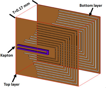
The simulations of the proposed tag were performed in the commercially available electromagnetic simulation software CST Studio “https://www.3ds.com/productsservices/simulia/products/cst-studio-suite/”. In this work, U-shaped resonators have been used to design the proposed tag on a Roger substrate 4350 having 16.98 mm×14.98 mm×0.17 mm dimensions. The relative permittivity, permeability, and dielectric loss tangent are 3.66, 1, and 0.004, respectively. Figures 1 and 2 are showing the 3D, top, and bottom view of dual-layer FSS-based tag, respectively. The tag is composed of a substrate which is sandwiched between the top and bottom layers having similar 2-D structure. To make it dual-layer FSS tag, identical structures of the same coordinates and dimensions are designed on the opposite sides of the substrate. The overall operation of the tag depends upon the dimensions and geometry of the resonating elements. The resonating frequency fr of the U-shaped resonators having specific length can be calculated using the following mathematical relation.


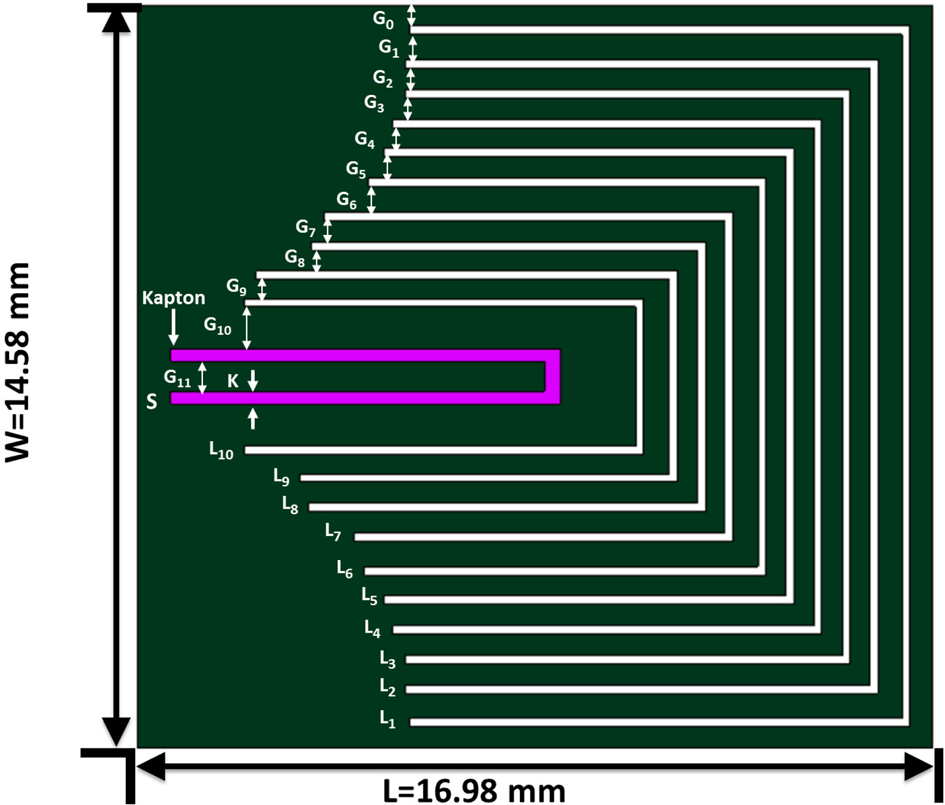
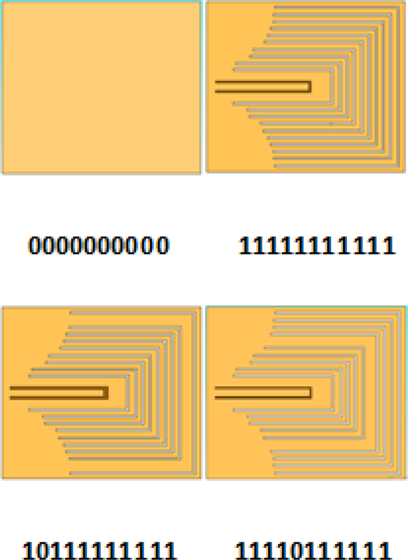
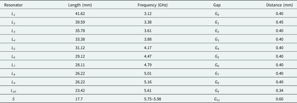
In the above equations, the length of the resonator, the speed of light, resonance frequency, the wavelength in free space, effective permittivity, and relative permittivity of the substrate are represented by L, c, f r, λ, ɛ eff, and ɛ r, respectively. However, the above equations give the approximate values of the resonators which are further optimized by adjusting different parameters of the resonators. Length of each resonator is represented by L1, L2, L3, L4, L5, L6, L7, L8, L9, L10, and S, whereas gaps between two consecutive resonators are represented by G0, G1, G2, G3, G4, G5, G6, G7, G8, G9, G10, and G11 for both top and bottom layers, respectively, as shown in Fig. 2. The lengths of U-shaped resonators are presented in Table 1. The proposed fabricated RFID tags for different data bits are shown in Fig. 3. All parameters of the fabricated tag are the same as defined in Table 1. The fabrication process is done in two steps. Firstly, the designed RFID tag has been fabricated for each layer and then Kapton® HN polyamide is placed on interior U-shaped resonator on both sides for RH sensing.
3D perspective view of top and bottom layer of 11-bit resonator.

Geometry and dimensions of the top and bottom layer of 11-bit resonator for item encoding and humidity sensing.

Front view of fabricated CS-RFID tag.

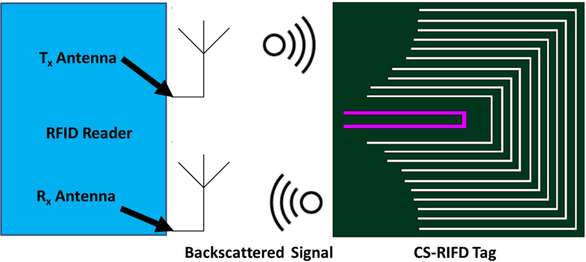
Communication between CS-RFID tag and RFID reader.

Dimensions of the proposed CS-RFID tag 3pt

Principle of operation
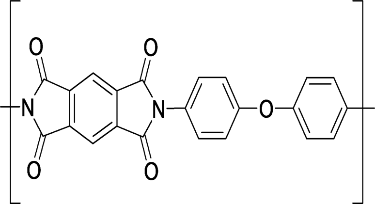
The proposed CS-RFID tag for item encoding works on the principle that presence of resonator gives a particular frequency signature treated as a data bit “1” while the absence of resonator shows a smooth curve in its RCS response and treated as a data bit “0” (Fig. 4). There is an inverse relationship between the length of the resonator and the resonance frequency as shown in equation (1). The external slot L 1 resonates at lowest frequency whereas L 10 resonates at the highest frequency. The proposed CS-RFID tag for RH sensing works on the principle of change in the dielectric permittivity of sensing material which will cause a negative frequency due to variation in RH. Consequently, an interior U-shaped structure having a minimum length as compared to the data encoding resonators is designed inside repetitive U-shaped resonators. This interior structure is resonating at a single particular frequency without covering it by Kapton® HN film. Later on, the interior structure is covered with Kapton® HN polyamide film which changes its dielectric permittivity with variation in RH. The RCS response of the sensor structure is dependent on the electrical properties of the substrate and covered material. Kapton® HN polyamide is temperature-sensitive from -269°C to +400°C. It is an aromatic polyamide, having an exceptional balance of chemical, electrical, and physical properties [Reference Amin, Karmakar and Winther-Jensen26]. It also possesses a linear dielectric change with humidity. Its dissipation factor varies from 0.0015 at 0% RH to 0.0035 at 100% RH [Reference Amin, Karmakar and Winther-Jensen26]. The linear change of Kapton's relative permittivity ɛr with RH is given by [Reference Amin, Karmakar and Winther-Jensen26]. Chemical structure of Kapton is presented in Fig. 5.

Due to the change in moisture level, a hydrolysis process occurs inside Kapton's structure, which results in variation of internal electric polarization. When water having weight proportional to humidity is absorbed between the free spaces of hygroscopic polymer, it changes the dielectric constant of Kapton molecule. This change in dielectric constant is directly proportional to the amount of water absorbed, and this variation of electrical polarization causes the shift in resonating frequency.
Chemical structure of Kapton.

Single-layer RFID tag
The dimensions of U-shaped resonators, sensor bit, and Kapton are the same for both single and dual-layer Kapton. However, for single-layer RFID tag, U-shaped resonators and Kapton have been designed on the single side of the substrate. Kapton has been employed on the interior bit which has been designed for RH sensing.
Dual-layer RFID tag
Dual-layer FSS-based RFID tag has U-shaped resonator layer on both sides of the substrate, to enhance the overall efficiency of the tag as shown in Figs 1 and 2. 3D and front view of dual-layer FSS-based RFID tag is presented in Figs 1 and 2. Each resonator is designed on the opposite sides of the substrate as per the dimensions which are subtracted from the top and bottom layer of copper employed on the roger substrate. In Fig. 2 exterior, 10 resonators are used for item encoding. Humidity sensing bit is represented by S. In Fig. 2, S and K are representing the sensor bit and width of Kapton, respectively. The dimensions of the sensing bit and U-shaped Kapton are the same. Kapton is placed above the interior U-shaped sensing bit S. The dimension of U-shaped Kapton employed on sensing bit S is 17 mm × 0.27 mm × 0.24 mm. The distance between the arms of U-shaped sensing bit and U-shaped Kapton is represented by G11 which is of dimension 0.6 mm as shown in Table 1.
Measurement setup for tagging
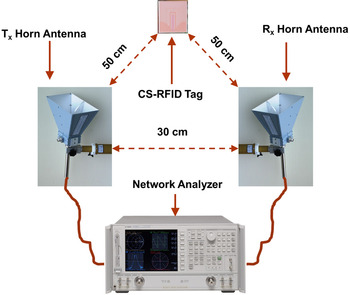
The experimental setup is shown in Fig. 6. Network analyzer from Agilent Technologies PNA-X N5242A of operating bandwidth of 10 MHz to 26.5 GHz is connected with two horn antennas having an operating bandwidth of 1–12 GHz with 12 dBi gain. The tag is energized through VNA using transmit power of 0 dBm in the frequency band of 2.5–7 GHz. The tag is located at 50 cm from two horn antennas separated by 30 cm which has been calculated using the Fraunhofer far-field distance. The parameter S 21 is measured and the calibration technique mentioned in [Reference Vena, Perret and Tedjini16] is used to extract the actual values of tag RCS. In this technique, three measurements of S 21 parameters are taken. Firstly, S 21 parameter without tag, secondly RCS of the known metallic rectangular sheet is measured, and finally, RCS of fabricated tag is measured to verify the simulated results.
Experimental setup to measure RCS response of CS-RFID tag for item identification.

Results and discussion
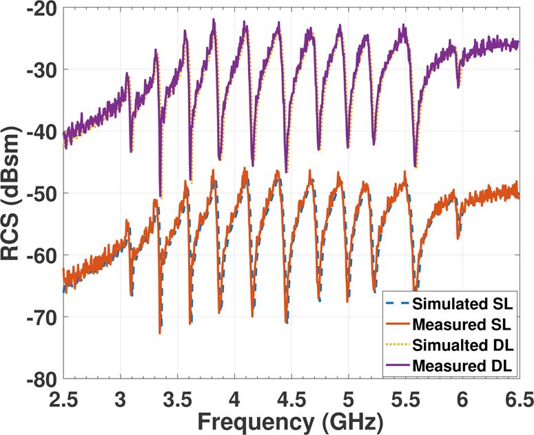
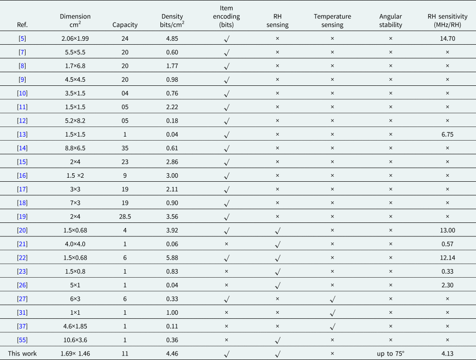
The simulated and measured results of single-layer RFID are presented in Fig. 7. Electrical noise can be experienced in any resistive/inductive electrical system, because of the thermal excitation of the electrons [Reference Lazaro, Villarino, Costa, Genovesi, Gentile, Buoncristiani and Girbau53]. Due to the low magnitude of frequency signatures, noise may distort or alter the frequency response of “0” or “1” bit. The noise was observed in the single-layer RFID tag while measuring the RCS response. The impact of noise is mitigated by optimizing the length and spacing of adjacent resonators. However, for single-layer, it is observed that the noise distorts the appearance of the most significant bit (MSB) as well as the least significant bit (LSB), as shown in Fig. 7. Simulated and measured results of dual-layer FSS-based RFID tag are also presented in Fig. 7. It is observed in the literature [Reference Javed, Habib, Amin, Loo, Akram and Tenhunen5, Reference Preradovic and Karmakar14, Reference Vena, Perret and Tedjini17–Reference Khan, Tahir, Farooqui, Shamim and Cheema19] that the LSB and the MSB are very small in magnitude. This small magnitude bit can easily be lost with noise. To overcome this drawback, large magnitude bits have been achieved by designing an FSS-based RFID tag to increase the magnitude of the RCS and to facilitate the detecting capabilities as suggested in [Reference Munk50, Reference Dobkin54]. It can be seen that MSB bits of the dual-layer RFID tag have two times larger magnitude than single-layer tag, whereas due to noise and smaller magnitude, the MSB of the single-layer tag cannot be recognized. Moreover, due to dual-layer FSS-based RFID tag, overall 0.45 MHz bandwidth has been increased which helps to recognize each bit effectively. The dual-layer RFID tag uses a spectrum of 3.23 GHz bandwidth while single layer tag uses a spectrum of 3.175 GHz. It can also be observed in Fig. 7 that besides the advantages of large magnitude bits, average RCS of the proposed tag is significantly improved as compared to single-layer RFID tag. It can be observed in Fig. 7 that the noise has been removed for MSB and LSB as compared to the single-layer RFID tag. The performance of the proposed RFID tag depends on various factors such as dimension, coding capacity, density, and sensing capabilities. A comparison of the proposed work with other reported literature is presented in Table 2. It can be seen that the proposed RFID tag has achieved highest coding capacity, angular stability up to 75°C, and RH sensing capability as compared to the state-of-the-art deigns. The coding density of each tag has been calculated using the following relation.

Where CD is the code density, CC is the code capacity, and A is the area of the proposed tag. With these 11 U-shaped resonators fabricated on a 16.98 mm×14.58 mm tag, 11 bits are encoded which resulted in code density of 4.46 bits/cm2. Although code density 3.56 bits/cm2 has been achieved in [Reference Khan, Tahir, Farooqui, Shamim and Cheema19], angular stability as well as sensing capabilities have not been achieved. While designing the proposed RFID, detuning effects are also considered and addressed to avoid any performance degradation of RFID tag. Firstly, U-shaped resonators are selected to handle the RFID tag with ease from the outer edges, as shown in Fig. 1. This empty space without the resonators can also be used to attach the proposed RFID tag with the objects to be identified. Secondly, Kapton is employed on the interior resonator to avoid any damages during the handling of tag and that is why it is not pasted on exterior resonator as done in [Reference Amin, Saha and Karmakar24]. Finally, the dimension of Kapton and sensing bit have been kept smaller to minimize the effects of glued material and moisture. To observe the behavior of dual-layer configuration when one side of the tag is glued to the identified items, RCS of the proposed RFID tag is measured in two ways. Firstly, RCS of the proposed RFID tag is measured without pasting it on the substrate. Secondly, the dual-layer RFID tag is glued to RO4350 substrate to calculate the impact of glued material and substrate. It has been noticed that RCS of the proposed RFID tag has been decreased to 0.2 dB whereas the resonance frequencies remain the same. Same phenomenon has been observed for single-layer RFID tag. So it is concluded that the benefits of the dual-layer RFID tag can be enjoyed in reality as well if the tag is glued to some identified objects. The impact of horizontal and vertical configuration of resonators on RCS and bandwidth has been investigated. Firstly, these resonators are designed and repeated horizontally along the x-axis as done in [Reference Vena, Perret, Tedjini, Tourtollet, Delattre, Garet and Boutant18, Reference Iqbal, Shahid, Riaz, Rauf, Amin and Tenhunen56]. But using this configuration, the noise has not been reduced and RCS is only improved up to 3 dB as compared to the single-layer RFID tag. Moreover, using the horizontal configuration presented in [Reference Vena, Perret, Tedjini, Tourtollet, Delattre, Garet and Boutant18, Reference Iqbal, Shahid, Riaz, Rauf, Amin and Tenhunen56], the size and density of the RFID tag have increased up to 100%. Finally, using the vertical/stacked [Reference Munk50] configuration, each resonator has been placed on the opposite side of the substrate by keeping the dimensions and periodicity of each resonator constant along the z-axis. As shown in Fig. 7, RCS of the proposed RFID tag has been improved while noise has also been reduced. As investigated in [Reference Munk50], wider bandwidth is the result of stacked/dual or multilayered FSS. FSS-based chipless sensor RFID (CS-RFID) tag has the following characteristics which have been significantly enhanced in comparison to the reported literature mentioned below:
• RCS of CS-RFID tag is significantly improved up to 40% as compared to the conventional single-layer RFID tag presented in [Reference Javed, Habib, Amin, Loo, Akram and Tenhunen5, Reference Catarinucci, Colella and Tarricone6, Reference Vena, Perret and Tedjini15–Reference Amin, Bhuiyan, Karmakar and Winther-Jensen20, Reference Amin, Bhuiyan, Karmakar and Winther-Jensen22, Reference Amin, Saha and Karmakar24, Reference Amin and Karmakar25, Reference Amin and Karmakar25–Reference Preradovic and Karmakar27, Reference Preradovic, Kamakar and Amin29, Reference Mahmood, Sigmarsson, Joshi, Chappell and Peroulis31].
• Polarization-independent angular stability for normal and oblique angle of incidence is ensured as compared to [Reference Javed, Habib, Amin, Loo, Akram and Tenhunen5, Reference Catarinucci, Colella and Tarricone6, Reference Preradovic and Karmakar14–Reference Vena, Perret and Tedjini17, Reference Khan, Tahir, Farooqui, Shamim and Cheema19–Reference Amin, Bhuiyan, Karmakar and Winther-Jensen22, Reference Amin, Saha and Karmakar24–Reference Mahmood, Sigmarsson, Joshi, Chappell and Peroulis31, Reference Thai, Chebila, Mehdi, Pons, Aubert, DeJean and Plana34, Reference Noor, Habib, Amin, Loo and Tenhunen35, Reference Vena, Sydänheimo, Ukkonen and Tentzeris37].
• Increasing the code density of the tag decreases the bandwidth of each identification bit. Bandwidth of the frequency signature for each identification bit is small in [Reference Javed, Habib, Amin, Loo, Akram and Tenhunen5, Reference Khan, Tahir, Farooqui, Shamim and Cheema19, Reference Noor, Habib, Amin, Loo and Tenhunen35] due to high code density. In this work, 50, 39, and 2% bandwidth of each identification bit has been increased as compared to [Reference Javed, Habib, Amin, Loo, Akram and Tenhunen5, Reference Khan, Tahir, Farooqui, Shamim and Cheema19, Reference Noor, Habib, Amin, Loo and Tenhunen35], respectively.
• Magnitude of the frequency signature has been enhanced up to 20 dB as compared to [Reference Javed, Habib, Amin, Loo, Akram and Tenhunen5, Reference Preradovic and Karmakar14–Reference Amin, Bhuiyan, Karmakar and Winther-Jensen20, Reference Amin, Bhuiyan, Karmakar and Winther-Jensen22, Reference Preradovic and Karmakar27–Reference Thai, Mehdi, Chebila, Aubert, Pons, DeJean and Plana30, Reference Thai, Chebila, Mehdi, Pons, Aubert, DeJean and Plana34, Reference Noor, Habib, Amin, Loo and Tenhunen35, Reference Vena, Sydänheimo, Ukkonen and Tentzeris37].
• Due to coupling effects, noise vanished the frequency signature of MSB in [Reference Javed, Habib, Amin, Loo, Akram and Tenhunen5, Reference Preradovic and Karmakar14, Reference Vena, Perret and Tedjini15, Reference Vena, Perret and Tedjini17–Reference Khan, Tahir, Farooqui, Shamim and Cheema19, Reference Thai, Chebila, Mehdi, Pons, Aubert, DeJean and Plana34, Reference Noor, Habib, Amin, Loo and Tenhunen35]. In this work, due to dual-layer FSS, the impact of noise is removed which has increased the significance and visibility of MSB.
• Moreover, miniaturization, item identification of 211 items, and humidity sensing are the most important aspects of this work. Miniaturization is achieved by integrating the RH sensor in the same RCS-based tag, making it low profile. To the best of our knowledge, such a flexible and multipurpose sensor tag has not been reported in the literature which has the capability of simultaneously measuring the RH as well as item encoding using the same RFID tag. All these characteristics have made the sensor tag a potential device for both encoding as well as sensing applications.
Simulated and measured RCS response of single-layer (SL) and dual-layer (DL) CS-RFID tag.

Comparison of various radio-frequency identification (RFID) tags reported in the literature 3pt

Current distribution
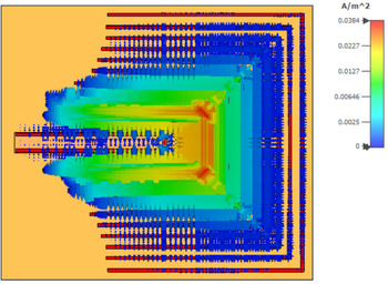
The operation and physics of the designed tag can be understood with the help of Fig. 8. The tag is excited by a uniform plane wave in z + direction. Figure 8 shows the higher surface current density at the center frequency of 4.5 GHz. The middle part of the CS-RFID tag has been concentrated by the higher surface current, indicating the inductive behavior of the tag. However, the concentration of surface current density on the other part of CS-RFID tag is relatively lower indicating the occurrence of capacitive behavior. The maximum amount of current is 0.0384 A/m2. The higher current densities at the center frequency 4.5 GHz is showing a reflection of the plane wave in z + direction.
Electric current distribution on the surface of the tag when excited with a linearly polarized plane wave at 4.5 GHz.

Angular and polarization stability
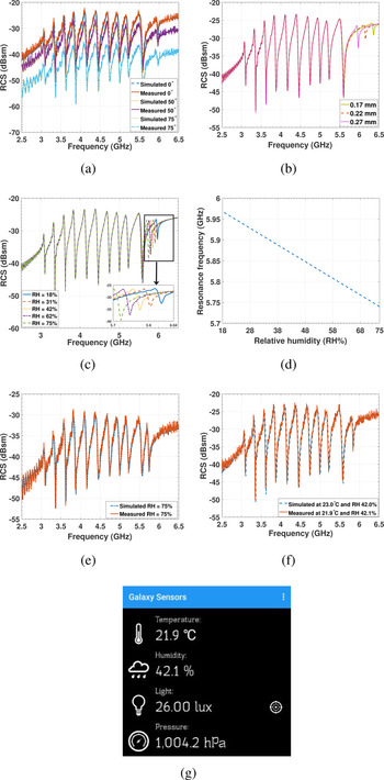
The simulated results for different angles of incidence have been achieved by doing a parametric analysis in CST MW Studio Suite. To measure the angular stability of the tag of 111111111111 for TE and TM polarizations, CS-RFID tag has been attached with polystyrene foam at a height of 44 cm. Polystyrene foam has been firstly placed normal to the Tx antenna to measure the S 21 at 0° angle of incidence. After that polystyrene foam has been rotated at an angle of 25°, 50°, and 75°, respectively, and thus S21 parameters have been measured. Simulated and measured results of 0°, 50°, and 75° are shown in Fig. 9(a). Angular stability has been achieved due to the proposed design. It has been observed that resonance frequencies have been unaffected for a normal and oblique angle of incidence while the magnitude of the bits remains unchanged. However, a downward shift for each bit has been observed at 50° and 75° angle of incidence yet the overall frequency response of the proposed RFID tag has been stable. The downward shift shows that RCS of the designed tag decreases with the increase in the angle of incidence.
(a) Simulated and measured RCS response of CS-RFID tag at 0°, 60°, and 75° angles of incidence. (b) Simulated RCS response of CS-RFID tag for different thickness values of Kapton. (c) Simulated RCS response of CS-RFID tag at different RH levels. (d) Resonant frequency versus RH for Kapton employed on the sensing bit. (e) Simulated and measured RCS response of CS-RFID tag at 75% RH. (f) Simulated and measured RCS response of CS-RFID tag at temperatures of 23 and 21.9°C and RH levels of 42 and 42.1%, respectively. (g) Temperature and humidity measurement using Galaxy sensors.

Relative humidity sensing
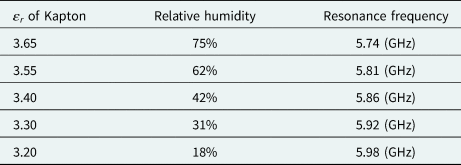
The proposed and fabricated tag has also been designed to monitor the RH. To optimize and to enhance the magnitude of the sensing bit, the RCS response of CS-RFID tag has been observed for different thickness values of the Kapton as shown in Fig. 9(b). It has been observed that the magnitude of the sensing bit is increasing by increasing the thickness of the Kapton. The magnitude of the sensing bit has been significantly improved at 0.27 mm as shown in Fig. 9(b). The same RFID tag has been used for RH monitoring for different dielectric values using equation (4), by keeping the thickness of Kapton 0.27 mm. The humidity sensor responses have been observed for 18, 31, 42, 62, and 75% RH levels for the dielectric permittivity values of 3.20, 3.30, 3.40, 3.55, and 3.65 of Kapton polyamide, presented in [Reference Amin, Karmakar and Winther-Jensen26], respectively. As a result, interior resonator shows a negative frequency drift as shown in Fig. 9(c). Moreover, theoretical results show that the resonance frequency of only sensing bit has been changed with a variation in humidity while remaining resonance frequencies of ID encoding bits remain unchanged. From 18 to 75% RH change, the overall shift in the resonance frequency is 240 MHz. So for 1% RH change, there is 4.5 MHz shift in frequency as shown in Fig. 9(d). A comparison of RH sensitivity (MHz/1% RH) for the humidity sensors proposed by different researchers is also presented in Table 2. To validate the simulation results, RH sensing of the proposed tag was measured by maintaining the room RH at 75%. RH of the room has been maintained at 75% by placing a saturated solution of NaCL in a beaker of 500 ml [Reference Virtanen, Ukkonen, Bjorninen, Elsherbeni and Sydänheimo55, Reference De Goffau, Yang, Van Dijl and Harmsen57]. The simulated and measured results of the tag at 75% are shown in Fig. 9(e) having resonance frequency of 5.748 GHz which is very close to the value presented in Table 3. It has been observed that there is a good agreement between the simulated and measured results. A small negative drift in frequency can be observed which also validates the simulated results. At 23°C temperature, the relative permittivity of Kapton is 3.4 and RH is 42% [Reference Amin, Karmakar and Winther-Jensen26]. It has been verified as well that at 21.9°C, RH of the room is about 42.1% which is very close to the 42% RH value mentioned in [Reference Amin, Karmakar and Winther-Jensen26], as shown in Fig. 9(f). At 21.9°C, RH is 42.1% having a resonance frequency of 5.86 GHz, as shown in Fig. 9(g).
Relative humidity matrix 3pt

Item encoding
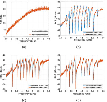
The primary purpose of the proposed tag is the encoding of different items. The proposed tag can encode 211 items. To validate this claim, a combination of different bits is simulated and measured. The results of four different CS-RFID structures are shown in Figs 10(a)–10(d). To avoid the microwave scattering, the tag is attached to the polystyrene foam. Firstly, the proposed RFID tag is simulated and measured without any resonator encoded by 00000000000, as shown in Fig. 10(a). A decaying curve can be seen in the figure from higher frequencies to the lower frequencies. In Fig. 10(b), a combination of 11111111111 is simulated which results in 11 unique frequency signatures. In Fig. 10(c), simulated and measured results of 1011111111 are shown. It is shown that by removing the resonator, a frequency signature is replaced with a smooth curve. The same idea is used for 11110111111 which is verified in Fig. 10(d).
Simulated and measured RCS response of (a) 00000000000, (b) 11111111111, (c) 10111111111, (d) 11110111111.

Conclusion
A miniaturized, lightweight, and high encoding capacity 11-bit RFID tag possessing humidity sensing capabilities is validated through simulated and experimental results. Frequency band expansion, as well as angular stability, is ensured along with enhancing the magnitude bit using dual-layer FSS-based RFID tag. RH sensing has been realized on the same tag making it low-profile. It can be used for tracking different consumers and pharmaceutical products along with measuring their RH levels.
Acknowledgement
This work was supported by the provision of a cooperation license for CST Studio Suite by Dassault Systems.
 Shahid Habib has received his M.Sc degree in Electronics from Quaid-e-Azam University in 2005 and completed his MS in Electronic Engineering from ISRA University in 2011. He is currently pursing doctoral degree in Electrical Engineering at COMSATS University, Islamabad, Pakistan. He has more than 12 years experience of telecommunication industry and worked as a Field Operations manager and specialist. He is an active member of Next Generation Communications Research Group in the Department of Electrical and Computer Engineering, COMSATS University Islamabad, Pakistan. So far he has published five conference and two journal papers. His expertise and research interests are frequency-selective surfaces (FSS), radio Frequency identification (RFID), FPGA-based communication system design, and optical Fiber communication system.
 Amjad Ali received the B.Sc. degree in Electrical Telecommunication Engineering from COMSATS University Islamabad, Pakistan, in March 2014. He received M.Sc. degree in Telecommunication Engineering from the University of Engineering and Technology Taxila, Pakistan, in December 2017. He joined ACTSENA research group in 2017. Amjad Ali is currently pursuing his Ph.D. degree in Electrical Telecommunication Engineering from the Department of Electrical and Electronics Engineering, University of Nottingham, UK. His research interest is designing chipless RFID tags for tracking biomass pellets supply chain and monitoring their ambient humidity, temperature, and CO2 level. He joined GGIEMR Research Group in 2018 at the University of Nottingham, UK.
 Ghaffer Iqbal Kiani received the B.Sc. degree in Electrical and Electronic Engineering (with first-class distinction) from the Islamic University of Technology, Dhaka, Bangladesh, in September 1997, the M.Sc. degree (with first-class high distinction) in Electronic Engineering from Ghulam Ishaq Khan (GIK) Institute of Engineering Sciences and Technology, Topi, Pakistan, in May 2003, and the Ph.D. degree in Electronic Engineering from Macquarie University, Sydney, Australia, in May 2009. From July 2009 to July 2012, he was a Postdoctoral Fellow in very-high throughput wireless communication systems at Commonwealth Scientific and Industrial Research Organization (CSIRO) ICT Centre, Sydney, Australia. From March 2013 to date, he is working as an Assistant Professor at the Department of Electrical and Computer Engineering, King Abdulaziz University, Jeddah, KSA. Dr. Kiani has published many high-quality research papers in the field of Antennas and Propagation. His current research interests include frequency-selective surfaces, metamaterials, electromagnetics, antenna design, microwave polarizers, MEMS, NEMS, RFIDs, and THz modulators. Dr. Kiani was awarded the Best Student Paper Award at the 2008 Workshop on Applications of Radio Science (WARS) Conference, Gold Coast, Australia, for the paper, “Transmission Improvement of Useful Signals through Energy Saving Glass Windows using Frequency Selective Surfaces”.
Wagma Ayub received B.S Chemistry from Islamia College Peshawar, Pakistan in 2013 and M.Phil Chemistry from Quaid-I-Azam University, Islamabad, Pakistan in 2016. From July 2016 to January 2017, she worked as a research assistant in Higher Education Commission Pakistan's funded project. Since 2018, she is pursuing Ph.D. in the School of Chemistry, University of Nottingham, UK on a project related to flow chemistry and Pd catalyzed reactions.
 Syed Muzahir Abbas received the B.Sc. degree in Electrical (Telecommunication) Engineering from the COMSATS Institute of Information Technology (CIIT), Islamabad, Pakistan, in 2006, the M.Sc. degree in Computer Engineering from the Center for Advanced Studies in Engineering (CASE), Islamabad, Pakistan, in 2009, and the Ph.D. degree in Electronics Engineering at Macquarie University, North Ryde, NSW, Australia, in 2016. He has been a Transmission Engineer for Alcatel-Lucent, Pakistan, RF Engineer with CommScope, Australia, and Senior Antenna Design Engineer with Benelec Technologies, Australia. He has lectured various courses at CIIT, Islamabad, Pakistan, and in Australia with Western Sydney University, Macquarie University, and University of Sydney. Currently, he is working as a Senior Principal Engineer with Benelec Technologies, Australia. He has been a visiting researcher at ElectroScience Laboratory, Ohio State University, USA, and Queen Mary University of London, UK. He has also received several prestigious awards and fellowships, including 2019 IEEE NSW Outstanding Young Professional Award, 2018 Young Scientist Award (Commission B – Field and Waves) from the International Union of Radio Science (URSI), 2013 CSIRO Postgraduate Fellowship, 2012 iMQRES Award for Ph.D., and Research Productivity Awards in 2012 and 2010 from CIIT, Pakistan. His research interests include base station antennas, mmWave antennas, high-impedance surfaces, frequency-selective surfaces, flexible/embroidered antennas, CNT yarns, CNT/graphene-based antennas, reconfigurable antennas/electronics, and the development of antennas for UWB and WBAN applications.
 Muhammad Fasih Uddin Butt received B.E. degree from the National University of Sciences and Technology (NUST), Pakistan in 1999. He received his M.E. degree from the University of Engineering and Technology Taxila, Pakistan with specialization in Digital Communication/Computer Networks in 2003 and his Ph.D. in Electronics and Electrical Engineering from the School of Electronics and Computer Science, University of Southampton, UK in June 2010. He is a Tenured Associate Professor and the Head of Next Generation Communications Research Group in the Department of Electrical and Computer Engineering, COMSATS University Islamabad, Pakistan where he has been serving as an academic since 2002. Currently, he is a visiting academic in the School of Electronics and Computer Science, University of Southampton, UK. His research interests include channel coding, cooperative cognitive radio networks, mmWave radio-over-fiber technologies, physical layer security, quantum communications, massive IoT, and frequency-selective surfaces. He has published over 45 research papers in various reputed journals and conference proceedings.