1. Introduction
Soil sampling is required in several scenarios involving modern agriculture, construction, environmental analysis, or, in the marine domain, concerning offshore engineering and seabed mineral analysis. In recent years, several robotic platforms have been developed for sample collection. The work in ref. [Reference Edulji, Soman, Pradhan and Shah1] presents a proof-of-concept demonstrator of a semi-autonomous robotic system for collecting soil samples, where a mechanical soil sampling and a storage system based on augers and turntable storage are used, and where the robot autonomously navigates to desired sampling locations. The paper in ref. [Reference Chiodini, Carron, Pertile, Todescato, Bertolutti, Bilato, Boscardin, Corra, Correnti, Dalla Vecchia, Dal Lago, Fadone, Fogarollo, Milani, Mion, Paganini, Quadrelli, Soldà, Todescan, Toffanin and Debei2] presents a planetary-like rover designed by a team of students as a testbed for planetary robotic exploration, like soil and rocks extraction and sampling, and for autonomous navigation in unstructured environment. In ref. [Reference Olmedo, Barczyk, Zhang, Wilson and Lipsett3], an unmanned ground vehicle with a custom-built robotic manipulator for oil sampling and terramechanics investigations is presented. The paper in ref. [Reference Vaeljaots, Lehiste, Kiik and Leemet4] presents the case study of a robotic soil sample collection system from bottom to top, where the sampling process automation is solved by using the robotic platform and electro-hydraulic mechanism, while the control system is connected with a cloud-based software that enables to create and manage the operation tasks. The work in ref. [Reference Väljaots, Lehiste, Kiik and Leemet5] presents the mechanical design of a soil sampling device and the control software of a mobile robotic platform for precision agriculture. The work in ref. [Reference David, Yumol, Garcia and Ballado6] presents a prototype of two ground robots developed, as a team of a robotic swarm, to collect soil samples. The paper in ref. [Reference Yokoi, Kawabata, Sakai, Kawamura, Sakagami, Matsuda, Mitsui and Sano7] presents a human-portable underwater robot for soil core sampling in the underwater domain; the paper in ref. [Reference Isaka, Tsumura, Watanabe, Toyama, Sugesawa, Yamada, Yoshida and Nakamura8] presents a drilling robot, based on earthworm locomotion, that was developed for seafloor exploration, while the work in ref. [Reference Isaka, Tsumura, Watanabe, Toyama, Okui, Yoshida and Nakamura9] presents a seafloor robotic explorer that can excavate and sample seafloor soil, with a discharging mechanism utilizing water jetting to improve the excavation depth.
Environmental sampling is required in several scenarios characterized by the existence of a pile of land made by potentially contaminated soil. Current Italian legislation requires to sample a representative amount of soil within a range of
 $2\div 4$
kg, depending on the total volume of soils present in the area under investigation, that has to be sent to chemical laboratories for the successive analysis. More in detail, this operation, named quartering, consists in sampling several amounts of soils in specific 3D positions that have to be mixed together. Such activity is currently done manually, which is a tautologically dangerous process given the potential contamination of the site under analysis. The project ROBILAUT, funded by the Italian Ministero dello Sviluppo Economico (Ministry of Economical Development), had the objective to automatize the overall operation with benefits for the operators’ health, to improve the representativeness of the sample and to decrease the operation’s costs. In a first phase, an operator manually drives a drone in charge of building a 3D model of the soil pile; in the considered case, the pile is up to
 $3000$
m
 $^2$
with an height of approximately
 $3$
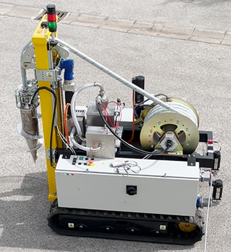
m. Then, the CAD model is sent to a motion planning engine which, taking into account the legislation constraints and the energy-related optimizing criteria, outputs the points where the samples need to be taken. Once the sampling point list is obtained, then the ROBILAUT robot, shown in Fig. 1, autonomously drives toward them and samples/mixes the specific amount of soil under the supervision of an operator that monitors the overall process using a properly developed graphical user interface (GUI). Indeed, the operator is not in the line of sight with the vehicle due to the pile height (usually 3 m); thus, there is the need to supervise the process and eventually activate an emergency procedure. The GUI is compatible with multiple devices over a local network; thus, the monitoring can eventually be shared or done remotely.
Side view of the ROBILAUT robot: a crawler vehicle equipped with a driller to perform potentially contaminated soil sampling.

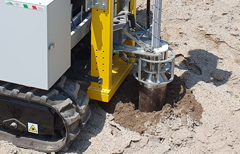
Fig. 2 shows the drilling operation which, however, is beyond the scope of this paper.
Snapshot of the ROBILAUT robot during drilling, a mechanical sampling mechanics is embed in the head and allows for the required quartering task.

2. System overview
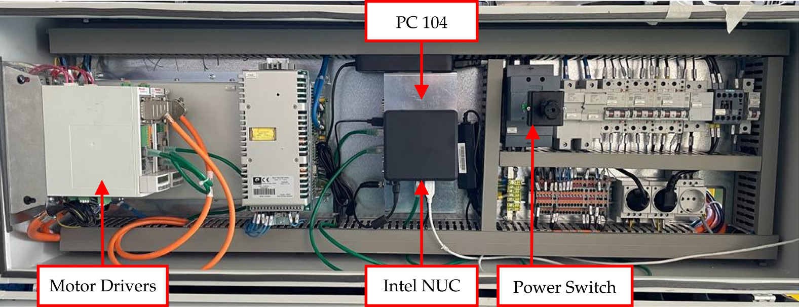
The robotic system developed within the ROBILAUT project is represented by a crawler vehicle equipped with a tethered drilling device. The vehicle carries all the computing modules, installed in a proper electrical automation cabinet shown in Fig. 3, and all the sensors needed to perform the autonomous navigation, that is:
Electrical automation cabinet containing the computing modules (Intel NUC and PC-104 class device), the motor drivers, and the general Power Switch.

an Intel NUC PC used for the acquisition and processing of the data from the inertial sensors and the localization module, and for the execution of the navigation control algorithm;
an industrial computing module (PC-104 computer class), linked to the crawler motor drivers, dedicated to setting the desired velocities from the control output and reading the current motor status;
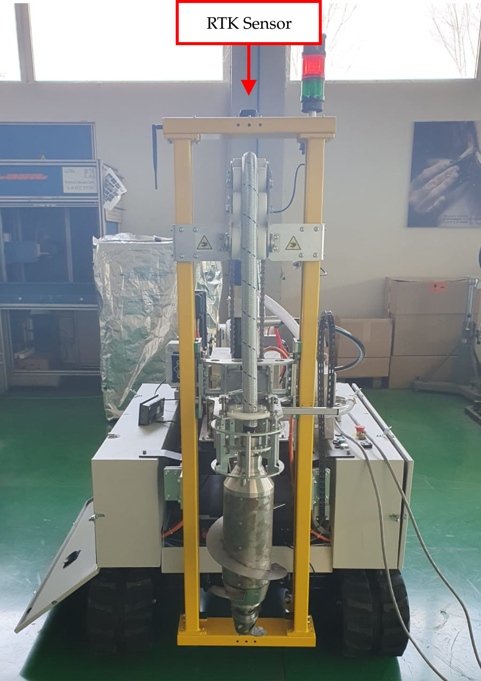
a localization module based on global navigation satellite system (GNSS) technology; specifically, a real-time kinematic positioning (RTK) system which represents the most performing method to correct the errors in current GNSSs, obtaining an accuracy of the order of cm [Reference Feng and Wang10]. Such a system uses both information content and wave phase of satellite signals, and it relies on a set of ground reference stations to mitigate the atmospheric effects, for example, the ionospheric delay on the measured distance. The set of ground reference stations can include only one station; however, the latter has to be positioned within a distance of
 $50$
km from the target that needs to be localized. This is the case of the ROBILAUT system where a commercial RTK kit is used, that is, the ArduSimple Starter kit, which includes two GNSS receivers: one installed on top of the vehicle (as shown in Fig. 4) and one to be used for the ground station. The two receivers are equipped with two long-range modules that allow the communication for the localization correction;
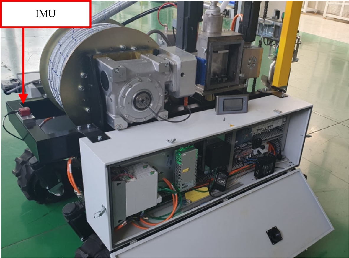
an inertial measurement unit (IMU), installed in the back of the ROBILAUT vehicle, for minimizing interferences (see Fig. 5), represented by the Ellipse-E, a commercial solution provided by SBG Systems. This module includes an accelerometer, a gyroscope, a magnetometer, as well as a temperature sensor. Furthermore, it applies an internal data fusion algorithm, that is, a Kalman filter, to provide a better estimation of navigation data such as the vehicle yaw, which can be directly read from the magnetometer or taken from the data fusion algorithm output.
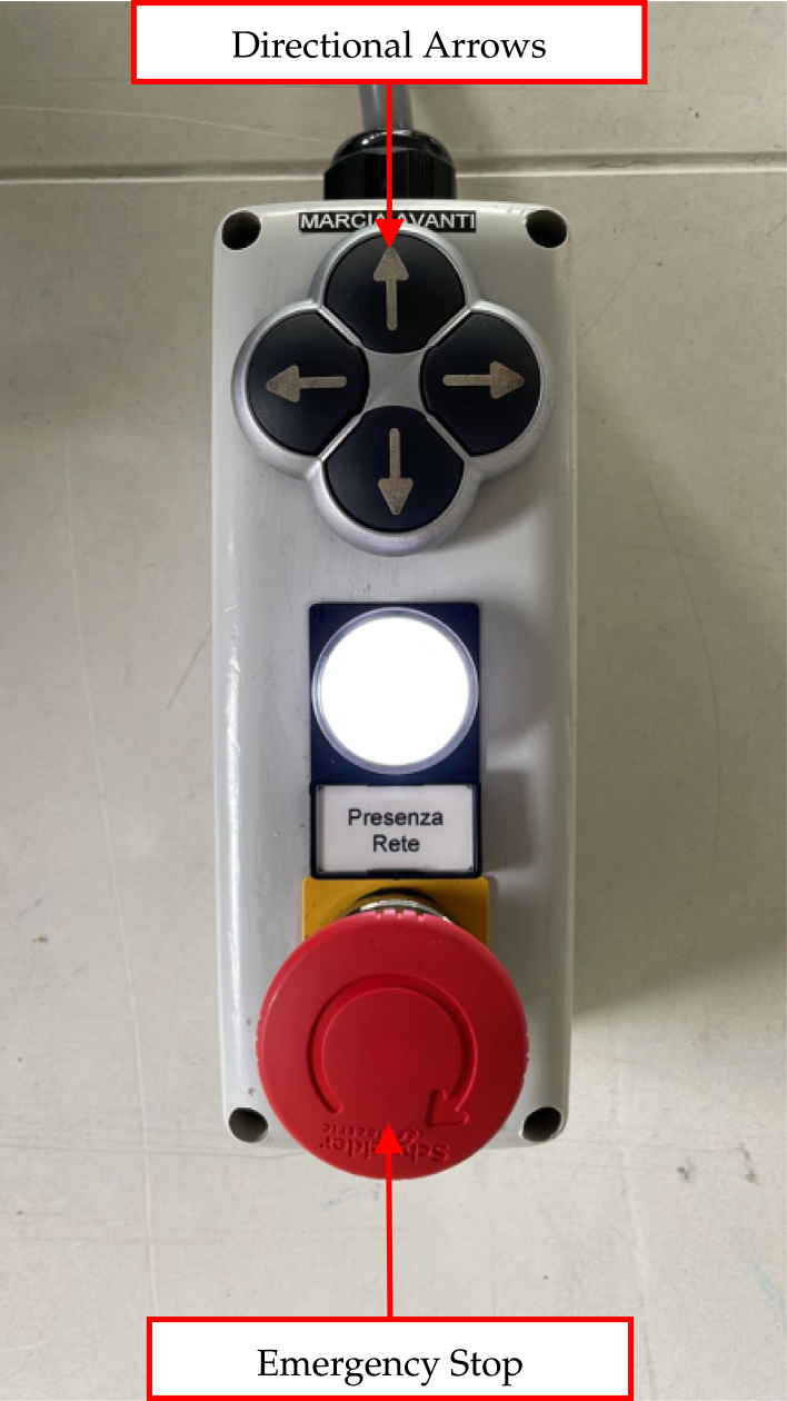
a joystick allowing the human operator to manually move the vehicle both for safety and logistics reasons (see Fig. 6); in addition to the direction (arrows) buttons, it is equipped with an emergency stop button to be used in dangerous situations, such as a person moving close to the vehicle during the parking maneuvers.

RTK-GNSS receiver installed on top of the ROBILAUT vehicle.

Ellipse-E IMU by SBG Systems installed in the back of the ROBILAUT vehicle for minimizing the interference.

Joystick for the manual movement of the ROBILAUT vehicle equipped with emergency button for safety reasons.

3. Overall software architecture
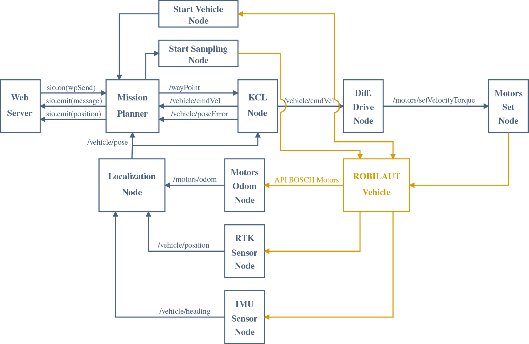
The software architecture has been developed using the robot operating system (ROS) middleware. Fig. 7 shows the overall architecture where each box represents the
 $i$
-th ROS node running the corresponding process and where each arrow represents a specific ROS topic used for data exchange. In particular:
ROBILAUT system software architecture based on the robot operating system (ROS) middleware.

Web server: it is the web server that runs the GUI exchanging data with an interface node through a socket. In particular, the GUI is used by the human operator to set the desired waypoints (sio.on(wpSend)) and to monitor the mission execution (textttsio.emit(message), sio.emit(position)). A more detailed description of the GUI is reported in Section 3.1.
Mission planner: it is the node that acts as the bridge between the GUI web server using Python sockets and the ROS middleware. It receives as input the desired waypoints (sio.on(wpSend)) for the control node (/wayPoint), the trigger to let the vehicle start the movement, the vehicle pose (/vehicle/pose), the pose error (/vehicle/poseError), and the reference velocity (/vehicle/cmdVel). Then, it sends the current vehicle status back to the GUI web server (sio.emit(message), sio.emit(position)). It is also in charge of sending the starting trigger for the sampling operations.
KCL node: the kinematic control layer (KCL) node runs the implemented controllers, described in Section 5, necessary to compute the reference velocity (/vehicle/cmdVel) for the vehicle to navigate following the desired waypoints (/wayPoint). The waypoint list and current vehicle pose (/vehicle/pose) represent the node input, while it returns as output the reference velocity (/vehicle/cmdVel) and the pose error (/vehicle/poseError).
Diff. drive node: since the vehicle presents a differential drive kinematics, as described in Section 4, this node is in charge to take the input reference velocity (/vehicle/cmdVel) and to map it into proper desired velocities for the two crawl motors that are sent to motors set node (/motors/setVelocityTorque).
Motors set node: it represents a ROS wrapper for the API provided by the motors supplier, that is, Bosch; therefore, it allows to interface the ROS middleware with the motors’ low-level controllers.
Motors odom node: it is a ROS wrapper for the Bosch API as well; in this case, the nodes give as output of the motor odometry data, that is, the motor velocity and position.
RTK sensor node: it is in charge of acquiring the data from the RTK module via HTTP requests, since the latter is interfaced with a micro web server implemented for the case at hand that converts the GNSS coordinates into the UTM (Universal Transverse Mercator) reference system, that is, North-East coordinates in meters. Then, position data are sent inside the ROS framework via the topic (/vehicle/position).
IMU sensor node: this is the ROS package provided by SBG which allows to access to every information regarding the sensor status. In the specific case, the vehicle heading is the data of interest (/vehicle/heading).
Localization node: this node runs a proper data fusion algorithm, that is, the Kalman filter, taking as input the data coming from motors, RTK and IMU sensor. It returns as output a noise-filtered and continuous signal (/vehicle/pose), necessary for the proper operative functioning of the controller, containing the robot pose estimate.
Start vehicle node: it reads the status of the drilling unit by querying the programmable logic controller (PLC) through a standard communication protocol, that is, the OPC UA (Open Platform Communications Unified Architecture). Indeed, before moving the vehicle, it is necessary to control that the system is not performing the sampling operation and that the drilling unit is in its home position. If all the related checks are verified, then the start vehicle node sends a trigger to the mission planner.
Start sampling node: this node waits for a trigger from the mission planner. Indeed, when the robot reaches the
$i$
-th desired point, the overall system movement is stopped and a consensus signal is sent to the start sampling node. Then, the latter interacts with the PLC via OPC UA, as mentioned for the start vehicle node. If the consensus is verified, then the PLC stars the drilling operation that is implemented according to a state machine approach.

3.1. Graphical user interface (GUI)
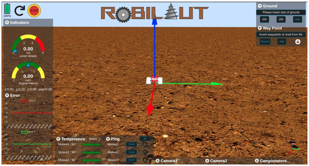
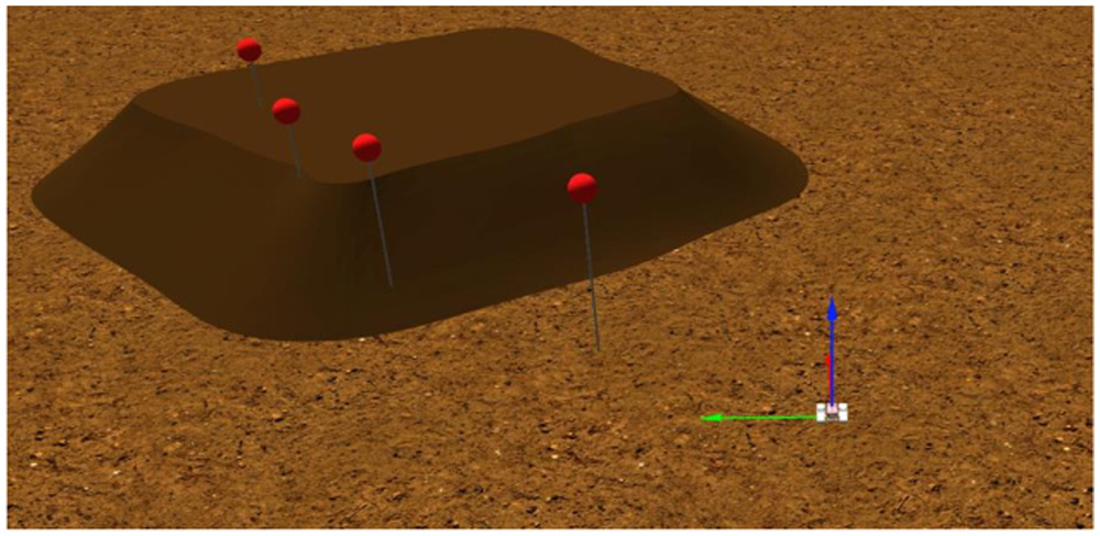
As mentioned above, the human operator is not in line of sight with the vehicle due to the soil pile height. Therefore, a tool for monitoring the overall process status is necessary. For this reason, a proper GUI has been implemented to support the operator. More in detail, the GUI has been developed using web frameworks and libraries resulting in a cross-platform application that is accessible from any mobile and desktop web browser without requiring any installation. As shown in Fig. 8, a 3D scenario of the environment with a CAD model of the robot system is rendered, allowing the operator to immediately understand what is the mission status. Furthermore, it shows several indicators regarding the robot and the controller status, for example, the vehicle reference velocity, the position error, and the battery charge. Moreover, the operator can set the desired waypoints and track the robot’s movement in real time, as noticeable in Fig. 9.
ROBILAUT graphical user interface (GUI): the human operator can set the desired waypoint and monitor the robot status.

ROBILAUT graphical user interface (GUI): monitoring of the robot movement through waypoints (red markers).

3.2. Waypoints generation
The human operator can set any waypoint through the GUI. However, it is worth noticing that the waypoint list is obtained by means of a digitalization operation of the soil pipe. In particular, using an aerial drone equipped with a RGB-D sensor, a scan of the pile is performed. The obtained point cloud is then used to construct the mesh corresponding to the pile and to generate the sampling waypoints list according to the legislation, as observable in Fig 10.
Mesh corresponding to the digitalized soil pile with the grid to determine the sampling waypoints according to the legislation.

4. Kinematic modeling
The ROBILAUT robot can be modeled as a differential drive kinematic robot, where the two crawlers can be independently controlled, and where the control objective is the positioning of the drilling point. Referring to Fig. 11, we denote as
 $\Sigma _i$
,
 $\mathbf{x}_i$
,
 $\mathbf{y}_i$
a fixed inertial reference frame, and as
 $\Sigma _b$
,
 $\mathbf{x}_b$
,
 $\mathbf{y}_b$
a body-fixed frame located in the center of the crawler base
 ${\left [ x'\quad y'\right ]}^{\text{T}}$
with
 $\mathbf{x}_b$
in the advancing direction of the robot. The drilling device positioning, denoted as
 $\mathbf{p} = \left [ x\quad y \right ] ^{\text{T}}$
, is a point at distance
 $\delta$
from the center of the crawler base. Furthermore, we denote as
 $\theta$
the vehicle orientation and as
 $v, \omega$
the linear and angular velocities at the body-fixed frame. Denoting as
 $\omega _R$
,
 $\omega _L$
,
 $r$
,
 $l$
, respectively, the angular velocity of the driving wheels of the right and left crawlers, the radius, and the inter-axis distance, then
 \begin{equation} \left [\begin{matrix}v \\[5pt] \omega \end{matrix}\right ] = \left [\begin{matrix} r/2 & r/2 \\[5pt] r/l & -r/l \end{matrix}\right ] \left [\begin{matrix} \omega _R \\[5pt] \omega _L \end{matrix}\right ] = \boldsymbol{{B}} \left [\begin{matrix} \omega _R \\[5pt] \omega _L\end{matrix}\right ] \end{equation}
Kinematic model of the ROBILAUT robot.

The position of the controlled point is described by:
 \begin{equation} \left \{\begin{array}{l} x = x' + \delta \cos \theta \\[5pt] y = y' + \delta \sin \theta \end{array}\right . \end{equation}
characterized by dynamics
 \begin{equation} \left \{\begin{array}{l} \dot{x} = v\cos \theta - \delta \omega \sin \theta \\[5pt] \dot{y} = v\sin \theta + \delta \omega \cos \theta \\[5pt] \dot{\theta } = \omega \end{array}\right . \end{equation}
that is,
 \begin{equation} \left [\begin{matrix}\dot{x} \\[5pt] \dot{y}\\[5pt] \dot{\theta }\end{matrix}\right ]= \left [\begin{matrix} \cos \theta & - \delta \sin \theta \\[5pt] \sin \theta & -\delta \cos \theta \\[5pt] 0 & 1 \end{matrix}\right ] \left [\begin{matrix} v \\[5pt] \omega \end{matrix}\right ] \end{equation}
5. Kinematic motion control
For the motion control of the robotic platform, two different control strategies taken from the literature have been tested for the scenario at hand, respectively, a feedback linearization technique and a model predictive control (MPC) strategy.
5.1. Feedback linearization
The feedback linearization technique, taken from [Reference Siciliano, Sciavicco, Villani and Oriolo11,Reference Oriolo, De Luca and Vendittelli12], is an efficient design tool leading to a solution simultaneously valid for both trajectory tracking and setpoint regulation problems. Referring to eq. (4), the robot’s linear and angular velocity are computed as:
 \begin{equation*} \left [\begin {matrix}v \\[5pt] \omega \end {matrix}\right ] = \left [\begin {matrix}\cos (\theta ) & \sin (\theta ) \\[5pt] -\sin (\theta )/\delta & \cos (\theta )/\delta \end {matrix}\right ] \left [\begin {matrix}\dot {x}_d+ k_x(x_d - x) \\[5pt] \dot {y}_d + k_y(y_d-y)\end {matrix}\right ] \end{equation*}
where the subscript
 $d$
denotes the desired value and
 $k_x$
and
 $k_y$
are properly positive gains to be designed. The body-fixed linear and angular velocities are further converted into wheel velocities resorting to eq. (1):
 \begin{equation} \left [\begin{matrix} \omega _R \\[5pt] \omega _L\end{matrix}\right ] = \boldsymbol{{B}}^{-1} \left [\begin{matrix}v \\[5pt] \omega \end{matrix}\right ]= \left [\begin{matrix} 1/r & l/2r \\[5pt] 1/r & -l/2r \end{matrix}\right ] \left [\begin{matrix}v \\[5pt] \omega \end{matrix}\right ]. \end{equation}
5.2. Model predictive control
The MPC strategy is an optimal control technique based on the minimization of a cost index, that is, a vector-dependent quadratic function of the state and the control inputs. At each time stamp, the MPC output is iteratively computed as the control input that minimizes the cost index over a finite horizon, eventually satisfying specific constraints.
In the considered case, the MPC is computed considering the error state dynamics. Thus, let us first define the error state variable:
 \begin{equation*} \boldsymbol{{e}} = \left [\begin {matrix}e_x \\[5pt] e_y \\[5pt] e_\theta \end {matrix}\right ]= \left [\begin {matrix}x_d-x \\[5pt] y_d-y \\[5pt] \theta _d-\theta \end {matrix}\right ] \end{equation*}
and compute its derivative:
 \begin{equation*} \dot {\boldsymbol{{e}}} = \left [\begin {matrix}\dot {e}_x \\[5pt] \dot {e}_y \\[5pt] \dot {e}_\theta \end {matrix}\right ]= \left [\begin {matrix}\dot {x}_d-\dot {x} \\[5pt] \dot {y}_d-\dot {y} \\[5pt] \dot {\theta }_d-\dot {\theta }\end {matrix}\right ]. \end{equation*}
In a regulation problem, all the derivatives of the reference terms (
 $\dot{x}_d$
,
 $\dot{y}_d$
,
 $\dot{\theta }_d$
) are null; thus,
 \begin{equation*} \dot {\boldsymbol{{e}}} = \left [\begin {matrix} -v\cos (\theta _d-e_{\theta })+\delta \omega \sin (\theta _d-e_{\theta }) \\[5pt] -v\sin (\theta _d-e_{\theta })-\delta \omega \cos (\theta _d-e_{\theta })\\[5pt] -\omega \end {matrix}\right ]. \end{equation*}
The nonlinear model can be linearized around a working trajectory to assume the form (the increment symbol
 $\delta$
will be omitted to increase readability):
 \begin{equation*} \dot {\boldsymbol{{e}}} = \boldsymbol{{A}}\boldsymbol{{e}}+\boldsymbol{{B}}\boldsymbol{{u}} \end{equation*}
where
 $\boldsymbol{{u}} = \left [ v\quad \omega \right ]^{\text{T}}$
,
 \begin{equation*} \boldsymbol{{A}} = \left [\begin {matrix}0\;\;\;\; & 0\;\;\;\; &-v\sin (\theta _d-e_{\theta })-\delta \omega \cos (\theta _d-e_{\theta }) \\[5pt] 0\;\;\;\; & 0\;\;\;\; & v\cos (\theta _d-e_{\theta })-\delta \omega \sin (\theta _d-e_{\theta })\\[5pt] 0\;\;\;\; & 0\;\;\;\; &0\end {matrix}\right ] \end{equation*}
and
 \begin{equation*} \boldsymbol{{B}} = \left [\begin {matrix}-\cos (\theta _d-e_{\theta })&\delta \sin (\theta _d-e_{\theta }) \\[5pt] -\sin (\theta _d-e_{\theta }) &-\delta \cos (\theta _d-e_{\theta })\\[5pt] 0 &-1\end {matrix}\right ] . \end{equation*}
The model can be discretized, referring to the Euler method, in the form
 \begin{equation*} \left \{\begin {array}{r@{\quad}c@{\quad}l} \boldsymbol{{e}}(k+1) &=& \boldsymbol{{A}}_k\boldsymbol{{e}}(k) + \boldsymbol{{B}}_k\boldsymbol{{u}}(k) \\[5pt] \boldsymbol{{y}}(k) &=& \boldsymbol{{C}}_k\boldsymbol{{e}}(k) \end {array}\right . \end{equation*}
where
 \begin{eqnarray*} \boldsymbol{{A}}_k &=&\boldsymbol{{I}}_3+T \boldsymbol{{A}} \\[5pt] \boldsymbol{{B}}_k &=& T \boldsymbol{{B}}, \end{eqnarray*}
the matrix
 $\boldsymbol{{I}}_r$
is the
 $r\times r$
Identity matrix and
 $T$
is the sampling time. The matrices
 $\boldsymbol{{A}}_k$
and
 $\boldsymbol{{B}}_k$
need to be computed at each sampling time with respect to the current working point.
For the MPC strategy (see [Reference Borrelli, Bemporad and Morari13]), the minimization problem can be formulated as:
 \begin{equation} \begin{array}{l@{\quad}l}{\displaystyle \min _{\boldsymbol{{u}}}} &\sum _{k=0}^{N-1}\left [\boldsymbol{{e}}^{\text{T}}(k)\boldsymbol{{Q}}\boldsymbol{{e}}(k)+\boldsymbol{{u}}^{\text{T}}(k)\boldsymbol{{R}}\boldsymbol{{u}}(k)\right ]+\boldsymbol{{e}}^{\text{T}}(N)\boldsymbol{{P}}\boldsymbol{{e}}(N)\\[5pt] s.t. &\boldsymbol{{e}}(k+1) = \boldsymbol{{A}}_k\boldsymbol{{e}}(k) + \boldsymbol{{B}}_k\boldsymbol{{u}}(k) \end{array} \end{equation}
where
 $\boldsymbol{{Q}}=\boldsymbol{{Q}}^{\text{T}}\ge{\boldsymbol{{O}}}\in{\mathbb{R}}^{n\times n}$
and
 $\boldsymbol{{R}}=\boldsymbol{{R}}^{\text{T}}\ge{\boldsymbol{{O}}}\in{\mathbb{R}}^{p\times p}$
are the error state and the input weight matrices,
 $\boldsymbol{{P}}=\boldsymbol{{P}}^{\text{T}}\ge{\boldsymbol{{O}}}\in{\mathbb{R}}^{n\times n}$
is a terminal cost, and
 $N$
is the finite number of steps of the temporal prediction horizon that is shifted forward at each iteration. This approach is also known as receding horizon, where at instant
 $k$
an optimal control problem is solved on the finite horizon of
 $N$
steps, and, at
 $k+1$
, the current measured output is used to iterate the process taking as reference the current time instant
 $k+1$
. The MPC formulation in eq. (6) can also be extended by considering constraints on the input signal
 $\boldsymbol{{u}}$
.
5.3. Saturation management strategy
Considering that, at the wheels’ angular velocities level, saturation constraints apply (i.e.,
 $\left |\omega _{R,L}\right |\lt \omega _{thld}$
), the smart saturation strategy described in Algorithm 1 has been applied to properly scale the input generated by the motion control algorithms to affordable wheels’ angular velocities that do not change the robot path.
Smart saturation

6. Experiments
The kinematic control solutions described in the previous section have been experimentally tested with the developed robotic platform. In particular, the robot has been commanded to reach a sequence of waypoints using the following kinematic controls:
feedback linearization;
unconstrained MPC;
constrained MPC.
Specifically, in the constrained MPC, due to a specific request by one of the project partners, a constrain on the linear velocity has been included to make the vehicle move only in the forward direction (
 $0\lt v\lt v_{max}$
).
All the three approaches are followed by the smart saturation strategy described in Sect. 5 to take into account the maximum velocities of the motors, which is
 $4000$
rpm after a gear reduction of
 $700$
.
The sampling time is
 $T = 100$
ms. For the feedback linearization solution, the gains have been chosen as
 $k_x=k_y=0.5$
; for the MPC strategy, the weight matrices have been chosen as
 $\boldsymbol{{Q}}=I_3$
,
 $\boldsymbol{{R}}=2I_2$
, and
 $\boldsymbol{{P}}=0.5I_3$
with horizon
 $N=5$
.
The soil to be sampled is usually arranged as shown in Fig. 12 and 13. The initial vehicle position is set at
 $x'=0$
,
 $y'=0$
, which implies
 $\boldsymbol{{x}}_0 = \boldsymbol{{x}}(t=0) = \left [0.9\quad 0\right ]^{\text{T}}$
m. A set of four waypoints have been sequentially assigned to make the vehicle move in all directions:
 \begin{eqnarray} \boldsymbol{{p}}_1 &=& \left [2.4\quad 1.5\right ]^{\text{T}} \quad \text{m}\nonumber\\[5pt] \boldsymbol{{p}}_2 &=& \left [2.4\quad -1.5\right ]^{\text{T}} \quad \text{m}\nonumber\\[5pt] \boldsymbol{{p}}_3 &=& \left [-0.6\quad 1.5\right ]^{\text{T}} \quad \text{m}\nonumber\\[5pt] \boldsymbol{{p}}_4 &=& \left [-0.6\quad -1.5\right ]^{\text{T}} \quad \text{m} \end{eqnarray}
Soil pile of the experimental settings, aerial view.

Soil pile of the experimental settings, side view.

The waypoints have been kept close to each other for safety reasons, since the day of the experiments there was no possibility to check for the proper consolidation of the side of the pile. The effective sampling operation was not the objective of the reported experimental campaign; thus, the vehicle was commanded to move to the successive way point just after one was reached. A threshold of
 $10$
cm has been assigned to the controller to command a switch toward the successive waypoint.
Fig. (14), (15), and (16) show the vehicle’s position and orientation, the position error, the linear and angular velocity, and the followed path using the feedback linearization, the unconstrained MPC, and the constrained MPC strategies, respectively. Since all of them have been implemented also considering the smart saturation feature, all the computed velocities resulted physically executable for the low-level controllers.
Vehicle’s position and orientation, position error, linear and angular velocity, and path using the feedback linearization kinematic control.

Vehicle’s position and orientation, position error, linear and angular velocity, and path using the unconstrained MPC strategy.

Vehicle’s position and orientation, position error, linear and angular velocity, and path using the constrained MPC strategy.

It can be noticed that all the controllers achieved satisfactory results and output smooth control actions. As ex-post validation metrics, the sums of the distances of the path points from the segments connecting two successive via points have been computed and normalized with respect to the largest value (obtained with the constrained MPC); such values are reported in Table I together with the total traveled time (normalized as well with respect to the constrained MPC case). Fig. 17 reports the superimposition of the paths for the three tested controllers for a graphical comparison. In particular, the two controllers allowed to implement negative velocities exhibit similar performances; considering the rough terrain, indeed, the small difference can be considered as negligible. The constrained MPC, on the other hand, needs larger maneuvering space. Concerning the traveled time, there are no significant differences in the performance of the three controllers.
Path of the experimental implementation of the three controllers.

Another difference in the controllers is related to the ease of gain tuning. It is a common opinion in the control community that, despite the easy theoretical interpretation of the MPC gains, their fine tuning on real hardware turns out to be more time-consuming. Our experience is in line even for a so simple mathematical model.
A video with some extracts of the vehicle movement together with a rendering of the real data is available at https://youtu.be/PKliM3QHA4M.
Sums of the distances of the points of the paths from the segments connecting two successive via points, their total sums, and traveled time. All the values are normalized with respect to the constrained MPC case.

7. Conclusions
The control architecture and the experimental validation of two motion control approaches for a crawler robot have been discussed in this paper. The crawler robot, developed within the framework of an Italian national project, is designed to properly sample soils for further chemical analysis to detect the eventual presence of contaminants. Three different controllers have been implemented and tested, namely a nonlinear feedback linearization controller and two MPC-based approaches. For the reasons discussed in the experimental section, the nonlinear controller exhibits better performance and has been implemented in the final robot architecture.
Author contributions
Cesare Ferone conceived the Project. Raffaele Amico led the design of the mobile robot. Gianluca Antonelli and Filippo Arrichiello analyzed the kinematics and dynamics and proposed the most suitable control algorithms for the use-case scenario. Daniele Di Vito and Paolo Di Lillo implemented the entire control framework for the autonomous navigation of the system and conducted the field experiments. Each author equally contributed to the writing of the paper.
Financial support
The research leading to these results has received funding from the Italian Government, Ministero per lo Sviluppo Economico, Fondo per la Crescita Sostenibile – Sportello “Fabbrica intelligente” PON I&C 2014-2020, ROBILAUT prog. n. F/190126/01-02-03/X44, and by Project “Ecosistema dell’innovazione – Rome Technopole” and “Centro Nazionale per la Mobilità Sostenibile – CNMS” financed by EU in NextGenerationEU plan through MUR Decree n. 1051 23.06.2022 – CUP H33C22000420001 and CUP H38H22000300001, respectively.
Competing interests
The authors declare no competing interests exist.
Ethical approval
None.