


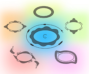

1. Introduction
Minor planets, like small moons and asteroids, are found to have regolith deposits on their surfaces, which vary in depth from a few metres on the asteroid Itokawa (Barnouin-Jha et al. Reference Barnouin-Jha, Cheng, Mukai, Abe, Hirata, Nakamura, Gaskell, Saito and Clark2008) – see figure 1 – to several tens of metres on the asteroid Eros (Cheng Reference Cheng2002; Murdoch et al. Reference Murdoch, Sanchez, Schwartz and Miyamoto2015). These regolith deposits, which are composed of unconsolidated granular material, can move on the surface of the body and their dynamics are affected by the gravity, rotation and surface topography of the body, as well as the presence of neighbouring bodies. For example, Eros is found to have freshly-exposed materials on its steep surfaces, which are believed to have resulted from granular avalanches (Veverka et al. Reference Veverka2000). Indeed, the lack of smaller craters on Eros, in spite of the presence of a sufficient number of small potential impactors, suggests that these craters were erased by regolith movement arising from seismic shaking post impact. Recently, in the context of resurfacing of Mars’ moon Phobos, Ballouz et al. (Reference Ballouz, Baresi, Crites, Kawakatsu and Fujimoto2019) demonstrated that a granular flow could be driven by even the gentle perturbations from the orbital eccentricity of the body. The primary mechanism for the accumulation of surface regolith is thought to be the agglomeration of impact ejecta. Another possibility is thermal fragmentation, which arises from a diurnal temperature variation that can break rocks faster than micro-impacts (Delbo et al. Reference Delbo, Libourel, Wilkerson, Murdoch, Michel, Ramesh, Ganino, Verati and Marchi2014).
Image of asteroid 25143 Itokawa, obtained by the Japanese Space Exploration Agency (JAXA) spacecraft Hayabusa 1 in 2005. Distinct regions of small and large grains are observed in the image on either side of the white line. Source: JAXA Digital Archives.

Dynamics of grains on and in the vicinity of planetary objects is generally interpreted from investigations into the motion of a particle in a complex gravitational environment. Thus, Dobrovolskis & Burns (Reference Dobrovolskis and Burns1980) studied ejecta from craters on Phobos, Deimos and Amalthea by employing the restricted three-body model (Murray & Dermott Reference Murray and Dermott1999, Chap. 3). They derived zero velocity curves to determine the escape conditions for ejecta. They also noted the anisotropy induced in the distribution of escape velocities arising from the rotation of the parent body. Scheeres (Reference Scheeres2015) studied conditions for initiation of landslides and the fate of the disturbed regolith on a rigid spheroidal asteroid employing local estimates of the forces at a point on the surface. By comparing the surface slope with the frictional angle of repose of the grains, the surface failure was shown to initiate before surface mass shedding, i.e. grains lost contact with the surface. This was followed by a similar study on the fate of cohesive regolith on fast-spinning asteroids (Sanchez & Scheeres Reference Sanchez and Scheeres2020). However, the dynamics of the moving regolith was not considered. Scheeres et al. (Reference Scheeres2016, Reference Scheeres, Van wal, Olikara and Baresi2019) studied the dynamical environment of the asteroids Bennu and Phobos using high-resolution shape models and derived the surface slope, lift-off speed, equilibrium points and Roche lobe. Recently, Yu et al. (Reference Yu, Michel, Hirabayashi, Schwartz, Zhang, Richardson and Liu2018, Reference Yu, Michel, Hirabayashi and Richardson2019) investigated mass shedding from the fast-spinning asteroid Didymos by analysing the motion of a particle on its surface. In spite of this rich body of work, a continuum analysis of granular flows in an extraterrestrial environment is uncommon. An exception is the work by Kokelaar et al. (Reference Kokelaar, Bahia, Joy, Viroulet and Gray2017) on lunar mass-wasting processes, which used methods of avalanche dynamics (Savage & Hutter Reference Savage and Hutter1989; Pudasaini & Hutter Reference Pudasaini and Hutter2007) that were developed for terrestrial flows. They showed that the morphology of lunar and terrestrial flows is the same as gravity scales out of the equations. However, gravity will not scale out if the avalanche occurs on a small, rotating, irregular central body, like an asteroid. This is because the length scale of a lunar avalanche is small compared with the size of the Moon, so that gravity is nearly constant along the length of the flow and, moreover, surface gravity is sufficiently large to suppress rotational effects. In contrast, on rotating small bodies, terms arising from the rotational motion of the body, e.g. centripetal and Coriolis accelerations, are of the same order as the surface gravity of the body. Additionally, if the body is irregular then, because the run-out length of avalanches may be comparable to the size of the body, gravity may vary significantly along the flow. Both of these aspects will prevent gravity from scaling out in such systems.
The study of the dynamics of regolith motion on the surface of small planetary bodies is made difficult by the complex topography, three-dimensional (3-D) rotation and non-trivial gravitational field of the body. Models of geophysical flows on the Earth do account for its topography and rotation, but the effects of these aspects are much more pronounced on small bodies like minor planets. Unlike the Earth, where gravity is normal to the surface and approximately constant everywhere, the gravity field on, say, an asteroid may also have a component in the tangential direction that can vary significantly over the surface of the body. Moreover, on small bodies, the magnitude of gravitational acceleration is of the order of  $\textrm {mm}\ \textrm {s}^{-2}$, e.g. the surface acceleration on the asteroid Eros is approximately
 $2\ \textrm {mm}\ \textrm {s}^{-2}$. Then, in contrast to the Earth whose rotation period is 24 h, small bodies can rotate much faster, with some having rotation periods as short as 2 h. Finally, the surface of small bodies is generally much more curved than that of the Earth. Faster rotation and higher curvature significantly reduce the basal pressure in surface flows which, in turn, lowers the frictional resistance to the flow; cf. § 2.5. At the same time, the presence of tangential components of a non-normal gravity and centrifugal acceleration assist surface granular flow. Thus, in contrast to the Earth, the run-out length of avalanches on small planetary bodies may be comparable to the size of the body, and this is indeed observed; cf. § 4. Under these circumstances, the global topography and rotation of the body may significantly affect the surface regolith motion. These aspects have not been included in previous studies.
Here, we take the first step towards studying regolith motion on an irregular, self-gravitating and rotating object. To this end, we investigate shallow granular flow over the surface of a rotating and self-gravitating two-dimensional (2-D) ellipse; figure 2 shows a schematic, the details of which are discussed in a later section. Our simple 2-D system includes the new processes that will influence regolith flow on a small body in space, viz. a varying gravity field, rotation of the central body and a changing surface topography. Indeed, we will observe several novel features in the flow even in the present 2-D framework. Because the setup is 2-D, it may not be possible to compare our results directly with asteroids, with the main reason being the difference in the gravity field at the circumference of a 2-D lamina and the gravity at the equator of a 3-D body. However, we do note that, in spite of the simple setting of our system, it is reminiscent of the equatorial flow of grains on a rotating small body in space.
Schematic of our system consisting of an elliptical central body with a layer of regolith of depth  $H$. Also shown are the elliptic coordinates
 $\mu$ and
 $\nu$, the rotation rate
 $\varOmega$ of the central body, the Cartesian coordinates
 $x$ and
 $y$, the linear eccentricity
 $a$, and the semi-major axes of length
 $a_1$ and
 $a_2$. We also indicate the flow directions normal
 $(u_1)$ and tangential
 $(u_2)$ to the surface. See § 2.3 for details.

The necessary governing equations for our system are obtained by an extension of avalanche dynamics (Savage & Hutter Reference Savage and Hutter1989; Gray, Wieland & Hutter Reference Gray, Wieland and Hutter1999), which is employed to model shallow granular flows on Earth. We then investigate the final deposits of regolith over the elliptical central body for different initial conditions, internal friction angles and rotation rates. We will also identify regimes of rotation rates corresponding to the manner in which the regolith moves and possibly sheds mass. The friction angles characterizing the regolith are kept within the range of  $0^{\circ }\text {--}30^{\circ }$, which allows us to explore many possible dynamical regimes. This range of friction is not unnatural, keeping in mind the fluidisation of the regolith caused by impact-induced seismic shaking (Krohn et al. Reference Krohn2014; Murdoch et al. Reference Murdoch, Sanchez, Schwartz and Miyamoto2015), and also the very low confining pressure on small planetary bodies owing to their inordinately small surface gravity (Sharma Reference Sharma2017, § 2.10), both of which may reduce the friction in the system. We then briefly study the flow of a regolith made up of a mixture of two differently sized grains. As in terrestrial avalanches, we find that big and small grains occupy, respectively, the top and bottom of the bumps formed on the surface of the central body. This outcome is consistent with the manner in which regolith is distributed on Itokawa in figure 1; see also Miyamoto et al. (Reference Miyamoto2007). Finally, given the obvious difficulty in creating experiments for our system, we perform discrete element (DE) simulations of shallow granular flow on the surface of a rotating ellipse and compare their results with our theoretical predictions. We observe a reasonably good agreement. We note that DE simulations for terrestrial landslides and avalanches have been performed previously by many researchers, e.g. Cleary (Reference Cleary2007), Liu & Koyi (Reference Liu and Koyi2013). However, similar studies on small rotating, aspherical, extra-terrestrial bodies are not available.
The paper is organized as follows: § 2 develops our mathematical model by first describing the geometry and the associated coordinate system. This is followed by a detailed derivation of the governing balance laws. At the end of the section, we arrive at the depth-averaged equations for shallow granular flow on the surface of a rotating and gravitating elliptical body. In § 3, we discuss the range of possible motions of the regolith. Conditions for grain migration and shedding are studied, and various regimes are identified depending upon the dynamics of the moving regolith. Subsequently, we discuss the results of our numerical simulation in § 4. We briefly investigate flow of a regolith composed of two different-sized grains in § 5. Finally, § 6 compares the theoretical predictions with the output of the DE simulations.
2. Shallow granular flow on a rotating and gravitating ellipse
2.1. Model
As mentioned, as the first step, we limit ourselves to two dimensions. Figure 2 shows a schematic of our system. We model the small object in space as a rigid ellipse, which is rotating at the rate  $\varOmega$ about an axis
 $\hat {\boldsymbol {k}}$ perpendicular to its plane and passing through the centre of the ellipse. The ellipse has semi-major axes of lengths
 $a_1$ and
 $a_2$ and its foci lie at a distance
 $a$ from the origin. The regolith is represented by a shallow layer of grains that moves on the surface of the ellipse. We note that the boundary of a 2-D body is, strictly speaking, a curve and not a surface. However, as this mathematical distinction will not affect our analysis, we will continue to refer to the boundary of the body as a ‘surface’.
2.2. Governing equations
We model the regolith motion as the flow of a shallow layer of dry, cohesionless grains. For simplicity, we take the flow to be incompressible. The governing equations are then obtained by an appropriate extension of the manner in which avalanche flows are studied (Gray et al. Reference Gray, Wieland and Hutter1999; Gray, Tai & Noelle Reference Gray, Tai and Noelle2003). The conservation of mass and linear momentum for a flow over the surface of a rotating central body in a coordinate frame affixed to the body are, respectively,
 \begin{equation} \boldsymbol{\nabla}\boldsymbol{\cdot}\boldsymbol{u}=0 \end{equation}
and
 \begin{equation} \rho \frac{\text{d}\boldsymbol{u}}{\text{d} t}={-}\boldsymbol{\nabla} \boldsymbol{\cdot}\boldsymbol{\mathsf{P}}+\rho\boldsymbol{b}-2\rho\boldsymbol{\varOmega}\times\boldsymbol{u},\end{equation}
where  $t$ is the time,
 $\boldsymbol {u}$ is the flow velocity,
 $\rho$ is the density of the flow,
 $\boldsymbol {\nabla }\boldsymbol {\cdot }(.)$ is the divergence operation,
 $\boldsymbol{\mathsf{P}}$ is the pressure tensor,
 $\boldsymbol {\varOmega }=\varOmega \hat {\boldsymbol {k}}$ is the rotation rate of the central body, and
 \begin{equation} \boldsymbol{b}=\boldsymbol{b_0}-\boldsymbol{\varOmega}\boldsymbol{\times}(\boldsymbol{\varOmega}\times{\boldsymbol{r}})\end{equation}
is the effective gravitational acceleration at location  $\boldsymbol {r}$, with
 $\boldsymbol {b_0}$ being the external gravity field of the central body.
The gravitational field at the boundary of a homogeneous ellipse may be obtained from the closed form formula for an ellipsoid (Sharma Reference Sharma2017, (3.22)) in the limit of the size of the semi-major axis along  $\hat {\boldsymbol {e}}_3$ tending to zero; we find
 \begin{equation} \boldsymbol{b_0}={-}\frac{3{\rm \pi} e}{2}\rho_E G \boldsymbol{\mathsf{A}}\boldsymbol{\cdot}\frac{\boldsymbol{r}}{a}, \end{equation}
where  $G$ is the universal gravitational constant,
 $e$ and
 $\rho _E$ are, respectively, the eccentricity and the density (mass per unit area) of the elliptical central body, and
 $\boldsymbol{\mathsf{A}}$ is a gravitational shape tensor that captures the effect of the shape of the body on its surface gravity field. In the principal axes coordinate system of the elliptical body,
 ${\boldsymbol{\mathsf{A}}}$ is diagonal, and may be expressed as
 \begin{equation} {\boldsymbol{\mathsf{A}}} = A_1\hat{\boldsymbol{e}}_1\otimes\hat{\boldsymbol{e}}_1+A_2\hat{\boldsymbol{e}}_2\otimes\hat{\boldsymbol{e}}_2, \end{equation}
with
 \begin{equation} A_1 = {2\gamma}\left(K[s] - E[s]\right)/({1-\gamma^2}) \end{equation}
and
 \begin{equation} A_2 = {2\gamma}(E[s]/\gamma^2 -K[s])/({1-\gamma^2}), \end{equation}
where  $\gamma = a_2/a_1$ is the axes ratio of the ellipse, and
 $K[s]$ and
 $E[s]$ are the complete elliptic integrals of the first and second kind, respectively, in terms of the parameter
 $s = \sqrt {1-\gamma ^2}$ (Abramowitz & Stegun Reference Abramowitz and Stegun1965, p. 587). Finally, combining (2.3) and (2.4), and setting
 $\boldsymbol {\varOmega }=\varOmega \hat {\boldsymbol {k}}$, we find the effective gravitational acceleration to be
 \begin{equation} \boldsymbol{b}= \left(-\frac{3{\rm \pi} e}{2a}\rho_E G \boldsymbol{\mathsf{A}} + \varOmega^2{\boldsymbol{\mathsf{1}}}\right)\boldsymbol{\cdot}{\boldsymbol{r}}, \end{equation}
where  ${\boldsymbol{\mathsf{1}}}$ is the identity tensor. Note that, in obtaining the above equation, we have approximated the external gravity field of a body in (2.3) by its surface gravity field, which is acceptable for shallow granular flows and is also consistent with the depth averaging that will follow.
The boundary conditions follow the usual pattern of the flows in earlier work (Gray et al. Reference Gray, Wieland and Hutter1999; Pudasaini & Hutter Reference Pudasaini and Hutter2003). The top of the flow is a free surface. At the bottom of the flow, we impose the no penetration condition. Further, the basal shear and normal tractions are related by a local version of Coulomb's law for dry friction as
 \begin{equation}
\hat{\boldsymbol{n}}^b\boldsymbol{\cdot}
\boldsymbol{\mathsf{P}} -
(\hat{\boldsymbol{n}}^b\boldsymbol{\cdot}\boldsymbol{\mathsf{P}}
\boldsymbol{\cdot}
\hat{\boldsymbol{n}}^b)\hat{\boldsymbol{n}}^b =
\hat{\boldsymbol{n}}^b\boldsymbol{\cdot}
\boldsymbol{\mathsf{P}}\boldsymbol{\cdot}
({\boldsymbol{\mathsf{1}}}
-\hat{\boldsymbol{n}}^b\otimes
\hat{\boldsymbol{n}}^b) ={-}\left(
\frac{\boldsymbol{u_{s}}}{|\boldsymbol{u_{s}}|}
\right)(\hat{\boldsymbol{n}}^b\boldsymbol{\cdot}\boldsymbol{\mathsf{P}}\boldsymbol{\cdot}
\hat{\boldsymbol{n}}^b)\tan\delta,\end{equation}
where  $\hat {\boldsymbol {n}}^b$ is the normal to the surface of the central body,
 $\boldsymbol {u}_s$ is the velocity of the grains at the surface of the body and
 $\tan \delta$ is the friction coefficient between the regolith and the surface of the central body. More details may be found in Gaurav (Reference Gaurav2020).
Later, we will be confronted by situations wherein an initially static regolith becomes mobile, or vice versa. To capture this aspect we need to include a basal yield criterion, which is obtained by emulating Coulomb's friction law again as
 \begin{equation}
|\hat{\boldsymbol{n}}^b\boldsymbol{\cdot}
\boldsymbol{\mathsf{P}}\boldsymbol{\cdot}
({\boldsymbol{\mathsf{1}}}
-\hat{\boldsymbol{n}}^b\otimes
\hat{\boldsymbol{n}}^b)| \leqslant
|\hat{\boldsymbol{n}}^b\boldsymbol{\cdot}\boldsymbol{\mathsf{P}}\boldsymbol{\cdot}
\hat{\boldsymbol{n}}^b|\tan\delta;
\end{equation}
thus, grains will begin slipping over the body when the shear traction at the base of the regolith cannot be sustained by the maximum basal frictional resistance that can be mobilized. At the same time, moving regolith near the surface of the body will stop when its velocity drops to zero and the shear and normal tractions at the base satisfy (2.8).
2.3. Elliptic coordinate system
The geometry of the system suggests the use of elliptic coordinates. Elliptic coordinates are generally represented by ( $\mu ,\nu$), and describe families of confocal ellipses and hyperbolae. Curves of constant
 $\mu$ represent ellipses given by
 $x^2/{a^2 \cosh ^2{\mu }}+y^2/{a^2 \sinh ^2{\mu }}=1$, whereas curves of constant
 $\nu$ yield the hyperbolae
 $x^2/{a^2 \cos ^2{\nu }}-{y^2}/{a^2 \sin ^2{\nu }}=1$, where
 $a$ is the distance of the foci from the origin, and is also called the linear eccentricity. Figure 3 plots several of these confocal ellipses and hyperbolae to show how an elliptic coordinate system is generated.
Elliptic coordinate system where curves of constant  $\mu$ (red) and
 $\nu$ (green) form confocal ellipses and confocal hyperbolae, respectively. The ellipse corresponding to
 $\mu = 0.4$ is highlighted for future reference.

An ellipse is defined completely by fixing  $a$ and the coordinate
 $\mu$. The coordinate
 $\nu$ then locates a point along the surface of the ellipse. Note that
 $a$ sets the size of the ellipse, while
 $\mu$ defines its shape in terms of its eccentricity
 $e$ and axes ratio
 $\gamma = a_2/a_1$, and we record the following formulae for future reference as
 \begin{equation} e = \text{sech}\,\mu,\quad \gamma = \tanh\mu, \quad a_1 = a \cosh\mu \quad \text{and} \quad a_2 = a \sinh\mu. \end{equation}
Finally, the transformation from elliptic coordinates to the usual Cartesian coordinates  $(x, y)$ may be done through the relations
 \begin{equation} x=a\cosh{\mu}\cos{\nu} \quad \text{and} \quad y=a\sinh{\mu}\sin{\nu}. \end{equation}
Let  be a position vector with the unit vectors
 and
 oriented along the major and minor axes, respectively, of the ellipse. The natural covariant basis vectors associated with the families of confocal ellipses and hyperbolae described above are then defined by
 $\boldsymbol {g}_i\boldsymbol {(r)}=\partial \boldsymbol {r}/\partial x^i,$ where
 $x^1 = \mu$ and
 $x^2 = \nu$ are the corresponding contravariant coordinates (Ogden Reference Ogden1997, p. 57). This provides
 \begin{equation} \mathbf{g}_1(\boldsymbol{r})=a\sinh{\mu}\cos{\nu}\,{\hat{\boldsymbol{e}}}_1+a\cosh{\mu}\sin{\nu}\,{\hat{\boldsymbol{e}}}_2 \end{equation}
and
 \begin{equation} {\boldsymbol{g}}_2(\boldsymbol{r})={-}a\cosh{\mu}\sin{\nu}\,{\hat{\boldsymbol{e}}}_1+ a\sinh{\mu}\cos{\nu}\,{\hat{\boldsymbol{e}}}_2. \end{equation}
Because  $g_{12}=g_{21}= \boldsymbol {g}_1\boldsymbol {\cdot }\boldsymbol {g}_2=0$, the natural basis vectors are orthogonal. However, these
 $\boldsymbol {g}_i$ are not unit vectors, as
 \begin{equation} \boldsymbol{g}_1\boldsymbol{\cdot}\boldsymbol{g}_1=\boldsymbol{g}_2\boldsymbol{\cdot}\boldsymbol{g}_2 := g_{11}=g_{22}=g := a^2(\sinh^2{\mu}+\sin^2{\nu}).\end{equation}
The  $g_{ij}$ above define the covariant components of the metric tensor, i.e. components with respect to the contravariant natural basis vectors
 $\boldsymbol {g}^i(\boldsymbol {r})= \boldsymbol {g}_i(\boldsymbol {r})/g$. Here
 $g$ relates to the components of the metric tensor associated with the elliptical coordinate system and should not be confused with the gravity field of the ellipse, which is denoted by
 $\boldsymbol {b_0}$ in (2.4).
The Christoffel symbols  $\varGamma ^k_{ij}(\boldsymbol {r}):={\partial \boldsymbol {g}_i}/{\partial x^j}\boldsymbol {\cdot }\boldsymbol {g}^k(\boldsymbol {r})$ may now be computed to obtain the non-zero components as
 \begin{equation} \left. \begin{gathered} \varGamma^{1}_{11}=\alpha/g; \quad \varGamma^1_{12}=\varGamma^1_{21}=\beta/g;\quad \varGamma^1_{22} ={-}\alpha/g;\\ \varGamma^2_{11}={-}\beta/g;\quad \varGamma^2_{12}=\varGamma^2_{21}=\alpha/g;\quad \varGamma^2_{22}=\beta/g; \end{gathered}\right\} \end{equation}
where
 \begin{equation} \alpha=a^2\cosh{\mu}\sinh{\mu} \quad \text{and}\quad \beta=a^2\cos{\nu}\sin{\nu}, \end{equation}
while the remaining  $\varGamma ^k_{ij}$ are zero. These Christoffel symbols may now be used to compute the gradient and divergence of various vector and tensor fields in elliptic coordinates (Ogden Reference Ogden1997, pp. 58–60). Using these results and recalling that
 $x^1 = \mu$ and
 $x^2 = \nu$, we may now express (2.1) and (2.2) in elliptic coordinates as
 \begin{equation} \frac{\partial u_{1}}{\partial \mu}+\frac{\partial u_{2}}{\partial \nu}+\frac{\alpha u_{1}}{{g}}+\frac{\beta u_{2}}{{g}}=0, \end{equation}
 \begin{align} &\rho \left[\sqrt{g}\frac{\partial u_1}{\partial t}+\frac{1}{g}\left\{\sqrt{g}u_1\frac{\partial (\sqrt{g} u_1)}{\partial \mu}+\sqrt{g}u_2\frac{\partial (\sqrt{g} u_1)}{\partial \nu}-\alpha(u_1^2+u_2^2)\right\}\right] \nonumber\\ &\quad =\rho\sqrt{g} (b_1+2 \varOmega u_2) - \frac{1}{g}\left\{\frac{\partial (gP_{11})}{\partial \mu}-\alpha(P_{11}+P_{22}) +\frac{\partial (gP_{12})}{\partial \nu}\right\} \end{align}
and
 \begin{align} &\rho \left[\sqrt{g}\frac{\partial u_{2}}{\partial t}+\frac{1}{g}\left\{\sqrt{g}u_{1} \frac{\partial (\sqrt{g} u_{2})}{\partial \mu} + \sqrt{g}u_{2} \frac{\partial (\sqrt{g} u_{2})}{\partial \nu}-\beta (u_{1}^{2}+u_{2}^{2})\right\}\right]\nonumber\\ &\quad = \rho\sqrt{g} (b_{2} - 2\varOmega u_{1}) -\frac{1}{g}\left\{\frac{\partial (gP_{12})}{\partial \mu}-\beta(P_{11}+P_{22}) +\frac{\partial (gP_{22})}{\partial \nu}\right\}. \end{align}
We now take the free surface of the flow to be given by  $F^{s}(\boldsymbol {r},t)\!=\!\mu -\{\mu _E+h(\nu ,t)\}\!=\!0$, where
 $\mu _E+h(\nu ,t)$ is the value of
 $\mu$ at the free surface at a given location
 $\nu$ on the elliptical central body described by
 $\mu =\mu _E$. The kinematic and kinetic boundary conditions at the free surface of the flow now become, respectively,
 \begin{equation} u_{1}(h,\nu,t)-\frac{\partial h(\nu,t)}{\partial \nu}u_{2} = \sqrt{g}\,\frac{\partial h(\nu,t)}{\partial t}, \end{equation}
and
 \begin{equation} P_{11}(h,\nu,t)=\frac{\partial h(\nu,t)}{\partial \nu}P_{12}(h,\nu,t)\quad \text{and} \quad P_{21}(h,\nu,t) =\frac{\partial h(\nu,t)}{\partial \nu}P_{22}(h,\nu,t). \end{equation}
Similarly, the boundary conditions at the bottom surface of the flow, which coincides with the surface of the central body, reduce to
 \begin{equation} u_{1}(0,\nu,t) = 0 \end{equation}
and
 \begin{equation} P_{12}(0,\nu,t) ={-}\text{sgn}\{u_2(0,\nu,t)\}P_{11}(0,\nu,t)\tan \delta ,\end{equation}
where ‘sgn’ is the signum function. Finally, we emphasize that  $h$ is not the vertical extent of the granular flow. Indeed, the location
 $H$ of the free surface of the flow at any
 $\nu$ for small values of
 $h$ is, in fact,
 \begin{equation} H(\nu,t) = \sqrt{g(\mu_E,\nu)}\,h(\nu,t)+{O}(h^2). \end{equation}
2.4. Non-dimensionalisation
We now follow Savage & Hutter (Reference Savage and Hutter1989) and non-dimensionalise our equations. This will allow us to identify and then ignore small terms, thereby simplifying the mathematical model. We first introduce  $\tilde {\mu }=\mu -\mu _E$ and
 $\varepsilon =H_0/a$, where we recall that
 $\mu =\mu _E$ represents the elliptical central body upon which the regolith flows,
 $H_0$ is a measure of the vertical extent of the flow and
 $\varepsilon \ll 1$ estimates the shallowness of the flow. We then define non-dimensional variables, identified by the superscript ‘
 $*$’, as follows
 \begin{gather} \tilde{\mu}=\varepsilon \mu^{*};\quad (u_1,u_2)=\sqrt{ba}(\varepsilon u_1^*, u_2^*);\quad t=(\sqrt{{a}/{b}}) t^{*}; \end{gather}
 \begin{gather}(P_{11},P_{22},P_{12})=\rho b H_0(P_{11}^*,P^{*}_{22},\tan\delta P_{12}^*); \end{gather}
 \begin{gather}b_1=bb_1^*,\quad b_2=bb_2^*;\quad g=a^{2} g^{*};\quad \alpha=a^2\alpha^*;\quad \beta=a^2 \beta^*; \end{gather}
where  and
 are effective gravitational accelerations in the normal and tangential direction, respectively, and
 \begin{equation} b = 3{\rm \pi} e\rho_EG/2 \end{equation}
is a scaling motivated by the right-hand side of (2.6).
With this, we non-dimensionalise (2.15)–(2.17) to obtain, respectively,
 \begin{equation} \frac{\partial u_{1}}{\partial \mu}+\frac{\partial u_{2}}{\partial \nu}+\varepsilon\frac{\alpha u_{1}}{{g}}+\frac{\beta u_{2}}{{g}}=0,\end{equation}
 \begin{align} &\varepsilon\sqrt{g}\frac{\partial u_1}{\partial t}+\frac{1}{g}\left\{\varepsilon\sqrt{g}u_1\frac{\partial (\sqrt{g} u_1)}{\partial \mu}+\varepsilon\sqrt{g}u_2\frac{\partial (\sqrt{g} u_1)}{\partial \nu}-\alpha(\varepsilon^2u_1^2+u_2^2)\right\} \nonumber\\ &\quad =\sqrt{g} \left(b_1+2 \omega u_2\right) - \frac{1}{g}\left\{\frac{\partial (gP_{11})}{\partial \mu}-\varepsilon\alpha(P_{11}+P_{22}) +\varepsilon\tan\delta\frac{\partial (gP_{12})}{\partial \nu}\right\} \end{align}
and
 \begin{align} &\sqrt{g}\,\frac{\partial u_{2}}{\partial t}+\frac{1}{g}\left(\sqrt{g}u_{1} \frac{\partial (\sqrt{g} u_{2})}{\partial \mu} + \sqrt{g}u_{2} \frac{\partial (\sqrt{g} u_{2})}{\partial \nu}-\beta (\varepsilon^2 u_{1}^{2}+u_{2}^{2})\right) \nonumber\\ &\quad = \sqrt{g} \left(b_{2} - 2\varepsilon\omega u_{1}\right) -\frac{1}{g}\left\{\tan\delta\frac{\partial (gP_{12})}{\partial \mu}-\beta\varepsilon(P_{11}+P_{22}) +\varepsilon\frac{\partial (gP_{22})}{\partial \nu}\right\}, \end{align}
where
 \begin{equation} \omega=\varOmega\sqrt{{a}/{b}} \end{equation}
is the non-dimensional rotation rate, and the superscript ‘ $*$’ is suppressed to simplify the notation. Similarly, the non-dimensional boundary conditions at the free surface of the flow are obtained from (2.18) to be
 \begin{equation} u_{1}(h,\nu,t)-\frac{\partial h(\nu,t)}{\partial \nu}u_{2}(h,\nu,t)=\sqrt{g}\frac{\partial h(\nu,t)}{\partial t}, \end{equation}
 \begin{equation}P_{11}(h,\nu,t)=\varepsilon\frac{\partial h(\nu,t)}{\partial \nu}P_{12}(h,\nu,t)\quad \text{and}\quad P_{21}(h,\nu,t)=\varepsilon\frac{\partial h(\nu,t)}{\partial \nu}P_{22}(h,\nu,t). \end{equation}
The non-dimensional boundary conditions at the bottom surface of the flow (2.19) becomes
 \begin{equation} u_{1}(0,\nu,t) = 0 \end{equation}
and
 \begin{equation} P_{12}(0,\nu,t) ={-}\text{sgn}\{u_2(0,\nu,t)\}P_{11}(0,\nu,t). \end{equation}
In the subsequent development, we will approximate the mass conservation and momentum conservation in the normal direction, respectively, (2.23) and (2.24), to the leading order, and neglect all terms of  ${O}(\varepsilon )$ or higher. However, we will retain the
 ${O}(\varepsilon )$ terms in (2.25), i.e. in the linear momentum balance in the tangential direction, to incorporate the effects of the Coriolis force, the pressure tensor and its gradient in driving the flow in the tangential direction. This is a standard practice in the analysis of shallow flows; see, e.g. Savage & Hutter (Reference Savage and Hutter1989) and Gray et al. (Reference Gray, Wieland and Hutter1999).
We close this section by noting that when non-dimensionalising, we assumed the length scale of the flow to be  ${O}(a)$, i.e. the regolith flow takes place over a distance comparable to the size of the central body.
2.5. Depth integration
As the regolith layer is shallow, flow variations in the direction normal to the surface of the central body are expected to be smaller than those along the surface. At the same time, our main interest is in the surface transport of regolith. We, thus, depth average the governing equations along the surface normal. Depth integration of (2.23)–(2.25) is complicated by the presence of metric coefficients  $g,\alpha ,\beta$ and a complex gravity field, all of which vary with depth
 $\mu$. As the flow is shallow, we ignore this variation, which simplifies the depth integration considerably. We define the following depth-averaged quantities as
 \begin{equation} \bar{u}_ih=\int_{0}^{h} u_i \,\text{d}\mu ,\quad \bar{P}_{ij}h=\int_{0}^{h}P_{ij}\,\text{d}\mu \quad \text{and} \quad \overline{u_i^{2}}h:=\int_{0}^{h} u_i^{2}\,\text{d}\mu=\chi\bar{u}_i^2h ,\end{equation}
where we recall that in § 2.4 we had re-scaled the coordinate  $\mu$ so that it vanishes at the surface of the elliptical body and
 $\mu =h$ is the free surface of the regolith. For most flow profiles,
 $\chi \approx 1$ (Savage & Hutter Reference Savage and Hutter1989) and, for simplicity, we will set
 $\chi =1$.
At the leading order, depth averaging the continuity equation (2.23) yields
 \begin{equation} \frac{\partial (gh)}{\partial t}+\frac{\partial (\sqrt{g}\bar{u}_2h)}{\partial \nu}=0.\end{equation}
The leading-order momentum conservation in the normal direction (2.24) becomes
 \begin{equation} \frac{1}{g} \frac{\partial (gP_{11})}{\partial \mu}=\frac{\alpha u_2^2}{g} +\sqrt{g} \left(b_1+2 \omega u_2\right). \end{equation}
The normal pressure at any depth  $\mu$ may be obtained by integrating the above from the free surface
 $h(\nu )$ of the flow to a depth
 $\mu$, which invokes the following estimates
 \begin{equation} \bar{u}_2(h-\mu)=\int_{\mu}^{h} u_2 \,\text{d}\mu\quad \text{and} \quad \bar{u}^2_2(h-\mu)=\int_{\mu}^{h} u_2^2 \,\text{d}\mu, \end{equation}
and by employing the boundary condition (2.27) at the free surface of the flow. The normal pressure at the location  $\mu$ is then given by
 \begin{equation} P_{11}(\mu)={-}\psi(h-\mu), \end{equation}
where
 \begin{equation} \psi(\nu)=\frac{\alpha}{g}\bar{u}_2^2+\sqrt{g}\left(b_1+2\omega\bar{u}_2\right). \end{equation}
The form of the normal pressure  $P_{11}$ in (2.33) is different from that obtained in usual shallow flow analyses, wherein
 $\psi$ is a constant gravitational acceleration and is independent of the flow velocity. Our flow takes place over a curved and rotating body, which yields two extra terms. Thus, in (2.33b), the first term on the right is the centripetal acceleration arising from the flow taking place over the curvilinear boundary of the elliptical central body, while the last term is the Coriolis acceleration arising from the rotation of the central body. We note that shallow water theory when applied to geophysical flows (Pedlosky Reference Pedlosky1987; Dellar & Salmon Reference Dellar and Salmon2005) contains contributions from the Coriolis acceleration and topography, but suppresses the centripetal contribution as the curvature of the Earth is negligible; this will not be true for minor planets. Separately, for application to avalanches, Pudasaini & Hutter (Reference Pudasaini and Hutter2007) and Gray et al. (Reference Gray, Wieland and Hutter1999) studied granular flows over a variable topography, wherein the effects of the basal curvature and torsion on the normal pressure was incorporated but rotational effects were, of course, ignored. The system considered here, and the accompanying mathematical development, is the first to retain the full impact of both the varying topography of the underlying body and its rotation on the surface granular flow.
Next, integrating the momentum conservation in the tangential direction (2.25) across the vertical extent of the flow, while neglecting  ${O}(\varepsilon ^2)$ terms but retaining those of
 ${O}(\varepsilon )$, and applying boundary conditions (2.27) and (2.28), yields
 \begin{align} \sqrt{g}\frac{\partial (\bar{u}_{2}h)}{\partial t}+\frac{1}{g}\frac{\partial (g\bar{u}_2^2h)}{\partial \nu} -\frac{\beta}{g}(\bar{u}_2^2h) &={-}\text{sgn}(\bar{u}_2)P_{11}(0,\nu,t) \tan\delta +\sqrt{g}b_2h \dots \nonumber\\ &\quad -\varepsilon\left\{\frac{1}{g}\frac{\partial ( g\bar{P}_{22} h)}{\partial \nu} -\frac{\beta}{g}(\bar{P}_{22}+\bar{P}_{11}) h+2\sqrt{g}\omega\bar{u}_1h\right\} . \end{align}
We may eliminate  $\bar {u}_1$ that appears in the Coriolis term in the above equation – last term on the right-hand side – by using the mass balance (2.23) as follows. By multiplying (2.23) by
 $\sqrt {g}$, rearranging, integrating from
 $\mu =0$ to a depth
 $\mu$ and invoking the boundary condition (2.28), we obtain the normal velocity as
 \begin{equation} \sqrt{g}\,u_1(\mu, \nu, t) ={-}\frac{\partial }{\partial \nu}\int_0^{\mu}\sqrt{g}u_2\,\text{d}\mu. \end{equation}
The right-hand side of the above equation may be approximated in a manner similar to (2.32a,b), to find
 \begin{equation} u_1={-}\frac{1}{\sqrt{g}}\frac{\partial (\sqrt{g}\bar{u}_2)}{\partial \nu}\mu, \end{equation}
which, on depth averaging, provides
 \begin{equation} \bar{u}_1={-}\frac{1}{\sqrt{g}}\frac{\partial (\sqrt{g}\bar{u}_2)}{\partial \nu}\frac{h}{2}.\end{equation}
As of now, we have five variables  $\bar {u}_1$,
 $\bar {u}_2$,
 $h$,
 ${P}_{11}$ and
 $\bar {P}_{22}$, and only four equations (2.30) and (2.33)–(2.37). To complete the mathematical description, we need a constitutive law for the flowing granular material. This is also expected, else our predictions would be applicable to all manner of shallow regolith flows. Specifically, we require an estimate for
 ${\bar {P}}_{22}$ to use in (2.34). For this we proceed as follows.
One way to estimate  ${\bar {P}}_{22}$ in (2.34) is to invoke Earth-pressure theory (Nedderman Reference Nedderman1992, p. 34) to relate the normal and lateral normal components of the pressure tensor. By employing this, Savage & Hutter (Reference Savage and Hutter1989) were able to establish the relation
 \begin{equation} {\bar{P}}_{22} = k^\pm {\bar{P}}_{11}, \end{equation}
where  $k^\pm$ are the active/passive Earth pressure coefficients that depend on whether the stress state is passive (compressional flow,
 $\partial {\bar {u}}_2/\partial \nu < 0$) or active (elongational flow,
 $\partial {\bar {u}}_2/\partial \nu > 0$). Furthermore, Savage & Hutter (Reference Savage and Hutter1989) related
 $k^\pm$ to the internal friction angle of the granular regolith, assuming it to be a cohesionless Mohr–Coulomb material (Nedderman Reference Nedderman1992, p. 25).
By using (2.37), (2.38) and (2.33) to eliminate  ${\bar u}_1, {\bar {P}}_{22}, {\bar {P}}_{11}$ and
 $P_{11}(0, \nu , t)$ in (2.34), we obtain the final form for the momentum balance in the tangential direction as
 \begin{align} & \frac{\partial }{\partial t}\left(\sqrt{g}\bar{u}_2h\right)+\frac{1}{g}\frac{\partial }{\partial \nu}\left\{g\left(\bar{u}_2^2h-\varepsilon k \psi \frac{h^2}{2}\right)\right\}- \varepsilon\omega h^2\frac{\partial }{\partial \nu}\left(\sqrt{g}\bar{u}_2\right) \nonumber\\ &\quad =\frac{\beta}{g}(\bar{u}^2_2h) +\text{sgn}(\bar{u}_2)\psi h\tan\delta +\sqrt{g}b_2h-\varepsilon\frac{\beta}{g}(k+1)\psi \frac{h^2}{2}. \end{align}
In the above, the flux term has an extra contribution – third term on the left side – from the Coriolis acceleration, while the  $\beta /g$ term in the source term on the right arises from the surface topography. Our mathematical model is finally complete with two equations (2.30) and (2.39) for the two variables
 $h$ and
 $\bar {u}_2$. These equations constitute a hyperbolic system that we will solve numerically for several choices of initial data. We begin by discussing some general features of the motion of the regolith in our system.
3. General considerations
The governing equations obtained in the previous section will be solved numerically in § 4 for different values of the rotation rate of the central body  $\varOmega$ and the basal and internal friction angles
 $\delta$ and
 $\phi$, respectively, of the regolith. In this section, we will identify generic behaviours of the regolith that will help better understand the later results. We begin by using equations obtained in the previous section to find constraints on
 $\varOmega$ and
 $\delta$ for grain migration and shedding. In all plots henceforth, the ends of the major axis are located at
 $\nu =0$ and
 ${\rm \pi}$, while the minor axis extends from
 $\nu ={\rm \pi} /2$ to
 $3{\rm \pi} /2$.
3.1. Grain shedding
Beyond a certain rotation rate, grains in the regolith will lose contact with the surface of the body. This happens when the normal pressure (2.33a) becomes negative at the base, i.e. whenever  $P_{11}(\mu = 0) \leqslant 0$. Ignoring the possibility of re-agglomeration, we assume that grains that lose contact with the central body are shed permanently. From (2.33b), we may obtain the condition for the shedding of a stationary regolith from the surface of the body by setting the flow velocity to zero: a stationary regolith will not shed as long as
 \begin{equation} b_1<0,\end{equation}
where  $b_1$ is the normal component of the effective gravity defined in (2.6). When
 $b_1>0$, the gravitational force on a grain is unable to provide the necessary centripetal acceleration and the grain leaves the surface; see also Scheeres (Reference Scheeres2015). Using (2.6) and (2.10a,b)–(2.12), we find that
 \begin{equation} b_1 = \sinh\mu_E\cosh\mu_E\{\omega^2 - (A_1\cos^2\nu + A_2\sin^2\nu)\}/ \sqrt{\sinh^2\mu_E+\sin^2\nu}, \end{equation}
where  $\mu _E$ defines the shape of the elliptical central body – specifically, its eccentricity
 $e$ and axes ratio
 $\gamma = a_2/a_1$, cf. (2.9a–d) –
 $\nu$ is the angular location along the surface of the body, the
 $A_i$ depend only on
 $\gamma$ and are given by (2.5), and
 $\omega$ is the non-dimensional rotation rate.
From (3.2), we immediately see that at any surface location  $\nu$,
 $b_1$ vanishes when
 $\omega$ equals
 ${(A_1\cos ^2\nu + A_2\sin ^2\nu )}^{1/2}$, a value that depends only on the axes ratio of the elliptical body and not its size
 $a$. Of course, given (2.26), the corresponding dimensional rotation rate
 $\varOmega$ will depend on the size of the body. We may now define the shedding rotation rate
 $\omega _{sh}$ as the rotation rate at which
 $b_1$ first becomes positive anywhere on the surface of the body, so that mass shedding is initiated. Because
 $A_1 \leqslant A_2$, we must have
 \begin{equation} \omega_{sh} = \sqrt{A_1}. \end{equation}
Thus, mass is first lost from the ends of the major axis of the central body when  $\omega$ equals
 $\omega _{sh}$. The expression for
 $\omega _{sh}$ has a structure similar to the formula obtained for the rotation rate of Maclaurin spheroids in the limit of the third axis going to zero (Chandrasekhar Reference Chandrasekhar1969; Sharma, Jenkins & Burns Reference Sharma, Jenkins and Burns2009), although we do note that in that limit, a Maclaurin spheroid will flatten into a circle and not an ellipse. Similar connections with equilibrated shapes of rotating fluids, in the context of particle motion on rotating and gravitating ellipsoids, were established by Guibout & Scheeres (Reference Guibout and Scheeres2003).
Figure 4(a) shows curves which trace the variation of  $b_1$ at the ends of the major and minor axes with the rotation rate
 $\omega$ for an elliptical central body with
 $\mu _E = 0.4$, for which
 $\omega _{sh} = 1.06$. We observe three regions. In region
 $\mathrm {I}$, the stationary regolith does not lose grains because the gravity of the central body is stronger than the centrifugal force in a direction normal to its surface and hence
 $b_1$ is negative. As
 $\omega$ increases, the latter exceeds the former for the first time at the ends of the major axis, which is indicated by
 $b_1$ vanishing there when
 $\omega = \omega _{sh}$. At this time, a stationary grain at
 $\nu = 0$ and
 $\nu = {\rm \pi}$ loses contact with the surface and is shed. As
 $\omega$ is raised beyond
 $\omega _{sh}$, grains begin to shed from proportionately expanding zones centred around
 $\nu = 0$ and
 $\nu = {\rm \pi}$. This is represented by region
 $\mathrm {II}$, in which
 $b_1$ at and around the ends of the major axis is now positive. When
 $\omega = \sqrt {A_2} \approx 2.21$, mass shedding initiates even from the ends of the minor axis. Thus, in region
 $\mathrm {III}$, mass is being lost from all points on the surface of the body and
 $b_1>0$ at the minor axis.
(a) Variation with the non-dimensional rotation rate  $\omega$ of the scaled effective normal gravity
 $b_1$ at the ends of the major (
 $\nu =0 \ \mbox {and} \ {\rm \pi}$, blue curve) and minor (
 $\nu ={\rm \pi} /2 \ \mbox {and} \ 3{\rm \pi} /2$, orange curve) axes of an elliptical body with
 $\mu _E=0.4$
 $(e \approx 0.93, \gamma \approx 0.38)$. Here,
 $b_1$ vanishes first at
 $\omega _{sh}= 1.06$. (b) The shedding landscape for stationary regolith on an elliptical body in its shape (
 $\gamma$)–rotation (
 $\omega$) parameter space. The total area of the ellipse is kept constant as
 $\gamma$ is changed.

In figure 4(b), we depict the shedding landscape for stationary regolith on a rotating and gravitating elliptical body in its shape ( $\gamma$)–rotation (
 $\omega$) parameter space. We see how regions
 $\mathrm {I}\text{--}\mathrm {III}$ defined in figure 4(a) evolve with the axes ratio
 $\gamma$. In particular, as
 $\gamma \rightarrow 1$, the geometry of the body becomes more circular. Thus, the rotation rates at which mass shedding initiates from the ends of the minor and major axes merge to the same value for a circular body (
 $\gamma = 1$).
Before closing this section, we emphasize that the above analysis is restricted to stationary regolith. Mass shedding in moving regolith may start at  $\omega$ lower or higher than
 $\omega _{sh}$ depending upon the direction of granular flow, and this is discussed in § 3.3.
3.2. Grain migration
Grains may migrate towards the minor or major axis of the elliptical central body depending upon its rotation rate. This is expected because, in the absence of rotation, grains would prefer to be at the ends of the minor axis where the gravitational potential is minimum. However, at high rotation rates, centrifugal effects shift the location of the minimum of the total potential to the ends of the major axis. We now investigate this process.
In a depth-averaged description, regolith motion will be initiated when the basal yield criterion (2.8) is violated. To test this, we require an estimate of the shear stress at the base of a static regolith. This may be obtained as follows. We set the velocity terms to zero in the tangential balance of momentum (2.25) to find
 \begin{equation} \sqrt{g} \, b_{2} -\frac{1}{g}\left\{\tan\delta\frac{\partial }{\partial \mu}\left(gP_{12}\right)-\beta\varepsilon\left(P_{11}+P_{22}\right) +\varepsilon\frac{\partial }{\partial \nu}\left(gP_{22}\right)\right\} =0. \end{equation}
Depth averaging the above, using (2.38) and employing the boundary condition at the top of the flow (2.27) provides the shear stress at the base ( $\mu = 0$) of a static regolith as
 \begin{equation} \tan\delta P_{12}(0, \nu) ={-} \sqrt{g}b_2h+\frac{\varepsilon}{2g}\left\{- \frac{\partial }{\partial \nu}(g \psi h^2) k^{{\pm}}+ \beta(k^{{\pm}}+1)\psi h^2\right\},\end{equation}
where  $b_2$ and
 $\psi$ depend on the rotation rate of the central body
 $\omega$; cf. (2.6) and (2.33b), respectively. Combining the preceding equation with the basal yield criterion (2.8), we find that regolith motion will not commence as long as the following inequality holds

The left-hand side of (3.6) is dominated by the effective tangential gravity  $b_2$, as the other terms are of
 ${O}(\varepsilon )$. Employing (2.6) and (2.10a,b)–(2.12), we compute
 \begin{equation} b_2 = \sin\nu\cos\nu\{-\omega^2 + (A_1\cosh^2\mu_E - A_2\sinh^2\mu_E)\}/ \sqrt{\sinh^2\mu_E+\sin^2\nu}. \end{equation}
As for  $b_1$ in (3.2), given a non-dimensional rotation rate
 $\omega$,
 $b_2$ depends only on the shape of the elliptical body, as defined by
 $\mu _E$, and not its size. Furthermore,
 $b_2$ vanishes whenever
 $\omega$ equals
 \begin{equation} \omega_{th} := (A_1\cosh^2\mu_E - A_2\sinh^2\mu_E)^{1/2}, \end{equation}
which defines the threshold rotation rate. From (3.7) and (3.8), we see that when  $\sin 2\nu > 0$,
 $b_2$ is positive (i.e. directed along increasing
 $\nu$) or negative (i.e. pointed towards decreasing
 $\nu$) depending upon whether
 $\omega$ is less than or greater than
 $\omega _{th}$, respectively. When
 $\sin 2\nu <0$, the sign of
 $b_2$ reverses. Thus, in the absence of basal friction (
 $\delta = 0^{\circ }$), grains tend to migrate towards the ends of a smooth minor/major axis of the elliptical central body when
 $\omega \lessgtr \omega _{th}$. Furthermore, regolith can only be stationary on a smooth body if it rotates at exactly
 $\omega _{th}$. We also observe that
 $\omega _{th}$ is independent of the angular location
 $\nu$ on the central body and its size, so that regolith on a smooth surface of the body is mobilized simultaneously everywhere when
 $\omega \neq \omega _{th}$. Consequently, the dimensional threshold rotation rate
 $\varOmega _{th}$ is also unaffected by
 $\nu$, but not by the size of the body; cf. (2.26). In this context, we again recall the work of Guibout & Scheeres (Reference Guibout and Scheeres2003). They showed that the tangential acceleration on the surface of a rotating and gravitating ellipsoid only vanishes for some axes ratios, so that
 $\omega _{th}$ may not exist for all 3-D ellipsoidal bodies. This indicates an important distinction between 2-D and 3-D systems. Finally, similar to
 $\omega _{sh}$ above, we note that the formula (3.8) for
 $\omega _{th}$ matches the expression that we obtain for the rotation rate of the fluid Jacobi ellipsoid (Chandrasekhar Reference Chandrasekhar1969; Sharma et al. Reference Sharma, Jenkins and Burns2009) when the third axis is shrunk to zero.
Figure 5(a) shows the variation of  $b_2$ with the rotation rate
 $\omega$ at various angular locations
 $\nu$ in the first quadrant of an elliptical central body with
 $\mu _E = 0.4$. As expected from the above discussion, the curve for each
 $\nu$ crosses the abscissa at the same point when
 $\omega = \omega _{th}$. We observe that when
 $\mu _E = 0.4$,
 $\omega _{th}= 0.66\omega _{sh}$. In general, the threshold rotation rate is lower than the shedding rotation rate, as is also clear from comparing (3.3) and (3.8). This is consistent with the understanding that at low
 $\omega$, grains migrate to the minor axis, while shedding is first initiated only from the ends of the major axis. Thus, grains need to first switch their direction of motion, which occurs when
 $\omega = \omega _{th}$.
(a) Variation with the non-dimensional rotation rate  $\omega$ of the scaled effective tangential gravity
 $b_2$ for an elliptical central body with
 $\mu _E=0.4$
 $(e \approx 0.93, \gamma \approx 0.38)$. Several angular locations
 $\nu$ are considered and these are indicated next to their associated curves. (b) The migration landscape on a smooth (
 $\delta = 0^{\circ }$) elliptical body in its shape (
 $\gamma$)–rotation rate (
 $\omega$) parameter space. The total area of the ellipse is kept constant as
 $\gamma$ is changed.

Figure 5(b) displays the migration landscape for regolith on a smooth ( $\delta =0^\circ$), rotating and gravitating elliptical body in its shape (
 $\gamma$)–rotation rate (
 $\omega$) parameter space. The regions below and above the shedding curve
 $\omega = \omega _{sh}$ correspond to the regions
 ${\mathrm I}$ and
 $\mathrm {II}$ of figure 4(b), respectively. Region
 ${\mathrm I}$ is divided into two zones in figure 5(b) that are separated by the threshold curve
 $\omega =\omega _{th}$ at which the effective tangential gravity
 $b_2$ vanishes everywhere on the surface of the body. Below the threshold curve, grains approach the minor axis of the body, while for
 $\omega _{sh}>\omega >\omega _{th}$, grains migrate towards the major axis. Above
 $\omega _{sh}$, grains begin shedding from the major axis. Finally, in the absence of basal friction, surface regolith may remain stationary only if the
 $\gamma$ and
 $\omega$ of the body are such that they lie on the threshold curve.
Consider now the case when basal friction is present, i.e.  $\delta > 0^{\circ }$. As the right-hand side is non-zero, the inequality in (3.6), even at the leading order, will now be satisfied by a range of rotation rates
 $\omega$. Therefore, while regolith on a smooth body could be stationary only if
 $\omega = \omega _{th}$, grains can remain motionless for a range of rotation rates centred around
 $\omega _{th}$ when the surface of the body is rough. The upper and lower bounds of this range may be derived at the leading order from (3.6) to be
 \begin{equation} \omega^\pm{=}\left[\max\left\{0,\frac{\pm \omega^2_{sh}(A_1\cos^2\nu_c^\pm{+}A_2\sin^2\nu_c^\pm)d_0+\omega^2_{th}\sin{\nu_c^\pm}\cos{\nu_c^\pm}}{\pm d_0+\omega^2_{th}\sin{\nu_c^\pm}\cos{\nu_c^\pm}}\right\}\right]^{1/2}\\ \end{equation}
where  $d_0=\sinh {\mu _E}\cosh {\mu _E}\tan \delta$,
 $w_0=\{2\omega ^2_{th}-(A_1+A_2)\}/(A_2-A_1)$,
 \begin{equation} \nu_c^\pm{=}{-}\left(\frac{\pm 2d_0 + \omega_0\sqrt{4d_0^2+w_0^2-1}}{4d_0^2+w_0^2}\right) \end{equation}
and ‘ $+$’ and ‘
 $-$’ correspond to the upper and lower bounds, respectively.
When  $\delta > 0^{\circ }$, the regolith does not fail simultaneously at all points of the surface, as it does when
 $\delta =0^{\circ }$. The critical angles
 $\nu _c^\pm$ in (3.10) are the angular locations on a given central body where the regolith first gets mobilised when the rotation rate
 $\omega$ is raised above or lowered from
 $\omega _{th}$, respectively, and crosses a critical value. Figure 6 displays the variation of
 $\nu _c$ with the axes ratio
 $\gamma$ of the central body. With this understanding of
 $\nu _c$, the upper (
 $\omega ^+$) and lower (
 $\omega ^-$) bounds given by (3.9) thus represent, respectively, the least upper bound and the greatest lower bound of the range of rotation rates
 $\omega$ within which the regolith can persist in a stationary state everywhere on the elliptical central body. Therefore, when
 $\omega \rightarrow \omega ^\pm$, then grains located at
 $\nu _c^\pm$ start flowing, but remain stationary elsewhere.
Variation of the critical angle  $\nu _c$ with axes ratio
 $\gamma$ for different choices of basal friction angle
 $\delta$ that are indicated next to their associated curves. The solid (
 $\nu _c^+$) and dashed (
 $\nu _c^-$) curves correspond, respectively, to the upper (
 $\omega ^+$) and lower (
 $\omega ^-$) bounds of the range of rotation rates within which stationary regolith can persist everywhere on the surface of the central body; see main text for details.

Figure 7(a) revisits figure 5(b) but with  $\delta = 20^{\circ }$. We find that the region
 ${\mathrm {I}}$ that lies below the shedding curve
 $\omega = \omega _{sh}$ is now subdivided into three zones:
 $A$,
 $B$ and
 $C$. Owing to the presence of basal friction, elliptical bodies lying in zone
 $B$ have immobile regolith, despite non-zero values of effective tangential acceleration
 $b_2$. The upper and lower bounds of zone
 $B$ are provided by (3.9), and are depicted in figure 7(a) by, respectively, the solid (
 $\omega = \omega ^+$) and dashed (
 $\omega = \omega ^-$) red curves centred around the threshold curve
 $\omega = \omega _{th}$ (black curve). The angular locations at which grains would first become mobilized when the upper or lower bound is breached may be found by noting the corresponding critical angular location
 $\nu _c$ in figure 6. In zones
 $C$ and
 $A$, grains are mobilized from regions centred around
 $\nu = \nu _c^\pm$, which then migrate towards the ends of the minor and major axes, respectively, unless this migration is resisted by static grains surrounding the mobilized regions. As in figure 5(b), zone
 $C$ is bounded above by region
 $\mathrm {II}$ of figure 4(b). We henceforth call zones
 $A$,
 $B$ and
 $C$ as the pre-critical, critical and post-critical regimes, respectively.
Continued from figure 5(b). (a) Different types of behaviour of surface regolith for an elliptical central body with  $\mu _E=0.4$ and basal friction angle
 $\delta =20^{\circ }$. Zones
 $A$,
 $B$ and
 $C$, make up region
 ${\mathrm I}$ in figure 5(b). (b) Variation of the lower (dashed) and upper (solid) boundaries of zone
 $B$ in (a) for different basal friction angles
 $\delta$ that are indicated next to their associated curves.

Figure 7(b) repeats figure 7(a) for various choices of basal friction angle  $\delta$. We find that zone
 $B$ expands with
 $\delta$. Correspondingly, figure 6 shows that
 $\nu _c^-$ shifts towards the minor axis, while
 $\nu _c^+$ moves towards the major axis when
 $\delta$ is increased, i.e. at a higher basal friction, grains closer to the major/minor axes are the first to become mobilized when the upper/lower boundaries of region
 $B$ are crossed. We also observe that the lower boundary of zone
 $B$ vanishes when
 $\delta \gtrapprox 35^\circ$. Therefore, when the basal friction is sufficiently high, grains never migrate towards the minor axis no matter how low the rotation rate might be. Finally, the regolith remains stationary for a larger range of rotation rates with an increase in basal friction and a decrease in the eccentricity of the central body, i.e. when
 $\gamma \rightarrow 1$ . This may also be understood directly from (3.6) and (3.7). Higher basal friction augments the right-hand side while a lowering in eccentricity – i.e. raising of
 $\mu _E$ – diminishes
 $b_2$ on the left side, which allows for a broader range of
 $\omega$ to strictly satisfy the inequality (3.6).
We close this section with three remarks. First, as we saw above, for granular flow to start from rest at any point on the surface, the basal resistance must be overcome by the effective tangential gravity there, i.e. the equality must hold in (3.6). This was shown to not happen simultaneously at all points on the surface of the body when  $\delta > 0^{\circ }$; cf. (3.10) and the associated discussion. At the same time, we found in § 3.1 that there can be locations on the surface of the body from where grains will be lost. Thus, there could be regions on the surface that have moving regolith coexisting with zones where grains are stationary or are not present. Second, the foregoing discussion tacitly assumed that the free surface of the regolith is at a constant distance
 $h$ from the surface of the body, so that we could ignore its variation in (3.6). Basal pressure will be higher at larger
 $h$, which will translate to a greater basal resistance that, in turn, will affect if and how the regolith flows. Both these aspects will, as we see in later sections, add to the complexity of the motion of the regolith. Finally, the analysis so far parallels the recent work of Sanchez & Scheeres (Reference Sanchez and Scheeres2020) who included cohesion, but predicated their development on the force balance of a single boulder on a spherical body. In contrast, ours is a continuum analysis and we have not included the effect of cohesion in this work to retain focus on the flow of grains over a non-spherical body in the presence of rotation and varying gravity. The effects of cohesion may be included by a straightforward modification of the yielding condition and the basal interaction law.
3.3. Lift-off velocity
In § 3.1, we found the rotation rate  $\omega _{sh}$ beyond which a stationary regolith first begins to shed. However, a flowing regolith may lose contact with the elliptical central body at rotation rates below or above
 $\omega _{sh}$ depending upon the direction of flow. Grains are shed from the surface when the basal pressure
 $P_{11}$ becomes negative at that location. The condition that the basal pressure in the regolith flow, provided by (2.33), remains positive at any surface location
 $\nu$, limits the maximum velocity that the granular flow may attain before grains lose contact with the surface. This velocity is called the lift-off velocity
 $u_l$; see also Van wal & Scheeres (Reference Van wal and Scheeres2017).
We find from (2.33) that  $P_{11}$ becomes negative when
 $\psi >0$. The function
 $\psi$ is quadratic in velocity and vanishes when the average flow velocity
 ${\bar {u}}_2$ equals
 \begin{equation} {u}_{l}^\pm{=}\frac{-\omega g_E^{3/2} \pm(\omega ^2g_E^3 -\alpha_E b_1 g_E^{3/2})^{1/2}}{\alpha_E}, \end{equation}
where  $g_E$ and
 $\alpha _E$ are given by, respectively, (2.12) and (2.14a,b) with
 $\mu = \mu _E$, and then non-dimensionalised as per (2.21c). Now, for
 $\omega <\omega _{sh}$, the effective normal gravity
 $b_1$ is negative everywhere, so that
 $u_l^- < 0 < u_l^+$ and
 $|u_l^-| > |u_l^+|$. Therefore, even at rotation rates below the shedding rotation rate
 $\omega _{sh}$, grains will be lost from a location on the surface of the elliptical central body if the flow velocity there satisfies either
 ${\bar {u}}_2 > u_l^+$ or
 ${\bar {u}}_2 < u_l^-$. Note that the lift-off velocities are independent of basal friction, as
 $P_{11}$ does not depend on
 $\delta$.
To facilitate subsequent discussion, we propose a few definitions. Grains whose flow velocity  $\bar {u}_2$, relative to the rotating central body, is co-directional with the surface velocity (
 ) of the body are said to have prograde velocities, while those with
 $\bar {u}_2$ opposite to
 have retrograde velocities. We define the prograde (retrograde) sides of the central body as the surface regions wherein grains have prograde (retrograde) velocities. Keeping in mind the setup of figure 2, prograde and retrograde motions have, respectively, positive and negative
 ${\bar {u}}_2$. Thus, grains that are shed because
 ${\bar {u}}_2 > u_l^+$ were necessarily in prograde motion, while if mass is lost because
 ${\bar {u}}_2 < u_l^-$, then the flow was retrograde.
Figure 8 plots the variations of the lift-off velocities  $u_l^+$ and
 $u_l^-$ along the surface of an elliptical central body defined by
 $\mu _E=0.4$ for several rotation rates
 $\omega$. We confirm that
 $|u_l^-| > |u_l^+|$ at a given
 $\omega$. Furthermore, this difference in the lift-off velocities during prograde (
 $u_l^+$) and retrograde (
 $u_l^-$) motion becomes more prominent at higher rotation rates. We understand this as follows. Regolith motion
 $(\bar {u}_2 \neq 0)$ in the rotating frame of the elliptical body is affected by the Coriolis force that acts normal to the surface of the body, and also the normal component of the centrifugal force that arises because of flow over a curved surface. For flows with prograde and retrograde velocities, the Coriolis force is directed outwards from and towards the surface, respectively. This Coriolis force increases (decreases) the basal pressure
 $P_{11}$ for retrograde (prograde) motion, while the additional centrifugal force always diminishes
 $P_{11}$. Finally, the Coriolis force grows as
 $|\bar {u}_2|$, while the centrifugal force is proportional to
 $\bar {u}_2^2$. Thus, at a given rotation rate
 $\omega$, grains lose contact with the surface at lower speeds during prograde motion than when they are in retrograde motion, i.e.
 $|u_l^+| < |u_l^-|$. Indeed, during retrograde motion, the magnitude of the flow velocity
 $\bar {u}_2$ has to be sufficiently high so that the linear additions to
 $P_{11}$ from the Coriolis force may be reversed by the quadratically growing reductions to the basal pressure from the centrifugal force.
Variation of lift-off velocities  $u_l^+$ (positive) and
 $u_l^-$ (negative) along the surface of an elliptical body with
 $\mu _E = 0.4$ for different non-dimensional rotation rates
 $0 \leqslant \omega \leqslant \omega _{sh} = 1.06$, as indicated next to their associated curves. Positive and negative velocities correspond to, respectively, prograde and retrograde surface motions. Only the extent from
 $\nu =0$ to
 $\nu ={\rm \pi}$ is shown because of symmetry about the major axis. The red arrow is in the direction of the surface velocity
 .

We close with a brief summary. We have identified several different responses of the regolith that are regulated by the rotation rate  $\omega$ of the body once the shape
 $\mu _E$ and the basal friction
 $\delta$ of the central body are fixed. Figure 9 displays this schematically. At low rotation rates, we have the pre-critical regime, where gravity dominates the centrifugal and frictional forces, and the regolith moves towards the ends of the minor axis of the body. This is followed by the critical regime, centred around a threshold rotation rate
 $\omega _{th}$, in which the frictional resistance and the tangential components of the centrifugal and gravitational forces balance, permitting the regolith to remain stationary. At still higher
 $\omega$, the component of the centrifugal force along the surface of the body is able to overcome frictional resistance and gravitational attraction, and we move into the so-called post-critical regime, in which grains flow towards the ends of the major axis. Finally, when
 $\omega$ is raised beyond the shedding rotation rate
 $\omega _{sh}$, grains lose contact with the surface of the body and start to shed.
The different regimes of regolith behaviour as regulated by the rotation rate  $\omega$ of the central body; see also figures 4, 5 and 7. The rate
 $\omega ^{{\scriptsize {minor}}}_{sh}$ is the rotation rate at which regolith sheds from the minor axis, and corresponds to the the orange line in figure 4(b).

We now proceed to solve the equations of motion of the regolith and discuss the outcomes.
4. Numerical simulation results
We now investigate regolith flow in the system sketched in figure 2. We will study the steady-state distribution of surface regolith resulting from an initially uniform deposit of grains by plotting the non-dimensional height  $H$ of the free surface (2.20). We also investigate the collapse and spread of dunes lying at various locations on the body. We employ the descriptor ‘dune’ here to indicate a bulge or hump in the regolith distribution, i.e. a local accumulation of grains, and not a geological formation.
The evolution of the location of the free surface  $h$ and the average flow velocity
 ${\bar u}_2$ is governed by, respectively, (2.30) and (2.39). These we will now numerically solve. It may be shown that this system of equations is strictly hyperbolic at all points where the normal basal pressure
 $P_{11}$ given by (2.33a) is positive, which is equivalent to requiring
 $\psi <0$ in (2.33b). In § 3.1, we identified
 $\psi >0$ as the condition for flowing grains to shed, which is equivalent to the flow velocity exceeding the local lift-off velocity (see § 3.3).
We proceed by introducing the variables
 \begin{equation} q_1=gh \quad \text{and} \quad q_2=gh(\varepsilon g \omega h+\sqrt{g}\bar{u}_2) \end{equation}
into (2.30) and (2.39) to write the final system of equations in a conservation form as
 \begin{equation} \frac{\partial q_1}{\partial t}+\frac{\partial }{\partial \nu}\left( \frac{q_2-\varepsilon\omega q_1^2}{g}\right)=0\end{equation}
and
 \begin{align} &\frac{\partial q_2}{\partial t}+\frac{\partial }{\partial \nu}\left\{\frac{1}{g}\left( \frac{q_2^2}{q_1}-\varepsilon\omega q_2 q_1 -\varepsilon k \psi \frac{q_1^2}{2}\right)\right\} \nonumber\\ &\quad =\mbox{sgn}(q_2-\varepsilon\omega q_1^2)q_1\psi \tan\delta\dots +\sqrt{g}b_2q_1 +\frac{\beta}{g^2}\left\{\frac{q_2^2-\varepsilon^2\omega^2q_1^4}{q_1}-\varepsilon\frac{(k+1)\psi q_1^2}{2}\right\} \end{align}
The above hyperbolic system of equations is solved by using the non-oscillatory central scheme of Kurganov & Tadmor (Reference Kurganov and Tadmor2000). There are, of course, other ways to computationally model granular flows, see, e.g. Adimurthi, Aggarwal & Veerappa Gowda (Reference Adimurthi, Aggarwal and Veerappa Gowda2016).
4.1. Initial conditions
The density of the elliptical central body is set to a value at which the accelerations produced at the surface are of the order  $1\ \textrm {mm}\ \textrm {s}^{-2}$, as is true for asteroids like Eros where normal accelerations vary from a minimum of
 $2.1\ \textrm {mm}\ \textrm {s}^{-2}$ to a maximum of
 $5.5\ \textrm {mm}\ \textrm {s}^{-2}$ (Yeomans et al. Reference Yeomans2000). We solve (4.2) and (4.3) for different initial conditions, rotation rates, and the basal (
 $\delta$) and internal friction (
 $\phi$) angles of the regolith. All computations are done for a central body whose elliptical shape is defined by
 $\mu _E=0.4$. This yields an axes ratio of ellipse equal to 0.38, which is close to the ratio of the smallest to biggest axis of Itokawa, which is 0.39 (Fujiwara et al. Reference Fujiwara2006). For the shallow flows that interest us, we take
 $\varepsilon = 0.004$, so that for a body with
 $a=1000$ m, the flow is approximately 4 m deep. For comparison, asteroid regolith deposits are found to be of the orders of few metres to several tens of metres (Murdoch et al. Reference Murdoch, Sanchez, Schwartz and Miyamoto2015). For simplicity and to reduce the parameter space, we set
 $\delta = \phi$, and vary it between
 $0^{\circ } \ \text {and} \ 30^{\circ }$. Computations are run for a sufficiently long time to allow the steady state to be reached, which in our system corresponds to the regolith coming to a stop.
4.2. ‘Fluid’ regolith
Fluid placed at the boundary of a rotating body will take the shape of an equipotential surface. The equipotential surfaces will be curves for the 2-D system we are investigating. The equation for the equipotential curves – defined by  $h_{eq}(\nu )$ – for a given rotating and gravitating elliptical central body may be obtained from (2.39) by setting the velocity
 ${\bar {u}}_2$ and friction angle
 $\delta$ to zero, which gives
 \begin{equation} \frac{\partial h_{eq}}{\partial \nu}={-}\left(\frac{b_2}{\varepsilon b_1}+\frac{\beta h_{eq}}{2g}+\frac{h_{eq}}{2b_1}\frac{\partial b_1}{\partial \nu}\right).\end{equation}
We now have an opportunity to verify our code by evolving a uniform depth of nearly frictionless grains ( $\delta = \phi = 0.1^{\circ }$) and comparing the final deposit with the solution to (4.4). We do not set the friction to zero to allow the flow to reach steady state in finite time. Figure 10 plots the steady-state deposit of initially uniformly distributed regolith at two rotation rates, one each in the pre- and post- critical regimes defined in § 3.2. Figure 10 also shows the corresponding equipotential curves that encompass the area required to contain the chosen number of grains. We find an excellent match. This comparison builds confidence in both our mathematical model and our computational procedure.
Final deposits (solid lines) of an initially uniform layer of nearly frictionless grains are plotted alongside the corresponding equal area equipotential curves (dashed lines) for  $\omega =0.34$ (pre-critical regime) and
 $\omega =0.76$ (post-critical regime). A body with
 $\mu _E = 0.4$ has
 $\omega _{th} \approx 0.7$. The red arrow is in the direction of the surface velocity
 $\boldsymbol {\omega }\times \boldsymbol {r}$.

4.3. Frictional regolith
We now consider the motion of an initially uniform layer of regolith that is mobilised and begins to flow owing to a sudden increase (spin-up) or decrease (spin-down) of the rotation rate of the central body. We found in § 3.2 that at the threshold rotation rate  $\omega _{th}$, the regolith experiences no tangential force, so that a uniform deposit of regolith will remain stationary. Therefore, the central body is taken to be rotating with
 $\omega =\omega _{th}$, which instantly spins up/down to a post-/pre-critical rate. Such situations of rapid change in the spin may develop during the close passage to a planet of, say, a granular asteroid, the so-called tidal flyby; see, e.g. Sharma, Jenkins & Burns (Reference Sharma, Jenkins and Burns2006).
4.3.1. Pre-critical regime
As discussed in § 3.2, grains try to move towards the ends of the minor axis ( $\nu = {\rm \pi}/2$ and
 $3{\rm \pi} /2$) of the body in the pre-critical regime. Figure 11(a) shows the stages in the evolution of regolith from a uniform layer to a dune at the minor axis when the friction angles
 $\delta =\phi =4^{\circ }$. Regolith movement initiates at those places on the surface where the effective tangential gravity
 $b_2$ overcomes the basal frictional resistance. This happens first near the ends of the major axis (
 $\nu = 0$ and
 ${\rm \pi}$) in the pre-critical regime, and grains there begin moving towards the minor axis. During this motion towards
 $\nu = {\rm \pi}/2$, the effective tangential gravity decreases, while the basal resistance increases owing to an elevation in the normal pressure
 $P_{11}$, which retards the motion of the regolith. Moreover, the front of the granular flow decelerates faster than its rear, thereby leading to the formation of a wavefront. The sharpness in the wavefronts is because the horizontal span in the plots is much longer than the vertical span. The height of the wavefront grows as it moves closer to the minor axis. At lower friction angles, wavefronts coming from the opposite ends of the major axis meet at the ends of the minor axis, which forms a dune. In flows with higher friction, these wavefronts stop earlier to yield a two-dune structure, as seen in figure 11(b), which shows the final deposits for several friction angles. At very low friction angles, the regolith may oscillate about the equipotential curve owing to the inertia of the flow. This may ultimately lead to the formation of dunes that are steeper than the equipotential curve; see, e.g. figure 11(b),
 $\delta =4^{\circ }$ curve. Here we recall that the flow will stop whenever its velocity becomes zero and the basal yield criterion (2.8) is not violated. This happens suddenly in systems with dry friction so that it is possible that lower frictional flows may deform less than those with higher friction: thus in figure 11(b), the
 $\delta = 4^\circ$ flow piles up higher than the flow with
 $\delta = 2^\circ$ or
 $0^\circ$. Such an outcome was also observed by Sharma et al. (Reference Sharma, Jenkins and Burns2009) in the context of bulk deformation of granular asteroids. Finally, for friction angles higher than
 $10^{\circ }$, we do not observe any significant regolith motion in the pre-critical regime.
(a) Time evolution of the regolith in the pre-critical regime on an elliptical central body ( $\mu _E = 0.4$) rotating at the non-dimensional rate
 $\omega =0.34$ for friction angle
 $\delta =4^{\circ }$. Snapshots at several non-dimensional time instants are shown, which are indicated next to their associated curves. (b) Final deposits in the same system as in (a), but for regoliths with different choices of
 $\delta$, which are noted along their corresponding curves. The equipotential curve encompassing the same area as the initial deposit is also shown. In both (a,b) the initial deposit is a uniform layer of grains. The red arrow is in the direction of the surface velocity
 $\boldsymbol {\omega }\times \boldsymbol {r}$.

We also observe from figure 11(a) that the motion of the regolith on either side of the minor axis is asymmetric. This is because of the effect of the Coriolis force, previously discussed in § 3.3, which causes a regolith in prograde motion to travel faster than that which is in retrograde motion. Thus, wavefronts on the prograde side ( $0<\nu <{\rm \pi} /2$) travel further towards the minor axis and, hence, accumulate more mass, thereby increasing the height of the dunes on the prograde side relative to those on the retrograde side (
 ${\rm \pi} /2<\nu <{\rm \pi}$). This asymmetry is minor in figure 11(b) where the rotation rate lies in the pre-critical regime and friction is low, but becomes fairly prominent in the post-critical regime at high friction angles, which is discussed in the next section. We note that, even though the tangential component
 $b_2$ vanishes when
 $\nu = 0$ and
 ${\rm \pi}$, grains there are mobilized by the presence of a non-zero
 $\partial {\bar {u}}_2/\partial \nu$ and, later,
 $\partial h/\partial \nu$ that builds up because of the asymmetry of the motion.
Finally, we find in figure 11(a) that, during its evolution, the regolith has a static region centred around  $\nu = {\rm \pi}/2$ – indicated by a flat curve at the height of the initial deposit that shrinks as stationary grains near the minor axis are mobilised by mobile grains arriving from the ends of the major axis. Figure 11(b) shows that at very low friction angles, all grains near the minor axis are set in motion. However, at higher friction angles, the final deposit may have undisturbed regolith around the minor axis, again identified by flat curves. Similarly, at angular locations between the major and the minor axes, there are places where the surface of the central body is completely exposed, as is indicated by the vanishing height
 $H$ of the deposit.
In closing, we note that this example illustrates that, as the regolith evolves, the edges of the mobile regions advance, retreat and even merge, and our computational scheme is able to track this change.
4.3.2. Post-critical regime
We saw in § 3.2 that the regolith moves towards the major axis in the post-critical regime. Figure 12(a) displays the time evolution of a uniform layer of grains on an elliptical central body rotating sufficiently fast to be in the post-critical regime. The friction angles are  $\delta =\phi =30^{\circ }$ and we continue to work with the elliptical body defined by
 $\mu _E = 0.4$. Unlike in the pre-critical regime, where two dunes formed near the ends of the minor axis when the friction was raised, we now find only one dune at each end of the major axis although the friction now is even higher. This is because the basal pressure, and so the basal frictional resistance, lowers as the grains flow towards the major axis. Thus, the deceleration of the regolith reduces, which leads to the formation of a single dune even at high friction. It may now happen that, as the regolith flows towards the major axis, the grain speeds may exceed the local lift-off velocity causing the grains to lose contact with the surface of the central body. This was discussed previously in § 3.3. For reasons discussed there, grains on the prograde side will be shed more easily. This is indeed observed to occur in the example evolution discussed in figure 12(a), where the vertical extent of the regolith drops to zero in those regions from where grains are ejected, and this is seen to happen more often and with greater severity on the prograde side. Finally, in contrast to the pre-critical regime considered in figure 11(b), asymmetry in the final deposit, owing to the Coriolis force, is more prominent in the post-critical regime. Additional asymmetry is introduced by mass shedding from the prograde side close to the major axis.
(a) Time evolution of the regolith in the post-critical regime on an elliptical central body ( $\mu _E = 0.4$) rotating at the non-dimensional rate
 $\omega =0.99$ for friction angle
 $\delta =30^{\circ }$. Snapshots at several non-dimensional time instants are shown, which are indicated next to their associated curves. (b) Final deposits in the same system as in (a), but for different choices of rotation rates
 $\omega$ that are noted along their corresponding curves. In both (a,b) the initial deposit is a uniform layer of grains. Only the region close to the
 $\nu = {\rm \pi}$ end of the major axis is shown, as the regolith elsewhere remains immobilized. The red arrow is in the direction of the surface velocity
 $\boldsymbol {\omega }\times \boldsymbol {r}$.

Figure 12(b) shows the final deposits of an initially uniform layer of regolith for  $\delta = \phi = 30^{\circ }$ at several different rotation rates
 $\omega$. The height of the dune formed at the major axis first increases with
 $\omega$ and then decreases when mass shedding from the ends of the major axis becomes significant. For
 $\omega >\omega _{sh}= 1.06$, we observe no dunes at the major axis. We also observe from figure 12(b) that the dunes are not always aligned with the major axis. This we now discuss. Regolith coming from the prograde side has higher momentum than that arriving from the retrograde side and hence, when they meet at the major axis, the final location of the dune shifts in the counter-clockwise direction, i.e. towards a
 $\nu > {\rm \pi}$; see the curve for
 $\omega =0.99$ in figure 12(b). However, as
 $\omega$ is raised further, grains from the prograde side have a velocity sufficiently high to leave the surface, as discussed in § 3.3. This reduces the contribution of the prograde regolith to dune formation and the dune shifts back to the major axis (figure 12b,
 $\omega =1.04$). As grains on the prograde side are ejected more, the dune at the major axis is composed primarily of grains from the retrograde side. For
 $\omega >\omega _{sh}$, even stationary grains are shed from ends of the major axis (see § 3.1), so that no dunes are formed.
Figure 13(a) plots the percentage of the mass shed as a function of the scaled rotation rate  $\omega$ for several values of the friction angle
 $\delta$. Mass fraction shed is defined as the ratio of the regolith mass lost to its total initial mass. We observe that, as expected, mass shedding increases with rotation rate. However, we note from figure 13(a) that not all mass is ejected even when
 $\omega >\omega _{sh}$. Furthermore, shedding reduces in higher frictional flows. This is because, as the rotation rate
 $\omega$ is elevated beyond
 $\omega _{sh} = 1.06$, mass loss takes place from shedding regions that grow around the ends of the major axis, but not from elsewhere. At the same time, in granular flows with high friction, the flow may stop before all grains can enter the shedding regions near the ends of the major axis.
Variation of (a) the percentage of mass shed and (b) the maximum non-dimensional height  $H_{max}$ of the dune formed at the major axis with non-dimensional rotation rate
 $\omega$ for an elliptical central body (
 $\mu _E = 0.4$). Several different friction angles
 $\delta$ are considered and these are indicated next to their associated curves.

We saw in figure 11(b) that in the pre-critical regime, the dune height typically grows when the friction is lowered. However, in the post-critical regime, mass may also be lost, which reduces the height of the dune formed and makes the overall process more complex. Thus, at low rotation rates in the post-critical regime, say  $0.8<\omega \lessapprox 1.0$, because mass shedding is reduced, we find that regoliths with the least friction lead to higher dunes; see figure 13(b), which traces the maximum dune height
 $H_{max} := \sqrt {g}h_{max}$ as a function of the scaled rotation rate
 $\omega$ for several friction angles
 $\delta = \phi$. Mass loss is augmented at faster rotation rates (
 $\omega \gtrapprox 1.0$), which depletes regoliths with low friction more, so that now regoliths with higher friction form taller dunes. For rotation rates
 $\omega$ that lie beyond
 $\omega _{sh}$, all mass escapes from the major axis and no dunes survive.
4.4. Dunes
We now investigate how granular dunes on the surface of a rotating elliptical body may ‘break’, i.e. fail and flow. Recall that for us, a ‘dune’ is simply a local accumulation of grains causing a bulge or bump in the regolith. We assume that the initial dune is symmetric for simplicity. This allows us to obtain a typical shape for a dune in terms of the Gaussian function whose height and width may be varied while keeping its mass constant. Note that our use of a Gaussian to model the initial dune means that we retain a thin layer of regolith on the surface of the body everywhere away from the dune.
Dunes at surfaces may fail depending upon their location and shape. Therefore, there are constraints on the shape and size of the dune that need to be met for it to persist in equilibrium. In our depth-averaged framework, a dune will break whenever it violates the basal yield criterion (3.6). As discussed in § 3.2, the pressure gradient term in (3.6) is  ${O}(\varepsilon )$, so that the equilibrium of most dunes is determined by the competition between the effective tangential gravity
 $b_2$ and basal frictional resistance. At the ends of the minor and major axes,
 $b_2=0$ and the left side of (3.6) is
 ${O}(\varepsilon )$, so that dunes located close to the ends of the minor axis may fail and flow only at very low friction angles
 $\delta$. In contrast, dunes centred near the ends of the major axis continue to break at high friction angles, provided the rotation rate is sufficiently high to sufficiently lower the effective normal pressure
 $P_{11}$. The response of dunes at other locations on the surface of the body, where
 $b_2\neq 0$, is more complex.
We begin our discussion by considering a dune break in the pre-critical regime wherein, because of the low rotation rate of the central body, mobilized regolith tends to move towards the ends of the minor axis ( $\nu = {\rm \pi}/2$ and
 $3{\rm \pi} /2$) of the body. Thus, we find that dunes near the major axis (
 $\nu = 0$ and
 ${\rm \pi}$) begin to break while dunes close to the minor axis may become steeper. Figure 14(a) shows the post-break time evolution of a dune located at the
 $\nu = {\rm \pi}$ end of the major axis.
(a) Stages during the breaking of a dune with non-dimensional time that is indicated next to its associated curve. The dune is located initially at the major axis ( $\nu = {\rm \pi}$) of an elliptical central body (
 $\mu _E = 0.4$) rotating at
 $\omega =0.34$, which lies in the pre-critical regime. The regolith has a basal friction angle
 $\delta = 8^{\circ }$. Acceleration and deceleration zones are also indicated. (b) Final deposits following the breaking of a dune composed of regoliths with different friction angles
 $\delta$ that are noted along their corresponding curves. The initial dune and other system parameters are as in (a). The red arrow is in the direction of the surface velocity
 $\boldsymbol {\omega }\times \boldsymbol {r}$.

Dunes that break in our system display some features that are different from terrestrial features. An avalanche on Earth tends to deposit a layer of material over the surface until it runs out. However, on our rotating body, we observe that a single dune breaks to form smaller dunes. Figure 14(a) shows that a dune break at the major axis forms three smaller dunes: one at the location of the original dune and two others on either side. This we now explain. When the dune breaks, grains move towards the minor axis. On the surface of the body, there are acceleration zones wherein the effective tangential gravity  $b_2$ overcomes resistance
 $f_2$ owing to basal friction, while regions where
 $f_2$ dominates are called deceleration zones. Recall that
 $f_2 :=b_1\tan \delta$, and is obtained by combining (2.28b) and (2.33) at
 $h = 0$. We find from figure 14(a) that the deceleration zones lie closer to the ends of the minor axis than the acceleration zones. When the front of the regolith flow first reaches the deceleration zone, it begins to slow down, even as the rear of the flow still lies in the acceleration zone, so that the flow velocity there continues to increase. This results in the formation of secondary dunes in the deceleration zone. The height of this dune grows as the flow's front of the flow moves further into the deceleration zone.
Figure 14(b) displays the breaking of dunes located at the major axis of a rotating elliptical body for several friction angles  $\delta = \phi$. We find that regolith with higher friction decelerates more and stops sooner, thereby forming smaller secondary dunes close to the primary dune. At the same time, grains with lower friction travel further, which form bigger secondary dunes. Finally, the secondary dune on the retrograde side is smaller and is found to have travelled a shorter distance than the dune on the prograde side. As discussed in § 3.3, the Coriolis acceleration is responsible for this asymmetry, as it lowers the flow velocity of grains on the retrograde side.
In the post-critical regime, dunes at the ends of the major axis of the body steepen with an increase in the rotation rate  $\omega$. However, if
 $\omega$ is close to
 $\omega _{sh}$, grains from the prograde side begin escaping from the surface because the local velocity of the flow exceeds the lift-off velocity; cf. § 3.3. As a result, we find that dunes at later times become progressively smaller. An example is shown in figure 15(a) that displays the temporal evolution of the regolith following a dune break at time
 $t = 0$. We observe that the dune grows initially, so that we find a much taller dune at
 $t=1.6$ compared with that at
 $t=0.4$. However, because of mass shedding that commenced at
 $t=0.4$, the dune gets depleted resulting in a smaller dune at
 $t=4.0$ than that at
 $t=1.6$. In contrast, recall that in the pre-critical regime dunes at the ends of the minor axis never break, even though the situation is analogous to that at the major axis in the post-critical regime.
Stages during the evolution of a dune on an elliptical central body ( $\mu _E = 0.4$) with non-dimensional time indicated next to its associated curve. (a) The dune was located initially at the major axis (
 $\nu = {\rm \pi}$) of the body rotating at
 $\omega =1.05$, close to the shedding rotation rate
 $\omega _{sh} = 1.06$. The regolith has a basal frictional angle
 $\delta =30^{\circ }$. (b) The dune was located initially at the minor axis (
 $\nu = {\rm \pi}/2$) of the body rotating at
 $\omega =0.87$. The regolith is described by the low friction angle
 $\delta = 2^{\circ }$. The red arrow is in the direction of the surface velocity
 $\boldsymbol {\omega }\times \boldsymbol {r}$.

As mentioned above, dunes at the minor axis break only at very low friction angles and that too in the post-critical regime. Figure 15(b) depicts the breaking of the same dune as in (a), but now located at the  $\nu = {\rm \pi}/2$ end of the minor axis and composed of regolith with friction angles
 $\delta =\phi =2^{\circ }$. An interesting observation from figure 15(b) is that, unlike when dunes failed at the major axis in the pre-critical regime, here we find secondary dune formation only on the retrograde side of the central body. This occurs because grains moving on the prograde side escape from the surface before reaching the major axis, as their velocity exceeds the local lift-off velocity. We note that although the mass contained in the dunes in figures 15(a) and 15(b) and their initial heights are the same, the spread of the initial dune in the former case appears to be smaller. This is primarily because the extent of
 $\nu$ plotted in the two cases is different.
The preceding outcomes may be better appreciated by studying dunes located initially at  $\nu ={\rm \pi} /4$ and
 $\nu =3{\rm \pi} /4$, whose evolutions post-failure are depicted in figure 16. The initial height of the dunes is kept the same. In the post-critical regime, grains from a dune located at
 $\nu ={\rm \pi} /4$ flow towards the end of the nearest major axis, which is at
 $\nu =0$. Thus, the regolith is in retrograde motion, which inhibits mass shedding. However, grains at
 $\nu =3{\rm \pi} /4$ move towards
 $\nu ={\rm \pi}$, and the resulting prograde motion encourages mass shedding. Consequently, we observe dune formation at the major axis only when the initial dune lays at
 $\nu = {\rm \pi}/4$. Therefore, we find that the break up of two dunes, which initially lay symmetrically about the centre of the elliptical body, may lead to very different dynamics, because of the rotation of the body and the accompanying Coriolis effects.
Final deposits following the break up of dunes located initially at  $\nu ={\rm \pi} /4$ (solid lines) and
 $\nu =3{\rm \pi} /4$ (dashed lines) on the elliptical central body rotating (
 $\mu _E = 0.4$) at
 $\omega =1.0$. Several friction angles are investigated as indicated next to their associated curves. The red arrow is in the direction of surface velocity
 $\boldsymbol {\omega }\times \boldsymbol {r}$.

A new feature that is not observed in terrestrial avalanches, but is found in our system, is the apparent translation of the original dune without breaking. For example, if the rotation rate  $\omega$ of the central body is lowered to
 $\omega = 0.34$ – a value which places the system in the pre-critical regime – then the dune at
 $\nu = 3{\rm \pi} /4$ in figure 16 is observed in figure 17(a) to shift as a whole towards the minor axis (
 $\nu = {\rm \pi}/2$) without breaking, although its shape changes. At the same time, if
 $\omega$ is raised to the post-critical rate of 0.80, as in figure 17(b), then we obtain a deposit with two dunes, one near the original location of the dune and the other at the
 $\nu = {\rm \pi}$ end of the major axis. This difference in outcomes is explained next.
Evolution of a dune initially at  $\nu =3{\rm \pi} /4$ and composed of regolith having
 $\delta = 6^{\circ }$ in the (a) pre-critical regime when
 $\omega =0.34$ and (b) post- critical regime when
 $\omega =0.8$. Both acceleration (A) and deceleration (D) zones are shown. Lighter shading indicates greater deceleration magnitude. The red arrow is in the direction of the surface velocity
 $\boldsymbol {\omega }\times \boldsymbol {r}$.

Figure 17(a) may be understood in a manner similar to figure 14. In the pre-critical regime, following the breaking of the dune, the regolith flows towards the minor axis ( $\nu = {\rm \pi}/2$). The front of the flow experiences greater net retardation than its rear, which prevents separation into two dunes. The original dune does not survive in any way as it lay almost completely in the acceleration zone. In contrast, the physics underlying figure 17(b) is more subtle. The shading in figure 17(b) represents the magnitude of deceleration faced by regolith when in motion, with a darker shade indicating lower values. In the post-critical regime, post dune break, the regolith moves towards the
 $\nu = {\rm \pi}$ end of the major axis. We observe from figure 17(b) that the front of the flow moves faster than the rear because it experiences a lower deceleration, as indicated by the deeper shading. In fact, the part of the dune lying toward
 $\nu = 0$ is retarded greatly (very light shading), so that a part of it survives as a smaller dune. As the flow proceeds to
 $\nu = {\rm \pi}$, it crosses a narrow acceleration zone, beyond which it re-enters a deceleration zone wherein the frictional resistance starts to climb. This causes accumulation at the front of the flow and subsequent formation of a secondary dune. This outcome should be contrasted with the three dune structure in figure 14. Finally, we note that a dune may also translate in the post-critical regime if it lies in an accelerating zone and the post-break flow experiences higher resistance at its front than at its rear, e.g.
 $\nu \in (11{\rm \pi} /12, 13{\rm \pi} /12)$.
As discussed above, the amount of mass lost from regolith flow once a dune breaks depends upon the location of the dune on a given rotating elliptical body. Figure 18(a) compares the mass shed following the breaking of dunes at different initial locations. As expected, the mass lost from a dune originally at  $\nu ={\rm \pi} /4$ is much smaller than that which was at
 $\nu =3{\rm \pi} /4$. In fact, owing to prograde motion of the grains following the breaking of a dune, the mass fraction shed by a dune initially at
 $\nu =3{\rm \pi} /4$ is the greatest amongst all cases shown in figure 18(a), except when
 $\omega \rightarrow \omega _{sh}$, at which time, all grains at the
 $\nu ={\rm \pi}$ end of the major axis leave the surface of the body. We note that the dune at the
 $\nu ={\rm \pi} /2$ end of the minor axis did not break for the friction angle considered in figure 18(a).
(a) Percentage of mass shed as a function of the scaled rotation rate  $\omega$ for different initial locations of the dune that are indicated next to their associated curves. The basal friction angle
 $\delta = 20^{\circ }$ of the regolith. (b) Time evolution of the regolith following the break up of a dune located at
 $\nu ={\rm \pi} /4$ on a body rotating at
 $\omega =1.08>\omega _{sh}$. Several time steps are shown as noted along their corresponding curves. The regolith has a friction angle
 $\phi = 30^\circ$. For both (a,b), the elliptical central body is defined by
 $\mu _E = 0.4$. The red arrow is in the direction of surface velocity
 $\boldsymbol {\omega }\times \boldsymbol {r}$.

We close this section by showcasing an interesting possibility. Figure 18(b) plots the time evolution of a dune initially located at  $\nu = {\rm \pi}/4$ that breaks in the post-critical regime. As discussed above, the regolith flows towards the end of the major axis at
 $\nu =0$. The retrograde motion of the grains suppresses mass shedding. However, owing to inertia, the grains overshoot
 $\nu =0$, but then have to return to the major axis as we are in the post-critical regime. The return flow is, however, prograde, which now facilitates mass loss.
5. Binary mixtures
The grain size in regolith on small planetary bodies varies from centimetres to metres (Miyamoto et al. Reference Miyamoto2007). During terrestrial regolith flows, smaller grains percolate down and bigger grains move up through the mechanism of kinetic sieving and squeeze expulsion (Savage & Lun Reference Savage and Lun1988; Gray & Thornton Reference Gray and Thornton2005). This results in an inversely graded particle size distribution with bigger grains lying on top of smaller grains. Furthermore, because the top of the flow moves faster than the bottom, bigger grains migrate towards the front of the flow while smaller grains are pushed to the rear (Thornton & Gray Reference Thornton and Gray2008; Gray & Ancey Reference Gray and Ancey2009; Gray & Kokelaar Reference Gray and Kokelaar2010). We now extend the theory developed in the previous sections to investigate size separation in a regolith consisting of grains of two different sizes, but having the same material properties, when it flows on a rotating, gravitating elliptic central body. Gray & Thornton (Reference Gray and Thornton2005) and Gray & Chugunov (Reference Gray and Chugunov2006) developed a binary mixture theory for gravity-driven particle-size segregation and diffusive remixing in which both species individually satisfy mass and momentum balances. The momentum balance has an additional term owing to the force exerted by one species on the other. Gray & Chugunov (Reference Gray and Chugunov2006) considered this interaction drag force to consist of three parts: linear velocity drag, grain-grain surface interaction force and diffusive forces. Furthermore, partial densities, partial velocities and partial pressures are defined at each point, assuming that all constituents of the mixture are present everywhere simultaneously (Morland Reference Morland1992). Gray & Thornton (Reference Gray and Thornton2005) defined partial pressures based on the idea that the percolating small grains should bear less of the overburden pressure. In turn, the big grains would bear more overburden pressure, so that the sum of the partial pressures equals the bulk pressure. Substituting these partial pressures and the interaction drag force in the momentum balance in the normal direction, and neglecting acceleration terms, yields the velocities of each constituent in the normal direction; see Gray & Chugunov (Reference Gray and Chugunov2006) for details. Replacing these normal velocities in the mass balance of small grains results in the segregation-diffusive-remixing equation which, after non-dimensionalising and framing them in elliptic coordinates, becomes
 \begin{equation} \frac{\partial \varPhi}{\partial t}+\frac{1}{\sqrt{g}}\left\{\frac{\partial (\varPhi u_1)}{\partial \mu}+\frac{\partial (\varPhi u_2)}{\partial \nu}\right\}+\frac{\partial }{\partial \mu}\left\{S\psi\varPhi(1-\varPhi)\right\}-\frac{\partial }{\partial \mu}\left(D\frac{\partial \varPhi}{\partial \mu}\right)+\frac{\varPhi u_2 \beta}{g\sqrt{g}}=0,\end{equation}
where  $\varPhi$ is the area fraction of small grains,
 \begin{equation} S=\frac{\beta}{\varepsilon g c}\sqrt{\frac{b}{a}} \quad\text{and} \quad D=\frac{d}{\varepsilon^2 g a c\sqrt{ab}} \end{equation}
are, respectively, the non-dimensional segregation number and the diffusive-remixing number defined in terms of the linear drag coefficient  $c$ and the diffusive force coefficient
 $d$. Note that the presence of the diffusion terms in the equation drives remixing.
At the top and the bottom of the flow, the boundary conditions, respectively, (2.27) and (2.28a), continue to apply. Additionally, there is no flux of small grains across these boundaries, which leads to
 \begin{equation} D\frac{\partial \varPhi}{\partial \mu}-S\psi\left(1-\varPhi\right)\varPhi=0 \end{equation}
holding at the bottom boundary ( $\mu = 0$) of the flow and its free surface (
 $\mu =h$).
We now depth average (5.1) through the thickness of the flow and use boundary conditions (2.28a), (2.27) and (5.3) to find
 \begin{equation} \frac{\partial }{\partial t}(g h \bar{\varPhi})+\frac{\partial }{\partial \nu}(\sqrt{g}h\,\overline{u_2\varPhi})=0,\end{equation}
where we recall from §2.5 that the overbar indicates the depth-averaged value. To complete the mathematical description, we need to evaluate  $\overline {u_2\varPhi }$. Following Baker, Johnson & Gray (Reference Baker, Johnson and Gray2016), we assume that (i) the flow is inversely graded at all times, so that
 \begin{equation} \varPhi=\begin{cases} 0 & \mu>h\bar{\varPhi} \\ 1 & \mu\leq h\bar{\varPhi} , \end{cases} \end{equation}
and (ii) the flow velocity is approximated by the linear velocity profile  $u_2=\bar {u}_2f(\mu )$, where
 $f(\mu )=\eta +2(1-\eta )\mu /h$,
 $0\leq \eta \leq 1$ (Gray & Kokelaar Reference Gray and Kokelaar2010). The parameter
 $\eta$ may be varied to obtain different flow profiles, e.g.
 $\eta =1$ corresponds to no shear while
 $\eta =0$ corresponds to linear shear without slip at the base. Introducing these assumptions in (5.4) and expressing the resultant in terms of
 $q_1, q_2$ – defined previously by (4.1a,b) – and
 $q_3=gh\bar {\varPhi }$, we obtain
 \begin{equation} \frac{\partial q_3}{\partial t}+\frac{\partial }{\partial \nu}\left[\frac{q_3(q_2-\varepsilon\omega q_1^2)}{gq_1}\left\{\eta+\frac{q_3}{q_1}(1-\eta)\right\}\right] =0.\end{equation}
We thus have three equations (2.39), (4.3) and (5.6) for  ${\bar u}_2, h$ and
 ${\bar \varPhi }$. It may be shown that these three equations form a system of hyperbolic equations whenever
 $\psi <0$, i.e. there is no mass shedding; cf. (2.33). Note that we continue to set
 $\chi =1$ in (2.29a–c) even though
 $\chi =(1-\eta )^2/3+1$ for a linear velocity profile. This is a fairly common simplification in the field; see, e.g. Baker et al. (Reference Baker, Johnson and Gray2016). Note also that upon depth averaging, the parameters
 $S$ and
 $D$ disappear. This is because vertical segregation is not modelled within a depth-averaged framework and, further, grains are neither lost nor gained at the boundaries.
Before moving onto the results, a comment is in order regarding our assumption that the binary mixture is inversely graded at all times. This assumption is motivated by the observation that, in terrestrial flows, the vertical segregation of the mixture into large grains on top and small grains at the bottom is a rapid process. Thus, unless mixing is strong, the flow remains inversely graded at all times. The appropriateness of this assumption on small bodies, where gravity is much smaller, is still an unsettled question. Recent works (Maurel et al. Reference Maurel, Ballouz, Richardson, Michel and Schwartz2017; Chujo et al. Reference Chujo, Mori, Kawaguchi and Yano2018) show that mechanisms leading to inverse grading remain active on small bodies, but their efficacy in retaining this structure in flowing conditions is not yet known. In this context, we mention the recent separation-flux model of Pudasaini & Fischer (Reference Pudasaini and Fischer2020). This model overcomes the shortcomings of previous works in that it does not presume inverse grading, does not require grains with similar material properties and makes no assumptions about the bulk velocity.
5.1. Results
The system of equations (4.2), (4.3) and (5.6) is solved for different choices of rotation rates and friction angles taking the initial conditions to be a uniformly thick layer of an inversely graded mixture of grains lying on top of an elliptic central body defined by  $\mu _E = 0.4$. Figures 19 and 20 display the evolution of a regolith consisting of large (grey) and small (black) grains in the pre- and post-critical regimes, respectively. As discussed in § 4, when regolith flow is initiated in the pre-/post-critical regimes, then two wavefronts are formed that move towards the minor/major axis, and this is also observed in figures 19 and 20.
Time evolution of an inversely graded regolith consisting of small (black) and big (grey) grains with time  $t$ in the pre-critical regime with
 $\delta =\phi =4^{\circ }$ and
 $\omega =0.34$.

Time evolution of an inversely graded regolith consisting of small (black) and big (grey) grains with time  $t$ in the pre-critical regime with
 $\delta =\phi =30^{\circ }$ and
 $\omega =1.0$.

Both the flows in figures 19 and 20 show that big grains accumulate at the front of the flow. This is a consequence of us assuming an inversely graded flow throughout, and its physics was explained in the first paragraph of § 5. Wavefronts that are formed thus have a higher concentration of big grains, which then populate the top of any dunes that are subsequently formed, while the small grains accumulate near the base of the dune. In the post-critical regolith flow of figure 20, mass shedding is also observed and, because big grains always move faster than the small grains, these big grains escape from the surface of the body more easily.
Our 2-D model shows that big grains will occupy the tops of any dunes, which represent a local high in the potential. This is reminiscent of the observations on Itokawa (figure 1), where high-potential bulges are populated by large boulders while fine grains fill in the low-potential depressions (Miyamoto et al. Reference Miyamoto2007). This is an encouraging result and prompts further development to extend the present theory to three dimensions and include effects of more realistic topography and surface gravity fields.
6. Discrete element simulations
Finally, we perform DE simulations to evaluate the predictions of the theoretical model developed above. We consider grains flowing over a rotating elliptical central body. The grains are subjected to the changing surface gravity field of the elliptical body. Because the flow is shallow, we neglect gravitational attraction between grains.
6.1. Simulations
We modified the classical molecular dynamics code LAMMPS (Large-scale Atomic/Molecular Massively Parallel Simulator) created by Plimpton (Reference Plimpton1995). This software is open-source and has a ‘GRANULAR’ package for grains that implements the soft-sphere DEM (Cundall & Strack Reference Cundall and Strack1979); here ‘grains’ refer to frictional, elastic spheres of constant density. Inter-grain collisions are modelled through a set of tangential and normal springs and viscous dashpots, in addition to rate-independent dry friction between contacting grains. The details of the simulations are provided in table 1, while the documentation for LAMMPS is available at https://lammps.sandia.gov/doc/Manual.html. Although the simulation domain is 3-D, we have kept the flow restricted to the equatorial plane of an ellipsoid flattened along its axis of rotation to be consistent with the theoretical model. The surface of the body is lined by larger diameter grains, and the equations of motion for each grain are solved in a rotating frame. Figure 21 shows some snapshots from our simulations corresponding to the different flow regimes discussed in § 3.
Snapshots in a co-rotating frame of DE simulations showing half of the elliptical central body (pink curve) and the regolith layer (yellow) composed of grains with a diameter of 1 m. Three different rotation rates  $\omega$ are investigated whose directions are as indicated. (a) Uniform layer of grains at time
 $t = 0$ of depth 4 m. (b) Steady-state deposit in the pre-critical regime with
 $\omega = 0.32$. (c) Steady-state deposit in the post-critical regime with
 $\omega = 0.75$. (d) Mass shedding from the prograde side when
 $\omega = 1.0$. The prograde (P) and retrograde (R) regions, and the direction of the Coriolis acceleration (green arrows) are indicated. The white arrows indicate direction of grain motion. The simulation details are provided in table 1. The central body and the flow are scaled differently for better flow visualization.

Details of our discrete element method (DEM) simulations.

Before discussing our results, several comments are in order regarding our DE simulations. First, the contact stiffness of regolith on real asteroids (Tanbakouei et al. Reference Tanbakouei, Trigo-Rodríguez, Sort, Michel, Blum, Nakamura and Williams2019) is ten times higher than the values we employ; see table 1. Retaining actual values for the contact stiffness would have made the computations very time consuming. The main effect of the contact stiffness is to limit the degree that a grain deforms in response to applied forces. At the same time, given the very low forces experienced on small planetary bodies, we expect that lowering the contact stiffness will increase the computational efficiency without tangibly affecting the results. Indeed, the radial strain in simulations is  $O(10^{-3})$.
Second, in LAMMPS, the strength of the dashpots incorporated in the grain contact model are regulated by the coefficient of restitution  $e_{gg}$, while the coefficient of dry friction
 $\mu _{gg}$ between grains is supplied separately. We run simulations for three different values of
 $e_{gg}$: 0.1, 0.3 and 0.9, and find that the results do not vary much. The results though are found to depend on
 $\mu _{gg}$, as we will see in the next section. We understand this as follows. Both viscous dashpots and inter-grain friction control the rate at which the flow slows down in simulations, with the dry friction being more important in slow and dense flows like ours. Additionally, viscous effects cannot stop the flow, so that the final deposit depends crucially on the amount of dry friction.
Using the soft-sphere DEM developed by Sánchez & Scheeres (Reference Sánchez and Scheeres2011), Sanchez & Scheeres (Reference Sanchez and Scheeres2020) recently conducted local DE simulations of cohesive regolith on asteroids, restricting themselves to a lune on the surface of a sphere. Sanchez & Scheeres (Reference Sanchez and Scheeres2020) employed 5000 spherical grains with a density of  $3200\ \textrm {Kg}\ \textrm {m}^{-3}$ and diameters of 2–3 cm, which allowed them a regolith depth of approximately 12 cm. Our DE simulations, in contrast, span the entire body, for which we took larger diameter grains to limit computational requirements. We note that Sánchez & Scheeres (Reference Sánchez and Scheeres2011) considered
 $k_n$ values of
 $10^{4}$,
 $10^{5}$ and
 $10^{7}\ \textrm {N}\ \textrm {m}^{-1}$, while
 $k_t$ was taken to be
 $10^{3}$,
 $10^{4}$ and
 $10^{7}\ \textrm {N}\ \textrm {m}^{-1}$. In their work on the pkdgrav code, Schwartz, Richardson & Michel (Reference Schwartz, Richardson and Michel2012) used values of
 $10^{4}$ and
 $10^{5}\ \textrm {N}\ \textrm {m}^{-1}$ for
 $k_n$ and
 $k_t$, respectively. Our values are consistent with these choices.
Finally, we developed a continuum theory that employs the macroscopic internal angle of friction  $\phi$ to characterize the rheology of the granular flow. To compare the results of this theory with DE simulations, it is necessary to understand how the choice of microscopic parameters describing contact between grains in simulations relates to the bulk friction angle of the simulated granular material. There is no reason for the friction coefficient
 $\mu _{gg}$ employed in simulations to equal the bulk friction of the aggregate made up of those grains, and separate tests are required to establish their relationship. Here, we simulate a heap test (Roessler & Katterfeld Reference Roessler and Katterfeld2019) to find the macroscopic friction angle of the simulated granular material. In these virtual heap tests, we drop grains along the centre-line of a cylindrical container and observe the angle repose of the cone that is formed at the steady state. The angle of repose may be shown to be a reasonable estimate of the internal friction angle of the granular material (Nedderman Reference Nedderman1992, p. 36). In this way, we relate the choice of friction between grains forming an aggregate in a simulation to its macroscopic frictional response.
From the virtual heap test, we find that at low values of  $\mu _{gg} \approx 0.05 \text {--}0.15$, heap formation cannot be distinguished. However, when
 $\mu _{gg}$ is set to
 $0.5$ and
 $0.57$, the angles of repose of the heap formed are approximately
 $20^\circ$ and
 $25^\circ$, respectively. Thus, for low friction regolith, we assume that the outcomes are insensitive to the values of
 $\mu _{gg}$ used in simulations and the macroscopic friction angle
 $\phi$ employed in the continuum description, and equate the two, i.e. take
 $\mu _{gg} = \tan \phi$. However, in frictional flows, we select the inter-grain friction in DE simulations carefully to ensure a match between the macroscopic internal friction of the granular materials used in simulations and theory.
6.2. Results
We compare our theoretical predictions with the results obtained from our DE simulations in figure 22, which plots the final deposit profiles for an initially uniform layer of a low friction regolith in the pre-critical regime in figure 22(a) and in the post-critical regime in figure 22(b). The example of a regolith with higher friction is considered in figure 22(c).
Final deposit obtained from theory (solid curve) and DE simulations (dotted curve). (a) Pre-critical regime with friction angles  $\delta =\phi =4^{\circ }$ and scaled rotation rate
 $\omega =0.32$. (b) Post-critical regime with
 $\delta =\phi =4^{\circ }$ and scaled rotation rate
 $\omega =0.75$. (c) Post-critical regime with
 $\delta =\phi =25^{\circ }$ and scaled rotation rate
 $\omega =1.0$ showing mass shedding. The prograde (P) and retrograde (R) regions are indicated.

We find that several interesting features predicted by the theoretical model are reflected in the simulations. For example, asymmetries in the final deposits that occur owing to the presence of Coriolis effects may be observed in figures 22(a) and 22(b). Then, undisturbed regions around the minor axis predicted by theory in figure 22(b) are also exhibited in the simulations to an extent. Finally, mass shedding is seen in figure 22(c) in both theory and simulations. Note that mass shedding occurs at a rotation rate lower than  $\omega _{sh}$ in both theory and simulations because lift-off velocities are exceeded locally.
There are several reasons for the observed mismatch in figure 22. First, both the discrete nature of DE simulations and the fact that it permits vertical motion of grains introduces more fluctuations in its output than are observed in the results of the depth-averaged continuum model. Second, several simplifying assumptions have been made in the theory, e.g. the rigid, perfectly plastic constitutive law for the granular flow and the manner in which mass shedding is modelled. Finally, simulation data is obtained in Cartesian coordinates, which are then mapped to elliptical coordinates for comparison with theory. The grain size limits the minimum interval for sampling while traversing along  $\nu$, thereby reducing the smoothness of the simulation data. Nevertheless, in spite of these caveats, the match between theory and simulation in figure 22 is encouraging.
7. Conclusions
In this work, we have taken a first step towards investigating granular flow on small rotating planetary bodies. Such flows are affected by the rotation and irregular topography of the central body and the varying, but small, surface gravity. We simplified the system from three to two dimensions, but retained the aforementioned complexities by studying regolith movement on a rotating elliptical central body. For this, we extended the framework of avalanche dynamics employed for terrestrial shallow granular flows, and derived governing equations in an elliptic coordinate frame co-rotating with the central body. Finally, we included criteria to allow coexistence of and transformation between static and flowing regolith regimes, and also to model surface grain shedding.
We found that, unlike terrestrial cases, the basal pressure in our flow has new terms owing to both the underlying rotating curvilinear topography of the body and induced Coriolis effects. We then identified several different regimes of regolith motion that are regulated by the basal friction and the rotation rate of the central body, given its shape. We then solved for the dynamical evolution of the regolith flow numerically, using the non-oscillatory central scheme of Kurganov & Tadmor (Reference Kurganov and Tadmor2000).
We studied the motion of a uniform layer of regolith on a rotating, elliptical central body. Depending on whether the rotation rate was low (pre-critical regime) or high (post-critical regime), grains accumulated at the ends of the minor or major axis, respectively. We saw that mass shedding may take place during regolith flow in the post-critical regime, which is augmented if the grains are in prograde motion, i.e. the flow is in the direction of the surface velocity relative to the rotating body. We also investigated the spread of local pile-ups of grains, a process that we labelled as the ‘breaking of dunes’. Dunes at the ends of the semi-major axes are less liable to break than those at other locations, as the tangential acceleration is low. We found that the outcome of dune breaking diverges from terrestrial situations because of rotation and a variable gravity field. For example, once a dune breaks, secondary dunes may form elsewhere, owing to the flow being stopped by a growing basal resistance or by a translation of the original dune.
We next extended our model to study flows with both big and small grains. We found that the big grains occupied the top of the dunes that formed, while the small grains lay at the bottom of the dunes. This was reminiscent of the regolith deposits on small bodies like the asteroid Itokawa. Finally, we compared the theoretical predictions about the final deposit of a regolith flow with the DE simulations and found a very encouraging match.
The theory developed here may be extended to three dimensions, which will allow us to study regolith dynamics on minor planets. Further, segregation in mixtures has to be investigated in the context of the low and changing gravity fields on small bodies, where some of the segregation mechanisms may get suppressed. For example, because kinetic sieving depends strongly on gravity field, the assumption of inverse grading at all times may not be true when the gravity field is weak. Finally, regolith motion may also affect the rotational dynamics of the central body which, in turn, will influence surface granular flow. Modelling this would require a coupling of the theory developed here for regolith flow with the rotational dynamics of the underlying rigid central body.
Acknowledgements
We are grateful to Professor A. Bhateja (IIT Goa) and Dr P. Sonar (Osaka University) for helpful discussions. K.G. and D.B. would like to acknowledge the financial support from the Ministry for Human Resource and Development, Govt. of India, during their M. Tech. when this work was done.
Declaration of interests
The authors report no conflict of interest.



