Introduction
The leading challenges regarding the enduring use of metallic implants in the human body atmosphere are high corrosion resistivity, wear resistance along with the capability to integrate with host tissues [Reference Fraker1, Reference Kubie and Shults2]. Metallic materials such as cobalt–chromium alloys, stainless steel and titanium, along with its alloys are frequently utilized for biomedical implants [Reference Walia, Sarao and Grewal3]. Since the last 50 years of applications in the domain of biomaterials, cobalt–chromium (Co–Cr) based alloys such as F75 (Co–Cr–Mo), F90 (Co–Cr–W–Ni), and F562 (Co–Ni–Cr–Mo) have been widely utilized for dental amalgam, orthopedic, and cardiac applications [Reference Hyslop, Abdelkader, Cox and Fray4]. Undoubtedly, biomedical grade alloys demonstrate superior properties, for example, corrosion resistance, wear resistance, mechanical strength, and biocompatibility [Reference Tarzia, Bottio, Testolin and Gerosa5]. However, on some occasions, these alloys have limited applications as an implant, owing to the degeneration due to corrosion and leaching of toxic ions in the body environment [Reference Posada, Tate and Grant6, Reference Okazaki and Gotoh7]. The implant faces fretting corrosion environment that comprises blood and other essential constituents of the body fluid such as water, amino acids, sodium, protein, and chloride, etc. These fluids cause anodic and cathodic reactions of metallic implant, termed as biocorrosion of the implant surface [Reference Singh and Dahotre8]. To combat the slackening of artificial limbs, wear and contamination, fretting corrosion in the body fluid solution, further amelioration is necessary in terms of mechanical properties, corrosion characteristics, and wears resistance for their biomedical applications [Reference Hanawa9, Reference Lin and Bumgardner10].
Yang et al. reported that by varying the amount of Co and Cr in the Ni–Co–Cr alloys, the elastic properties and solid solution strengthening of these alloys can be modified [Reference Yang, Sun, Lu and Vitos11]. Some other researchers analyzed the corrosion wear performance of Co–Cr–W alloy in liquid zinc. They observed that corrosion of eutectic phase of the alloy and a rise in temperature of liquid zinc were the main reasons for the corrosive wearing of the alloy [Reference Wang and Liang12]. In order to improve the wear resistance of Co–Cr–Mo alloy, Sahasrabudhe et al. [Reference Sahasrabudhe, Bose and Bandyopadhyay13] reinforced the alloy with calcium phosphate (CaP) by employing Laser Engineered Net Shaping (LENS™) technique. They also observed that the addition of CaP in these alloy minimized the leaching of metal ions.
Recently, the researchers highlighted that the surface alteration of bioimplants by electrical discharge machining (EDM), a thermoelectric technique, as the futuristic method. Along with this, it is an alternative to conventional techniques for achieving the excellent results in the field of orthopedic and dentistry [Reference Mahajan and Sidhu14]. This machining technique has an enormous influence on the surface characteristics and forms subsurface films with altered microstructure and chemical compositions [Reference Chen, Lin, Chen and Ou15]. EDM has already been nominated as an appropriate surface treatment method for biological materials applications owing to improved morphology promoting cell proliferation [Reference Harcuba, Bacakova, Strasky, Bacakova, Novotna and Janecek16]. This thermoelectric process involves machining of workpiece submerged in the dielectric medium wherein the controlled high-frequency electric sparks are generated between the electrodes. This leads to the increase in temperature of the targeted region which results in metallurgical phase transformations [Reference Sidhu, Batish and Kumar17]. Thus, the surface characteristics predominantly rely upon the judicious tuning of spark energy which is the function of control variables such as current, pulse duration, and voltage. Furthermore, this process is also designated as a surface alloying technique, which has the potential to deposit a biocompatible film on the metallic substrate to enhance its biological performance, surface microhardness, tribological attributes, and corrosion resistance [Reference Chang-bin, Dao-xin, Zhan and Yang18]. Similar examinations have iterated analogous merits, where nanostructured oxide coating has been developed on Ti–6Al–4V alloy surface by EDM method and depicted that an altered surface promoted the bone in-growth, cell proliferation, and improved the biocompatibility [Reference Yang, Huang, Wang, Lin, Tsai and Wang19]. EDM is also impending in the progression of implant surface by improving the crystallinity and biofavorable chemistry of the surface [Reference Otsuka, Kataoka and Miyazaki20]. The recent study confirmed that the surface treatment by powder mixed electrical discharge machining (PMEDM) promoted the superior surface quality and also recognized as a most assuring approach to inflate the bioactivity, corrosion, and wear resistance for excellent osseointegration surface [Reference Li, Zhao, Li, Feng and Bai21, Reference Bhui, Singh, Sidhu and Bains22]. Chain et al. utilized the mixture of titanium powder in deionized water to develop hydrophilicity and crack-free surface on titanium implant by applying microcurrent EDM [Reference Chen, Lin, Huang and Wang23]. Similarly, Prakash et al. scrutinized the surface of Ti–35Nb–7Ta–5Zr (β-phase) alloy by blending silicon powder in a dielectric fluid of EDM. They reported that the surface characteristics and biocompatibility of this new implant could be enhanced by PMEDM [Reference Prakash, Kansal, Pabla and Puri24].
In this study, the authors observed that fewer researches have been carried out in the field of electro-discharge treatment of the medical grade Co–Cr–Mo (chromium cobalt) materials aiming to improve their biocompatibility and corrosion resistance. Herein, the corrosion characteristics of the treated surface of the Co–Cr implant alloy are investigated using L18 experimental design. The corrosion reactivity on Co–Cr implant alloy in the biological environment is examined by employing the potentiodynamic technique. The implant releases metal ions that can be amalgamated in blood or body tissues resulting in infelicitous effects. Therefore, the high corrosive resisted samples are further analyzed for hemocompatibility response.
Results
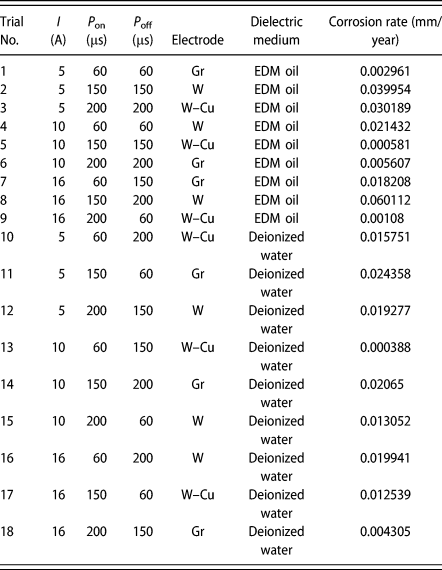
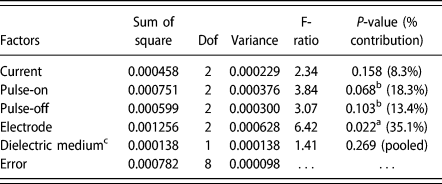
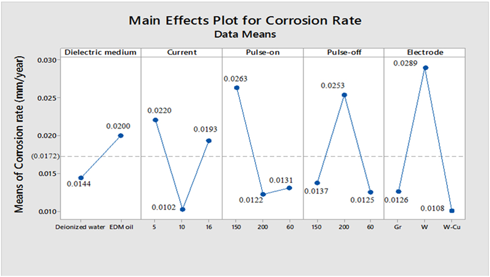
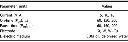
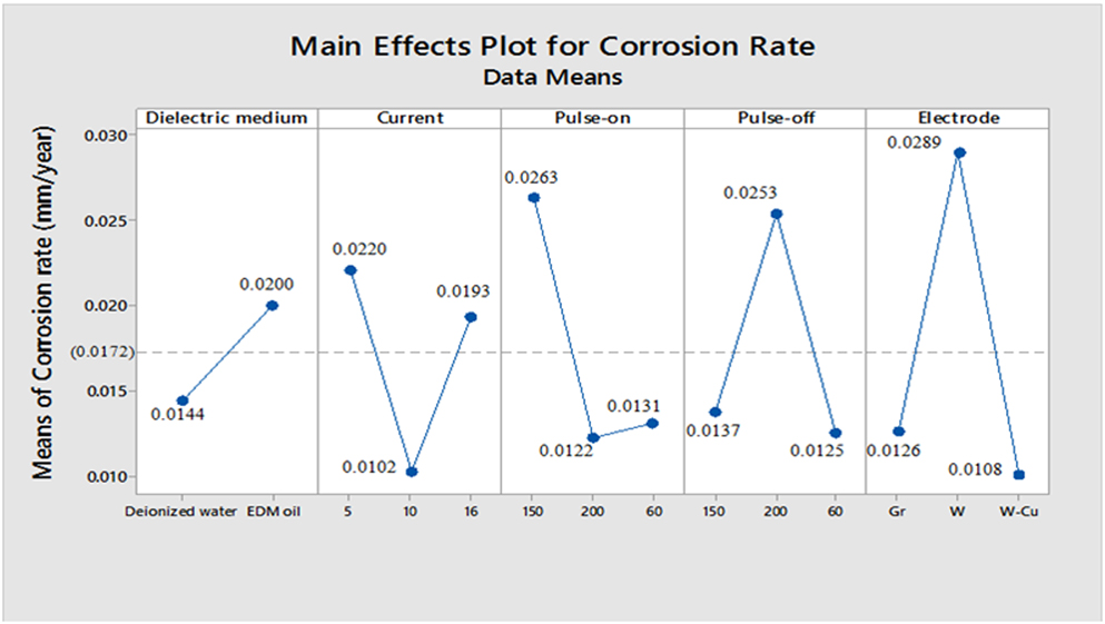
The experimentation was conducted according to L18 orthogonal array with five independent variables such as current, pulse on-time, pause time, electrode materials, and dielectric medium. The experimental layout and results are given in Table I. The corrosion behavior was observed from the anodic and cathodic slopes. The corrosion parameters such as corrosion potential (E corr), corrosion current density (I corr), corrosion rate, and polarization resistance (R p) are calculated by the intersection point of the cathodic and the anodic Tafel slope via Nova computer software. The analysis of variance (ANOVA) for corrosion rate (Cr) of machined surface was completed and the results are given in the last column of Table II. The factors with the larger value of F-test indicate its significance in controlling the corrosion rate. Similarly, the P-value symbolizes the significance level for each factor. From the results, it is clear that the selection of electrode material is the most significant factor followed by pulse on-time and pause time. On the other hand, the effect of the dielectric medium is negligible; consequently, it was factor-pooled (Ref. Table II). The main effect plot of selected input parameters is presented in Fig. 1. The Fig. 1 reveals that the optimum result was achieved on EDMing the surface in the presence of deionized water using W–Cu electrode at 10 A current and a pulse on-time set at 200 µs coupled with a lowest pulse pause time (i.e., 60 µs). The authors conducted the further exploratory investigation on the samples selected from trials conducted.
L18 Experimental design layout and results.

Analysis of variance for corrosion rate.

a Most significant (95%).
b Significant (90%).
c Pooled factor.
Main effect plot for corrosion rate.
Electrochemical corrosion analysis
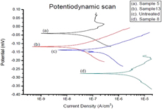
The potentiodynamic polarization curves of the untreated and selected electrical discharge treated Co–Cr samples were compared in Fig. 2. The untreated sample possesses a corrosion potential (E corr = −136.26 mV), corrosion current density (I corr = 181.26 nA/cm2), and corrosion rate (Cr = 0.0020251 mm/year). Furthermore, it was noticed that the corrosion resistance for the sample treated according to trial 13 exhibited the highest corrosion resistance (Cr = 0.0003 mm/year). Similarly, the sample treated according to trial 5 (Cr = 0.0005 mm/year) and trial 9 (Cr = 0.001 mm/year) also had significantly lower corrosion rate as compared to the untreated sample, thus depicting higher corrosion resistance incurred after surface modification. Whereas, it was also found that the surface treated as per trail 8 becomes highly corrosive and even higher than the untreated surface.
Potentiodynamic polarization curves of (a) sample 5 (I = 10, P on = 150, P off = 150, electrode = W–Cu, EDM oil), (b) sample 13 (I = 10, P on = 60, P off = 150, electrode = W–Cu, deionized water), (c) untreated sample, (d) sample 8 (I = 16, P on = 150, P off = 200, electrode = W, EDM oil).

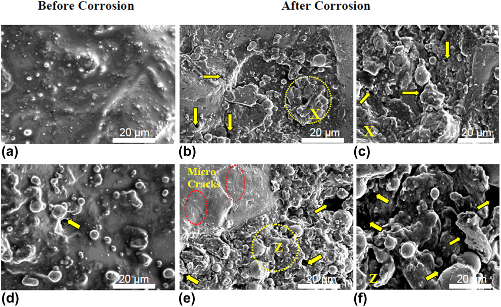
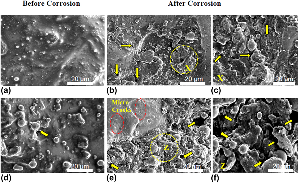
Figures 3(a) and 3(d) illustrate the surface topography of the EDMed surface. The irregular surface texture, micropores, and resolidified metallic droplets were observed on the as-received machined surface. After conducting corrosion test, sample 13 [Figs. 3(b) and 3(c)] exhibited low corrosive damage; however, sample 8 [Figs. 3(e) and 3(f)] depicts the high degree of irregularities, wider pitting, and microcracks.
SEM images from sample 13 (a–c) and sample 8 (d–f) treated surfaces before and after corrosion testing. Both surfaces demonstrate rough, porous grain with distinctive melting drops [mark (arrow): → corresponds to porous texture and melting drops; magnified at X and Z]. After corrosion testing, sample 13 shows low surface irregularities as compared to sample 8.
Hemocompatibility analysis
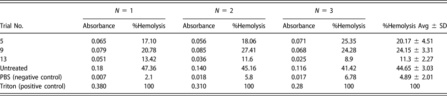
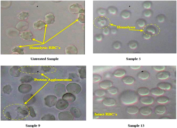
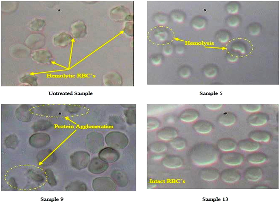
The treated samples showing the excellent corrosion resistance such as trials 13, 5, and 9 and untreated sample were examined for their hemolysis behavior. The Triton X™_100 (positive control) confirmed maximum hemolysis (100%), whereas PBS, pH 7.4 (negative control) yielded 4.89 ± 2.01%. It was observed that the untreated sample represented considerably higher hemolysis (44.65 ± 3.03%) in comparison with negative control (P < 0.001). However, electrical discharge treated sample 13 demonstrated significantly higher hemocompatibility. The results of hemolysis between sample 13 and the negative control were found in the insignificant difference (P > 0.05). Whereas, sample 5 (% hemolysis = 20.17 ± 4.51) and sample 9 (% hemolysis = 24.15 ± 3.31) had significantly higher hemolysis comparable to negative control (P < 0.05). The samples absorbance (Abs) and their respective percentage hemolysis values are illustrated in Table III. To validate these hemolysis results, red blood cell (RBC) morphology of these samples was investigated under a biological microscope as demonstrated in Fig. 4.
Absorbance and % hemolysis responses (where N = no. of attempts).

RBC morphology of EDM treated and unmachined specimens.
XRD analysis
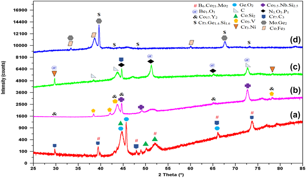
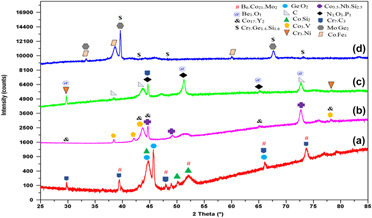
The X-ray diffractometer (XRD) patterns of the untreated and treated surfaces (sample 5, sample 8, and sample 13) are depicted in Fig. 5. All specimens comprised of basic element of Cr, Ni, Mo, and Co and also its compounds. The electrical discharge treated sample 5 offered superior corrosion resistance as a result of the formation of tetragonal structured oxide (GeO2), orthorhombic structure of carbide (Cr7C3), and cubic structured of boride (B6Co21Mo2) on the surface [Reference Yu, Khor and Sundararajan25, Reference Natesan and Johnson26]. Additionally, sample 13 exhibited thin oxide layer on the surface. The phases formed on the surface were cubic structured beryllium (Be1O1) and monoclinic structured phosphorous nitride (N1O1P1). The increase in O and P content may be credited to the strengthening of the corrosion protection and also promote the bioactivity of the bioimplant [Reference Mahajan and Sidhu27, Reference Jenko, Gorensek, Godec, Hodnik, Batic, Donik and Dolinar28, Reference Im, Akiyama, Habazaki, Kawashima, Asami and Hashimoto29]. In the case of sample 8, it was observed that the development of hexagonal vanadium and cubic yttrium like compounds on the surface significantly promotes the corrosion rate [Reference Lai30]. Furthermore, the absence of oxide layer on sample 8 favors rapid corrosion rate as compared to the other samples.
XRD pattern of Co–Cr specimen: (a) trial 5, (b) trial 8, (c) trial 13, and (d) untreated surface.

Discussion
This study elucidated the electrochemical corrosion resistance and hemocompatibility response of medically graded Co–Cr alloys. The potentiodynamic polarization curves calculated the corrosion current and potential. Amidst all samples (untreated and EDMed), the sample 13 was found to be higher corrosion resistant (I corr = 35.1150 nA/cm2, Cr = 0.0003 mm/year). The results of the corrosion resistance of Co–Cr alloy were compared with previous researches. Likewise, Yang et al. [Reference Yang, Shi, Li, Lei and Nie31] found that (2 mass%) addition of copper in the Co–Cr alloy offered higher corrosion resistance (I corr = 3.40 µA/cm2) in their research. Similarly, Tuna et al. [Reference Tuna, Pekmez and Kurkcuoglu32] reported that the Co–Cr samples which were fabricated by CAD/CAM milling and laser sintering had higher corrosion resistance (I corr = 16.88 µA/cm2) than other conventional casting methods. Whereas, Qiu et al. [Reference Qiu, Yu, Zhang, Smales, Zhang and Lu33] concluded that after the simulated porcelain firing process, the corrosion current value of Co–Cr alloy showed a minor decrement in I corr value. Low corrosion current of a material implicit high corrosion resistance. Hence, from the current study, it was observed that surface treatment of Co–Cr specimen (sample 13) by thermoelectric process namely EDM exhibited enhanced corrosion resistance as compared to other techniques. Furthermore, the specimen’s treated surface interactions with blood cells were evaluated by hemocompatibility test. Also, sample 13 demonstrated lesser hemolysis and higher density of intact RBCs. Whereas, clumped, accumulated, and distorted RBCs images were witnessed in the untreated sample. However, the treated samples 5 and 9 depicted improved RBC morphology compared with the untreated surface. It was also noted that by exposing RBCs on the surface of sample 9, the protein agglomeration on the RBC surfaces occurred and it is represented as blurred background in microscopic images (Fig. 4). The protein agglomeration on the RBCs was not observed in sample 13; thus, it also confirms its excellent hemocompatibility. ANOVA results revealed the optimum EDM process parameters (current = 10 A, pulse-on time = 200 µs, off time = 60 µs, machining in deionized water by utilizing W–Cu electrode) to obtain the most favorable results.
Conclusions
The surface of the Co–Cr alloy hip joint specimen was processed by EDM to scrutinize the corrosion behavior via electrochemical study. The study demonstrated that the treated sample confirmed the enhanced corrosion resistance as well as hemocompatibility. It is evident that the W–Cu electrode material proved to be the most significant factor demonstrating excellent corrosion resistant surface. The combination of high pulse on-time and low pulse pause time contributed to biofavorable surface alteration of the substrate. Moreover, these treated substrates also had an excellent interaction with human blood that confirms the hemocompatibility. XRD analysis revealed that the formation of carbide, oxide, and boride layers on the treated surfaces promotes the corrosion resistance as well as the bioactivity. EDM treated Co–Cr alloy shows promising results that can further be studied for their usage in clinical applications. Moreover, the study can be expanded to investigate the tribological behavior of EDM treated surface.
Methodology
In this research, medical grade Co–Cr–Mo alloy applied for knee or hip joint was selected for the experimentation. The implant was procured from DePuy Synthes Company (Raynham, Massachusetts). The chemical composition of this alloy is cobalt with 28.5% chromium, 6% molybdenum, 0.7% silicon, 0.5% manganese, 0.25% nickel, 0.22% carbon, 0.2% iron, 0.01% titanium, and 0.02% phosphorus [Reference Mahajan and Sidhu27]. The specimen was extracted into rectangular pieces from the supplied Co–Cr implant specimen. The surface was polished with emery paper (material: silicon carbide, grade P1000) and cleaned with ethanol solution before machining. Eventually, these specimens were treated with three different electrodes such as finely grained (particles sized ∼5 µm) graphite electrode, tungsten electrode, and tungsten–copper electrode (W/Cu −75/25; make: NICKUNJ, New Delhi, India) in die sinking EDM (make: Electronica Hitech Machine tools Pvt., Ltd., Maharashtra, India) with negative polarity [the workpiece (−) and tool electrode (+)] at assorted pulse pause time (60, 150, 200 µs). The working gap voltage between the electrodes was predetermined at 140 V which consent to the appropriate side flushing conditions. The samples were treated within two different dielectric media such as mineral oil (EDM oil) and deionized water to assure the process reliability. In this process, 16 A and 200 µs was the maximum limit of current and pulse on-time, respectively, and as beyond this limit, arcing or unstable machining was reported on the workpiece. After EDM treatment, the samples were extracted in circular form (10 mm diameter, 3 mm thickness) by a wire-EDM process for the corrosion and biological testing. Table IV indicates the process parameters and levels used in the experiments.
Parameter descriptions and values.

Electrochemical corrosion measurements
The electrochemical corrosion action of the untreated sample and EDM treated samples of Co–Cr alloy was analyzed by performing potentiodynamic polarization tests. The tests were carried out on Potentiostat/Galvanostat (make: Autolab, Utretcht, The Netherlands) interfaced with Nova software supported system. The electrolyte used for simulated human body fluid (SBF) condition was Ringer’s solution (Nice Chemical Pvt., Ltd., Cochin, India) at pH 7.2 with the chemical composition (in g/L) as 9 NaCl, 0.43 KCl, 0.2 NaHCO3, and 0.24 CaCl2. Before conducting the corrosion studies, the specimens were immersed in SBF solution for 24 h for the stabilization. In this test, the Co–Cr sample was utilized as a working electrode, the platinum (Pt) rod as a counter electrode, and silver/ silver chloride (Ag/AgCl) saturated calomel electrode (SCE) as a reference electrode, respectively. The scan rate of 1 mV/s was fixed for performing the experiments, and for each test, the fresh solution was used. Three trials were conducted on each experimental condition. The corrosion rate, current density, and corrosion potential were determined using the Tafel exploration plots. Polarization curves were actuated at −0.1 to +0.1 mV relative to open circuit potential. The corrosion rate (mm/year) is calculated by using
 $${\rm{Cr}} = {{{I_{{\rm{corr}}}} \times K \times {\rm{EW}}} \over {d \times A}}\quad ,$$
where Cr is the corrosion rate (mm/year); I corr is the corrosion current in amperes, where 1n A = 10−9 A; K is the constant, value = 3272 mm/(A cm year); EW is the equivalent weight of Co–Cr alloy, value = 28.011 g/mol; and d is the density of alloy, value = 8.3 g/cm3.
In vitro hemolysis test
Hemolysis test was executed to examine the human blood compatibility with electrical discharge treated surfaces, on selected highly corrosive resisted surfaces. The substrates surfaces were sterilized at 121 °C for 20 min in an autoclave (make: Accumax, New Delhi, India) to remove the foreign particles and micro-organisms. Further, the in vitro hemolysis test was performed on the surfaces by direct contact of these samples with human blood, which examines the RBCs lysis. An isotonic PBS having pH of 7.4 is accepted as a negative control due to its negligible hemolysis of RBCs and Triton Xtm-100 is used as a positive control which leads to 100% hemolysis of RBCs. The healthy human blood was collected in heparinized microcentrifuge tubes and then centrifugation of these blood tubes to 2500 rpm at 4 °C for 5 min to separate the RBCs. Then plasma and a buffy layer of leukocytes (supernatant) were removed, and residuals were washed thrice by an isotonic 7.4 pH phosphate buffered saline (PBS) to acquire a pellet of RBCs, and a collection of 1% of RBC suspension was used in the further process. The 108 wells plate dish was utilized to place the samples (the treated surface of the samples was exposed outward) and direct contact of 1 mL of the RBC suspension (1%) with each sample into each well. At 37 °C, all the samples were incubated for 1 h, and then microcentrifuge tubes were employed to collect the RBC suspensions, which were withdrawn from each well of the plate. After this, centrifugation of these tubes occurred at 4 °C, 2500 rpm for 5 min. The supernatant was collected, and through spectrophotometric technique, the sample absorbance was computed at 540 nm [Reference Dora, Kushwah, Katiyar, Kumar, Pillay, Suresh and Jain34]. Later, all experiments were executed in triplicate. The % hemolysis was calculated as,
 $$\% {\rm{hemolysis}} = {{{\rm{ABs}}} \over {{\rm{ABp}}}} \times 100\quad ,$$
where ABp is the absorbance of positive control and Abs is the absorbance of testing samples.
The Olympus microscope (model: CX 41, make: P. Bhogilal Pvt., Ltd., Kolkata, India) was employed to study the RBC morphology on the sample. In order to fix the RBCs, 0.5% glutaraldehyde in PBS was mixed with incubated RBC pellet for 1 h, and additional incubation was carried out for this mixture for 1.5 h at 4 °C. Further, the process followed the centrifugation at 2000 rpm and at 4 °C to eliminate the free glutaraldehyde. Thus, RBC pellet was acquired and these were washed three times with distilled water. Finally, RBCs were dispersed on a glass slide and coverslip placed on it to envision the RBC morphology under a microscope with the F.N.22, the eyepiece. The 6 V and 30 W halogen bulb in microscope illuminates the RBCs on a glass slide, and the cell responses were observed at different magnifications.
Scanning electron microscopy (SEM) and XRD analysis
The morphology of samples after EDM was investigated using SEM (JSM-6610 LV, JEOL, Tokyo, Japan). This technique was also utilized to investigate the corrosion behavior of the electrical discharge treated samples. The chemical composition and material transfer on the machined samples were examined by XRD (PANalytical X’Pert Pro MPD, Etten Leur, The Netherlands).
Supplementary material
To view supplementary material for this article, please visit https://doi.org/10.1557/jmr.2019.73.
Acknowledgments
The authors thank IKG Punjab Technical University, Kapurthala for its support of this research work.