1. INTRODUCTION
1.1. Feature modeling
Feature modeling is a design paradigm that comes as an alternative to the traditional geometry-based design systems. The founding idea of feature modeling is to focus the modeling tasks of the designer on a higher level, facilitating the specification of many different aspects in a product model, and gaining insight into their interrelations (Shah & Mäntylä, 1995). This is achieved by enabling the designer to associate functional information to the shape information in the product model.
Although one cannot find a consensual definition of the concept of feature, one that nicely fits to this research defines a feature as “a representation of shape aspects of a product that are mappable to a generic shape and are functionally significant for some product life-cycle phase” (Bidarra & Bronsvoort, 2000). In contrast to conventional computer-aided design (CAD) systems, in which the design focus mainly lies on geometry, in a feature modeling system the designer builds a model out of features, each of which has a well-defined semantics. As an example, for manufacturing planning purposes it would be appropriate to provide the designer with features that correspond to the manufacturing processes available to manufacture the product being designed (e.g., slot, pocket, and hole features).
Feature model semantics is mostly represented by a variety of constraints. Constraints can be used in feature modeling systems to express characteristics of the model (e.g., to specify some feature faces to be coplanar, or restrict the volume of a product to a certain maximum). However, above all, constraints are used as the internal constituents of features that express their semantics (e.g., a hole feature could have constraints to position and orient it, or constraints that express the physical limits of the drilling machinery available). Because of this central role of constraints, feature modeling systems have to make an intensive use of constraint solving techniques. In particular, geometric constraints and geometric constraint solving techniques are very common.
To ensure that feature model semantics is maintained, the validity of the feature model has to be checked after each model modification. Feature model validity is usually checked by solving the constraints in the model: a valid feature model is a feature model that satisfies all its constraints. Modeling systems that guarantee feature model semantics to be maintained throughout the modeling process are called semantic feature modeling systems (Bidarra & Bronsvoort, 2000).
1.2. Interactive manipulation of features
The specification and the modification of feature parameters that determine the position, orientation, and dimensions is in current modeling systems mostly done through the input of values in dialog boxes, after which the model is updated accordingly. The disadvantages of this approach are that redesigning is time-consuming due to the inefficient feedback, the insight given on the consequences of an operation is poor, and user interaction lacks intuitiveness as, for example, the relation between a feature parameter and the model is not always clear. As a result, all too often designers are forced into using a trial and error approach to find the right feature parameter to be changed or to find the right value for the parameter.
Good interactive facilities for direct manipulation of features should always deal with the three drawbacks just mentioned. In this research, we developed a new approach that allows the designer to interactively select a parameter of a feature in the model, and subsequently modify its value while being provided with real-time feedback on the consequences of the operation. When the designer is satisfied with the model, he can choose to provisionally accept the changes and, eventually, let the system check the model validity.
This article describes the most crucial aspect of this approach: being able to provide real-time feedback on the changes effected to the feature model. Because this visual feedback has to be generated several times per second to support interactive modification of a feature parameter value, all geometric constraints have to be solved several times per second. Although techniques exist that enable geometric constraint models to be solved multiple times per second, these techniques are either only applicable to a specific constraint solving approach, or require a considerable implementation effort. The major challenge in this regard was, therefore, to come up with a technique that reduces the time needed to solve a geometric model, can be applied with a variety of geometric constraint solvers, and can be easily implemented.
The paper deals with the situation in which a real-valued feature parameter that determines a dimension, or position, or orientation of a feature in a fully specified feature model, is interactively manipulated by a designer. Fully specified, here, means that the designer has specified every aspect of the geometry that is represented by the model. Therefore, when a feature parameter is manipulated, only those aspects of the geometry that are dependent on it can possibly change. Note that these changes can affect several features, because features typically are dependent on each other.
We first give an overview of previous research on constraint-solving techniques related to interactive applications (Section 2). Next, we analyze the requirements for interactive feature manipulation (Section 3) and focus on the crucial problem of model compilation, for which we have developed a new approach that satisfies the above requirements (Section 4). After that, we describe a prototype implementation of the new model compilation approach (Section 5), and discuss its performance (Section 6). Finally, we present some conclusions (Section 7).
2. CONSTRAINT SOLVING IN INTERACTIVE APPLICATIONS
In general, constraint solvers are too slow to be used in interactive applications, in which the value of one or more constraint variables is changed interactively by a user and the constraint model has to be solved in real time to provide feedback. This is because the necessary constraint solving algorithms are too complex to be executed in real time.
Various people have been working on techniques to enable constraint solvers to be used in interactive applications, such as user interface construction (Borning & Duisberg, 1986; Freeman-Benson, 1993; Hosobe, 2001), and geometric modeling systems (van Emmerik, 1991; Hsu et al., 1997). Some focused on reducing the complexity of the model such that it can be solved in real time, others focused on enabling a specific constraint solver to solve constraint models in real time, whereas others focused on techniques to reduce the size of the constraint model, which can be applied with any constraint solver. Some characteristic examples of these classes of approaches are given below.
Van Emmerik (1991) describes an interactive, constraint-based, three-dimensional (3-D) geometric modeling approach that uses noncyclic constraint models with predefined solving order, which can be solved in real time. In this approach, the geometric model is represented by geometric primitives that are dimensioned and positioned by means of the so-called geometric tree. The geometric tree is a 3-D structure of local coordinate systems, each with three translation, three rotation, and three scaling parameters relative to its parent. The geometric tree initially contains a root coordinate system, and new coordinate systems can be fixed to the root coordinate system or other coordinate systems by using constraints. Because of the simple structure of the constraint model, it can be solved by a local propagation-based constraint solver in real time. The constraint solver evaluates the geometric tree by starting at the root node, and solving the constraints in the order in which they have been specified. Disadvantages of this approach are that it does not support cycles, and does not allow the specification of constraints that relate a coordinate system to another one that had been created after it.
Kramer (1992) describes a geometric constraint solver based on degrees of freedom analysis, which splits the constraint solving process into an analysis phase that is independent of the actual values of the constraint variables, and an execution phase that depends on the result of the analysis phase and the actual values of the constraint variables. In the analysis phase, the structure of the constraint model is analyzed and a metaphorical assembly plan is generated, which describes the sequence of actions that have to be performed to satisfy the constraints in the model. In the execution phase, the actions from the metaphorical assembly plan are executed based on the actual values of the constraint variables, resulting in a model that satisfies all constraints. In case the value of a constraint variable needs to be changed several times, the execution phase is performed for each new value of the constraint variable to satisfy the constraints. The analysis phase only needs to be performed after the structure of the constraint model has changed, that is, after a constraint has been added, changed, or removed. A disadvantage of this approach is that each time the value of a variable is changed, typically half the number of constraints in the model has to be solved.
Hsu et al. (1997) describe another constraint solver based on degrees of freedom analysis, which also splits the constraint solving process into an analysis phase that is independent of the actual value of the constraint variables, and an execution phase that depends on the result of the analysis phase and the actual values of the constraint variables. The analysis phase results in a dependency graph, which is a directed version (of a subset) of the original constraint graph, and which indicates the order in which the constraints have to be solved to satisfy all constraints in the model. In the execution phase, the constraints are satisfied in the order specified by the dependency graph, resulting in a model that satisfies all constraints. In case the value of a constraint variable needs to be changed, first a limited analysis is performed once to create the specialized dependency graph with the constraints that need to be solved if the value of the constraint variable is going to be changed. Subsequently, the execution phase is performed for the constraints in the specialized dependency graph each time the value of the constraint variable is actually changed. The advantage of this approach with respect to the approach presented by Kramer is that a minimal subset of constraints is solved each time the value of the constraint variable is changed. A disadvantage is that it can only be applied with a constraint solver that provides dependency graphs.
Weigel and Faltings (1999) describe an approach that is independent of the constraint solver used, and aims at compiling the rigid structures in the constraint model into structures that need less time to satisfy the constraints in it. The resulting constraint model is subsequently solved by the same, unchanged, constraint solver that was used to solve the original model, but in less time. The approach exploits interactions between three types of compilation techniques: consistency, decomposition, and interchangeability. Consistency techniques prune certain values or value combinations from the set of possible solutions of the constraint model, and thus reduce the work that needs to be done by the constraint solver. Decomposition techniques can determine substructures such that the complexity of solving the model is dominated by the complexity of solving the substructures. Interchangeability techniques use the idea of exploiting equivalences between different variable values: for variable X, a value a is interchangeable with b exactly if, whenever there is a solution where X = a, there is another solution where all assignments are identical except that X = b, and vice versa. An example of an interaction between these techniques that is exploited is that after compiling a constraint model using a consistency technique, new opportunities might appear to further compile it with an interchangeability technique. A complexity analysis of the complete approach is not given in the paper, but it is mentioned that although the compilation technique itself could be very slow, it can result in a significant performance gain at run time. The advantage of this approach with respect to the approach presented by Hsu et al. (1997) is that it is independent of the constraint solver used. The disadvantage is that it requires excessive programming to implement the techniques.
In conclusion, existing techniques do not optimally reduce the number of constraints to be solved when modifying a particular constraint variable, are only applicable to certain constraint solvers, or require intensive programming to be implemented.
This paper presents a new technique that optimally reduces the number of constraints to be solved when modifying a particular constraint variable, can be applied to many existing geometric constraint solvers, and requires little programming. This technique capitalizes on the constraint solver used in order to compile the original constraint model into a specialized constraint model to be used when modifying a particular constraint variable.
The new technique is presented in the context of geometric constraint models, consisting of, among others, distance and angle constraints, in which cycles are allowed, and which are well constrained. Well constrained means that there is a limited number of solutions to the constraint problem (Joan-Arinyo et al., 2003). In our context, the number of solutions of a constraint model is typically 1.
Manipulation in this context involves changing the value of real-valued constraint variables of geometric constraints, such as the variable that represents the distance or angle that should be enforced by a distance or angle constraint, respectively. Depending on the number of real-valued constraint variables associated with the feature parameter that is manipulated, several such variables may be affected at the same time. Take, for example, a pattern feature, consisting of two cylinder shapes, and its feature parameter height, associated with the real-valued constraint variables specifying the height of each cylinder shape; then, manipulation of the feature parameter height results in manipulation of both real-valued constraint variables.
3. MANIPULATION OF FEATURES
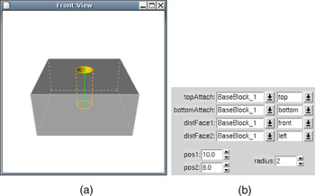
A feature can be modified by manipulating the value of the parameters of the feature. Although a parameter of a feature can also be a face of another feature to which it is attached, or with respect to which it is positioned, this article only deals with manipulation of real-valued feature parameters, such as the dimension of the shape of a feature, the distance of a feature with respect to a face of another feature, and so forth. An example of a through hole feature with its parameters is given in Figure 1.

(a) A through hole feature and (b) its parameters. [A color version of this figure can be viewed online at www.journals.cambridge.org]
3.1. Direct feature manipulation
Direct manipulation of a real-valued feature parameter consists of two phases. In the selection phase, the parameter to be manipulated has to be selected. In the interaction phase, the value of the parameter is changed by the designer, and the feature model is updated accordingly by the system.
In the interaction phase, the designer changes the value of a feature parameter by using the mouse to drag an icon that represents the feature parameter on the image of the displayed feature model. During the dragging, the model and its visualization are updated continuously to reflect the modifications. Only the aspects of the model that depend on the feature parameter being manipulated should be updated, to avoid that the designer becomes distracted by irrelevant changes. The fact that the constraint model representing the feature model is well constrained (see Section 2), guarantees that no irrelevant changes can happen.
The interaction phase needs to be performed in real time, because the designer needs the feedback of the image of the changed model on the display while dragging the mouse. Real-time here means fast enough to preserve the illusion of movement, that is, the illusion that consecutive images of the same object in a somewhat different position, show a moving object. The illusion of movement is preserved when the system presents more than 10 frames (or images) per second (Card et al., 1983).
3.2. Model validity maintenance
Manipulating the parameter of a feature in a model may turn a valid feature model into an invalid one (see Section 1.1), for example, because an undesirable interaction occurs between two features, or a dimension does not satisfy its dimension constraint anymore.
An invalid situation should preferably be detected during the manipulation of the model, and the designer should preferably be immediately informed on it. In case that it is not feasible to detect the invalid situation during the manipulation of the model, for example, because it takes too much time to check the validity of the model, the validity of the model should be checked as soon as the manipulation of the model is ended.
However, in case a model has become invalid during manipulation of a feature parameter, further manipulation should not be prohibited, because the model may turn valid again if the value of the parameter is changed even more. For example, if the model of Figure 1 would also contain a through slot that is positioned to the left of the hole, and the through slot would be moved to the right by manipulating its position parameter, then, as the through slot and the hole start to overlap, the model becomes invalid, but the model turns valid again if the through slot is moved beyond the hole.
If the model is invalid at the moment that the manipulation of a feature parameter is ended, then some validity maintenance mechanism (Bidarra & Bronsvoort, 2000) should be triggered to assist the designer to make the model valid again.
3.3. Constraint management
To solve the geometric constraints in the model, a constraint management scheme is used. The constraint management scheme maps the high-level constraint model with the (complex) design constraints to a low-level constraint model with primitive constraints that can be solved by the constraint solvers used, and updates the high-level constraint model based on the low-level constraint model after solving.
However, the low-level constraint model of typical feature models generally consists of 100+ constraint variables. Most constraint solvers are too slow to solve these during interactive feature manipulation, given the high complexity of constraint solving algorithms.
Fortunately, in the interaction phase of interactive feature manipulation, only a part of the constraint model needs to be solved. Because only one feature parameter is changed during the interaction phase, typically, large parts of the model do not change, that is, they are rigid. Such rigid parts can, therefore, be represented by a single constraint variable in the low-level constraint graph, thus avoiding the need to solve all constraints within these parts.
Constraint management for interactive feature manipulation should thus identify all rigid parts of the model, and map each one to a separate constraint variable in the low-level constraint model that is solved in the interaction phase. The resulting, simple, constraint model can be used to find the relative position and orientation of the rigid parts during the interaction phase, given the current value of the feature parameter that is beeing changed.
Although the rigid parts of the model can be found using the algorithms presented by Hsu et al. (1997) and Weigel and Faltings (1999), this article proposes the generation and use, for this purpose, of a special constraint model, because this approach can be applied with many geometric constraint solvers and requires little implementation effort. The only requirement to the constraint solver is that it should be able to solve an underconstrained model, and return information on the rigid parts in such a model.
The next sections describe such a constraint solver-driven model compilation approach.
4. CONSTRAINT SOLVER-DRIVEN MODEL COMPILATION
In the constraint solver-driven model compilation approach, the original constraint model is compiled into a manipulation constraint model that is optimized to reduce the time needed to validate the feature model after manipulating a specific feature parameter. The compilation is performed by a constraint solver. The optimization is based on the notion that, in general, a change to the value of a certain feature parameter causes only limited changes to the feature model, which was described in Subsection 3.3.
4.1. Generating the manipulation constraint model
The manipulation constraint model is generated in the selection phase of the interactive feature manipulation process. It is generated only once when a feature parameter is selected to be manipulated.
The manipulation constraint model contains a constraint variable for each rigid part of the original constraint model, and the constraints between these rigid parts. The constraint variables within a rigid part in the original constraint model are replaced by a single constraint variable in the manipulation model, which represents the position and orientation of the rigid part. The constraints between the constraint variables within a rigid part are discarded in the manipulation model, because their relative position and orientation will not change during the manipulation phase. The constraints between the constraint variables of different rigid parts in the original constraint model are in the manipulation constraint model between the constraint variables that represent the rigid parts.
The manipulation constraint model is generated by a constraint management approach that uses the constraint solver to find the rigid parts in the model. The constraint management approach finds the rigid parts in the model by having the constraint solver solve the original constraint model except for the constraints that represent the feature parameter that is changed. Based on the rigid parts found, the constraint management approach generates the manipulation model.
Discarding the constraints that represent the feature parameter that is changed, results in an underconstrained constraint model with multiple well-constrained (Joan-Arinyo et al., 2003) submodels. Each well-constrained submodel represents a region of the feature model that remains rigid if the feature parameter is changed. Although it is not necessary to minimize the number of well-constrained submodels, reducing the number of submodels cuts down the time needed to solve the resulting manipulation constraint model.
The constraint solver that is used by the constraint management approach to solve this model should be capable of solving such underconstrained models and returning the submodels that are well constrained. These capabilities are owned by many geometric constraint solvers.
The constraint management approach generates the manipulation constraint model based on the information on the well-constrained or rigid parts of the model that is returned by the constraint solver. It creates a constraint variable in the manipulation constraint model for each rigid part in the original constraint model. In addition, it analyzes the original constraint model to find the constraints between the rigid parts; for each constraint it finds, it creates an identical constraint between the constraint variables in the manipulation constraint model that represent the rigid parts. These constraints include the constraints that represent the feature parameter whose value will be changed.
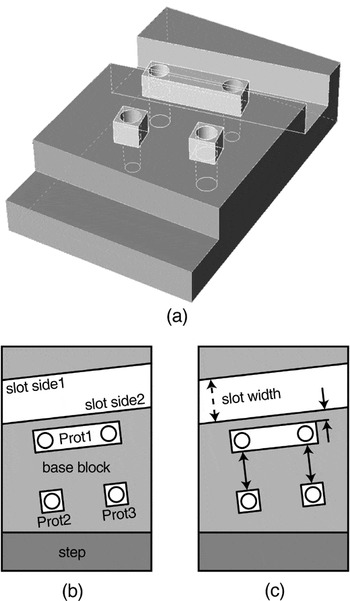
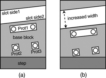
A simple example of the generation of the manipulation constraint model will be given based on the manipulation of the width of the slanted slot in the feature model of Figure 2a. The designer will manipulate the width of the slanted slot, which in turn, will displace the slot side 2 (a side face of the slanted slot; see Fig. 2b). When slot side 2 is moved, prot1, prot2, and prot3 will move accordingly because they are positioned with respect to slot side 2, either directly or indirectly (see Fig. 2c).

(a) The feature model with the slanted slot that is interactively manipulated by the designer, (b) the names of the relevant entities of the model, and (c) the relevant relations in the model.
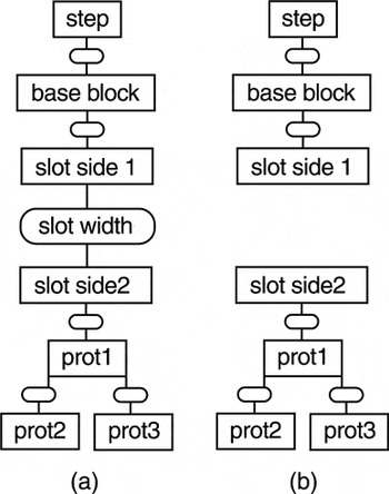
In the first step, the constraint model is generated that will be solved by the constraint solver to find the parts in the model that are rigid when manipulating the width of the slanted slot. The model is derived from the original constraint model of the feature model by copying all constraint variables and constraints except the constraints that represent the feature parameter to be manipulated. This results in an underconstrained model, in which the well-constrained parts or, more precisely, the not underconstrained parts, represent the parts of the model that are rigid when manipulating the width of the slanted slot (see Fig. 3).

(a) The part of the constraint model of the feature model of Figure 2 that is relevant for manipulation of the width of the slanted slot and (b) the constraint model that is derived from it to find the parts in the model that are rigid during this manipulation.
In the second step, the generated model is solved to find the well-constrained parts in the model, and thus find the parts of the model that are rigid during the manipulation. Here, there are two well-constrained parts: one that consists of the step, base block, and slot side 1, the other one consists of slot side 2, prot1, prot2, and prot3 (see again Fig. 3).
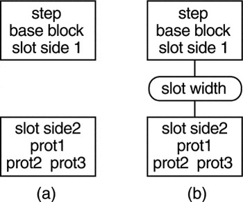
In the third step, the manipulation constraint model is generated based on the found well-constrained parts. Initially a constraint variable is generated for each well-constrained part (see Fig. 4a). After that, the constraints from the original constraint model that relate constraint variables from different well-constrained parts are created between the constraint variables that represent these well-constrained parts (see Fig. 4b).

The manipulation constraint model consists of (a) a constraint variable for each well-constrained part and (b) the constraints from the original model that relate constraint variables of different rigid parts.
4.2. Using the manipulation constraint
The manipulation constraint model is used in the validity checking subphase of the interaction phase of the interactive feature manipulation process.
The manipulation constraint model is solved each time the value of the feature variable that has been selected to be manipulated has been updated, to determine the changes in the model. Because the manipulation constraint model is typically quite small, it can of be solved in the validity checking subphase of the interaction phase without breaking the movement illusion of part of the model.
The changes to the manipulation constraint model are propagated to the original constraint model each time the manipulation constraint model has been solved. This consists of updating the value of the constraint variables in the original constraint model based on the value (i.e., position and orientation) of each of the constraint variables in the manipulation constraint model.
Figure 5 gives an example of the use of the manipulation constraint model model of Figure 4 for changing the width of the slanted slot in the feature model of Figure 2a. Each time the width of the slanted slot has been increased, this change is propagated to the original constraint model, that is, to the features (and entities of features) slot side 2, prot1, prot2, and prot3, which are moved accordingly in the feature model.

Each outcome of solving the manipulation constraint model is propagated to the feature model, which is smoothly modified from (a) to (b).
5. PROTOTYPE IMPLEMENTATION
The proposed approach to support interactive feature manipulation has been implemented in Spiff (Bronsvoort et al., 1997), a prototype feature modeling system developed at Delft University of Technology.
This section first describes the global constraint solving scheme used in the Spiff system. Subsequently, it describes in some detail the implementation of the proposed approach, focusing on the solving strategy followed in the compilation and use of the manipulation model. The section closes with a brief performance analysis of the current implementation.
5.1. Constraint model
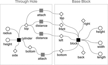
A feature model is represented in the Spiff system using several internal representations. One of these, on which we will focus, consists of the high-level constraint graph. In this graph, nodes represent both the variables and the constraints applied upon them, and edges represent the relationships established among these nodes. The high-level constraint graph thus aggregates the definitions of every feature in the model, as well as the relations between them. in the following, for simplicity, we will only deal with the geometric variables (e.g., faces and parameters) and with the geometric constraints in the high-level constraint graph (but it should be remarked that it contains quite a few other entities). These geometric constraints can either relate a feature with other features or specify internal solver restrictions between variables of the feature itself. Figure 6 presents a simplified version of a high-level constraint graph.

A high-level constraint graph for the simple model of Figure 1, consisting of a base block and a through hole.
The high-level constraint graph is maintained in Spiff by a constraint manager. In addition, the constraint manager disposes of several dedicated constraint solvers, among which the Kramer solver plays a central role for the purposes of this research. The Kramer solver works with a specific primitive constraint graph format, the so-called Kramer graph.
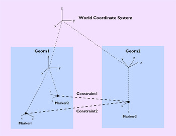
Just like the high-level constraint graph, in the Kramer graph the nodes describe constraints and variables, and the edges describe their relationships. In this graph, the variables are called geoms and represent a coordinate system that is in a specific position and orientation in space. The position and orientation are restrained by the constraints in the graph. By determining, for each geom, a position and an orientation that satisfy all constraints, the final values for the variables are set.
These geoms are actually more complex. They contain a number of dependent coordinate systems, called markers. Each marker's position and orientation is fixed relative to its geom's coordinate system, and therefore cannot move in relation to it. Even though the constraints are connected to geoms, in the Kramer graph, what they actually relate are markers inside those geoms. By specifying constraints on markers we indirectly specify constraints on the respective geoms.
Each constraint reduces the relative degrees of freedom between geoms by specifying restrictions to the position and orientation of its markers. The Kramer currently supports the following constraint types:
- the parallel-z constraint, specifying the z axes of two markers to be parallel;
- the coincident constraint, specifying two markers to have the same position;
- the in-plane constraint, specifying the position of a marker to lay on the plane defined by the x–y axes of the other marker; and
- the in-line constraint, specifying the position of a marker to be on the z axis of the other marker.
Further details can be found in Dohmen (1998). An example of a simple Kramer graph is given in Figure 7.

An example Kramer graph (Dohmen, 1998). [A color version of this figure can be viewed online at www.journals.cambridge.org]
5.2. Mapping from the high-level constraint graph to the Kramer graph
To create the Kramer Graph, each geometric variable and geometric constraint of the high-level constraint graph must first be mapped to the Kramer graph as one or more variables or constraints. Every geometric variable is mapped to exactly one geom whose position and orientation are fixed and orientation is the same as that of the original variable. As for the geometric constraints, the way in which the mapping is actually done varies. Generally, it consists of first creating one or more markers in each of the geoms that correspond to the geometric variables of the original constraint, and then creating a number of Kramer constraints relating these markers in a way that expresses the semantics of the original constraint.
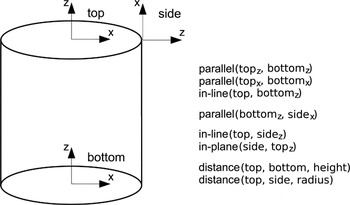
Figure 8 presents an extract of the Kramer Graph resulting from the mapping of a cylinder basic shape. This could, for example, be part of the mapping of the through hole in the example of Figure 6.

The mapped Kramer geometric variables and constraints of a cylinder.
Now consider the attach constraint between the top face of the through hole and the top face of the base block of the example in Figure 6. The two faces will be mapped each to one geom. The mapping of the attach constraint will create one marker in each of the geoms and add between these markers a parallel constraint and an in-plane constraint. These specify that the z axis of the two markers will have to be parallel and that the position of the first marker will have to be in the plane defined by the second marker.
5.3. Kramer solving strategy
To explain how the Kramer solving actually works, we first need to define the concept of joint. A joint is no more than the set of constraints between two geoms. This means a joint is what restricts how two geoms are positioned in relation to each other. We call a joint rigid if it leaves no relative degrees of freedom between the two geoms, that is, their position and orientation are fixed in relation to each other.
The Kramer solver works by iteratively determining which joints are rigid and joining them into new geoms called macrogeoms, which embed the old geoms (i.e., all the markers in the original geoms are placed in the new macrogeom). By progressively joining more and more geoms, a moment is reached when there is only one (macro)geom. At this point the system has been solved. From this single geom it is possible to update the coordinate systems of the original geoms by locating their markers in it.
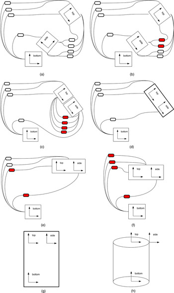
Figure 9 shows an iconic representation of the process for solving a Kramer graph. In Figure 9b and c, the constraints in the joint between the geom that represents the top face and the geom that represents the side face of the cylinder are processed, and it is detected that the joint is rigid. Consequently, in Figure 9d the two geoms with the rigid joint between them are merged into a macrogeom that represents both the side face and the top face of the cylinder. After that, in Figure 9e and f, the constraints in the joint between the macrogeom and the geom that represents the bottom face are processed, and it is detected that this joint is also rigid. Finally, in Figure 9g, the macrogeom and the geom that represents the bottom face are merged into a single resulting macrogeom, and in Figure 9h, the position of the original geoms is updated based on the information from that macrogeom.

An iconic representation of the solving process for the Kramer graph of the cylinder in Figure 8. The geoms are represented by the larger blocks that contain coordinate axes, and the constraints are represented by the smaller rounded rectangles. The constraints that are represented by the shaded rectangles are the ones that have already been processed. (a) Initial graph, (b) two constraints processed, (c) rigid joint detected, (d) merge geoms, (e) two constraints processed, (f) rigid joint detected, (g) merge geoms, and (h) solution found. [A color version of this figure can be viewed online at www.journals.cambridge.org]
In addition to the above strategy for rigid joints, a group of nonrigid joints that form a loop may fully determine the relative position and orientation of all the variables in that loop. In order for the solver to determine a solution for these loops, it attempts to rewrite their constraints using the techniques described in Dohmen (1998), in a way that turns some of the joints rigid.
One final remark is that the Kramer Solver is able to handle models that are not fully constrained. In this situation, it merges geoms up to the point where it can no longer find rigid joints, resulting in a graph with more than one remaining macrogeom. This characteristic is crucial for this approach, as will be explained in the next subsection.
5.4. Algorithm details
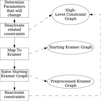
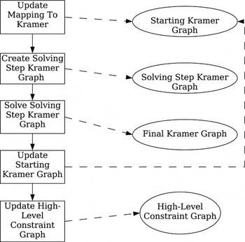
In this section we describe in more detail how the proposed approach was implemented in the Spiff system. The detailed outline of the algorithm is depicted in Figures 10 and 11.

The computation of the preprocessed Kramer graph.

Solving for each interaction step of the parameter modification.
5.4.1. Generating the preprocessed Kramer graph
When applying the generic approach described in Section 4 to our Kramer Solver implementation, what we need is to use the Kramer Solver to produce a new Kramer graph that encloses all the constraint solving results that are not related to the specific parameter being solved. In this way, one avoids repeating a significant amount of work in the subsequent solving process. For this reason, we call this result the preprocessed Kramer graph. The whole generation process is schematically depicted in Figure 10.
The first step in computing the preprocessed Kramer graph consists of determining which parameters will be affected by a given manipulation. This is easily achieved by adding a tag to each parameter that is set when the value of the variable is changed.
Subsequently, making use of the ability of the Kramer solver to handle underconstrained graphs, the computation of the preprocessed graph is performed taking the following steps:
- In the high-level constraint graph deactivate the constraints related to the parameter(s) affected by manipulation.
- Map the high-level constraint graph to the starting Kramer graph. This graph will not contain the Kramer constraints that correspond to the deactivated constraints, and will therefore be underconstrained.
- Solve the starting Kramer graph. The resulting graph will be used as the preprocessed Kramer graph.
- Reactivate in the high-level constraint graph the constraints that were deactivated in step 1.
5.4.2. Using the preprocessed Kramer graph
After the preprocessed Kramer graph has been generated, it is necessary, for the solving itself, to add to this graph the constraints related to the parameters that are affected by the manipulation (these were left out during the generation of the preprocessed graph). The resulting graph, called the solving step Kramer graph, is our manipulation constraint model. This is the second step in Figure 11, which describes what is done for each change in the parameter.
Updating the high-level constraint graph from the final Kramer graph for each solving step has to be done in two phases (see Fig. 11). In the first phase, the starting graph has to be updated. For this, the position and orientation of each of the geoms in the starting graph has to be found by searching for one of its markers in the single macrogeom in the final graph. This step is necessary because the geoms that correspond to each geometric variable of the high-level constraint graph only exist in the starting Kramer graph. Therefore, only after updating it can the second phase take place, in which the high-level constraint graph is updated. This is the last step in Figure 11.
6. PERFORMANCE ANALYSIS
The research goal of the present work (see Section 1) was to come up with a generic and easy to implement optimization technique able to significantly reduce the constraint solving time, in a way that enables a designer to interactively manipulate a real-valued feature parameter that determines a dimension or the position/orientation of a feature in a fully specified feature model. At this point, one can legitimately ask how efficient the constraint solver-driven model compilation approach described in the preceding sections is.
6.1. General considerations
As highlighted before, this approach is generic, in the sense that it can be applied to a large variety of geometric constraint solvers. Consequently, its absolute performance is inherently dependent on the absolute performance of the specific constraint solver used. Therefore, the relevant question can be formulated as follows: “for a given parameter modification, what is the improvement in the solving time provided by this optimization approach, compared to the solving time (Ts) required by the same solver without the optimization?”
In order to answer this question, one should distinguish two solving times in this approach: the compilation time, required to generate the manipulation constraint model, and the interaction time, required to solve the manipulation constraint model for each new parameter value. For a given parameter, the compilation time is spent only once, in the selection phase, that is, when the parameter to be modified is chosen. The interaction time, however, is repeatedly spent during the interaction phase, that is, every time the value of the chosen parameter is interactively modified by the user. The latter is, therefore, the most critical one from an interactivity point of view. In general, the two times are not necessarily related.
The compilation time primarily depends on the size of the original constraint model, that is, the number N of constraint variables in it. Secondarily, it also depends on the number of rigid parts identified in it during the compilation, that is, the number M of constraint variables in the resulting manipulation constraint model (which, ultimately, is dependent on the particular parameter chosen for manipulation).
The interaction time is mainly dependent on the size of the manipulation constraint model, that is, the number M of constraint variables in it. In this regard, one can ideally distinguish three situations: best case, average case, and worst case:
- Best case: The manipulation constraint model is the smallest possible, that is, it consists of two constraint variables representing two rigid parts; see for an example the operation on the model in Figures 4 and 5. In this situation, the compilation time should be comparable to time Ts required to solve the original constraint model for the same parameter modification. The interaction time, in turn, should be very low (roughly in the order of Ts/N), as the manipulation constraint model is very simple.
- Average case: In the average case, the value of a real-valued constraint variable only influences the relative position of a small number of rigid parts in the model, so the manipulation constraint model consists of a small number M of constraint variables. In these situations, the compilation time should be comparable to the time Ts required to solve the original constraint model for the same parameter modification; however, it is usually somewhat higher because, in addition to the constraint management overhead described in Subsection 4.1, the compilation typically involves solving an underconstrained model, possibly with cycles. The interaction time, in turn, should be expected to be a small fraction of Ts (roughly in the order of Ts × M/N).
- Worst case: The worst case conceivable is rather hypothetical, and not realistic in practice, at least within a feature modeling context. That would be the unlikely situation for which the manipulation constraint model generated would have the same number of constraint variables as the original constraint model, that is, M = N (in other words, no optimization can be achieved). In such a situation, the compilation time should typically surpass the time Ts required to solve the original constraint model, because the constraint management overhead is higher, and the compilation most likely involves solving an underconstrained model with cycles. Accordingly, the interaction time for such a manipulation model should be expected to be of the same order as Ts, the solving time for the original constraint model.
From a practical point of view, the best and average cases are the most relevant. In real-world models, parameter modifications will mostly result in a best case situation, with M = 2 (as exemplified in Subsection 4.1), or, otherwise, in an average case situation, with M much smaller than N. The following subsection describes and analyses some results of performance measurements on a prototype implementation.
6.2. Performance measurements
To evaluate the proposed approach, we measured the performance improvements of its Kramer implementation, described in Section 5, by performing a number of tests within the Spiff system, running on a 2.4-GHz Pentium 4 PC under Linux.
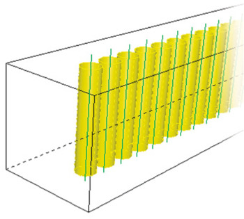
The three models used in the tests were all similar to the model shown in Figure 12, consisting of a block with a row of through holes, only differing in the number of holes present: 2, 10, and 20 through holes.

An example of a benchmark model used in the performance tests. [A color version of this figure can be viewed online at www.journals.cambridge.org]
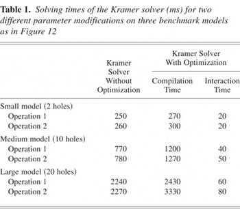
Two modeling operations were performed on each of these models. Operation 1 consists of modifying the radius of one of the through holes (i.e., a parameter on which no other feature parameter depends). Operation 2 consists of modifying the height of the block (i.e., a parameter that affects the height of every through hole in the model). Ultimately, both operations can be regarded as examples of the best case described above, differing only in the amount of overhead involved in the compilation process and in constraint management.
For each model and for each operation, the solving times measured are summarized in Table 1, and compared to the solving times taken by the Kramer solver without any optimization.
Solving times of the Kramer solver (ms) for two different parameter modifications on three benchmark models as in Figure 12

The most relevant observation about the measurements in Table 1 regard the interaction times, which lie between 3 and 8% of the solving time without optimization. Furthermore, the interaction times are very low, always below 100 ms, which leaves more than enough time to render each new frame as a feature parameter is interactively modified. We can, therefore, conclude that the presented approach fulfills the performance requirements stated in Section 1.
Despite these low interaction times, we should also remark that, for this Kramer solver implementation, solving the manipulation model for operation 2 takes indeed slightly longer than solving it for operation 1, which can be attributed to the higher overhead previously mentioned.
The compilation times for this Kramer solver implementation are in the same order of magnitude of (though higher than) the solving time without optimization, as was predicted in the analysis above. To understand why the compilation times are higher, one should realize that one of the steps of the Kramer Solver is the search and rewriting of the loops in the constraint graph (Kramer, 1992). When in underconstrained situations, the Kramer Solver has to search all the possible loops before it can conclude that it cannot merge any more geoms.
7. CONCLUSIONS
This paper presented a new approach to the optimization of geometric constraint solving for interactive feature model manipulation. The presented constraint solver-driven model compilation approach not only considerably reduced the number of constraints that have to be solved during interaction, it also avoids the need for a separate constraint model analysis algorithm, by using an existing constraint solver for the analysis instead. In fact, any solver can be used that is capable of solving an underconstrained model and of returning which parts of the model are well constrained, a characteristic shown by many contemporary geometric constraint solvers.
The essence of this approach was illustrated using a few examples, which, for the sake of clarity, were kept relatively simple; however, all concepts discussed are equally valid and applicable to other realistic feature models of any complexity.
A prototype implementation of the new approach has also been described, implemented within the Spiff feature modeling system, demonstrating the value and the feasibility of the new approach. This implementation has been successful in achieving the speed required for direct manipulation of features and, as a result, effectively improving the user experience.
In summary, it can be concluded that the presented approach to the optimization of geometric constraint solving during interactive manipulation can be used with many constraint solvers and avoids the need for a separate constraint model analysis algorithm. Both the prototype implementation described and the performance tests executed with it confirm the high potential of the approach.