I. INTRODUCTION
Zirconium carbide (ZrC) is a refractory material with important technological applications because of its excellent properties such as high hardness, Reference Pierson1 high melting temperatures, Reference Sara2 good electrical and thermal conductivity, Reference Toth3,Reference Oyama4 etc. Moreover, due to the low neutron absorption or scattering cross sections and low damage under irradiation, ZrC has been considered as a candidate material for coatings of TRistructural-ISOtropic nuclear fuel. Reference Ogawa and Ikawa5 However, the attractive applications of ZrC are restricted by the poor resistance to oxidation. Numerous studies Reference Rama Rao and Venugopal6–Reference Gozzia, Montozzi and Cignini12 have been carried out on the oxidation of ZrC at different temperatures and oxygen partial pressures. The oxidation of ZrC is considered to be diffusion controlled, and oxygen diffusion occurs mainly through the grain boundaries in sintered compounds. Reference Rama Rao and Venugopal6 In the first stage of oxidation to ZrO2, an intermediate ultrathin layer of oxycarbide is formed. Reference Rama Rao and Venugopal6,Reference Shimada8 The residual amorphous carbon is also observed in the oxidation process at low temperatures. Reference Shimada, Inagaki and Suzuki7–Reference Shimada10 For the low-temperature oxidation of ZrC, the c-ZrO2 nanocrystal is considered to be one of the products, and it is transformed to the tetragonal and monoclinic phase with the increase of temperature. Reference Rama Rao and Venugopal6,Reference Gozzia, Montozzi and Cignini12 However, the rock-salt type ZrO crystals have been also proposed to be formed at the low-temperature oxidation via the measurements of photoelectron spectroscopy. Reference Rodriguez, Liu, Gomes, Nakamura, Viñes, Sousa and Illas13–Reference Håkansson, Johansson and Johansson15 Unfortunately, the formation mechanisms of c-ZrO2 and/or rock-salt type ZrO crystals are still not understood completely to date.
Though the oxidation of stoichiometric or nearly stoichiometric ZrC has been investigated intensively, as a highly nonstoichiometric compound, the studies on the oxidation of ZrC x with x < 1 are rare. Under certain conditions, the carbon vacancies in nonstoichiometric ZrC x can be arranged to form a superstructure in the C sublattice. Reference Gusev16 The presence of the carbon vacancies, especially the ordered vacancies, should have significant influence on the oxidation process of nonstoichiometric ZrC x . In our previous studies, Reference Xiang, Liu, Hu, Zhang, Chen, Wang, He, Yu, Xu, Lu, Tian and Liu17,Reference Hu, Xiang, Zhang, Liu, Chen, Wang, Wang, Wen, Xu, He, Yu, Tian and Liu18 the carbon vacancy ordered nonstoichiometric ZrC x has been obtained by the spark plasma sintering (SPS) of the mechanochemically synthesized ZrC x nanopowders. By the isothermal heating treatment of the ordered ZrC0.6 at low temperatures, the oxygen atom ordered zirconium oxycarbide of ZrC0.6O0.4 can be formed via the thermally activated diffusion of oxygen into the ordered carbon vacancies. Reference Hu, Liu, Zhang, Chen, Xiang, Wang, Wang, Wen, Xu, He, Yu, Tian and Liu19 As an intermediate phase, detailed research studies on its structural features, properties and subsequent transformation process are defining meaning to understand the oxidation process and mechanism of ZrC, and also have important significance for many industrial applications, especially in the nuclear industry.
Our recent investigations reveal that on the powder surface of the ordered ZrC0.6O0.4 obtained after the isothermal heating treatment in air, an amorphous layer of nanoscaled thickness can be formed, depending on the heating temperature and time. In the present work, we focus our attention to the formation mechanisms and transformation of the amorphous layer induced by the electron irradiation.
II. EXPERIMENTAL
The synthesis of starting ZrC x nanopowders and the SPS of the ordered ZrC0.6 have been introduced in our previous studies. Reference Xiang, Liu, Hu, Zhang, Chen, Wang, He, Yu, Xu, Lu, Tian and Liu17,Reference Hu, Xiang, Zhang, Liu, Chen, Wang, Wang, Wen, Xu, He, Yu, Tian and Liu18 The isothermal heating treatments of the ordered ZrC0.6 were performed in a homemade tubular furnace under atmospheric conditions. The ground powders of the ordered ZrC0.6 were first heated up to the required temperature in a flow of Ar gas (99.99% purity). After holding for 10 min, the flow of Ar gas was terminated, and then the isothermal heating was performed under atmospheric conditions. After the required heating time was reached, the sample was taken out of the furnace to cool down. The ordered ZrC0.6O0.4 obtained after the heating treatment was first checked by the x-ray diffraction (XRD) (SmartLab, Tokyo, Japan). The measurements of the transmission electron microscopy (TEM) image, selected area electron diffraction (SAED), and high-resolution TEM (HRTEM) image were carried out in a JEM-2010 TEM (JEOL Ltd., Tokyo, Japan) at 200 kV. The electron energy loss spectra (EELS) were collected using electron energy loss spectroscopy (Enfina, Gatan, Pleasanton, California) equipped on the JEM-2010 TEM.
III. RESULTS AND DISCUSSION
A. Superfluous oxygen diffusion induced amorphization of ZrC0.6O0.4
Our previous studies have demonstrated that the oxygen atom ordered ZrC0.6O0.4 can be formed via the thermally activated diffusion of oxygen atoms into the ordered carbon vacancies of the ordered ZrC0.6. Reference Hu, Liu, Zhang, Chen, Xiang, Wang, Wang, Wen, Xu, He, Yu, Tian and Liu19 After the isothermal heating treatment of the ordered ZrC0.6 at low temperature in air, for example, at 275 °C for 400 min, only the formation of oxygen atom ordered ZrC0.6O0.4 can be observed. When the isothermal heating is carried out at low temperature for a very long time or at slightly elevated temperature above 300 °C, our recent investigations indicate that detectable change can be recognized on the powder surface of the ordered ZrC0.6O0.4. At an elevated temperature of 350 °C, the isothermal heating for 400 min leads to a small amount of oxidation to the cubic and/or tetragonal zirconia, which can be detected even in the XRD measurement. After the isothermal heating at 300 °C for 1000 min, the collected XRD data show only the ordered ZrC0.6O0.4 with no sign of zirconia. In the TEM images and SAED patterns, however, the presence of an amorphous thin layer in nanoscale is observed on the powder surface of the ordered ZrC0.6O0.4.
Figure 1(a) shows the bright field (BF) TEM image taken from a powder of the ordered ZrC0.6O0.4 after the 1000 min heating in air at 300 °C, and Fig. 1(b) is the collected SAED pattern along the
 $[\bar 101]$
zone axis. In the SAED pattern, both the strong parent reflections from the rocksalt structure and the weak superstructural reflections from the ordered oxygen atoms are found to be similar to the previous observations for the ordered ZrC0.6O0.4.
Reference Hu, Liu, Zhang, Chen, Xiang, Wang, Wang, Wen, Xu, He, Yu, Tian and Liu19
Accompanying with the strong parent reflections, however, some new weak reflections of halo and arcs are induced to appear in the neighbor due to the long heating time at 300 °C. Using one of the parent reflections from the ordered ZrC0.6O0.4 and one of the new arc diffractions, the dark field (DF) images are obtained and shown in Figs. 1(c) and 1(d), respectively. It can be recognized that inside the observed powder, the ordered ZrC0.6O0.4 is kept as a core, and an amorphous thin layer in nanoscale is formed outside to produce the halo and arc diffractions.
(a) The BF TEM image of an ordered ZrC0.6O0.4 particle obtained after isothermal heating treatment of the ordered ZrC0.6 at 300 °C in air for 1000 min. (b) The SAED pattern taken along the
 $[\bar 101]$
zone axis, in which the strong parent reflections, weak superstructural reflections and arc diffractions are observable. (c) The DF TEM image of the powder obtained by using one of the parent reflections. (d) The DF TEM image of the powder obtained by using one of arc diffraction.

The thickness of the amorphous layer is found to depend on the heating time. Figure 2 displays the HRTEM images from a powder of the ordered ZrC0.6O0.4 obtained after the isothermal heating in air at 300 °C for 400 min. On the powder surface, the HRTEM image of area I in Fig. 2(d) and the enlarged one in Fig. 2(e) indicates that an ultrathin amorphous layer of ∼5 nm builds up, inducing a dispersed diffraction ring in the corresponding Fast Fourier Transformation (FFT) pattern. In area II close to the surface, though the HRTEM image in Fig. 2(d) displays the good crystallinity, the disordered arrangement of oxygen atoms is confirmed by the invisible superstructural reflections in the FFT pattern and the enlarged HRTEM image in Fig. 2(b). For areas III and IV, a little away from the surface, the visible superstructural reflections in the FFT patterns and the enlarged HRTEM image in Fig. 2(a) demonstrate the ordered oxygen atoms inside the powder. The formation of the ultrathin amorphous layer can be attributed to the diffusion of superfluous oxygen atoms into the surface area. The amorphous layer is commonly observed to be formed in the early stage of thermal oxidation of carbides, such as HfC, Reference Shimada9 ZrC, Reference Shimada and Kozeki20 TiC, Reference Shimada and Ishii21 SiC, Reference Singhal22 etc., and it is considered to play an important role in the oxidation process of the carbides. The detailed investigations of the amorphous layer will be helpful for understanding the oxidation mechanisms of the carbides.
The Fourier filtered HRTEM images collected from the surface area of an ordered ZrC0.6O0.4 particle, which was obtained after the isothermal heating treatment of the ordered ZrC0.6 at 300 °C in air for 400 min. The viewing direction is
 $[\bar 101]$
zone axis. (a) The enlarged HRTEM image of the marked part with a red rectangle in (c), showing the superstructural features of the ordered oxygen atoms. (b) The enlarged HRTEM image of the marked part with a red rectangle in (d), in which no superstructural features can be recognized. (c and d) The Fourier filtered HRTEM images obtained at the different areas from the powder surface. Insets are the FFT patterns obtained from the labeled areas of I–IV, and the superstructural reflections are marked with red circles. The viewing direction is
 $[\bar 101]$
zone axis. (e) The enlarged HRTEM image of the area I in (d), showing an ultrathin amorphous layer of ∼5 nm in thickness.

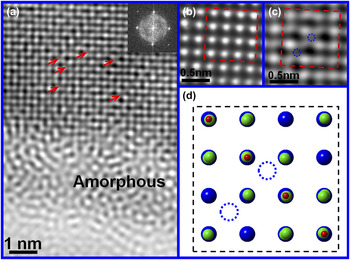
Figure 3(a) and the inset display the HRTEM image and the corresponding FFT pattern viewed along the [001] zone axis from an area around the interface between the outside amorphous surface and the inside ordered ZrC0.6O0.4. In the ordered ZrC0.6O0.4, the oxygen and carbon atoms are located at the centers of Zr-octahedra, and the centers of Zr-tetrahedra are empty. In the HRTEM image shown in Fig. 3(a), however, the Zr-tetrahedral centers are revealed to display the different contrasts. From the ordered ZrC0.6O0.4 inside the powder, an enlarged HRTEM image in Fig. 3(b) shows dark contrast for the empty Zr-tetrahedral centers. As shown in the HRTEM image of Fig. 3(a) and the enlarged one in Fig. 3(c), however, some Zr-tetrahedral centers are imaged in gray in contrast, indicating that they are filled with some kind of atoms. Figure 3(d) gives a crystal model of the rocksalt structured ZrC0.6O0.4 viewed along the [001] zone axis, displaying the occupation of Zr-tetrahedral centers. Considering the low heating temperature of 300 °C, the possibility should be very low for the strong Zr–C bonds to be broken and the released carbon atoms to be replaced with oxygen atoms. Thus, it is most probable that some oxygen atoms are thermally activated to diffuse into the Zr-tetrahedral centers, forming the Zr-tetrahedra similar to those in cubic ZrO or ZrO2. In the previous studies on the oxidation of ZrC via the angle-resolved photoemission spectroscopy and resonant photoemission spectroscopy, Edamoto and coworkers Reference Edamoto, Nagayama, Ozawa and Otani14 reported the formation of a thin layer on ZrC (100) surface with the electronic structure similar to that of ZrO. Rodriguez and coworkers Reference Rodriguez, Liu, Gomes, Nakamura, Viñes, Sousa and Illas13 reported similar results from the high-resolution photoemission and first-principles studies on the interaction of oxygen with ZrC (001). All these reports indicate the presence of oxygen atom centered Zr-tetrahedra, consistent with our observations. In the present case, however, the diffusion of superfluous oxygen atoms into the Zr-tetrahedral centers does not lead to the breaking of Zr–C bonds. With the heating lasting longer, more oxygen atoms will squeeze into the Zr-tetrahedral centers. The Zr-tetrahedra and Zr-octahedra will be severely distorted by the coexistence of the center-occupied Zr-tetrahedra and octahedra. The severe distortions will make the maintenance of the rocksalt structure become difficult. Finally, an amorphous layer of ZrC0.6O y>0.4 is thus induced to form on the powder surface, and the layer thickness is dependent on the heating time. As shown in Fig. 1(a), when the heating time is long enough, an amorphous layer of ∼35 nm is clearly observable in the TEM images. From the observations above, the amorphization on the powder surface at low heating temperature can be attributed to the superfluous oxygen atoms diffusing into the Zr-tetrahedral centers.
(a) The Fourier filtered HRTEM image and the corresponding FFT pattern (inset) viewed along the [001] zone axis from the particle as shown in Fig. 2. The red arrows point out the O-occupied centers of Zr-tetrahedra. (b) The Fourier filtered HRTEM image of an area far away from the particle surface, in which the red dashed rectangle marks out the unit cell of the ordered ZrC0.6O0.4. It can be recognized that the Zr-tetrahedral centers are not filled. (c) The enlarged HRTEM image of a selected part under the amorphous layer in (a). The red dashed rectangle marks out the unit cell of the ordered ZrC0.6O0.4, in which the filled centers of Zr-tetrahedra are labeled out with blue dashed circles. (d) The crystal model of the ordered ZrC0.6O y>0.4 viewed along the [001] zone axis. The blue dashed circles mark out the sites corresponding to those labeled out ones in (c).

B. Transformation of amorphous ZrC0.6O y>0.4 under electron beam irradiation
Interestingly, it is noted that long irradiation of electron beam during the TEM measurements is able to induce transformation of the amorphous thin layer on the powder surface of the ordered ZrC0.6O0.4. Figures 4(a) and 4(b) show the BF and DF TEM images and the SAED pattern from a powder of the ordered ZrC0.6O0.4 obtained after the heating at 300 °C for 1000 min. The presence of an amorphous thin layer is discernable on the powder surface in the TEM images. In the SAED pattern from a selected area including the amorphous layer, it is recognized that the observable diffraction arcs and weak halo rings appear to accompany the sharp parent reflections in the neighbor. The diffraction arcs indicate that some nanocrystals are present inside the amorphous layer of ZrC0.6O y>0.4. With the converged electron beam being focused to a small surface area for 60 s, as shown in the BF and DF TEM images in Figs. 4(c) and 4(d), it is observed that the irradiated small area displays the obvious change in contrast, compared to the surrounding area. Correspondingly, the diffraction arcs become brighter than those before the electron irradiation, and the diffraction halo becomes almost invisible. These observations are suggestive of the transformation of amorphous ZrC0.6O y>0.4 to crystalline zirconia under the electron irradiation.
(a) The BF TEM image of an ordered ZrC0.6O0.4 particle obtained after isothermal heating treatment of the ordered ZrC0.6 at 300 °C for 1000 min. The SAED pattern (inset) was collected along the
 $[\bar 211]$
axis from the marked surface area with a red circle. (b) The DF TEM image of a particle obtained by using one of the diffraction arcs. (c) The BF TEM image of a particle after the exposure to the convergent electron beam irradiation for 60 s. The irradiated area is marked out with a red circle. The SAED pattern (inset) was collected from the marked area. (d) The DF TEM image obtained by using one of the diffraction arcs in SAED pattern. The irradiated area pointed out with a red arrow corresponds to the same area pointed out with a red arrow in (b).

For the ordered ZrC0.6O0.4 with an amorphous ZrC0.6O
y>0.4 layer on the powder surface, which was obtained after the heating at 300 °C for 1000 min, investigations are carried out to explore the transformation of the amorphous ZrC0.6O
y>0.4 under the exposure to irradiation of dispersed electron beam. After the irradiation of 10 min, the DF TEM image and the SAED patterns are taken from the powder along three different zone axes of
 $[\bar 101]$
,
 $[\bar 211]$
and
 $[001]$
and are shown in Fig. 5. In the SAED patterns, the strong parent reflections result from the rocksalt structure of the ordered ZrC0.6O0.4, and the weak superstructural reflections come from the ordered oxygen atoms. Using one of the parent reflections in Fig. 5(d), the obtained DF TEM image in Fig. 5(a) demonstrates that the ordered ZrC0.6O0.4 is preserved as a core inside the powder, in which the oxygen atoms remain ordered. Moreover, in comparison to the ordered ZrC0.6O0.4 before the irradiation, the strong elongated reflections are induced to appear by the electron irradiation, accompanying the parent reflections in the neighbor. These elongated reflections indicate the formation of a crystalline phase with the structure similar to that of the cubic ZrC0.6O0.4. From the SAED patterns viewed along three different zone axes, the irradiation-induced crystalline phase is determined to belong to the space group of Fm3m. For this cubic phase, the calculated unit cell parameter of 0.516 nm is larger than that of the cubic ZrC0.6O0.4 (0.46 nm), but is much close to the cell parameters of cubic ZrO (0.511 nm, ISCD-77713) and cubic ZrO2 (0.513 nm, JCPDS 49-1642). The irradiation-induced crystalline phase is further confirmed via the HRTEM image taken from the surface area along the
 $[\bar 101]$
zone axis and the corresponding FFT pattern. As shown in the HRTEM image of Fig. 6(a) and the enlarged one of Fig. 5(c), some nanocrystals are observed inside the amorphous layer on the powder surface. Moreover, the amorphous layer is ∼10 nm in thickness, much smaller than the observed 35 nm before the irradiation of 10 min (Fig. 1). The great reduction in thickness of the amorphous layer can be attributed to the irradiation-induced transformation from the amorphous phase to the crystalline one. As shown in the HRTEM image of Fig. 6(a) and the enlarged one of Fig. 6(b), a thick crystalline layer is recognized to exist under the amorphous layer, and the FFT pattern [inset in Fig. 6(a)] is similar to the SAED pattern of the ordered ZrC0.6O0.4 along the
 $[\bar 101]$
zone axis. However, the calculated lattice spaces from the marked reflections are 0.258 and 0.301 nm, which are larger than the (020) and (111) lattice spaces of ordered ZrC0.6O0.4, but much close to those of ZrO (ISCD-77713, 0.2555 and 0.295 nm for (020) and (111), respectively) and cubic ZrO2 (JCPDS 49-1642, 0.25645 nm and 0.29646 nm for (020) and (111), respectively). Interestingly, the nanocrystals are identified to show the same orientation as the crystalline oxide layer.
(a) The DF TEM image of the same particle shown in Fig. 4, but it was obtained by using one of the parent reflections of the ordered ZrC0.6O0.4 shown in (d). (b–d) The SAED patterns from the powder along the
 $[\bar 101]$
,
 $[\bar 211]$
and [001] zone axes, respectively.

(a) The Fourier filtered HRTEM image of the same particle shown in Figs. 4 and 5, which was viewed along the
 $[\bar 101]$
zone axis. The inset is the corresponding FFT pattern. Inside the amorphous layer marked out with two red dashed lines, the cubic ZrO2 nanocrystals marked with white dashed circles are observable. (b) The enlarged HRTEM image of the part under the amorphous layer in (a). (c) The enlarged HRTEM image of the surface area in (a), displaying a cubic ZrO2 nanocrystal and the interface between the amorphous layer and the crystalline cubic ZrO2.

When exposure to the dispersed electron irradiation lasts long enough (more than 15 min), the amorphous layer is found to be no longer visible. From a powder of the ordered ZrC0.6O0.4, after the dispersed electron irradiation, the HRTEM images are taken along the [001],
 $[\bar 101]$
and
 $[\bar 211]$
zone axes. Figure 7 shows the HRTEM images and the corresponding FFT patterns. Though the HRTEM images display the observable defects and distortions of the lattice on the powder surface, the corresponding FFT patterns show the features of a single crystal. In Figs. 7(b) and 7(d), some weak reflections can be observed in addition to the fundamental reflections corresponding to cubic ZrO2−x. These weak reflections may be originated from the appearance of forbidden reflections of cubic ZrO2−x
induced by the lattices distortions.
(a, c, and e) The Fourier filtered HRTEM images of the same particle shown in Figs. 4–6 along three different zone axes [001] (a and b),
 $[\bar 101]$
(c and d) and
 $[\bar 211]$
, respectively. The powder was exposed to the irradiation of dispersed electron beam for ∼15 min before the HRTEM measurements. (b, d, and f) The FFT patterns corresponding to the HRTEM images in (a, c, and e), respectively. They demonstrate the good crystallinity of the irradiation-produced ZrO2−x
layer on the powder surface.

In the transformation of amorphous ZrC0.6O y>0.4 to crystalline zirconia under the irradiation of electron beam, strong dependence on the irradiation dose and time has been observed. For the electron beam focused on a local small area, the irradiation dose can reach a high level in a short time such that the transformation is induced to occur. In this case, the focused irradiation is able to quickly raise the temperature in the local small area. Thereby, the role of the heating effect can not be ruled out in the transformation of amorphous ZrC0.6O y>0.4 to crystalline zirconia. For a large area under the dispersed irradiation of the electron beam, a long irradiation time is necessary for the transformation to occur. The heating effect of dispersed irradiation should be much weaker than that of the focused beam. In the case of dispersed irradiation of the electron beam, though the heating effect can not be completely ruled out, it should not be the key role in the observed transformation. Generally, the electron irradiation can produce the structural damages such as extended defects Reference Reyes-Gasga and García-García23–Reference Teweldebrhan and Balandin25 and even amorphous phase Reference Thomas, Mori, Fujita and Sinclair26–Reference Okamoto, Lam and Rein28 in crystalline materials. However, recent studies Reference Jenčič, Bench, Robertson and Kirk29–Reference Miyao, Polman, Sinke, Saris and van Kemp32 have revealed that the crystallization can also be initiated in amorphous materials at relatively low temperatures by the irradiation of electron or other ion beams. It has been pointed out that the crystallization results mainly from the knock-on effect and/or electronic excitations instead of the beam heating effect. Reference Frantz, Tarus, Nordlund and Keinonen33–Reference Nagase and Umakoshi35 Owing to the epitaxial features of irradiation-induced crystalline phase with respect to the substrate, the crystallization process is named as electron beam induced epitaxial crystallization (EBIEC) or ion beam induced epitaxial crystallization (IBIEC). EBIEC and IBIEC have been observed in many amorphous materials, such as Si, Ge, GaP, GaAs, Reference Jenčič, Bench, Robertson and Kirk29–Reference Elliman, William, Maher and Brown31 metallic glasses, Reference Nagase and Umakoshi35,Reference Nagase, Nino and Umakoshi36 etc. Electron beam induced crystallization of amorphous zirconia film deposited on the SiO2 substrate was also reported by Roddatis and coworkers.37 In the transformation of the amorphous ZrC0.6O y>0.4 layer to a crystalline cubic ZrO2−x one under the dispersed electron irradiation, though it is different from the previously reported EBIEC or IBIEC, it has been considered that the knock-on effect and/or electronic excitations under the electron irradiation should play the dominant role.
C. In situ EELS observations of transformation of amorphous ZrC0.6O y>0.4
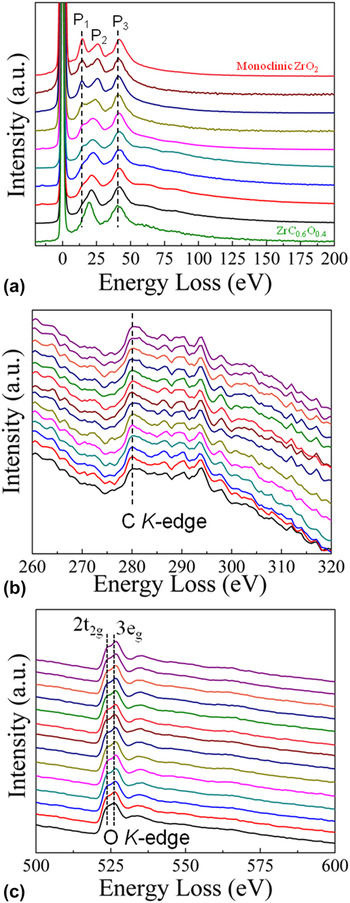
In situ EELS were collected to investigate the transformation process of the amorphous ZrC0.6O y>0.4 layer. The EELS are recorded in image mode from a powder of the ordered ZrC0.6O0.4 obtained after the 1000 min heating at 300 °C, and a dispersion of 0.5 eV/ch and a 2 mm entry aperture are chosen. The electron beam is converged to a spot of ∼50 nm in diameter and is focused to a selected amorphous area. The EELS are collected during the continuous exposure to this converged irradiation. Figure 8(a) shows the low loss section of EELS. As references, the EELS are also measured for the ordered ZrC0.6O0.4 and the monoclinic ZrO2−x . The peak labeled as P2 is attributed to the bulk plasma. The predominant peak around 41.7 eV (P3) is attributed to an excitation of the Zr 4p level to a level of 11 eV above E F. Reference Grunes, Leapman, Wilker, Hoffmann and Kunz38 This peak displays no obvious change during the irradiation process. The energy loss peak at ∼14 eV (P1) is associated with a transition between the oxygen 2p and 3s levels. In the beginning of irradiation, the recorded EELS are similar to that of the ordered ZrC0.6O0.4, but different from that of monoclinic ZrO2. As shown in Fig. 8(a), the energy loss peak at 14 eV exhibits the fast change under the sustaining convergent irradiation. After the continuous irradiation of just 60 s, the energy loss peak at ∼14 eV is completely separated out, and the EELS become similar to that of the monoclinic ZrO2. No more obvious change in EELS can be observed with prolonged irradiation time. The further more irradiation no longer leads to any obvious change in the EELS. Thus, the electron beam irradiation is demonstrated to induce the transformation of amorphous ZrC0.6O y>0.4 to crystalline oxide of ZrO2−x . Figures 8(b) and 8(c) show the recorded C and O K-edges, respectively, from two different areas of the amorphous layer. The C K-edge is always visible during the continuous irradiation. This indicates that during the irradiation-induced transformation process, the Zr–C bonds are broken, but the released C atoms are retained in the lattice of ZrO2−x , most probably as the interstitial impurities. The presence of the interstitial C impurities probably favors the stability of the observed cubic ZrO2−x . Reference Wang, Luo, Soo, Sabirianov, Lin, Mei, Namavar and Cheung39 As shown in Fig. 8(c), the two peaks corresponding to the 2t2g and 3eg of O K-edge are quickly separated out from each other with the continuous irradiation. These changes in the O K-edge can be ascribed to the transformation of amorphous ZrC0.6O y>0.4 to crystalline oxide of cubic ZrO2–x . Reference Grunes, Leapman, Wilker, Hoffmann and Kunz38
(a) The low energy loss section of EELS for the ordered ZrC0.6O0.4 (the bottom one), the monoclinic ZrO2−x (the top one), and the amorphous layer of ZrC0.6O y>0.4 (the ones between bottom and top). In the EELS measurements, the used powder of the ordered ZrC0.6O0.4 was obtained with isothermally heating treatment of the ordered ZrC0.6 at 300 °C in air for 1000 min. The electron beam was converged into a spot of ∼50 nm and focused to a small area in the amorphous layer. The small area was exposed to the sustaining irradiation of the convergent electron beam spot. During the continuous irradiation, the collection of EELS was performed from the same area after every 10 s exposure. (b) The recorded C K-edge after every 10 s exposure to the focused irradiation. (c) The recorded O K-edge after every 10 s exposure to the focused irradiation.

In comparison to the irradiation during the TEM measurements, the irradiation dose is much higher under the exposure to a convergent electron beam during the EELS recording. Based on the in situ EELS observations, it can be found that the transformation of amorphous ZrC0.6O y>0.4 to crystalline cubic zirconia is very quick, and it can be finished within ∼60 s. Considering the required long annealing time for the formation of the amorphous layer, such quick transformation can not be only attributed to the beam heating effect. It was reported that the knock-on effect and/or electronic excitations should be dominant in the crystallization process. Reference Frantz, Tarus, Nordlund and Keinonen33–Reference Nagase and Umakoshi35 Those effects are associated with the energy of incident electron beam, threshold energy of atoms, temperature, and impurity in sample. In the amorphous layer of ZrC0.6O y>0.4, C and O atoms keep bonding with Zr atoms. C atom has a threshold energy of about 25 eV, lower than those of Zr (80–120 eV) Reference Gosset, Dollé, Simeone, Baldinozzi and Thomé40 and O (50 eV), Reference Edmondson, Weber, Namavar and Zhang41 though they exhibit slightly different values in different materials. The electron irradiation is able to induce the displacement of atom, thus leading to the breaking of bonds. Reference Corticelli, Lulli and Meili30 Thereby, it is reasonable to speculate that in comparison to Zr and O atoms, the displacement of C atom can be easily induced to occur under the exposure to electron irradiation with energy and dose high enough, thus resulting in the breaking of Zr–C bonds. On the other hand, the amorphous ZrC0.6O y>0.4 is metastable owing to the coexistence of Zr–C and Zr–O bonds. The transformation of the amorphous ZrC0.6O y>0.4 layer to a crystalline oxide layer should start from the breaking of Zr–C bonds at the interface between the amorphous layer and the underlying ordered ZrC0.6O0.4, finally producing a crystalline layer of cubic ZrO2−x .
IV. CONCLUSIONS
In summary, for the ordered ZrC0.6O0.4 obtained via the isothermal heating at low temperatures, it is found that an amorphous layer of ZrC0.6O y>0.4 can be formed on the powder surface, depending on the heating time. The formation of amorphous ZrC0.6O y>0.4 during the heating treatment can be attributed to the diffusion of superfluous oxygen atoms into the surface area. It is observed that the superfluous oxygen atoms are thermally activated to squeeze into the centers of Zr-tetrahedra. The coexistence of the Zr-tetrahedra and Zr-octahedra with the occupied centers can lead to the severe distortion of the lattice, producing the observed amorphous layer of ZrC0.6O y>0.4. Under the exposure to the electron beam irradiation, it is noted that the amorphous ZrC0.6O y>0.4 can transform to the crystalline oxide of cubic ZrO2−x . This transformation process is investigated via in situ observations of (HR) TEM images, SAED patterns, and EELS. Under the exposure to electron beam irradiation, transformation of the amorphous ZrC0.6O y>0.4 layer is induced to occur, producing a crystalline oxide layer of cubic ZrO2−x with the same orientation as the underlying ordered ZrC0.6O0.4. During the transformation process, the Zr–C bonds are broken due to the knock-on effect and/or electronic excitations. The released C atoms are retained in the oxide lattice as the interstitial impurities, probably favoring the stability of the cubic ZrO2−x .
Supplementary Material
To view supplementary material for this article, please visit http://dx.doi.org/jmr.2015.386.
The XRD patterns of the vacancy-ordered ZrC0.6 and the samples obtained after isothermal heating treatments of the ordered ZrC0.6 at two different temperatures (Fig. S1).
ACKNOWLEDGMENT
We would like to thank the financial supports from the Doctoral Fund Project of Yanshan University (B905).