1. Introduction
A typical parallel manipulator is made of a fixed platform and a moving platform in-parallel connection by several legs or limbs. Due to their closed-loop architectures, only a subset of the mechanism joints is actuated allowing for a full control of the parallel manipulator. The combination of low inertia, accuracy, and high stiffness allowed parallel manipulators to be successfully used in several applications ranging from seminal flight simulators to high-speed pick-and-place and haptic devices. In that concern, the Adept Quattro, a commercially available four-legged parallel manipulator, is the world’s fastest packaging robot. Despite their successful applications in both academic and industrial sectors, shortcomings of parallel manipulators such as their limited workspace, poor manipulability, and the presence of recurrent singularities have been extensively discussed in the literature. Hence, in recent years, parallel manipulators with configurable platforms, a kind of robots closer to the so-called metamorphic or deployable mechanisms [Reference Wang, Yao and Kong1, Reference Huang, Guo, Zhang, Qu and Tang2, Reference Han, Zheng, Xu, Yao and Zhao3], have been introduced as an option to ameliorate the drawbacks of parallel manipulators with rigid moving platforms [Reference Mohamed and Gosselin4, Reference Lambert and Herder5, Reference Hoevenaars, Gosselin, Lambert and Herder6, Reference Tian, Zhang, Tang and Chenwei7]. Parallel manipulators with configurable moving platforms are a different type of architecture in which the classical moving platform is replaced by a novel closed-loop kinematic chain introducing internal o extra degrees of freedom to the parallel manipulator. More than an academic curiosity, the inclusion of a configurable platform offers interesting advantages, e.g., the internal mobility of the configurable platform allows for an interaction with the environment from multiple contact points. Furthermore, the increased mobility of the configurable platform may be used to avoid or to escape from singular configurations. The first contribution to glimpse this type of manipulators was published at the beginning of the 21st century [Reference Yi, Na, Lee, Hong, Oh, Suh and Kim8] where a configurable platform is proposed as a gripper. Few years later, a generalization of the concept was introduced in ref. [Reference Mohamed and Gosselin4]. Following these seminal papers, the concept of configurable platform was applied in well-known parallel manipulators such as the Delta robot [Reference Pfurner9] and the Gough-Stewart platform [Reference Gallardo-Alvarado10].
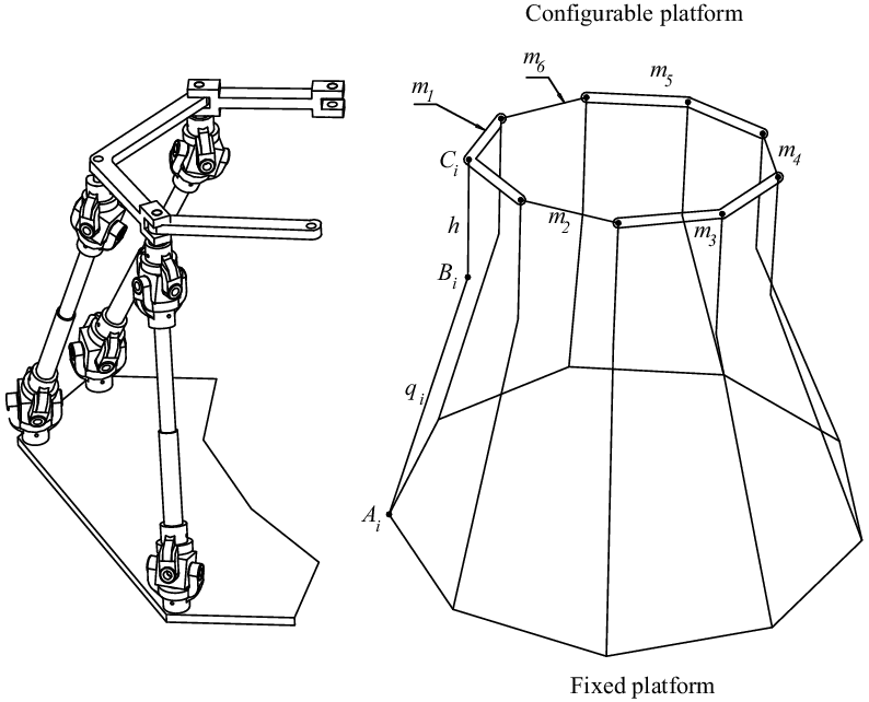
Parallel manipulator with configurable platform.

In this work, a nine-legged in-parallel manipulator with configurable platform is introduced with the purpose to control the position of three points of the configurable platform. The chosen points are located on different links of the configurable platform, so that the three points form a grasping triangle. The closure equations of the inverse-forward position analyses are established taking into account the motion constraints of the configurable platform as well as the symmetric topology of the limbs. While the inverse position analysis equations lead to a closed form solution that yields a unique solution, the direct position analysis is a more challenging task which leads to 27 or 18 nonlinear equations that are solved by means of the Newton-homotopy method. On the other hand, the infinitesimal kinematics of the proposed robot is approached by means of the theory of screws. Finally, the reliability of the method of kinematic analysis introduced in the contribution is proved with numerical examples covering most of the topics treated in the contribution.
2. Description of the parallel manipulator with configurable platform
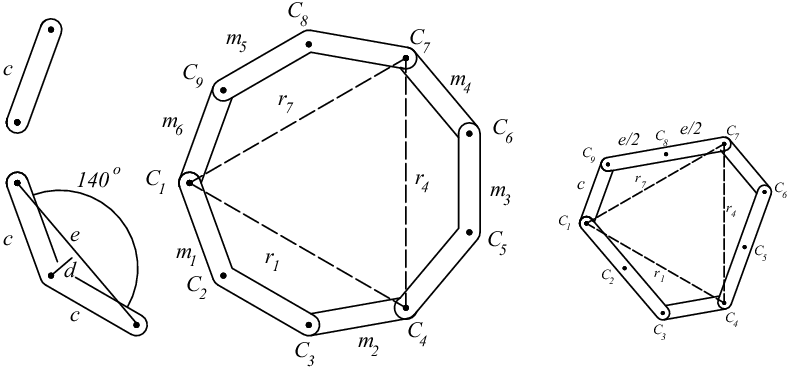
The proposed robot, see Fig. 1, consists of a fixed platform in-parallel connection with a configurable moving platform by means of nine limbs with identical topologies. Two architectures are contemplated for the configurable platform, see Fig. 2. In order to explain the geometry of the robot, let us consider that
 $O\_XYZ$
is a reference frame attached to the center
 $O$
of the fixed platform where the
 $Z-$
axis is normal to the plane of the fixed platform. The fixed platform shapes a regular nonagon of side
 $a$
where their vertices are notated by points
 $A_i$
that are located by vectors
 ${{\textbf{a}}}_i$
. Unless otherwise stated, in the rest of the contribution
 $i=1,2,3,\ldots,9$
. The
 $i-$
th limb is assembled to the fixed platform by means of a lower universal joint U whose axes intersect at point
 $A_i$
. Following the lower universal joint, there is an actuated prismatic joint
 $\underline{\rm P}$
which ends in an upper universal joint whose axes intersect at point
 $B_i$
which is located by vector
 ${{\textbf{b}}}_i$
. With the purpose to simulate a spherical joint, a revolute joint R follows the upper universal joint. Hence, the legs of the robot are of the U
 $\underline{\rm P}$
UR-type. Finally, the limbs of the robot are connected to the configurable platform by means of revolute joints whose nominal positions are denoted by points
 $C_i$
that are located by vectors
 ${\textbf{c}}_i$
. In order to realize the mechanical assembly, there is an offset
 $h$
between the links of the configurable platform and the corresponding upper universal joints. On the other hand, the configurable platform shapes an hexagon able to change its contour. That is, unlike the typical rigid platform, the configurable platform of the robot is able to modify the geometry of its contour. Three binary links, labeled
 $m_i(i=2,4,6)$
, and three ternary links, labeled
 $m_i(i=1,3,5)$
, in series connection in an alternating manner make up the configurable platform. Indeed, the 6
 $\bar{\textrm{R}}$
configurable platform provides three internal degrees of freedom to the robot where
 $\bar{\textrm{R}}$
denotes the revolute joint connecting a binary link with a ternary link of the configurable platform. With this in mind, for brevity, the proposed robot is designated as a 9-U
 $\underline{\rm P}$
UR{6R} parallel manipulator where the braces denote the revolute joints of the configurable platform.
Topology of the configurable platform. Bent ternary links and straight ternary links.

The mobility of the mechanism can be explained without necessarily a deep mathematical rigor by separating the mobility of the robot into the mobility of the configurable platform and adding the mobility of the manipulator as if it were a conventional 9-UPUR parallel manipulator provided with a rigid platform. The mobility of the configurable platform is computed taking into account that the revolute joints lie in the plane of the configurable platform. That is, the axes of the revolute joints are parallel. It is therefore understandable to assume that the assembly of the links is such that the movement of the links is limited to being in-parallel planes, to form what is known as a planar coupling. In such a case, the degrees of freedom of the links of the configurable platform are three instead of six due to the constraints imposed by the joints. Hence, the mobility
 $Ma$
of the configurable platform is computed by resorting to the Chebychev–Grübler–Kutzbach criterion as
 $M=3(N-1-j)+\sum _{i=1}^i f_i$
where
 $N=6$
is the number of links,
 $j=6$
is the number of kinematic pairs, and
 $\sum _{i=1}^i f_i=6$
is the sum of the degrees of freedom of the kinematic pairs. Thus, one obtains
 $Ma=3$
. On the other hand, the mobility
 $Mb$
of the conventional 9-UPUR parallel manipulator is determined taking into account in this case that the Chebychev–Grübler–Kutzbach criterion is given by
 $Mb=6(N-1-j)+\sum _{i=1}^i f_i$
where
 $N=29$
,
 $j=36$
, and
 $\sum _{i=1}^i f_i=54$
which yields
 $Mb=6$
. Afterward, it concludes that the 9-UPUR{R} parallel manipulator with configurable platform is capable of supporting nine degrees of freedom. This gives us the opportunity of having nine active kinematic pairs, the prismatic joints are the natural option, with which it is possible to perform tasks under different operating modes of the robot. For example, one could select a link of the configurable platform as the end-effector and then one could control the position and orientation of the end-effector and still have three additional degrees of freedom. This concept of extra freedoms is known as actuation redundancy and was introduced in refs. [Reference Merlet11, Reference Wang and Gosselin12]. Actuation redundancy does not modify the mobility of the robot but enriches it with more actuators than necessary to carry out the tasks entrusted to it. The extra motors may be used for instance to reduce the singularities within the workspace of the manipulator. The idea of the contribution is not to introduce a parallel manipulator with actuation redundancy but to take advantage of the nine degrees of freedom of the robot in a configurable platform. To this end, the conventional rigid moving platform is replaced by a 6-R planar closed kinematic chain in which ternary and binary links are articulated alternately. Once the mobility of the mechanism has been justified, the application of the degrees of freedom and the selection of the active kinematic pairs of it are the next natural steps. Undoubtedly, the choice of the nine prismatic pairs as the active kinematic pairs is the best option. On the other hand, the choice of three points located in different links of the configurable platform complements this reasonable conjugation of degrees of freedom and where to apply them. These points form what is called a grasping triangle. Moreover, the points where motion is shared between ternary and binary links are selected as the vertices of the grasping. In that sense, it is appropriate to recognize that while it is true that the inverse and direct kinematics of the triangle are perfectly controllable by the combined action of the prismatic joints, the links of the configurable platform will undergo parasitic rotations. Owing to the in-parallel arrangement of the proposed robot, unlike the contribution introduced in ref. [Reference Gallardo-Alvarado10], conveniently the nine prismatic joints of the parallel manipulator under study are actuated and therefore all the motors of it are mounted near to the fixed platform.
3. Displacement analysis
The position analysis of parallel manipulators, especially the direct position analysis, has been a topic of great relevance for most kinematicians. The subject has attracted the attention of mathematicians and engineers alike with the aim of developing efficient methods of analysis as well as improving existing methods. The number of contributions that address the subject is remarkable, yet it remains an open problem of great interest given its importance in the control of robots with topologically parallel kinematic chains. Given the recent inclusion of parallel manipulators with configurable platforms, the position analysis of these novel mechanisms will surely be a topic of growing interest owing to the challenges it represents. In this section, the inverse and forward displacement analyses of the robot under study are approached by resorting to simple algebraic geometry. The merits of the section can be summarized in how easy and systematically are obtained the closure equations.
3.1. Inverse position analysis
The inverse position analysis is based on the computation of the generalized coordinates
 $q_i(i=1,2,3,\ldots,9)$
that meet a specific configuration of the grasping triangle
 $\triangle C_1C_4C_7$
. In other words, given the coordinates of the vertices of the grasping triangle, the points
 $C_1$
,
 $C_4$
, and
 $C_7$
; it is required to determine the generalized coordinates
 $q_i(i=1,2,3,\ldots,9)$
that satisfy the given configuration. The configurable platform composed of bent ternary links is considered first. For this purpose, the inverse position analysis is based on dividing the geometry of the configurable platform into three polygons. For example, one polygon is shaped with the points
 $C_1$
,
 $C_2$
,
 $C_3$
, and
 $C_4$
.
As an initial step, it is evident that if the coordinates of the points
 $C_1$
,
 $C_4$
, and
 $C_7$
are known, then the unit vector
 $\hat{{\textbf{n}}}$
normal to the plane of the triangle
 $\triangle C_1C_4C_7$
, named the grasping triangle, is determined directly as follows:
 \begin{equation} \hat{{\textbf{n}}}=\frac{ ({\textbf{c}}_4 -{\textbf{c}}_1) \times ({\textbf{c}}_7 -{\textbf{c}}_1)}{ \mid ({\textbf{c}}_4 -{\textbf{c}}_1) \times ({\textbf{c}}_7 -{\textbf{c}}_1) \mid } \end{equation}
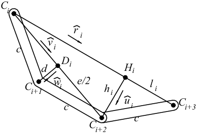
Geometry of the
 $i-$
th polygon of the configurable platform.

The inverse position analysis is first focused on the calculation of the coordinates of points
 $C_{i+1}$
and
 $C_{i+2}$
, see Fig. 3, of each one of the three polygons. From the triangle
 $\triangle C_iC_{i+2}C_{i+3}$
, two closure equations are generated as follows:
 \begin{equation} e^2-c^2-r_i^2+2r_il_i=0, \quad h_i^2-c^2+l_i^2=0 \end{equation}
which allow us to calculate the values of
 $h_i$
and
 $l_i$
. Thereafter, the vector
 ${{\textbf{h}}}_i$
denoting the position of point
 $H_i$
is computed as
 \begin{equation} {\textbf{h}}_i={\textbf{c}}_i+(r_i-l_i) \hat{{\textbf{r}}}_i \end{equation}
where
 $ \hat{{\textbf{r}}}_i$
is a unit vector pointed from point
 $C_i$
to point
 $C_{i+3}$
. Following this natural sequence, the vector
 ${\textbf{c}}_{i+2}$
turns out to be
 \begin{equation}{\textbf{c}}_{i+2}={{\textbf{h}}}_i+h_i \hat{{\textbf{u}}}_i \end{equation}
where
 $\hat{{\textbf{u}}}_i$
is a unit vector normal to the vectors
 $\hat{{\textbf{r}}}_i$
and
 $\hat{{\textbf{n}}}$
. That is,
 \begin{equation} \hat{{\textbf{u}}}_i=\hat{{\textbf{r}}}_i \times \hat{{\textbf{n}}} \end{equation}
On the other hand, the vector
 ${\textbf{c}}_{i+2}$
is computed taking into account that the vector
 ${{\textbf{d}}}_i$
is given by
 \begin{equation}{{\textbf{d}}}_i=({\textbf{c}}_i+{\textbf{c}}_{i+2})/2 \end{equation}
Hence,
 \begin{equation}{\textbf{c}}_{i+1}={{\textbf{d}}}_i+d \hat{{\textbf{w}}}_i \end{equation}
Therein,
 $\hat{{\textbf{w}}}_i$
is a unit vector normal to the unit vectors
 $\hat{{\textbf{v}}}_i$
, pointed from point
 $C_i$
to point
 $C_{i+2}$
, and
 $\hat{{\textbf{n}}}$
. That is,
 \begin{equation} \hat{{\textbf{w}}}_i=\hat{{\textbf{v}}}_i \times \hat{{\textbf{n}}} \end{equation}
Once the procedure is applied to each one of the three polygons, the vectors
 ${{\textbf{b}}}_i(i=1,2,3,\ldots,9)$
are computed as follows:
 \begin{equation}{{\textbf{b}}}_i={\textbf{c}}_i- h \hat{{\textbf{n}}} \quad i=1,2,3,\ldots,9 \end{equation}
Finally, the generalized coordinates
 $q_i(i=1,2,3,\ldots,9)$
meeting the conditions imposed to the grasping triangle are calculated as follows:
 \begin{equation} q_i^2=({{\textbf{b}}}_i-{{\textbf{a}}}_i) \cdot ({{\textbf{b}}}_i-{{\textbf{a}}}_i) \quad i=1,2,3,\ldots,9 \end{equation}
The method outlined in the contribution for solving the inverse position analysis is easy to follow and allows to obtain a closed-form solution of it with a unique solution. In other words, given the coordinates of points
 $C_i$
, there is only one solution for the inverse position analysis of the robot. Furthermore, once the inverse position analysis of the robot with configurable platform composed of bent ternary links was achieved, the inverse position analysis of the robot with configurable platform composed of straight links is straightforward.
3.2. Forward position analysis
The direct position analysis consists of determining the coordinates of the points
 $C_i(i=1,2,3,\ldots,9)$
of the configurable platform given a set of generalized coordinates
 $q_i$
. To this end, in addition to the closure equations introduced for the inverse position analysis, it is possible to consider additional closure equations that allow us to formulate the forward position analysis. The analysis is dedicated first to the robot with configurable platform composed of bent ternary links. To this end, for simplicity consider the polygon
 $C_1C_2C_3C_4$
.
From the parameters
 $c$
,
 $d$
, and
 $e$
, three closure equations will be given by
 \begin{equation} ({\textbf{c}}_4-{\textbf{c}}_3) \cdot ({\textbf{c}}_4-{\textbf{c}}_3)=c^2, \quad ({\textbf{c}}_2-{\textbf{c}}_1) \cdot ({\textbf{c}}_2-{\textbf{c}}_1)=d^2, \quad \text{and} \quad ({\textbf{c}}_3-{\textbf{c}}_1) \cdot ({\textbf{c}}_3-{\textbf{c}}_1)=e^2 \end{equation}
It is straightforward to show that similar expressions to (11) can be obtained from the polygons
 $C_4C_5C_6C_7$
and
 $C_7C_8C_9C_1$
. On the other hand, since the points
 $C_i$
lie in the same plane, then from the orthogonality condition between the vector
 ${\textbf{n}}$
and the plane of the configurable platform it follows that
 \begin{equation} ({\textbf{c}}_{i+1}-{\textbf{c}}_i) \cdot{{\textbf{n}}}=0, \quad i=1,2,3,\ldots, 9 \end{equation}
where
 ${\textbf{c}}_{10}={\textbf{c}}_1$
. Meanwhile, assuming that
 $h=0$
, then
 ${{\textbf{b}}}_i={\textbf{c}}_i$
which implies that from the generalized coordinates
 $q_i$
we obtain that
 \begin{equation} ({\textbf{c}}_i-{{\textbf{a}}}_i) \cdot ({\textbf{c}}_i-{{\textbf{a}}}_i)=q_i^2 \end{equation}
The algorithm for solving the direct position analysis consists of the following steps:
-
1. Write the nine points
 $C_i$
in terms of unknown coordinates
$w_i(i=1,2,3,\ldots,27)$
to be determined
$C_1=(w_1,w_2,w_3)$
,
$C_2=(w_4,w_5,w_6)$
,
$\cdots$
,
$C_9=(w_{25},w_{26},w_{27})$
.
-
2. Symbolically compute the vector
${\textbf{n}}$
, e.g.,
${{\textbf{n}}}=({\textbf{c}}_4 -{\textbf{c}}_1) \times ({\textbf{c}}_7 -{\textbf{c}}_1)$
. -
3. Generate nine quadratic equations based on expressions (11).
-
4. Write nine quadratic equations from Eq. (12).
-
5. Generate nine quadratic equations by resorting to Eq. (13).


Dealing with the robot whose configurable platform is composed of straight ternary links, the forward displacement analysis can be performed in a simpler way. Indeed, key points
 $C_*$
of the configurable platform may be expressed in terms of unknown coordinates
 $w_*$
as follows
 $C_1=(w_1,w_2,w_3)$
,
 $C_3=(w_4,w_5,w_6)$
,
 $C_4=(w_7,w_8,w_9)$
,
 $C_6=(w_{10},w_{11},w_{12})$
,
 $C_7=(w_{13},w_{14},w_{15})$
, and
 $C_9=(w_{16},w_{17},w_{18})$
. Afterward, the points
 $C_2$
,
 $C_5$
, and
 $C_8$
located at the middle of their corresponding ternary links can be expressed as
 \begin{equation} C_2=(C_1+C_3)/2, \quad C_5=(C_4+C_6)/2, \quad \text{and} \quad C_8=(C_7+C_9)/2 \end{equation}
Six closure equations are written based on the separations of the revolute joints as follows:
 \begin{align} ({\textbf{c}}_3-{\textbf{c}}_1) \cdot ({\textbf{c}}_3-{\textbf{c}}_1) &=e^2, ({\textbf{c}}_4-{\textbf{c}}_3) \cdot ({\textbf{c}}_4-{\textbf{c}}_3)=c^2, \nonumber \\[5pt] ({\textbf{c}}_6-{\textbf{c}}_4) \cdot ({\textbf{c}}_6-{\textbf{c}}_4) &=e^2, ({\textbf{c}}_7-{\textbf{c}}_6) \cdot ({\textbf{c}}_7-{\textbf{c}}_6)=c^2, \nonumber \\[5pt] ({\textbf{c}}_9-{\textbf{c}}_7) \cdot ({\textbf{c}}_9-{\textbf{c}}_7)&=e^2, ({\textbf{c}}_1-{\textbf{c}}_9) \cdot ({\textbf{c}}_1-{\textbf{c}}_9)=c^2, \end{align}
where the shape of the ternary links
 $e=2 c \cos 20^{\circ}$
. Furthermore, due to the planar condition of the configurable platform, it follows that
 \begin{equation} ({\textbf{c}}_9-{\textbf{c}}_1) \cdot \hat{{\textbf{n}}}=0, \quad ({\textbf{c}}_4-{\textbf{c}}_3) \cdot \hat{{\textbf{n}}}=0, \quad ({\textbf{c}}_7-{\textbf{c}}_6) \cdot \hat{{\textbf{n}}}=0, \end{equation}
The eighteen closure equations required to find the unknowns
 $w_i(i=1,2,3,\ldots,18)$
may be completed considering that
 $h=0$
. Thereafter, one can resort to Eq. (13) to achieve this task.
Finally, the reduction of the 27 or 18 nonlinear equations generated in the forward position analysis into a univariate polynomial equation is a formidable and perhaps unrealistic task that beyond the scope of the contribution. Hence, for the sake of completeness in the contribution, the Newton-homotopy method [Reference Wu13, Reference Gallardo-Alvarado14] is employed to numerically find some solutions of the forward position analysis.
4. Infinitesimal kinematics
The mathematical tool selected to perform the infinitesimal kinematics of the robot is the theory of screws [Reference Gallardo-Alvarado15]. The vector properties of velocity of the rigid body can be summarized in the so-called velocity state or twist about a screw of Ball. This kinematic entity, defined as
 ${{\textbf{V}}}_*=\begin{bmatrix}{{\boldsymbol\omega} } \\ {{\textbf{v}}}_* \end{bmatrix}$
, is a vector formed by the concatenation of two vectors: the angular velocity vector
 ${\boldsymbol\omega}$
, named the primal part of
 ${{\textbf{V}}}_*$
, and the velocity vector of a point
 $*$
, named the dual part
 ${{\textbf{V}}}_*$
, of the rigid body. The point
 $O$
is designated as the reference pole. On the other hand, the vector properties of acceleration of the rigid body maybe expressed in the so-called acceleration state
 ${{\textbf{A}}}_*$
of Brand which is defined according to the angular acceleration vector
 ${\boldsymbol\alpha}$
of the body and the acceleration vector
 ${{\textbf{a}}}_*$
of the reference pole
 $*$
as
 ${{\textbf{A}}}_*=\begin{bmatrix}{{\boldsymbol\alpha} } \\ {{\textbf{a}}}_*-{{\boldsymbol\omega} } \times{{\textbf{v}}}_* \end{bmatrix}$
. The vector
 ${\boldsymbol\alpha}$
is named the primal part of
 ${{\textbf{A}}}_*$
, whereas
 ${{\textbf{a}}}_*-{{\boldsymbol\omega} } \times{{\textbf{v}}}_*$
is named the dual part of
 ${{\textbf{A}}}_*$
. Both the velocity and acceleration states of the rigid body are governed by the rules of helicoidal vector fields [Reference Gallardo and Rico16]. Since the representation of the kinematic states is not unique but depends on the point of the body under consideration then according to the properties of helical fields, it is possible to relate the kinematic states of two points
 $P$
and
 $Q$
of the rigid body as follows:
 \begin{equation}{{\textbf{V}}}_Q=\begin{bmatrix} P({{\textbf{V}}}_P) \\[5pt] D({{\textbf{V}}}_P)+ P({{\textbf{V}}}_P) \times{{\textbf{r}}}_{Q/P} \end{bmatrix}, \quad{{\textbf{A}}}_Q=\begin{bmatrix} P({{\textbf{A}}}_P) \\[5pt] D({{\textbf{A}}}_P)+ P({{\textbf{A}}}_P) \times{{\textbf{r}}}_{Q/P} \end{bmatrix} \end{equation}
where
 ${{\textbf{V}}}_P= \begin{bmatrix} P({{\textbf{V}}}_P) \\ D({{\textbf{V}}}_P) \end{bmatrix}= \begin{bmatrix}{{\boldsymbol\omega} } \\ {{\textbf{v}}}_P \end{bmatrix}$
while
 ${{\textbf{A}}}_P= \begin{bmatrix} P({{\textbf{A}}}_P) \\ D({{\textbf{A}}}_P) \end{bmatrix}= \begin{bmatrix}{{\boldsymbol\alpha} } \\ {{\textbf{a}}}_P-{{\boldsymbol\omega} } \times{{\textbf{v}}}_P \end{bmatrix}$
. Furthermore,
 ${{\textbf{r}}}_{Q/P}$
is the position vector of point
 $Q$
with respect to point
 $P$
.
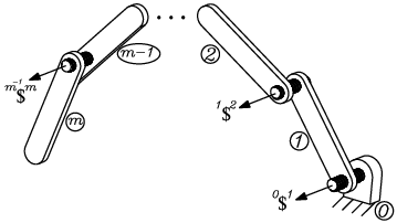
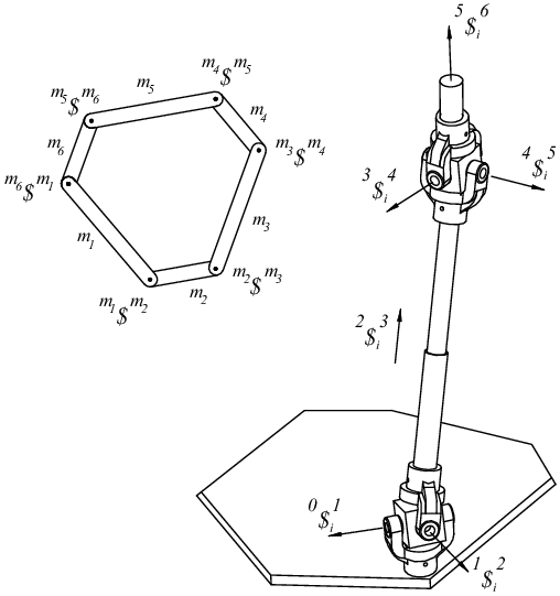
Open kinematic chain and its infinitesimal screws.

Figure 4 shows and open kinematic chain where
 $0$
denotes the fixed link while
 $m$
represents the terminal link. The velocity state of body
 $m$
as measured from body
 $0$
taking point
 $O$
as the reference pole may be expressed in screw form as follows:
 \begin{align}{^0{{\textbf{V}}}_O^m}&=\begin{bmatrix}{^0{{\boldsymbol\omega} }^m} \\[5pt] {{\textbf{v}}}_O \end{bmatrix} \nonumber \\[5pt] &={_0\omega _1}{^0\$^1}+{_1\omega _2}{^1\$^2}+\cdots +{_{m-2}\omega _{m-1}}{^{m-2}\$^{m-1}}+{_{m-1}\omega _m}{^{m-1}\$^m} \end{align}
where
 $_{k}\omega _{k+1}$
is the joint rate velocity between two adjacent bodies
 $k$
and
 $k+1$
. Meanwhile,
 $^k\$^{k+1}$
is the infinitesimal screw associated to the kinematic pair between adjacent bodies
 $k$
and
 $k+1$
. For brevity, the reference pole is not indicated on the screw
 ${\$}$
; however, it is understood that its calculation is achieved considering point
 $O$
as the reference pole. Any kinematic pair can be represented either by an infinitesimal screw or by the conjugate action of a set of screws, hence the universality and versatility of Eq. (18). After the successful representation in screw form of the velocity state of Ball, the derivation of the equation in screw form of the acceleration state of Brand took several decades for its correct mathematical structuring thanks to the contribution of Rico and Duffy [Reference Rico-Martinez and Duffy17]. After some anger and resistance in the kinematic community, this six-dimensional vector was finally established an accepted as follows:
 \begin{align}{^0{{\textbf{A}}}_O^m}&=\begin{bmatrix}{^0{{\boldsymbol\alpha} }^m} \\[5pt] {{\textbf{a}}}_O-{^0{{\boldsymbol\omega} }^m} \times{{\textbf{v}}}_O \end{bmatrix} \nonumber \\[5pt] &={_0\alpha _1}{^0\$^1}+{_1\alpha _2}{^1\$^2}+\cdots +{_{m-2}\alpha _{m-1}}{^{m-2}\$^{m-1}}+{_{m-1}\alpha _m}{^{m-1}\$^m}+{{\textbf{S}}} \end{align}
where
 ${_k\alpha _{k+1}}=\dfrac{d}{dt}{_k\omega _{k+1}}$
is the joint rate acceleration between adjacent bodies
 $k$
and
 $k+1$
of the serial chain. Meanwhile,
 ${\textbf{S}}$
is the so-called Lie screw of acceleration, in honor of Marius Sophus Lie, which is given by
 \begin{align}{{\textbf{S}}}&=\begin{bmatrix}{_0\omega _1}{^0\$^1} \quad{_1\omega _2}{^1\$^2} +\cdots +{_1\omega _2}{^1\$^2}+\cdots +{_{m-2}\omega _{m-1}}{^{m-2}\$^{m-1}}+{_{m-1}\omega _m}{^{m-1}\$^m} \end{bmatrix} \nonumber \\[5pt] &\quad +\begin{bmatrix}{_1\omega _2}{^1\$^2} \quad{_2\omega _3}{^2\$^3} +\cdots +{_1\omega _2}{^1\$^2}+\cdots +{_{m-2}\omega _{m-1}}{^{m-2}\$^{m-1}}+{_{m-1}\omega _m}{^{m-1}\$^m} \end{bmatrix} \nonumber \\[5pt] &\quad +\cdots + \begin{bmatrix}{_{m-2}\omega _{m-1}}{^{m-2}\$^{m-1}} \quad{_{m-1}\omega _m}{^{m-1}\$^m} \end{bmatrix} \end{align}
where the brackets
 $\begin{bmatrix} * \quad * \end{bmatrix}$
denote the Lie product. The development of the velocity state of Ball and the acceleration state of Brand in screw form is one of the highlights of screw theory.
Compared with the kinematic analysis of a conventional parallel manipulator, the complexity of a manipulator with a configurable platform increases considerably. For example, it could be argued that the manipulator under study consists of nine moving platforms, a situation that requires a systematic analysis procedure. The strategy proposed in the contribution consists of selecting a link of the configurable platform as if it were the moving platform of a conventional parallel manipulator. Without loss of generality, the ternary link
 $m_1$
is chosen as the moving platform of the robot.
4.1. Velocity analysis
Figure 5 shows the screws of the configurable platform as well as the screws of the
 $i$
th limb of the parallel manipulator.
Infinitesimal screws of the robot.

Let us consider that
 ${{\textbf{V}}}^m$
is a six-dimensional vector that is composed by the passive joint rate velocities of the configurable platform as follows:
 \begin{equation} {{\textbf{V}}}^m=\begin{bmatrix}{_{m_1}\omega _{m_2}} &{_{m_2}\omega _{m_3}} &{_{m_3}\omega _{m_4}} &{_{m_4}\omega _{m_5}} &{_{m_5}\omega _{m_6}} &{_{m_6}\omega _{m_1}} \end{bmatrix}^T \end{equation}
On the other hand, since the ternary link
 $m_1$
has been chosen as the main body of the kinematic analysis, the velocity state of body
 $m_1$
as measured from the fixed platform
 $0$
notated as the six-dimensional vector
 ${^0{{\textbf{V}}}_O^{m_1}}=\begin{bmatrix}{^0{{\boldsymbol\omega} }^{m_1}} \\ {^0{{\textbf{v}}}_O^{m_1}} \end{bmatrix}^{^{^{}}}$
in which
 $^0{{\boldsymbol\omega} }^{m_1}$
denotes the angular velocity vector of body
 $m_1$
as observed from body
 $0$
while
 $^0{{\textbf{v}}}_O^{m_1}$
denotes the velocity of a point of the body
 $m_1$
which is instantaneously coincident with the origin
 $O$
of the fixed reference frame, may be expressed in screw form through any of the nine legs of the robot. Considering the three limbs connecting directly body
 $m_1$
to body
 $0$
it follows that
 \begin{equation} {^0{{\textbf{V}}}_O^{m_1}}={_0\omega _1^i}{^0\$^1_i}+{_1\omega _2^i}{^1\$^2_i}+{_2\omega _3^i}{^2\$^3_i}+\cdots +{_5\omega _6^i}{^5\$^6_i} \quad i=1,2,3 \end{equation}
Expression (22) is insufficient to determine the input–output equation of velocity of
 $m_1$
, but it is a good beginning. This disadvantage can be ameliorated by resorting to the extremities of link
 $m_3$
. The velocity state
 ${^0{{\textbf{V}}}_O^{m_3}}=\begin{bmatrix}{^0{{\boldsymbol\omega} }^{m_3}} \\ {^0{{\textbf{v}}}_O^{m_3}} \end{bmatrix}$
may be written in screw form through any of its extremities as follows:
 \begin{equation} {^0{{\textbf{V}}}_O^{m_3}}={_0\omega _1^i}{^0\$^1_i}+{_1\omega _2^i}{^1\$^2_i}+{_2\omega _3^i}{^2\$^3_i}+\cdots +{_5\omega _6^i}{^5\$^6_i} \quad i=4,5,6 \end{equation}
Furthermore, the velocity state
 $^0{{\textbf{V}}}_O^{m_3}$
may be written upon the velocity state
 $^0{{\textbf{V}}}_O^{m_1}$
as
 \begin{equation} {^0{{\textbf{V}}}_O^{m_3}}={^0{{\textbf{V}}}_O^{m_1}}+{^{m_1}{{\textbf{V}}}_O^{m_3}} \end{equation}
where
 \begin{equation*} {^{m_1}{{\textbf{V}}}_O^{m_3}}={_{m_1}\omega _{m_2}}{^{m_1}\$^{m_2}}+{_{m_2}\omega _{m_3}}{^{m_2}\$^{m_3}} \end{equation*}
Therefore,
 \begin{equation} {^0{{\textbf{V}}}_O^{m_1}}+{_{m_1}\omega _{m_2}}{^{m_1}\$^{m_2}}+{_{m_2}\omega _{m_3}}{^{m_2}\$^{m_3}}={_0\omega _1^i}{^0\$^1_i}+{_1\omega _2^i}{^1\$^2_i}+{_2\omega _3^i}{^2\$^3_i}+\cdots +{_5\omega _6^i}{^5\$^6_i} \quad i=4,5,6 \end{equation}
Similarly, from the ternary link
 $m_5$
it follows that the velocity state
 ${^0{{\textbf{V}}}_O^{m_5}}= \begin{bmatrix}{^0{{\boldsymbol\omega} }^{m_5}} \\[5pt] {^0{{\textbf{v}}}_O^{m_5}} \end{bmatrix}$
is given in screw form as follows:
 \begin{equation} {^0{{\textbf{V}}}_O^{m_5}}={_0\omega _1^i}{^0\$^1_i}+{_1\omega _2^i}{^1\$^2_i}+{_2\omega _3^i}{^2\$^3_i}+\cdots +{_5\omega _6^i}{^5\$^6_i} \quad i=7,8,9 \end{equation}
or in terms of the velocity state
 $^0{{\textbf{V}}}_O^{m_1}$
we have
 \begin{equation} {^0{{\textbf{V}}}_O^{m_5}}={^0{{\textbf{V}}}_O^{m_1}}+{^1{{\textbf{V}}}_O^{m_5}} \end{equation}
where
 ${^1{{\textbf{V}}}_O^{m_5}}={_{m_1}\omega _{m_2}}{^{m_1}\$^{m_2}}+{_{m_2}\omega _{m_3}}{^{m_2}\$^{m_3}}+{_{m_3}\omega _{m_4}}{^{m_3}\$^{m_4}}+{_{m_4}\omega _{m_5}}{^{m_4}\$^{m_5}}$
. Therefore,
 \begin{align} {^0{{\textbf{V}}}_O^{m_1}}+{_{m_1}\omega _{m_2}}{^{m_1}\$^{m_2}}+{_{m_2}\omega _{m_3}}{^{m_2}\$^{m_3}}+{_{m_3}\omega _{m_4}}{^{m_3}\$^{m_4}}+{_{m_4}\omega _{m_5}}{^{m_4}\$^{m_5}} & \nonumber \\[5pt] = {_0\omega _1^i}{^0\$^1_i}+{_1\omega _2^i}{^1\$^2_i}+{_2\omega _3^i}{^2\$^3_i}+\cdots +{_5\omega _6^i}{^5\$^6_i} \quad i=7,8,9 \end{align}
Finally, consider that the configurable platform is a closed kinematic chain, then the velocity state of body
 $m_1$
as measured from the same body
 $m_1$
vanishes and may be written in screw form as follows:
 \begin{align} {^{m_1}{{\textbf{V}}}_O^{m_1}} &={_{m_1}\omega _{m_2}}{^{m_1}\$^{m_2}}+{_{m_2}\omega _{m_3}}{^{m_2}\$^{m_3}}+{_{m_3}\omega _{m_4}}{^{m_3}\$^{m_4}}+{_{m_4}\omega _{m_5}}{^{m_4}\$^{m_5}}+{_{m_5}\omega _{m_6}}{^{m_5}\$^{m_6}}+{_{m_6}\omega _{m_1}}{^{m_6}\$^{m_1}} \nonumber \\[5pt] &=\begin{bmatrix}{\textbf{0}} \\[5pt] {\textbf{0}} \end{bmatrix} \end{align}
In what follows the input–output equation of velocity of the ternary link
 $m_1$
is achieved by applying recursively reciprocal screw theory through the Klein form which is notated as
 $\{ *;\; * \}$
[Reference Rico-Martinez and Duffy18, Reference Sharafian, Taghvaeipour and Ghassabzadeh19]. The cancellation of the passive joint rate velocities of the extremities of the robot is one of the benefits of this strategy.
Let us consider that
 ${{\boldsymbol\ell} }_i(i=1,2,3,\cdots,9)$
is the
 $i$
th line in Plücker coordinates directed from point
 $A_i$
to point
 $B_i$
. The application of the
 $i$
th line
 ${{\boldsymbol\ell} }_i$
with both sides of Eq. (22) after reducing terms leads to
 \begin{equation} \left \{{{\boldsymbol\ell} }_i ;\;{^0{{\textbf{V}}}_O^{m_1}} \right \}={_2\omega _3^i} \quad i=1,2,3 \end{equation}
Similarly, from Eq. (25) it follows that
 \begin{equation} \left \{{{\boldsymbol\ell} }_i ;\;{^0{{\textbf{V}}}_O^{m_1}}+{_{m_1}\omega _{m_2}}{^{m_1}\$^{m_2}}+{_{m_2}\omega _{m_3}}{^{m_2}\$^{m_3}} \right \}={_2\omega _3^i} \quad i=4,5,6 \end{equation}
Meanwhile upon Eq. (28) we have that
 \begin{equation} \left \{{{\boldsymbol\ell} }_i ;\;{^0{{\textbf{V}}}_O^{m_1}}+{_{m_1}\omega _{m_2}}{^{m_1}\$^{m_2}}+{_{m_2}\omega _{m_3}}{^{m_2}\$^{m_3}}+{_{m_3}\omega _{m_4}}{^{m_3}\$^{m_4}}+{_{m_4}\omega _{m_5}}{^{m_4}\$^{m_5}} \right \}={_2\omega _3^i} \quad i=7,8,9 \end{equation}
On the other hand, let us consider three lines in Plücker coordinates associated to the configurable platform. The first one is a line
 ${{\boldsymbol\ell} }_{10}$
directed from point
 $C_1$
to point
 $C_4$
, the second one is a line
 ${{\boldsymbol\ell} }_{11}$
directed from point
 $C_4$
to point
 $C_7$
, and the third one is a line
 ${{\boldsymbol\ell} }_{12}$
directed from point
 $C_7$
to point
 $C_1$
. Hence, the systematic application of these lines to both sides of Eq. (29) leads to
 \begin{align} \left \{{{\boldsymbol\ell} }_i;\;{_{m_1}\omega _{m_2}}{^{m_1}\$^{m_2}}+{_{m_2}\omega _{m_3}}{^{m_2}\$^{m_3}}+{_{m_3}\omega _{m_4}}{^{m_3}\$^{m_4}}+{_{m_4}\omega _{m_5}}{^{m_4}\$^{m_5}}+{_{m_5}\omega _{m_6}}{^{m_5}\$^{m_6}}+{_{m_6}\omega _{m_1}}{^{m_6}\$^{m_1}} \right \} =0 \nonumber \\[5pt] i=10,11,12 \end{align}
Casting into a matrix-vector form Eqs. (30)–(33) the input–output equation of velocity of the ternary link
 $m_1$
and the configurable platform results in
 \begin{equation} {\mathbb A} \;{{\textbf{V}}}={\mathbb B} \; \textrm{Qv} \end{equation}
where
 ${\mathbb A}= \begin{bmatrix} \textrm{J}^T \Delta & \textrm{M}_{m1} \end{bmatrix}$
while
 ${{\textbf{V}}}=\begin{bmatrix}{^0{{\textbf{V}}}_O^{m_1}} \\ {{{\textbf{V}}}^m} \end{bmatrix}$
. Therein,
-
•
$\textrm{J}=\begin{bmatrix}{{\boldsymbol\ell} }_1 &{{\boldsymbol\ell} }_2 &{{\boldsymbol\ell} }_3 & \cdots &{{\boldsymbol\ell} }_7 &{{\boldsymbol\ell} }_8 &{{\boldsymbol\ell} }_9 &{\textbf{0}} &{\textbf{0}} &{\textbf{0}} \end{bmatrix}$
is the Jacobian matrix of the robot. -
•
$\Delta =\begin{bmatrix} \textrm{O}_{3 \times 3} & \textrm{I}_{3} \\[5pt] \textrm{I}_{3} & \textrm{O}_{3\times 3} \end{bmatrix}$
is an operator of polarity. -
• Matrix
is the first-order coefficient matrix of body
\begin{align*} \textrm{M}_{m_1}=\begin{bmatrix} 0 & 0 & 0 & 0 & 0 & 0 \\[5pt] 0 & 0 & 0 & 0 & 0 & 0 \\[5pt] 0 & 0 & 0 & 0 & 0 & 0 \\[5pt] \left \{ L_{4};\;{^{m_1}\$^{m_2}} \right \} & \left \{ L_{4};\;{^{m_2}\$^{m_3}} \right \} & 0 & 0 & 0 & 0 \\[5pt] \left \{ L_{5};\;{^{m_1}\$^{m_2}} \right \} & \left \{ L_{5};\;{^{m_2}\$^{m_3}} \right \} & 0 & 0 & 0 & 0 \\[5pt] \left \{ L_{6};\;{^{m_1}\$^{m_2}} \right \} & \left \{ L_{6};\;{^{m_2}\$^{m_3}} \right \} & 0 & 0 & 0 & 0 \\[5pt] \left \{ L_{7};\;{^{m_1}\$^{m_2}} \right \} & \left \{ L_{7};\;{^{m_2}\$^{m_3}} \right \} & \left \{ L_{7};\;{^{m_3}\$^{m_4}} \right \} & \left \{ L_{7};\;{^{m_4}\$^{m_5}} \right \} & 0 & 0 \\[5pt] \left \{ L_{8};\;{^{m_1}\$^{m_2}} \right \} & \left \{ L_{8};\;{^{m_2}\$^{m_3}} \right \} & \left \{ L_{8};\;{^{m_3}\$^{m_4}} \right \} & \left \{ L_{8};\;{^{m_4}\$^{m_5}} \right \} & 0 & 0 \\[5pt] \left \{ L_{9};\;{^{m_1}\$^{m_2}} \right \} & \left \{ L_{9};\;{^{m_2}\$^{m_3}} \right \} & \left \{ L_{9};\;{^{m_3}\$^{m_4}} \right \} & \left \{ L_{9};\;{^{m_4}\$^{m_5}} \right \} & 0 & 0 \\[5pt] \left \{ L_{10};\;{^{m_1}\$^{m_2}} \right \} & \left \{ L_{10};\;{^{m_2}\$^{m_3}} \right \} & \left \{ L_{10};\;{^{m_3}\$^{m_4}} \right \} & \left \{ L_{10};\;{^{m_4}\$^{m_5}} \right \} & \left \{ L_{10};\;{^{m_5}\$^{m_6}} \right \} & \left \{ L_{10};\;{^{m_6}\$^{m_1}} \right \} \\[5pt] \left \{ L_{11};\;{^{m_1}\$^{m_2}} \right \} & \left \{ L_{11};\;{^{m_2}\$^{m_3}} \right \} & \left \{ L_{11};\;{^{m_3}\$^{m_4}} \right \} & \left \{ L_{11};\;{^{m_4}\$^{m_5}} \right \} & \left \{ L_{11};\;{^{m_5}\$^{m_6}} \right \} & \left \{ L_{11};\;{^{m_6}\$^{m_1}} \right \} \\[5pt] \left \{ L_{12};\;{^{m_1}\$^{m_2}} \right \} & \left \{ L_{12};\;{^{m_2}\$^{m_3}} \right \} & \left \{ L_{12};\;{^{m_3}\$^{m_4}} \right \} & \left \{ L_{12};\;{^{m_4}\$^{m_5}} \right \} & \left \{ L_{12};\;{^{m_5}\$^{m_6}} \right \} & \left \{ L_{12};\;{^{m_6}\$^{m_1}} \right \} \end{bmatrix} \end{align*}
$m_1$
.


Furthermore,
 $\mathbb B$
is the identity matrix of order 9, whereas
 $\textrm{Qv}=\begin{bmatrix}{_2\omega _3^1} &{_2\omega _3^2} &{_2\omega _3^3} & \cdots &{_2\omega _3^7} &{_2\omega _3^8} &{_2\omega _3^9} & 0 & 0 & 0 \end{bmatrix}^T$
is the first-order driver matrix of the robot.
Forward velocity analysis
The forward velocity analysis consists of computing the velocity of the vertices of the grasping triangle, the velocity of points
 $C_1$
,
 $C_4$
, and
 $C_7$
for a given set of generalized coordinates
 $\dot{q}_i(i=1,2,3,\ldots,9)$
. The algorithm to solve the forward velocity analysis consists of the following steps:
-
1. Determine the vectors
$^0{{\textbf{V}}}_O^{m_1}$
and
${{\textbf{V}}}^m$
computing the vector
${\textbf{V}}$
by resorting to Eq. (34). -
2. Determine the velocity state
$^0{{\textbf{V}}}_O^{m_3}$
by means of Eq. (24). -
3. Determine the velocity state
$^0{{\textbf{V}}}_O^{m_5}$
by means of Eq. (27). -
4. Apply the rules of helicoidal vector fields to obtain the velocity states
$^0{{\textbf{V}}}_{C_1}^{m_1}$
,
$^0{{\textbf{V}}}_{C_4}^{m_3}$
, and
$^0{{\textbf{V}}}_{C_7}^{m_5}$
. -
5. The dual parts of the velocity states
$^0{{\textbf{V}}}_{C_1}^{m_1}$
,
$^0{{\textbf{V}}}_{C_4}^{m_3}$
, and
$^0{{\textbf{V}}}_{C_7}^{m_5}$
are precisely the velocity of points
$C_1$
,
$C_4$
, and
$C_7$
, respectively.


It is straightforward to show that following this algorithm, the velocity of any point of the configurable platform may be computed.
Inverse velocity analysis
The inverse velocity analysis consists of finding the generalized velocities
 ${^2\omega ^3_i}=\dot{q}_i(i=1,2,3,\ldots,9)$
for a prescribed set of the velocity of the vertices
 $C_1$
,
 $C_4$
, and
 $C_7$
of the grasping triangle. The velocity analysis is achieved following the steps of the forward velocity analysis but in an opposite sequence. That is, the steps of the algorithm are as follows:
-
1. Set the velocity states
$^0{{\textbf{V}}}_{C_1}^{m_1}$
,
$^0{{\textbf{V}}}_{C_4}^{m_3}$
, and
$^0{{\textbf{V}}}_{C_7}^{m_5}$
according to the given velocities of points
$C_1$
,
$C_4$
, and
$C_7$
. -
2. Compute the dual parts of the velocity states
$^0{{\textbf{V}}}_O^{m_1}$
,
$^0{{\textbf{V}}}_O^{m_3}$
, and
$^0{{\textbf{V}}}_O^{m_5}$
by applying the rules of helicoidal vector fields. -
3. Compute the velocity state
$^0{{\textbf{V}}}_O^{m_1}$
and the vector
${{\textbf{V}}}^m$
by combining Eqs. (24), (27), and (29). -
4. Compute the generalized velocities
${_2\omega _3}^i(i=1,2,3,\ldots,9)$
by means of Eq. (34).


Finally, it is noteworthy how the reciprocal screw theory allows to simplify both the direct and inverse velocity analyses thanks to the cancellation of the passive joint rate velocities of the limbs of the robot.
5. Acceleration analysis
Following the style of the velocity analysis, the acceleration analysis concentrates on the ternary link
 $m_1$
. Let us consider that
 ${{\textbf{A}}}^m$
is a six-dimensional vector, which is composed by the passive joint rate accelerations of the configurable platform as follows:
 \begin{equation} {{\textbf{A}}}^m=\begin{bmatrix}{_{m_1}\alpha _{m_2}} &{_{m_2}\alpha _{m_3}} &{_{m_3}\alpha _{m_4}} &{_{m_4}\alpha _{m_5}} &{_{m_5}\alpha _{m_6}} &{_{m_6}\alpha _{m_1}} \end{bmatrix}^T \end{equation}
The acceleration state of body
 $m_1$
as measured from the fixed platform
 $0$
notated as the six-dimensional vector
 ${^0{{\textbf{A}}}_O^{m_1}}=\begin{bmatrix}{^0{{\boldsymbol\alpha} }^{m_1}} \\[5pt] {^0{{\textbf{a}}}_O^{m_1}}-{^0{{\boldsymbol\omega} }^{m_1}} \times{^0{{\textbf{v}}}_O^{m_1}} \end{bmatrix}$
in which
 $^0{{\boldsymbol\omega} }^{m_1}$
denotes the angular velocity vector of body
 $m_1$
as observed from body
 $0$
while
 $^0{{\textbf{v}}}_O^{m_1}$
denotes the velocity of a point of the body
 $m_1$
which is instantaneously coincident with the origin
 $O$
of the fixed reference frame, may be expressed in screw form through any of the nine legs of the robot. Considering the three limbs connecting directly body
 $m_1$
to body
 $0$
it follows that
 \begin{equation} {^0{{\textbf{A}}}_O^{m_1}}={_0\alpha _1^i}{^0\$^1_i}+{_1\alpha _2^i}{^1\$^2_i}+{_2\alpha _3^i}{^2\$^3_i}+\cdots +{_5\alpha _6^i}{^5\$^6_i}+{{\textbf{S}}}_i \quad i=1,2,3 \end{equation}
On the other hand, the acceleration state
 $^0{{\textbf{A}}}_O^{m_3}$
of body
 $m_3$
as measured from the fixed platform
 $0$
notated as the six-dimensional vector
 ${^0{{\textbf{A}}}_O^{m_3}}=\begin{bmatrix}{^0{{\boldsymbol\alpha} }^{m_3}} \\[5pt] {^0{{\textbf{a}}}_O^{m_3}}-{^0{{\boldsymbol\omega} }^{m_3}} \times{^0{{\textbf{v}}}_O^{m_3}} \end{bmatrix}$
may be written in screw form as follows:
 \begin{equation} {^0{{\textbf{A}}}_O^{m_3}}={_0\alpha _1^i}{^0\$^1_i}+{_1\alpha _2^i}{^1\$^2_i}+{_2\alpha _3^i}{^2\$^3_i}+\cdots +{_5\alpha _6^i}{^5\$^6_i}+{{\textbf{S}}}_i \quad i=4,5,6 \end{equation}
Furthermore, the acceleration state
 $^0{{\textbf{A}}}_O^{m_3}$
may be written upon the acceleration state
 $^0{{\textbf{A}}}_O^{m_1}$
as
 \begin{equation} {^0{{\textbf{A}}}_O^{m_3}}={^0{{\textbf{A}}}_O^{m_1}}+{^{m_1}{{\textbf{A}}}_O^{m_3}}+\begin{bmatrix}{^0{{\textbf{V}}}_O^{m_1}} \quad{^{m_1}{{\textbf{V}}}_O^{m_3}} \end{bmatrix} \end{equation}
Therein,
 \begin{equation*} {^{m_1}{{\textbf{A}}}_O^{m_{3}}}={_{m_1}\alpha _{m_2}}{^{m_1}{\$}^{m_2}}+{_{m_2}\alpha _{m_3}}{^{m_2}\$^{m_3}}+{{\textbf{S}}}_{m_{1}m_{3}} \end{equation*}
where
 \begin{equation*} {{\textbf{S}}}_{m_1m_3}=\begin {bmatrix} {^{m_1}{{\textbf{V}}}_O^{m_2}} \quad {^{m_{2}}{{\textbf{V}}}_O^{m_{3}}} \end {bmatrix} \end{equation*}
Therefore,
 \begin{align} &{^0{{\textbf{A}}}_O^{m_1}}+{_{m_1}\alpha _{m_2}}{^{m_1}\$^{m_2}}+{_{m_2}\alpha _{m_3}}{^{m_2}\$^{m_3}} = \nonumber \\[5pt] &{_0\alpha _1^i}{^0\$^1_i}+{_1\alpha _2^i}{^1\$^2_i}+{_2\alpha _3^i}{^2\$^3_i}+\cdots +{_5\alpha _6^i}{^5\$^6_i}+{{\textbf{V}}}_i \quad i=4,5,6 \end{align}
where
 \begin{equation}{{\textbf{V}}}_i={{\textbf{S}}}_i-{{\textbf{S}}}_{m_1m_3}- \begin{bmatrix}{^0{{\textbf{V}}}_O^{m_1}} \quad{^{m_1}{{\textbf{V}}}_O^{m_3}} \end{bmatrix} \end{equation}
Following this trend, the acceleration state
 $^0{{\textbf{A}}}_O^{m_5}$
of body
 $m_5$
as measured from the fixed platform
 $0$
notated as the six-dimensional vector
 ${^0{{\textbf{A}}}_O^{m_5}}=\begin{bmatrix}{^0{{\boldsymbol\alpha} }^{m_5}} \\[5pt] {^0{{\textbf{a}}}_O^{m_5}}-{^0{{\boldsymbol\omega} }^{m_5}} \times{^0{{\textbf{v}}}_O^{m_5}} \end{bmatrix}$
may be written in screw form as follows:
 \begin{equation} {^0{{\textbf{A}}}_O^{m_5}}={_0\alpha _1^i}{^0\$^1_i}+{_1\alpha _2^i}{^1\$^2_i}+{_2\alpha _3^i}{^2\$^3_i}+\cdots +{_5\alpha _6^i}{^5\$^6_i}+{{\textbf{S}}}_i \quad i=7,8,9 \end{equation}
Furthermore, the acceleration state
 $^0{{\textbf{A}}}_O^{m_5}$
may be written upon the acceleration state
 $^0{{\textbf{A}}}_O^{m_1}$
as
 \begin{equation} {^0{{\textbf{A}}}_O^{m_5}}={^0{{\textbf{A}}}_O^{m_1}}+{^{m_1}{{\textbf{A}}}_O^{m_5}}+\begin{bmatrix}{^0{{\textbf{V}}}_O^{m_1}} \quad{^{m_1}{{\textbf{V}}}_O^{m_5}} \end{bmatrix} \end{equation}
Therein,
 \begin{equation*} {^{m_1}{{\textbf{A}}}_O^{m_5}}={_{m_1}\alpha _{m_2}}{^{m_1}\$^{m_2}}+{_{m_2}\alpha _{m_3}}{^{m_2}\$^{m_3}}+{_{m_3}\alpha _{m_4}}{^{m_3}\$^{m_4}}+{_{m_4}\alpha _{m_5}}{^{m_4}\$^{m_5}}+{{\textbf{S}}}_{m_1m_5} \end{equation*}
where
 \begin{equation*} {{\textbf{S}}}_{m_1m_5}=\begin {bmatrix} {^{m_1}{{\textbf{V}}}_O^{m_2}} \quad {^{m_2}{{\textbf{V}}}_O^{m_3}} \end {bmatrix}+ \begin {bmatrix} {^{m_2}{{\textbf{V}}}_O^{m_3}} \quad {^{m_3}{{\textbf{V}}}_O^{m_5}} \end {bmatrix}+ \begin {bmatrix} {^{m_3}{{\textbf{V}}}_O^{m_4}} \quad {^{m_4}{{\textbf{V}}}_O^{m_5}} \end {bmatrix} \end{equation*}
Therefore,
 \begin{align} &{^0{{\textbf{A}}}_O^{m_1}}+{_{m_1}\alpha _{m_2}}{^{m_1}\$^{m_2}}+{_{m_2}\alpha _{m_3}}{^{m_2}\$^{m_3}}+{_{m_3}\alpha _{m_4}}{^{m_3}\$^{m_4}}+{_{m_4}\alpha _{m_5}}{^{m_4}\$^{m_5}} = \nonumber \\[5pt] &{_0\alpha _1^i}{^0\$^1_i}+{_1\alpha _2^i}{^1\$^2_i}+{_2\alpha _3^i}{^2\$^3_i}+\cdots +{_5\alpha _6^i}{^5\$^6_i}+{{\textbf{V}}}_i \quad i=7,8,9 \end{align}
where
 \begin{equation}{{\textbf{V}}}_i={{\textbf{S}}}_i-{{\textbf{S}}}_{m_1m_5}- \begin{bmatrix}{^0{{\textbf{V}}}_O^{m_1}} \quad{^{m_1}{{\textbf{V}}}_O^{m_5}} \end{bmatrix} \end{equation}
Finally, consider that the configurable platform is a closed kinematic chain, then the acceleration state of body
 $m_1$
as measured from the same body
 $m_1$
vanishes and may be written in screw form as follows:
 \begin{equation} {^{m_1}{{\textbf{A}}}_O^{m_1}}={_{m_1}\alpha _{m_2}}{^{m_1}\$^{m_2}}+{_{m_2}\alpha _{m_3}}{^{m_2}\$^{m_3}}+{_{m_3}\alpha _{m_4}}{^{m_3}\$^{m_4}}+{_{m_4}\alpha _{m_5}}{^{m_4}\$^{m_5}}+{_{m_5}\alpha _{m_6}}{^{m_5}\$^{m_6}}+{_{m_6}\alpha _{m_1}}{^{m_6}\$^{m_1}}+{{\textbf{S}}}_{m1m1} \end{equation}
where
 \begin{align*}{{\textbf{S}}}_{m1m1}=\begin{bmatrix}{_{m_1}\omega _{m_2}}{^{m_1}\$^{m_2}} \quad{_{m_2}\omega _{m_3}}{^{m_2}\$^{m_3}}+{_{m_3}\omega _{m_4}}{^{m_3}\$^{m_4}}+{_{m_4}\omega _{m_5}}{^{m_4}\$^{m_5}}+{_{m_5}\omega _{m_6}}{^{m_5}\$^{m_6}}+{_{m_6}\omega _{m_1}}{^{m_6}\$^{m_1}} \end{bmatrix} \\[5pt] +\begin{bmatrix}{_{m_2}\omega _{m_3}}{^{m_2}\$^{m_3}} \quad{_{m_3}\omega _{m_4}}{^{m_3}\$^{m_4}}+{_{m_4}\omega _{m_5}}{^{m_4}\$^{m_5}}+{_{m_5}\omega _{m_6}}{^{m_5}\$^{m_6}}+{_{m_6}\omega _{m_1}}{^{m_6}\$^{m_1}} \end{bmatrix} \\[5pt] +\cdots +\begin{bmatrix}{_{m_5}\omega _{m_6}}{^{m_5}\$^{m_6}} \quad{_{m_6}\omega _{m_1}}{^{m_6}\$^{m_1}} \end{bmatrix} \end{align*}
In what follows the input–output equation of acceleration of the ternary link
 $m_1$
is achieved by applying recursively reciprocal screw theory. The application of the
 $i$
th line
 ${{\boldsymbol\ell} }_i$
with both sides of Eq. (36) after reducing terms leads to
 \begin{equation} \left \{{{\boldsymbol\ell} }_i ;\;{^0{{\textbf{A}}}_O^{m_1}} \right \}={_2\alpha _3^i}+\left \{{{\boldsymbol\ell} }_i ;\;{{\textbf{S}}}_i \right \} \quad i=1,2,3 \end{equation}
Similarly, from Eq. (39) it follows that
 \begin{equation} \left \{{{\boldsymbol\ell} }_i ;\;{^0{{\textbf{A}}}_O^{m_1}}+{_{m_1}\alpha _{m_2}}{^{m_1}\$^{m_2}}+{_{m_2}\alpha _{m_3}}{^{m_2}\$^{m_3}} \right \}={_2\alpha _3^i}+\left \{{{\boldsymbol\ell} }_i;\;{{\textbf{V}}}_i \right \} \quad i=4,5,6 \end{equation}
Meanwhile upon Eq. (43) we have that
 \begin{equation} \left \{{{\boldsymbol\ell} }_i ;\;{^0{{\textbf{A}}}_O^{m_1}}+{_{m_1}\alpha _{m_2}}{^{m_1}\$^{m_2}}+{_{m_2}\alpha _{m_3}}{^{m_2}\$^{m_3}}+{_{m_3}\alpha _{m_4}}{^{m_3}\$^{m_4}}+{_{m_4}\alpha _{m_5}}{^{m_4}\$^{m_5}} \right \}={_2\alpha _3^i}+\left \{{{\boldsymbol\ell} }_i;\;{{\textbf{V}}}_i \right \} \quad i=7,8,9 \end{equation}
On the other hand, from the configurable platform, see Eq. (45), it follows that
 \begin{equation} \left \{{{\boldsymbol\ell} }_i;\;{_{m_1}\alpha _{m_2}}{^{m_1}\$^{m_2}}+{_{m_2}\alpha _{m_3}}{^{m_2}\$^{m_3}}+\cdots +{_{m_6}\alpha _{m_1}}{^{m_6}\$^{m_1}} \right \}=-\left \{{{\boldsymbol\ell} }_i;\;{{\textbf{S}}}_{m_1m_1} \right \} \quad i=10,11,12 \end{equation}
Casting into a matrix-vector form Eqs. (46)–(49), the input–output equation of acceleration of the ternary link
 $m_1$
results in
 \begin{equation} {\mathbb A} \;{{\textbf{A}}}={\mathbb B}(\textrm{Qa}+{\mathbb C}) \end{equation}
where
 ${{\textbf{A}}}=\begin{bmatrix}{^0{{\textbf{A}}}_O^{m_1}} \\[5pt] {{{\textbf{A}}}^m} \end{bmatrix}$
. Meanwhile,
 $\textrm{Qa}=\begin{bmatrix}{_2\alpha _3}^1 &{_2\alpha _3}^2 &{_2\alpha _3}^3 & \cdots &{_2\alpha _3}^9 & 0 & 0 & 0 \end{bmatrix}^T$
is the second-order driver matrix of the robot, whereas
 \begin{equation*} {\mathbb C}=\begin {bmatrix} \left \{ {{\boldsymbol\ell} }_1;\; {{\textbf{S}}}_1 \right \} \\[5pt] \left \{ {{\boldsymbol\ell} }_2;\; {{\textbf{S}}}_2 \right \} \\[5pt] \left \{ {{\boldsymbol\ell} }_3;\; {{\textbf{S}}}_3 \right \} \\[5pt] \left \{ {{\boldsymbol\ell} }_4;\; {{\textbf{V}}}_4 \right \} \\[5pt] \left \{ {{\boldsymbol\ell} }_5;\; {{\textbf{V}}}_5 \right \} \\[5pt] \left \{ {{\boldsymbol\ell} }_6;\; {{\textbf{V}}}_6 \right \} \\[5pt] \left \{ {{\boldsymbol\ell} }_7;\; {{\textbf{V}}}_7 \right \} \\[5pt] \left \{ {{\boldsymbol\ell} }_8;\; {{\textbf{V}}}_8 \right \} \\[5pt] \left \{ {{\boldsymbol\ell} }_9;\; {{\textbf{V}}}_9 \right \} \\[5pt] -\left \{ {{\boldsymbol\ell} }_{10};\; {{\textbf{S}}}_{m_1m_1} \right \} \\[5pt] -\left \{ {{\boldsymbol\ell} }_{11};\; {{\textbf{S}}}_{m_1m_1} \right \} \\[5pt] -\left \{ {{\boldsymbol\ell} }_{12};\; {{\textbf{S}}}_{m_1m_1} \right \} \end {bmatrix} \end{equation*}
is called the Coriolis matrix of the ternary link
 $m_1$
.
Forward acceleration analysis
The forward acceleration analysis of the parallel manipulator consists of computing the acceleration of the vertices of the grasping triangle and the acceleration of points
 $C_1$
,
 $C_4$
, and
 $C_7$
for a given set of generalized accelerations
 $\ddot{q}_i(i=1,2,3,\ldots,9)$
. The algorithm to solve the forward acceleration analysis consists of the following steps:
-
1. Determine the vectors
$^0{{\textbf{A}}}_O^{m_1}$
and
${{\textbf{A}}}^m$
computing the vector
${\textbf{A}}$
by resorting to Eq. (50). -
2. Determine the acceleration state
$^0{{\textbf{A}}}_O^{m_3}$
by means of Eq. (38). -
3. Determine the acceleration state
$^0{{\textbf{A}}}_O^{m_5}$
by means of Eq. (42). -
4. Apply the rules of helicoidal vector fields to obtain the acceleration states
$^0{{\textbf{A}}}_{C_1}^{m_1}$
,
$^0{{\textbf{A}}}_{C_4}^{m_3}$
, and
$^0{{\textbf{A}}}_{C_7}^{m_5}$
. -
5. Upon the dual parts of the acceleration states
$^0{{\textbf{A}}}_{C_{1_{_{_{_{}}}}}}^{m_{1}}\!$
,
$^0{{\textbf{A}}}_{C_4}^{m_3}$
, and
$^0{{\textbf{A}}}_{C_7}^{m_5}$
compute the acceleration of the corresponding points, e.g.,
${^0{{\textbf{a}}}_{C_1}^{m_1}}=D({^0{{\textbf{A}}}_{C_1}^{m_1}}) +{^0{{\boldsymbol\omega} }^{m_1}} \times{^0{{\textbf{v}}}_{C_1}^{m_1}}$
.


It is straightforward to show that following this algorithm, the acceleration of any point of the configurable platform may be computed.
Inverse acceleration analysis
The inverse acceleration analysis consists of finding the generalized accelerations
 ${^2\alpha ^3_i}=\ddot{q}_i(i=1,2,3,\ldots,9)$
for a prescribed set of the acceleration of the vertices
 $C_1$
,
 $C_4$
, and
 $C_7$
of the grasping triangle. The inverse acceleration analysis is achieved following the steps of the forward acceleration analysis but in an opposite sequence. That is, the steps of the algorithm are as follows:
-
1. Set the acceleration states
$^0{{\textbf{A}}}_{C_1}^{m_1}$
,
$^0{{\textbf{A}}}_{C_4}^{m_3}$
, and
$^0{{\textbf{A}}}_{C_7}^{m_5}$
according to the given accelerations of points
$C_1$
,
$C_4$
, and
$C_7$
. -
2. Compute the dual parts of the acceleration states
$^0{{\textbf{A}}}_O^{m_1}$
,
$^0{{\textbf{A}}}_O^{m_3}$
, and
$^0{{\textbf{V}}}_A^{m_5}$
by applying the rules of helicoidal vector fields. -
3. Compute the acceleration state
$^0{{\textbf{V}}}_O^{m_1}$
and the vector
${{\textbf{A}}}^m$
by combining Eqs. (38), (42), and (45). -
4. Compute the generalized accelerations
${_2\alpha _3}^i(i=1,2,3,\ldots,9)$
by means of Eq. (50).



Finally, it is noteworthy how the reciprocal screw theory allows to simplify both the direct and inverse accelerations analyses thanks to the cancellation of the passive joint rate velocities of the limbs of the robot.
6. Case study: Configurable platform with straight ternary links
This section is devoted to numerically exemplify the method of kinematics analysis of the parallel manipulator introduced in the contribution. To this end, using SI units through the full exercise the parameters of the mechanism are given by
 $a=200$
mm,
 $c=120$
mm, and
 $h=150$
mm. Hence, according to the
 $O\_XYZ$
reference frame attached to the fixed platform, see Fig. 1, the coordinates of points
 $A_i$
are computed as
 $A_1=(\!-\!292.380, 0.,0.)$
mm,
 $A_2=(\!-\!223.976,-187.938, 0.)$
mm,
 $A_3=(\!-\!50.771,-\!287.938, 0.)$
mm,
 $A_4=(146.190,-\!253.208, 0.)$
mm,
 $A_5=(274.747,-100.0, 0.)$
mm,
 $A_6=(274.747, 100.0, 0.)$
mm,
 $A_7=(146.190, 253.208, 0.)$
mm,
 $A_8=(\!-50.771, 287.938, 0.)$
mm, and
 $A_9=(\!-\!223.976, 187.938, 0.)$
mm.
Inverse position analysis
Assume that the pose of the configurable platform is such that the coordinates of the vertices of the grasping triangle are given by
 $C_1=(\!-\!170.0, 0., 520.0)$
mm,
 $C_4=(90.0, -\!150.0, 500.0)$
mm, and
 $C_7=(80.0, 150.0, 480.0)$
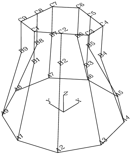
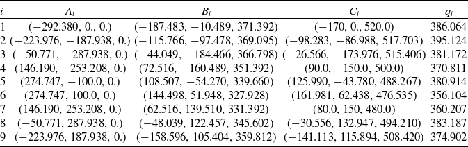
mm. Applying the formulae developed in Subsection 3.1, Table I shows the coordinates of key points of the parallel manipulator as well as the corresponding nine generalized coordinates
 $q_i$
meeting the chosen pose of the configurable platform. Furthermore, for clarity, the unique posture of the robot is depicted in a wire frame model made in Autocad in Fig. 6.
Wire frame model in Autocad of the parallel manipulator meeting the chosen pose of the configurable platform.

Inverse position analysis.

Let us suppose that starting from the reference configuration sketched in Fig. 6, the grasping points must reach the points
 $C_1=(\!-\!200,10.0,700.0)$
mm,
 $C_4=(70.0,-100.0,750.0)$
, and
 $C_7=(120.0,120,720.0)$
mm. The motion of the generalized coordinates must be adjusted in such a way that the robot starts from rest and after 5 seconds reaches the desired position returning again to rest, both in velocity and acceleration. It is desired to determine the generalized coordinates
 $q_i(i=1,2,3,\ldots,9)$
as functions of time
 $t$
satisfying such conditions.
In the final pose of the robot, one obtains that
 $q_1=563.941$
mm,
 $q_2=595.428$
mm,
 $q_3=609.445$
mm,
 $q_4=619.443$
mm,
 $q_5= 611.522$
mm,
 $q_6=598.307$
mm,
 $q_7=594.210$
mm,
 $q_8=607.433$
, and
 $q_9=587.073$
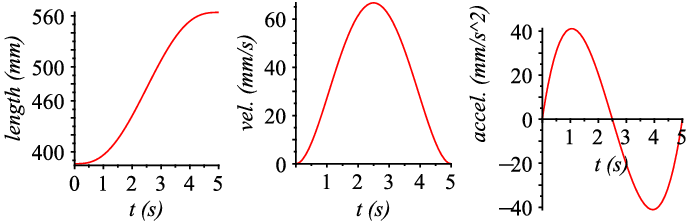
mm. According to Craig [Reference Craig20], fifth-order polynomial equations are a viable option to achieve the assigned task to the grasping points. Hence, by resorting to the inverse position analysis and Craig’s method, the generalized coordinates result in
 \begin{align*} q_1&= 386.064+14.23016000t^3-4.269048000t^4+.3415238400t^5 \\[5pt] q_2&= 395.125+16.02424000t^3-4.807272000t^4+.3845817600t^5 \\[5pt] q_3&= 381.172+18.26168000t^3-5.478504000t^4+.4382803200t^5 \\[5pt] q_4&= 370.811+19.89056000t^3-5.967168000t^4+.4773734400t^5 \\[5pt] q_5&= 380.914+18.44864000t^3-5.534592000t^4+.4427673600t^5 \\[5pt] q_6&= 356.104+19.37624000t^3-5.812872000t^4+.4650297600t^5 \\[5pt] q_7&= 360.207+18.72024000t^3-5.616072000t^4+.4492857600t^5 \\[5pt] q_8&= 383.187+17.93968000t^3-5.381904000t^4+.4305523200t^5 \\[5pt] q_9&= 374.902+16.97368000t^3-5.092104000t^4+.4073683200t^5 \end{align*}
For clarity, Fig. 7 shows the temporal behavior of the generalized coordinate
 $q_1$
.
Time history of the generalized coordinate
 $q_1$
.

Forward position analysis
Let us consider that the generalized coordinates
 $q_i(i=1,2,3,\ldots,9)$
are given by the values obtained in the inverse position analysis that are listed in Table I. That is, the generalized coordinates are given by
 $q_1=386.064$
mm,
 $q_2=395.124$
mm,
 $q_3=381.172$
mm,
 $q_4=370.811$
mm,
 $q_5=380.914$
mm,
 $q_6=356.104$
mm,
 $q_7=360.207$
mm,
 $q_8=383.187$
mm, and
 $q_9=374.902$
mm. Once the higher nonlinear system of eighteen equations
 $f_i$
are generated, it is solved by means of the Newton-homotopy method. To this end, the new equations are formulated as
 \begin{align} h_i=tf_i+(1-p) g_i \quad i=1,2,\ldots,18 \end{align}
where the parameter
 $p$
must be given in the interval
 $0\lt p\lt 1$
. Meanwhile, the auxiliary functions of homotopy
 $g_i$
are chosen as linear combinations of the unknowns
 $w_i(i=1,2,3,\ldots,18)$
. Trying different values for
 $p$
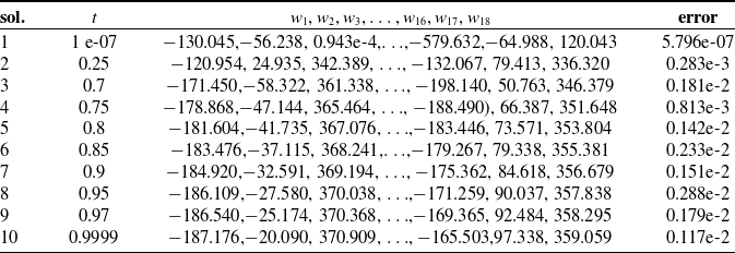
with the same initial values for the variables and the same auxiliary functions of homotopy, ten solutions of the forward position analysis are listed in Table II.
Solution 10 of Table II is precisely the solution of the inverse position analysis listed in Table I where the corresponding posture of the robot is depicted in Fig. 6. For the sake of completeness, the remaining unknowns of solution 10 were obtained as
 \begin{align*} w_4=-34.317,w_5=-185.860,w_6= 366.881,w_7= 80.515,w_8=-154.664,w_9= 351.392, \\[5pt] w_{10}= 139.966,w_{11}= 61.552, w_{12}= 327.362,w_{13}= 53.208,w_{14}= 144.392,w_{15}= 330.549 \end{align*}
Infinitesimal kinematics
Let us consider that the reference configuration of the robot is given according to the data provided in Table I, see Fig. 6. Furthermore, from the reference configuration of the robot, the limbs are conditioned to satisfy length variations given by
 $ \delta q_i=\delta _i \sin\!(t) \cos\!(t+\pi/2)$
mm where
 $\delta _1=60.0$
mm,
 $ \delta _2=55.0$
mm,
 $\delta _3=55.0$
mm,
 $\delta _4=60.0$
mm,
 $\delta _5=70.0$
mm,
 $\delta _6=60.0$
mm,
 $\delta _7=80.0$
mm,
 $\delta _8=60.0$
mm, and
 $\delta _9=65.0$
mm.
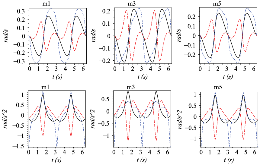
The temporal behavior of the angular velocity and acceleration of the terminal links
 $m_1$
,
 $m_3$
, and
 $m_5$
is provided in Fig. 8.
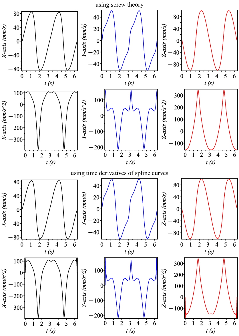
On the other hand, Fig. 9 shows the temporal behavior of the velocity and acceleration of point
 $C_1$
. These plots are compared with plots generated with a different approach that consists of the following steps: 1) adjust to spline curves the temporal behavior of the coordinates of point
 $C_1$
, 2) compute the temporal behavior of the velocity of point
 $C_1$
as the time derivatives of the functions established in step 1, and 3) compute the temporal behavior of the acceleration of point
 $C_1$
as the time derivatives of the functions established in step 2. For example, the spline function associated to the coordinate
 $X$
of point
 $C_1$
was obtained as
Ten solutions applying the Newton-homotopy method.

Time history of the angular velocity and acceleration of the ternary links (
 $\_X$
,
 $---Y$
,
 $-\cdot -\cdot -Z$
).

 \begin{align*} X(t)&=-169.9999992+1.48735000299999998t+398.224316699999974t^3, \\[5pt] &t \lt 0.5235987758e-1 \\[5pt] X(t)&=-170.1143275+4.76261373100000008t+62.5529294188796642(t-0.5235987758e-1)^2 \\[5pt] &-101.484673500000000(t-0.5235987758e-1)^3, \quad t \lt .1047197551 \\[5pt] X(t)&=-171.2374786+15.6645157800000004t+52.4345541590447937(t-.1570796327)^2 \\[5pt] &+1.51353256800000002(t-.1570796327)^3, \quad t \lt .1570796327 \\[5pt] X(t)&=-104.7174901-10.4785195699999996t+46.6110707681354556(t-6.178465554)^2+\\[5pt] &101.498698899999994(t-6.178465554)^3, \quad t \lt 6.230825429 \\ \vdots \end{align*}
 \begin{align*} X(t)&=-140.1898644-4.76262663300000000t+62.5544483276969602(t-6.230825429)^2\\[5pt] &-\!398.233975699999974(t-6.230825429)^3, \quad \text{otherwise} \end{align*}
Time history of the velocity and acceleration of the grasping point
 $C_1$
.

7. Conclusions
In this work, the infinitesimal kinematics of a parallel manipulator provided with a 6-R configurable platform is approached by means of the theory of screws. The input–output equations of velocity and acceleration of the 9-UPU{6R} robot manipulator are systematically obtained by choosing a link of the configurable platform as if it was the rigid platform of a conventional parallel manipulator. The systematic application of reciprocal screw theory allows to cancel the passive joint rate velocities and accelerations of the robot simplifying the velocity and acceleration analyses of the robot. As an intermediate step, the displacement analysis of the proposed robot is approached by means of simple concepts of vectorial algebra. The inverse displacement analysis leads to a closed-form solution which yields a unique solution. On the other hand, the direct position analysis of the robot is more complex due to the large number of nonlinear equations generated from the closure equations. Then, the Newton-homotopy method is employed to find some solutions of the forward displacement analysis. The contribution is accompanied by numerical examples that illustrate the reliability of the method of kinematic analysis employed. The mobility of the robot allows to control the position of three end-effectors mounted on different links of the configurable platform which can be employed for instance to execute tasks like grasping objects and pick-and-place operations with multiple end-effectors.
Conflicts of interest
None.
Financial support
None.
Ethical considerations
None.
Authors’ contributions
Jaime Gallardo-Alvarado conceived the topology of the manipulator and performed the displacement analysis of it. Mario A. Garcia-Murillo conducted the infinitesimal kinematics of the robot. Ramon Rodriguez-Castro developed the algorithm for the numerical computation of the kinematic analysis of the robot.