


I. INTRODUCTION
The employment of wireless radio frequency identification (RFID) and wireless sensor systems has grown extensively in the past decade. Nowadays, RFID systems are found in logistics, medical environments, or even supermarkets. Wireless sensors are becoming irreplaceable elements in industrial environments and aid in numerous controls and monitoring tasks.
Motivated by this development, a particular interest arises in the development of chipless wireless RFID and sensing systems. These systems operate in the lower gigahertz range and their tags work entirely in the electromagnetic domain. The wireless tags do not use any semiconductor-based integrated circuits and do not require a local power supply. Hence, they offer application potential in excess of chip-based systems: they can enable operation in the very low-cost regime [Reference Preradovic and Karmakar1] or in harsh environments, e.g. at very high temperatures.
With a strong similarity to some chipless radio frequency (RF) identification tags [Reference Schüßler, Maasch, Damm and Jakoby2–Reference Vena, Perret and Tedjini4], a promising approach to realize chipless sensor tags is the use of RF backscatter signals with spectral signatures to encode and transmit the measurement value. This principle has been used to realize chipless temperature [Reference Cheng, Ebadi and Gong5–Reference Kubina, Mandel, Schüßler, Sazegar and Jakoby7], strain [Reference Mandel, Schüßler and Jakoby8–Reference Thai, Aubert, Pons, Plana, Tentzeris and DeJean10], displacement [Reference Mandel, Kubina, Schüßler and Jakoby11], and gas [Reference Yang, Orecchini, Shaker, Lee and Tentzeris12] sensors.
However, one key aspect occurring during the employment of fully chipless RF sensors has been treated very little in the literature, which is the challenge to readout the sensors in time-variant environments. Some static reading scenarios have been presented that face reflections from standing objects with reference measurements [Reference Preradovic and Karmakar3, Reference Vena, Perret and Tedjini4, Reference Mandel, Schüßler and Jakoby8, Reference Melik9], or time-gating [Reference Cheng, Ebadi and Gong5, Reference Kubina, Mandel, Schüßler, Sazegar and Jakoby7, Reference Mandel, Kubina, Schüßler and Jakoby11]. But the impact of moving objects in the vicinity of the reader or the tag has hardly been studied or counteracted [Reference Kubina, Mandel, Schüßler and Jakoby13].
This work presents a channel estimation (CE) method to estimate and suppress the interference caused by a dynamic object in a wireless reading scenario. The interfering signal is characterized in two frequency bands adjacent to the tag's transmission band. Together with an optimization routine, the characterization yields an estimate of the interfering signal and a corrected measurement signal. The proposed method has been successfully tested in two wireless proof-of-concept scenarios with a chipless strain sensor and a chipless temperature sensor. A metallic block acted as a dynamic interferer.
II. OUT-OF-BAND CE METHOD
In a chipless wireless sensor-reading scenario, as drawn in Fig. 1, a reader, the sensor tag, and a number of ambient objects are part of the measurement space. The received signal is a sum of backscatter signals, including interference signals from the objects plus the useful tag response.
Wireless sensor scenario: the sensor tag is located close to a static and a dynamic interferer.

For the proposed method, reflections from static objects and the reader antenna mismatch are suppressed by reference measurements. Assuming that an approximate distance between reader and tag antenna is known, time-gating methods filter out background reflections, i.e. reflections from the static or dynamic objects far away from reader and tag. This way, one reduces the number of relevant dynamic interferers to a minimum. In this paper, as a first approach, one single dynamic interfering object is taken into consideration. A metal block is used as a representative for various moving metallic objects that might be found in an application environment, e.g. a robot arm or a die cutter on a manufacturing site. The block is placed in different positions to imitate a dynamic movement of the interferer.
To analyze this reading scenario the following subsections show a few theoretical considerations as well as a description of the measured signal and its processing to gain an estimate of the dynamic channel impulse response and of the desired tag signal.
A) Theoretical analysis
In a backscatter scenario, the power that is received from an arbitrary object with radar cross section (RCS) is given by the radar equation [Reference Pozar14]. According to this, the normalized Rx power from an interfering object in the measurement room is proportional to its cross-section RCSI. The interferer's normalized Rx signal S I at the reader can be derived from the radar equation. As a function of the frequency f, it is given by
 $$S_I \lpar\, f\rpar =\sqrt {{\rm RCS_I} \lpar\, f\rpar } \displaystyle{{A_R f} \over {\sqrt {4\pi } c_0 r^2 }}e^{j\varphi _I \lpar\, f\rpar }\comma \;$$
with the Rx phase φI, the reader-to-object distance r and the speed of light c 0, if an aperture antenna at the reader side with aperture size A R is assumed.
Setting a metallic block as the interfering object, the block's Rx signal becomes
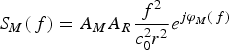 $$S_M \lpar\, f\rpar =A_M A_R \displaystyle{{f^2 } \over {c_0^2 r^2 }}e^{j\varphi _M \lpar\, f\rpar }$$
with phase φM, if the RCS of the block is approximated with RCSM = A M24πf 2/c 02 and its cross-sectional area is A M. The signal amplitude of the block backscatter shows a quadratic decrease with increasing distance r and a quadratic increase with increasing frequency f.
According to (1), the desired signal S T of the sensor tag with RCST is
 $$S_T \lpar\, f\rpar =\sqrt {{\rm RCS}_T \lpar\, f\rpar } \displaystyle{{A_R f} \over {\sqrt {4{\rm \pi }} c_0 r^2 }}e^{j\varphi _T \lpar\, f\rpar }$$
with its Rx phase φT(f).
The considered group of chipless sensors use the tag's RCS to encode the desired information. The measured value is calculated from a resonance peak in the tag's cross-section RCST. Hence, this approach is called frequency position encoding [Reference Mandel, Kubina, Schüßler and Jakoby15].
In the measurement scenario, the useful tag signal S T adds up with the interfering signal including both amplitudes and phases. The decoding of the measured value from the tag's resonance peak is then strongly affected by this complex sum. The peak can (a) remain a maximum if tag signal and interference signal are in phase, (b) become a minimum for 180° phase shift between the phases of the received signals, i.e. φT − φI = π or (c) have any amplitude value in between for arbitrary phase constellations. Consequently, one sees the peak position shifting or vanishing in dependence of the local tag and interferer constitution and hence, the measurement decoding becomes erroneous or even impossible.
B) Received signals in practice
Describing the received signal after the above-mentioned reference and time-gating methods, the measured received signal  $\overline S $ is taken as the sum of the measured tag signal
 $\mathop {\overline S }\nolimits_T \lpar\, f\rpar $ and the measured backscatter
 $\mathop {\overline S }\nolimits_I \lpar\, f\rpar $ from the dynamic interferer
 $$\overline S \lpar\, f\rpar =\mathop {\overline S }\nolimits_T \lpar\, f\rpar +\mathop {\overline S }\nolimits_I \lpar\, f\rpar.$$
These tag and interference signals,  $\mathop {\overline S }\nolimits_T \lpar\, f\rpar $ and
 $\mathop {\overline S }\nolimits_I \lpar\, f\rpar $, can be approximated by the theoretical expressions S T(f) and S I(f) in (3) and (1).
The CE method splits up the received signal  $\overline S \lpar\, f\rpar $ into three bands: The tag backscatter band B 0 as the set of frequencies between f 0,1 and f 0,2, the lower estimation band B 1 = [f 1,1, f 1,2] and the upper estimation band B 2 = [f 2,1, f 2,2] as shown in Fig. 2. The tag backscatter band B 0 is the range in which the tag's resonance is expected, and carries both the useful signal and the interfering signal
 $$\mathop {\overline S }\nolimits_{B\comma 0} \lpar\, f\rpar =\mathop {\overline S }\nolimits_T \lpar\, f\rpar +\mathop {\overline S }\nolimits_I \lpar\, f\rpar \, \, {\rm for}\, f \in B_0.$$
Principle of the channel estimation method. The tag signal shows a resonance peak, who is tuned by the measurement value. This tag signal is disturbed by the interference signal. The interference signal is characterized in the two estimation bands adjacent to the tag backscatter band.
The presented method assumes that in the two estimation bands the RCS of the tag is negligibly small, so that the measured bands' Rx signals  $\mathop {\overline S }\nolimits_{B\comma 1} $ and
 $\mathop {\overline S }\nolimits_{B\comma 2} $ are approximately
 $$\mathop {\overline S }\nolimits_{B\comma 1} \lpar\, f\rpar \approx \mathop {\overline S }\nolimits_I \lpar\, f\rpar \comma \; \; {\rm for}\; f \in B_1\comma \;$$
and
 $$\mathop {\overline S }\nolimits_{B\comma 2} \lpar\, f\rpar \approx \mathop {\overline S }\nolimits_I \lpar\, f\rpar \comma \; \; {\rm for}\; f \in B_2.$$
Consequently, the two estimation bands allow a view onto the spectral characteristic of the dynamic interferer in a limited frequency range. This separation of the interference signal is a key element of the presented approach. The estimation bands are used to find spectral properties of the interference signal. The spectrum of the interference signal in the central tag backscatter band is afterwards estimated from these properties.
C) Estimation signals
Based on the measured estimation band signals  $\mathop {\overline S }\nolimits_{B\comma 1} $ and
 $\mathop {\overline S }\nolimits_{B\comma 2} $, the CE method aims at finding an estimate
 $\mathop {\hat S}\nolimits_I $ of the interference signal
 $\mathop {\overline S }\nolimits_I $ for the central tag backscatter frequency range. This estimate is complex in order to include both magnitude and phase of the interference.
Using the approximations of (6) and (7), the estimation signal  $\mathop {\hat S}\nolimits_I $ is settled to approximate amplitude and phase of the lower and upper estimation band signals. So, the two estimation band errors ϵ1 and ϵ2
 $${\rm \epsilon }_1=\vint_{f_{1\comma 1} }^{f_{1\comma 2} } \, \left\vert {\mathop {\overline S }\nolimits_{B\comma 1} \lpar\, f\rpar - \mathop {\hat S}\nolimits_I \lpar\, f\rpar } \right\vert \; df\comma \;$$
 $${\rm \epsilon }_2=\vint_{f_{2\comma 1} }^{f_{2\comma 2} } \, \left\vert {\mathop {\overline S }\nolimits_{B\comma 2} \lpar\, f\rpar - \mathop {\hat S}\nolimits_I \lpar\, f\rpar } \right\vert \; df$$
are defined to describe the magnitude of the complex difference between estimate and measured signal in the two estimation bands. The sum error ϵt of these two errors
 $${\rm \epsilon }_t={\rm \epsilon }_1+{\rm \epsilon }_2 \to 0$$
is then taken as an optimization/minimization criterion to find a suitable interference signal estimate.
The estimate  $\mathop {\hat S}\nolimits_I $ of the unknown interference signal
 $\mathop {\overline S }\nolimits_I $, is set up as a number of N weighted Dirac pulses
 $$\mathop {\hat s}\nolimits_I \lpar t\rpar =\sum\limits_{i=1}^N \left({A_i \, e^{j\varphi _i } \delta \lpar t - \tau _i \rpar \ast g_i \lpar t\rpar } \right)\comma \;$$
which are represented in frequency domain by a sum of complex oscillations
 $$\mathop {\hat S}\nolimits_I \lpar\, f\rpar =\sum\limits_{i=1}^N A_i e^{j\lpar 2\pi f\tau _i - \varphi _i \rpar } G_i \lpar\, f\rpar$$
with the Fourier-transformed weighting function G i(f) = ℱ(g i(t)). As indicated in (2), the RCS of many metallic objects shows a frequency dependent amplitude increase. This behavior is imitated by the weighting function G i(f)
 $$G_i \lpar\, f\rpar =\lpar\, f - f_0 \rpar \alpha _i+1$$
with the linear slope α i and the reference frequency f 0.
This CE approach leads to four unknowns for the ith Dirac pulse: magnitude A i, phase φi, instant of time τ i, and slope α i. For a set of N pulses the total number of unknowns becomes then 4N. These unknowns have to be found with a suitable optimization method to satisfy the criterion of (10). In this work, a sequential optimization algorithm is used, which is described in the following Section D).
After the optimization, the desired tag signal S T is estimated as  $\mathop {\hat S}\nolimits_T $ by subtracting the interference signal estimate
 $\mathop {\hat S}\nolimits_I $ from the measured Rx signal
 $$\mathop {\hat S}\nolimits_T \lpar\, f\rpar =\overline S \lpar\, f\rpar - \mathop {\hat S}\nolimits_I \lpar\, f\rpar.$$
The tag's resonance peak at f r, from which the measured value is concluded in a sensor application, is estimated as the frequency  $\mathop {\hat f}\nolimits_r $, which shows the largest magnitude in
 $\mathop {\hat S}\nolimits_T \lpar\, f\rpar $ within the backscatter band B 0. The difference
 $$\eqalignno{{\rm \epsilon }_{f_r }& =f_r - \mathop {\hat f}\nolimits_r \cr& =f\lpar {\rm max}\; \vert \mathop {\overline S }\nolimits_T \lpar\, f\rpar \vert \rpar - f\lpar {\rm max}\; \vert \mathop {\hat S}\nolimits_T \lpar\, f\rpar \vert \rpar \; \; {\rm for}\,f\, \in B_0 &}$$
between the true and estimated resonance frequency as well as the phase estimation error
 $${\rm \epsilon }_\varphi=\overline \varphi - \hat \varphi=\angle \overline S \lpar\, f\rpar - \angle \mathop {\hat S}\nolimits_I \lpar\, f\rpar$$
are taken as measures for the quality of the interference estimation and shown in Section IV for a practical scenario.
D) Sequential optimizer
As described above, the presented CE method assumes a number of N-weighted Dirac pulses to estimate and suppress the unwanted interference signal. In order to find an optimal estimate, 4N unknowns have to be found as (12) indicates: the magnitude A i, phase φi, time instant τ i, and slope α i of each of the N pulses.
To find the set of variables a sequential optimizer is used, which runs N-sequence steps, and determines magnitude, phase, time instant, and slope of the ith pulse of (11) in one sequence step. This sequential approach is mainly taken to minimize the computational complexity of the optimization problem by avoiding the necessity to optimize a joint 4N-dimensional criterion.
In the ith sequential step, an initial estimate of the four unknowns is found by using the discrete Fourier transform (DFT) of the estimation bands' received signals  $\mathop {\overline S }\nolimits_{B\comma 1} $ and
 $\mathop {\overline S }\nolimits_{B\comma 2} $. This initial estimate is optimized with the criterion in (10) using (12) with N = 1. This optimization leads to an intermediate estimation signal. The intermediate estimation signal is subtracted from the measured signal and the sequence is restarted for (i + 1). The final estimate
 $\mathop {\hat S}\nolimits_P $ is summed up as given in (12) with the set of all optimized variables from all optimization sequences.
III. THE SENSOR TAGS
The presented CE method has been tested with two different chipless sensor tags. This section describes the setup and functionality of the two tags.
The first tag is a strain sensor and has been presented in [Reference Mandel, Schüßler and Jakoby8]. The strain sensor is built up as a composite right-/left-handed microstrip mushroom structure. The gap between the two mushroom elements forms a capacity, which is varied by the gap width (see Fig. 3(a)). Together with the line and via inductance a shorted resonant antenna structure is formed. The antenna's resonance can be measured wirelessly as a peak in the RCS. The peak shifts between 3.05 and 3.2 GHz for gap widths between 250 and 600 µm. This behavior can be used to measure corresponding mechanical strains of up to 140%. A photo of the 1.5 × 1.5 cm2 large tag is shown in Fig. 3(b).
Photographs of the strain (b) and temperature (d) sensors as well as functionality principles of the sensor tags. (a) The resonant frequency of the strain sensor is detuned by the capacity between the mushroom elements. (c) The TE011+δ mode used in the temperature sensor.
The second tag is a temperature sensor that has been presented in [Reference Kubina, Schüßler, Mandel and Jakoby16]. The sensor is built from a half-split cylindrical dielectric resonator (DR) placed on a metallic ground plane. An incident RF wave excites the TE011+δ-mode (see Fig. 3(c)) inside the DR, which is seen as a resonance peak in the RCS. The resonance frequency f r and hence, the peak position, shift temperature-dependent due to the dependency of the DR's permittivity on the temperature ϑ. The sensor's resonance lies at 2.91 GHz at room temperature and shows a sensitivity of Δf r/Δϑ = 307 kHz/K. The resonator has a diameter of 2 cm and height of 1.5 cm, whereas the aluminum ground sheet has a size of 9 cm × 9 cm. A photograph of the tag is shown in Fig. 3(d).
The two tags use very similar principles for the chipless sensing, which is mainly the usage of resonant structures and a detuning of their resonance frequency. They both use frequency-position encoding [Reference Mandel, Kubina, Schüßler and Jakoby15] of the measurement value. While the resonance frequencies of both tags lie about 3 GHz, one main difference between them are their resonance bandwidths. While the strain sensor shows resonance quality factors about 50, the temperature sensor's quality factor is about a factor 11 times higher at 550. The impact of this difference on the performance of the CE method is described in the following Section IV.
IV. MEASUREMENTS
In order to prove the presented interference suppression method and to evaluate its performance, wireless measurements have been performed. During these measurements, a chipless wireless strain sensor tag and a temperature sensor tag have been used. The setup and functionalities of these two tags have been presented in the previous Section III. During the measurements a metallic block acts as an interfering object. The block is placed at different positions to imitate a dynamic movement of the interferer. This imitation assumes a movement of the interferer, which is slow compared to a measurement cycle. Furthermore, the imitation assumes that Doppler shifts due to the movement can be neglected. This negligence appears reasonable, since an object velocity of up to 100 km/h would cause shifts of less than 280 Hz at the operation frequency. This shift would be very small compared to the estimation error margin, which is in the MHz range as presented below.
A) Measurement setup
The measurements have been conducted in a hall where a vector network analyzer, connected to a horn antenna, has been used as a reader. The two sensor tags have been placed in two similar setups on a stand in front of the horn antenna. The setups are shown in Fig. 4(a) for the strain sensor and in 4(b) for the temperature sensor. In both cases, a metallic block has acted as the dynamic interfering object. For the temperature sensor setup, a heat gun and an infra-red camera have been used to control the temperature of the tag.
Photographs of the two measurement setups.
In the strain sensor setup, the distance d 1 between the tag and horn antenna has been 60 cm. The metal block, which acts as a dynamic interferer, has a cross-section of 4.5 × 9 cm2 (18 times the area of the tag). It has been placed in a distance d 2 = 10 cm next to the tag as shown in Fig. 5.
Top view of the placement of reader antenna, sensor tag, and metal block during the measurements. The block has been placed at five different positions to imitate a dynamic movement of the interferer.
For the temperature sensor tag, the distance d 1 between tag and horn antenna has been 85 cm. A metal block with a cross-sectional area of 10 × 12 cm2 (40 times the area of the DR) has been chosen and placed at d 2 = 10 cm next to the tag. In comparison to the strain sensor, the temperature tag shows a higher received power for identical reading distances. Owing to this reason a larger distance d 2 has been chosen to have similar peak powers in both setups. A larger metal block was chosen, to keep the ratio between tag and interference power, i.e. the signal-to-inference ratio (SIR) comparable.
In both setups, the metal block has been placed at five different positions in order to imitate a dynamic movement of the interferer. The five different positions are named P 0 to P 4 and are spaced by d 3 = 1 cm as shown in Fig. 5. This positioning includes a shift of the interferer's phase φI by 360° at the center-operating frequency of 3 GHz in order to comprise constructive, destructive and intermediate superposition of tag and interference signal. These five block positions have been combined with two different measurement values/resonance frequencies of each tag, so that ten combinations of block position and measurement value are evaluated for each setup.
The measurement values of the strain setup are the gap widths W 1 = 345 µm and W 2 = 535 µm with resonant frequencies 3.100 and 3.176 GHz. For the temperature tag, ambient temperatures of 20 and 35°C have been set with resonant frequencies at 2.914 GHz and 5.75 MHz higher at 2.920 GHz.
The resonance shift in absolute terms of the temperature tag is about a factor 13 times smaller than for the strain tag. This setting has been chosen intentionally, in order to attain comparable results. As mentioned in Section III, the temperature sensor shows an 11 times higher resonance Q-factor than the strain tag and has an 11 times smaller bandwidth. Hence, the resonance shift of the two setups is nearly identical in relation to the peak bandwidth.
According to the CE approach described in Section II, the subsequently presented measured signals are obtained under assistance of a differential measurement of the ‘empty’ hall, i.e. without tag and metal block, to minimize the impact of static interferers. Furthermore, time gating has been applied to filter out background interferers.
B) Results
Figure 6 shows the measured signal of the two sensor tags and of the metal blocks separately. For the strain sensor, the resonant peaks at 3.100 and 3.178 GHz are identified in Fig. 6(a). The metal block alone shows a rippled response signal with quadratically increasing amplitude. A comparison between the block response at the two positions P 1 and P 2 shows comparable amplitude but different phase. The ratio between tag peak power and average block interference power is SIR = 0.52.
Measurements of the sensor tags and of the metal block ‘alone' in the setup. (a) Strain tag with gap widths W 1 and W 2 and metal block at positions P 1 and P 2. (b) Temperature tag at temperatures θ1 and θ2, and the metal block at positions P 3 and P 4.
The resonance peaks of the temperature sensor are seen in Fig. 6(b) with amplitudes of about 6.4 × 10⁻³. The backscatter signals of the metallic block are slightly stronger and show stronger ripples than in the strain sensor setup. The SIR in the second setup is 0.3.
Examples of the performance of the CE methods are shown in Fig. 7. When both, tag and block are placed in front of the reader antenna, the received signal does not show the tag peaks any more. A detection of the resonant peak of the tag is not possible in these disturbed Rx cases. The strong distortions are visible in both cases for the strain sensor with block position P 2 and gap width W 1 (see Fig. 7(a)) as well as for the temperature sensor tag with block position P 4 and temperature ϑ0 (see Fig. 7(b)).
Exemplary results of the presented CE method: measured (Meas.), estimated (Est.), and corrected (Corr.) signals and the tag-only (Tag) measurement. The two estimation bands are marked grey shaded. (a) For the strain tag with gap W 1 = 345 µm and block position P 2, (b) for the temperature tag with θ1 = 20° C and block position P 4.
With the presented CE algorithm, estimates of the interference signals are obtained and the difference between Rx signal and interference estimation signals are shown, which yield the tag signal estimates. The tag signal estimates show good reconstructions of the tags' transmission characteristics. Some amplitude differences are visible between the true and estimated peak, which are partly caused by the influence of the metal block onto the radiation pattern of the tags. The decisive peak positions are found with very slight offsets. For the strain sensor example, the difference between the true and estimated peak frequency ϵf r (compare (15)) is equal to 2 MHz. For this example, a number of N = 2 Dirac pulses was taken to approximate the interference signal with the estimation bands B 1 = [2.5, 2.8 GHz] and B 2 = [3.3, 3.6 GHz].
For the temperature sensor, the estimation error in the example is ϵf r = −0.25 MHz. N = 1 Dirac pulse was taken as an approximation with the bands B 1 = [2.86, 2.89 GHz] and B 2 = [2.94, 2.97 GHz].
In both setups, the number of Dirac pulses has been chosen as small as possible (to keep the computational effort low) while achieving smallest estimation errors. Higher pulse numbers N did not lead to significantly better results.
Figure 8 shows the phase estimation error ϵφ of (16) and the absolute phase of the metal block. Within the estimation bands B 1 and B 2 the phase error lies between ±20° and shows largest slope at the estimated resonance positions. A comparison between Figs 8(a) and 8(b) shows the significantly smaller absolute phase steepness of the interference signal, due to the ten times smaller bandwidth of the temperature sensor setup.
With the above-mentioned estimator settings all ten combinations between the two tag resonance positions and the five block positions have been evaluated, leading to the results listed in Fig. 9. For the strain tag, the resonance peak of the tag has been found under support of the CE method with maximum deviations ϵf r of −12 to 6 MHz. In comparison, if no CE algorithm is applied, the backscatter band maxima are spread with a maximum error between −102 and 90 MHz.
Resonance position error from (15) for the different tag to block constellations, given in absolute terms and relative to the sensors' frequency ranges.
For the temperature tag, the resonance estimation error ϵf r is found within an interval of −0.75 and 0.25 MHz. This result is seen in comparison to peak deviations between −15.50 and 8.00 MHz without the CE method.
C) Result discussion
The results of the measurements show a significant error reduction achieved by the proposed CE method. The impact of the dynamic interferer is strongly reduced.
For the strain sensor tag, an average estimation error of 3.8 MHz is observed, which is equivalent to a relative error of 1.9% in relation to a 200 MHz measurement range. For the temperature sensor, the average estimation error is 0.35 MHz, equivalent to 1.75% relative to a 20-MHz measurement range.
Despite a smaller SIR of the temperature tag measurements, a ten times smaller estimation error in absolute terms is seen compared to the strain sensor setup. A strong correlation with the about ten times higher resonance Q of the temperature sensor is observed. Consequently, one concludes that the estimation error scales with the RCS peak bandwidth of the tag. A higher resonance Q leads to a more robust detection.
Furthermore, it should be noted, that the temperature control during the temperature tag setup has been limited in accuracy. From the observations an absolute control inaccuracy of ±0.4°C has to be assumed, which correlates to a resonance offset of ±0.12 MHZ. Consequently, the average estimation error of 0.35 MHz of the setup is only about three times larger than the temperature uncertainty.
The given estimation results have been achieved with calculations on a standard office computer. Each estimation procedure took about 0.6 s computation time, which consequently allows for real-time applications with update rates in the lower Hertz range. However, a couple of computational speed optimizations are thinkable to improve the estimation speed.
V. CONCLUSION AND OUTLOOK
A channel estimation method for chipless wireless sensor tags has been presented. This method estimates a dynamic interfering signal and corrects the disturbed received signal to regain the spectral signature of the tag.
The method uses two adjacent bands in which the useful tag signal tends to zero to find an estimation signal, which is constructed as a sum of weighted Dirac pulses. A sequential optimizer is used within the method to calculate the estimate on the basis of a DFT signal analysis.
The method has been applied in two indoor reading scenarios with a chipless strain sensor and a chipless temperature sensor. In these scenarios, the interfering signal originated from a metal block placed in different positions to imitate a dynamic movement of an interfering object. Here, the method has proven to be able to successfully suppress the dynamic interferer and to enable a reconstruction of the spectral tag signatures.
During the strain sensor setup with an SIR of 0.52, the reconstruction showed a resonance peak deviation error below 12 MHz and an average deviation of 3.8 MHz equivalent to about 1.9% of the operating frequency range and compared to a deviation of up to 102 MHz without the CE method.
The temperature sensor setup showed a more robust detection, due to its smaller peak bandwidth. With an SIR of 0.30, a reconstruction with an error below 0.75 MHz with an average value of 0.35 MHz has been achieved. This average error relates to about 1.75% of the operating frequency range. Without application of the CE method peak deviations of up to 15.5 MHz have been observed.
The method is seen as one step to bring chipless sensors into dynamic application environments. A general scaling of the estimation error with the peak and estimation bandwidth has been concluded.
Further developments of the method will include a refinement of the optimizer. Furthermore, an application of the method with cross-polarized tags and with chipless RFID tags is planned.
ACKNOWLEDGEMENTS
The authors would like to thank Mr. Andreas Semrad and Mr. Peter Kiesslich for their technical support as well as the German Research Foundation DFG for the support within project JA921/38-1.
Bernd Kubina received the diploma degree in Electrical Engineering from the Technische Universität (TU) Darmstadt, Germany, in 2010. Since 2011 he is with the Institute for Microwave Engineering and Photonics at the TU Darmstadt as a Research Associate. His research interests include wireless sensors, RFID systems, and ferroelectric materials.
Christian Mandel received the Diploma degree in Electrical Engineering and Information Technology from the Technische Universität Darmstadt in Germany in 2009. He is currently with the Institute for Microwave Engineering and Photonics at the TU Darmstadt and working toward the Ph.D. His research interests include chipless RFID and chipless wireless sensors.
Martin Schüßler received the Dipl.-Ing. and Ph.D. degrees from the Technische Universität Darmstadt, Germany, in 1992 and 1998, respectively. Since then he is a staff member of the Institute for Microwave engineering and Photonics of the Technische Universität Darmstadt. During his career he worked in the fields of III–V semiconductor technology, microwave sensors for industrial applications, RFID, and small antennas. His current research interests include the application of metamaterials for industrial and biomedical sensing.
Rolf Jakoby received the Dipl.-Ing. and Dr.-Ing. degrees in Electrical Engineering from the University of Siegen, Germany, in 1985 and 1990, respectively. In January, 1991, he joined the Research Center of Deutsche Telekom in Darmstadt, Germany. Since April 1997 he has a full professorship at TU Darmstadt, Germany. His interdisciplinary research is focused on RFID, micro- and millimeter wave detectors and sensors for various applications, and in particular on reconfigurable RF passive devices, based on liquid crystal and ferroelectric technologies. Rolf Jakoby is Editor-in-Chief of “FREQUENZ”, a member of the Society for Information Technology (ITG) of the VDE and a member of the IEEE societies MTT and AP. He is the organizer of various workshops, member of various TPCs, and has been chairman of the European Microwave Conference 2007 and the German Microwave Conference 2011. In 1997, he received the ITG-Prize for an excellent publication in the IEEE AP Transactions.



