1 Introduction
Heating by Joule dissipation is employed in various industrial processes and particularly in the glass industry. Electric melting is commonly used for production of potentially volatile, polluting glasses, high-added-value products and also in other sectors like wool insulation (Ross & Tincher Reference Ross and Tincher2004). One of the main advantages of this process is its high thermal efficiency due to the bulk heat source and its high level of insulation. Indeed, the introduction of electrodes in the liquid creates electric currents, leading to a volumetric heat source through the Joule effect. Moreover, raw materials overlie the top surface of the furnace, leading to thermal insulation (Stanek Reference Stanek1977). Due to the expansion coefficient of molten glass, natural convection contributes to the chemical and thermal homogenization of the liquid. The level of the convection depends on the glass properties and is one of the main issues for engineers involved in the furnace design.
Molten glass, or more accurately ‘glass former’ liquid, can be considered as a Newtonian fluid and is characterized by a high viscosity. Indeed, when the temperature is approximately
 $1400~^{\circ }\text{C}$
, the dynamic viscosity is approximately ten thousand times greater than that of water (Scholze Reference Scholze1990). Moreover, the thermal conductivity is small even if radiation is the main mode of heat transfer (Viskanta & Anderson Reference Viskanta and Anderson1975). Consequently, one of the main characteristics of molten glass is the high Prandtl number, which can range from
 $10^{2}$
for clear glasses up to
 $10^{5}$
for dark glasses. The Joule-heated problem in the framework of glass synthesis using electrodes has been considered by Curran (Reference Curran1971, Reference Curran1973), who show that the use of uniform electric conductivity does not change the numerical results significantly. He also showed that thermal gradients are more pronounced for dark glass. A three-dimensional numerical simulation has been made by Choudhary (Reference Choudhary1986) in a configuration with horizontal electrodes. In previous work, only stationary solutions are determined and spatial resolution remains poor. Moreover, nothing was done to predict the general features of the scaling laws of velocity and heat transfer. More recently, Sugilal, Wattal & Iyer (Reference Sugilal, Wattal and Iyer2005) studied the flow and heat transfer regimes in a two-dimensional enclosure for a uniform Joule-heated fluid, taking into account the Lorentz force in the momentum balance. They found the critical Rayleigh number numerically and determined the Nusselt number for the stationary regime. Gopalakrishnan et al. (Reference Gopalakrishnan, Thess, Weidmann and Lange2010) performed successful numerical simulations in a two-dimensional configuration to study the mixing of molten glass, dealing with a periodic condition applied to electrodes. They showed that the flow becomes unsteady even with stationary boundary conditions for a dark glass. Nevertheless, the previous contributions have not studied whether instabilities occur from the physics, rather than from poor numerical resolution.
Consequently, the purpose of this work is to study the thermoconvective instabilities which can occur in an enclosure filled with an electrically conducting liquid. Indeed, from the industrial point of view, it is very important to know parameters leading to unsteady behaviour, which can be the source of bad working conditions. In the same spirit as previous works performed to study the heat and mass transfer of liquid non-uniformly heated from above in a rectangular enclosure (Flesselles & Pigeonneau Reference Flesselles and Pigeonneau2004; Pigeonneau & Flesselles Reference Pigeonneau and Flesselles2012; Uguz et al. Reference Uguz, Labrosse, Narayanan and Pigeonneau2014), a simple cavity heated by the Joule effect is considered. The electric field is delivered by two electrodes with lengths corresponding to a fraction of the vertical walls of the enclosure.
Apart from this industrial motivation, natural convection with a volumetric heat source has been studied for a long time. When the source term is spatially uniform, convection appears when the so-called Rayleigh number exceeds a threshold, as in classical Rayleigh–Bénard problems. The critical Rayleigh number depends on the temperature profile determined in a basic solution. One of the first contributions to this topic was made by Tritton & Zarraga (Reference Tritton and Zarraga1967), who experimentally investigated free convection for a uniformly heated layer of water, showing the onset of convection for a smaller Rayleigh number compared to the classical Rayleigh–Bénard problem. The linear stability of the experiment achieved by those authors has been confirmed by Roberts (Reference Roberts1967), who determined the critical Rayleigh number. The thermal behaviour has also been studied when the Rayleigh number is larger than the critical value. Thirlby (Reference Thirlby1970) numerically investigated free convection with an internal heat source for an infinite layer of fluid. Convection was analysed both in two-dimensional and three-dimensional configurations. Kulacki & Goldstein (Reference Kulacki and Goldstein1975) determined the critical Rayleigh numbers both with a linear stability and with an energetic analysis in various cases depending on boundary conditions imposed on the top and bottom walls. Emara & Kulacki (Reference Emara and Kulacki1980) provided a numerical study for a range of Prandtl numbers between 0.05 and 20, and for Rayleigh numbers up to
 $5\times 10^{8}$
.
Despite these contributions, a careful analysis of heat and mass transfer in the case of a non-uniform Joule-heated cavity is still lacking. Even if the occurrence of time-dependent solutions has been seen by Gopalakrishnan et al. (Reference Gopalakrishnan, Thess, Weidmann and Lange2010), the nature of the instability was not characterized accurately. Moreover, unsteady solutions observed by Sugilal et al. (Reference Sugilal, Wattal and Iyer2005) and Gopalakrishnan et al. (Reference Gopalakrishnan, Thess, Weidmann and Lange2010) with poor time and space resolutions are questionable. In this paper, we investigate the case of an enclosure heated in volume with an electric field generated by two electrodes with lengths corresponding to a fraction of the vertical walls. Our main aims are to characterize the flow and the heat transfer as a function of relevant parameters and to analyse the transition regimes in a two-dimensional enclosure. To carry out this work, we develop an accurate numerical solver to study unsteady solutions with a discontinuous Galerkin finite element method.
In the following, § 2 describes the problem statement in which balance equations are presented and assumptions are also specified. In § 3, the numerical accuracy of the solver is assessed in particular for the case where the electrode lengths are equal to the cavity height. In § 4, results obtained for a non-uniform Joule-heated cavity with shortened electrodes are presented. Finally, we draw conclusions in § 5. Appendix A provides a scaling analysis used to normalize the system of equations involved in this problem.
2 Problem statement
We consider a rectangular cavity of length
 $L$
and height
 $H$
filled with an electrically conducting liquid in a gravity field
 $\boldsymbol{g}$
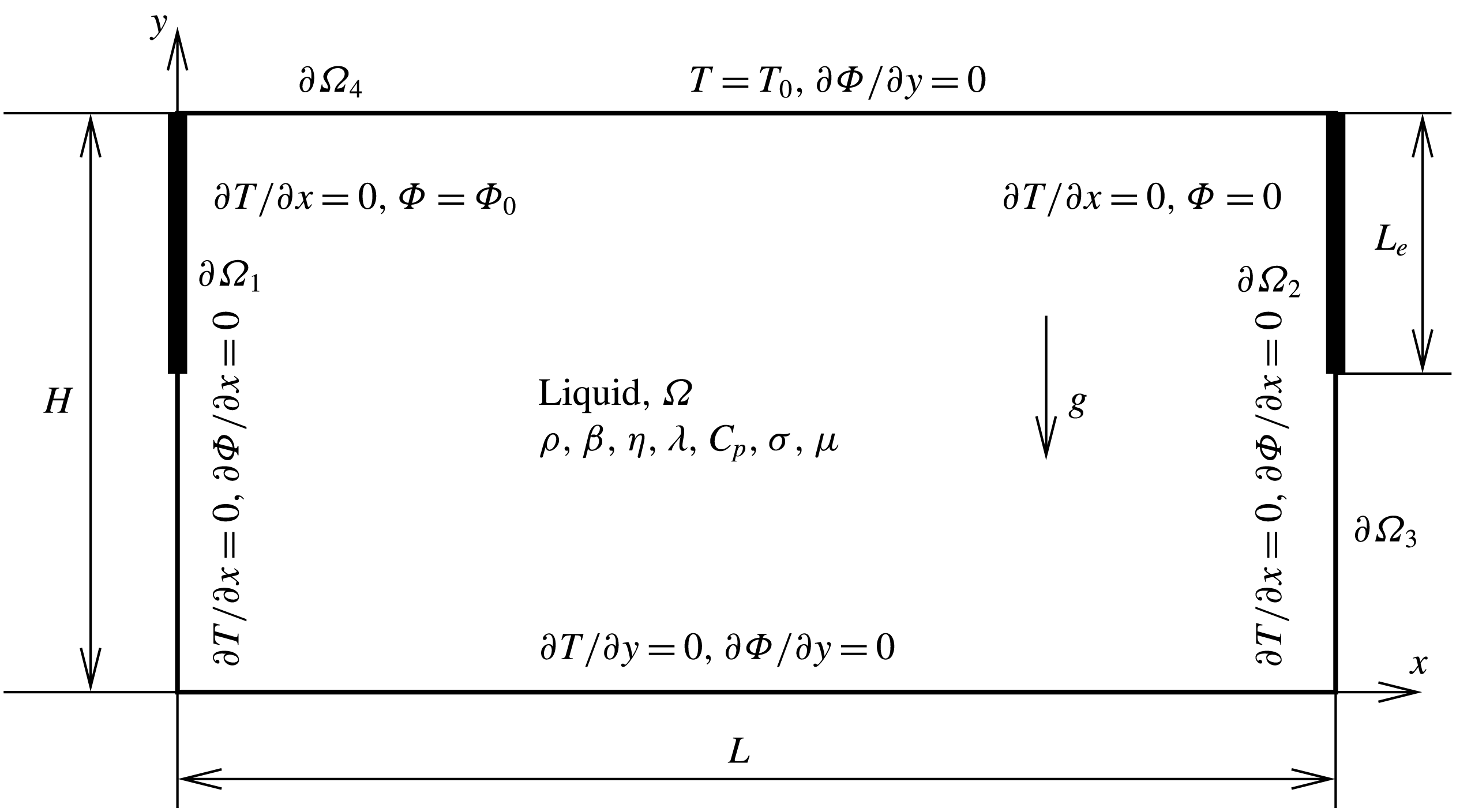
as shown in figure 1. The enclosure is reported to a Cartesian framework
 $(x,y)$
for which the unit vector along the
 $x$
-axis is
 $\boldsymbol{e}_{x}$
and
 $\boldsymbol{e}_{y}$
along the
 $y$
-axis. The electrodes are a fraction of the left and right vertical walls which provide the electric field. Their length is equal to
 $L_{e}$
as depicted in figure 1. The boundaries
 $\unicode[STIX]{x2202}\unicode[STIX]{x1D6FA}_{1}$
and
 $\unicode[STIX]{x2202}\unicode[STIX]{x1D6FA}_{2}$
correspond to the left and right electrodes, respectively, on which an electric potential designated by
 $\unicode[STIX]{x1D6F7}$
is applied. More accurately, the following Dirichlet conditions are imposed: on
 $\unicode[STIX]{x2202}\unicode[STIX]{x1D6FA}_{1}$
,
 $\unicode[STIX]{x1D6F7}=\unicode[STIX]{x1D6F7}_{0}$
and on
 $\unicode[STIX]{x2202}\unicode[STIX]{x1D6FA}_{2}$
,
 $\unicode[STIX]{x1D6F7}=0$
. The boundary
 $\unicode[STIX]{x2202}\unicode[STIX]{x1D6FA}_{3}$
composed by the rest of the vertical walls apart from electrodes and by the bottom horizontal wall is considered as an electric and thermal insulator. A uniform temperature
 $T_{0}$
is applied on the top of the enclosure
 $\unicode[STIX]{x2202}\unicode[STIX]{x1D6FA}_{4}$
. This boundary is also assumed to be an electric insulator. A no-slip boundary condition is applied on all boundaries.
Cavity, domain
 $\unicode[STIX]{x1D6FA}$
, filled with an electric liquid conductor. A potential is applied on vertical electrodes (boundaries
 $\unicode[STIX]{x2202}\unicode[STIX]{x1D6FA}_{1}$
and
 $\unicode[STIX]{x2202}\unicode[STIX]{x1D6FA}_{2}$
), while a temperature is applied on the boundary
 $\unicode[STIX]{x2202}\unicode[STIX]{x1D6FA}_{4}$
.

Before introducing the governing equations, the physical properties have to be discussed in the context of the glass melting process. The physical properties involved in the problem are given in figure 1, for which the density
 $\unicode[STIX]{x1D70C}$
is defined at the temperature
 $T_{0}$
. For a glass former liquid, the typical value of
 $\unicode[STIX]{x1D70C}$
is approximately
 $2300~\text{kg}~\text{m}^{-3}$
. The density variation with the temperature
 $T$
is taken into account in the framework of the Boussinesq approximation, characterized by the volumetric thermal dilatation coefficient
 $\unicode[STIX]{x1D6FD}$
close to
 $10^{-4}~\text{K}^{-1}$
. The dynamic viscosity
 $\unicode[STIX]{x1D702}$
depends strongly on temperature. Indeed, it is classically admitted that glass former liquids follow a Vogel–Fulcher–Tammann relation characterized by an exponential behaviour of the dynamic viscosity as a function of temperature (Scholze Reference Scholze1990). Typically for window glass, the dynamic viscosity changes from
 $10^{3}$
to 5 Pa s when the temperature increases from
 $1000~^{\circ }\text{C}$
to
 $1500~^{\circ }\text{C}$
. Taking into account this dependence does not change the main phenomena that we want to pinpoint in this work (Gramberg, Howell & Ockendon Reference Gramberg, Howell and Ockendon2007; Chiu-Webster, Hinch & Lister Reference Chiu-Webster, Hinch and Lister2008; Pigeonneau & Flesselles Reference Pigeonneau and Flesselles2012). Of course the thermal dependence prevails for accurate computations achieved for the design purpose on domains close to real industrial plants.
Heat transfer is characterized by thermal conductivity,
 $\unicode[STIX]{x1D706}$
, which must take into account the radiative contribution. More accurately, a glass former liquid is a semitransparent medium. In the limit where the radiative absorption is important, the radiative transfer can be seen as a Fourier flux for which the thermal conductivity is a function of the absolute temperature to the power three (see Viskanta & Anderson (Reference Viskanta and Anderson1975) for more details). Nevertheless, in this work,
 $\unicode[STIX]{x1D706}$
is assumed constant. For typical temperatures experienced by a glass former liquid in a furnace,
 $\unicode[STIX]{x1D706}$
is generally equal to
 $10~\text{W}~\text{m}^{-1}~\text{K}^{-1}{-}100~\text{W}~\text{m}^{-1}~\text{K}^{-1}$
. The specific heat capacity
 $C_{p}$
is approximately
 $1200~\text{J}~\text{kg}^{-1}~\text{K}^{-1}$
, meaning that the thermal diffusivity
 $\unicode[STIX]{x1D705}=\unicode[STIX]{x1D706}/(\unicode[STIX]{x1D70C}C_{p})$
is small (
 ${\sim}10^{-6}~\text{m}^{2}~\text{s}^{-1}$
). Consequently, the relevant feature for such liquid is that viscous diffusion is more efficient than thermal diffusion. In other words, the Prandtl number recalled later must be larger than one. Typically, this dimensionless number is approximately
 $10^{2}{-}10^{4}$
for glass former liquids.
Finally,
 $\unicode[STIX]{x1D70E}$
and
 $\unicode[STIX]{x1D707}$
, corresponding respectively to the electric conductivity and the magnetic permeability, are involved in the electromagnetic field. The electric conductivity is strongly related to the ion mobility in oxide glasses (Scholze Reference Scholze1990). It is expected that
 $\unicode[STIX]{x1D70E}$
increases with temperature according to the Arrhenius law. Nevertheless, the activation energy stays moderate. Therefore, the electric conductivity varies in the approximate range from
 $10~\text{S}~\text{m}^{-1}$
to
 $30~\text{S}~\text{m}^{-1}$
when
 $T$
is in the range
 $[1000,1400]^{\circ }\text{C}$
. Consequently, once again, this property is assumed to be constant in the following. Finally, we recall that the magnetic permeability
 $\unicode[STIX]{x1D707}$
is the product of the vacuum permeability,
 $\unicode[STIX]{x1D707}_{0}=4\unicode[STIX]{x03C0}\times 10^{-7}~\text{H}~\text{m}^{-1}$
, and the relative permeability
 $\unicode[STIX]{x1D707}_{r}$
. For common glasses used for thermal insulation applications,
 $\unicode[STIX]{x1D707}_{r}$
is close to 1, meaning that
 $\unicode[STIX]{x1D707}$
is quasiequal to the vacuum permeability.
Rigorously, the coupling between the fluid motion, heat transfer and electromagnetism has to be done with the Navier–Stokes, energy conservation and Maxwell equations. However, the problem can be greatly simplified. First, note that in practice to avoid fouling of the electrodes, an alternating current is provided with frequencies of approximately 10 Hz–100 Hz. Using typical values of electric conductivity and magnetic permeability, it may be shown that Faraday induction does not play a significant role, meaning that the electric field
 $\boldsymbol{E}$
derives from a scalar potential,
 $\unicode[STIX]{x1D6F7}$
, since
 $\unicode[STIX]{x1D735}\times \boldsymbol{E}=0$
. Ohm’s law, given by
 $$\begin{eqnarray}\displaystyle & \displaystyle \boldsymbol{J}=\unicode[STIX]{x1D70E}(\boldsymbol{E}+\boldsymbol{u}\times \boldsymbol{B}), & \displaystyle\end{eqnarray}$$
expresses that the current density
 $\boldsymbol{J}$
is proportional to the electric field and to the cross-product of the velocity
 $\boldsymbol{u}$
and the magnetic field
 $\boldsymbol{B}$
(Laplace force). The second contribution can be neglected because this term is quantified by the magnetic Reynolds number
 $$\begin{eqnarray}\displaystyle Re_{m}=Re\unicode[STIX]{x1D707}\unicode[STIX]{x1D70E}\unicode[STIX]{x1D708}, & & \displaystyle\end{eqnarray}$$
in which
 $Re$
is the Reynolds number and
 $\unicode[STIX]{x1D708}=\unicode[STIX]{x1D702}/\unicode[STIX]{x1D70C}$
is the kinematic viscosity. Due to the high viscosity the Reynolds number stays moderate (
 ${\sim}10^{-1}{-}1$
). Moreover, the small magnetic permeability leads to a magnetic Reynolds number smaller than one, meaning that the contribution of the Laplace force can be neglected.
The driving forces in such a problem are the buoyancy force due to thermal dilatation, proportional to
 $\unicode[STIX]{x1D70C}g\unicode[STIX]{x1D6FD}\unicode[STIX]{x0394}T$
, with
 $\unicode[STIX]{x0394}T$
the temperature range which will be quantified in the following, and the Lorentz force given by
 $\boldsymbol{J}\times \boldsymbol{B}$
. The ratio of the Lorentz to buoyancy forces is given by
 $$\begin{eqnarray}\displaystyle & \displaystyle \frac{||\boldsymbol{J}\times \boldsymbol{B}||}{\unicode[STIX]{x1D70C}g\unicode[STIX]{x1D6FD}\unicode[STIX]{x0394}T}=\frac{Ha^{2}}{Gr}, & \displaystyle\end{eqnarray}$$
with
 $Ha$
the Hartmann and
 $Gr$
the Grashof numbers, defined as follows:
 $$\begin{eqnarray}\displaystyle & \displaystyle Ha=\frac{\unicode[STIX]{x1D70E}\unicode[STIX]{x0394}\unicode[STIX]{x1D6F7}H}{\unicode[STIX]{x1D708}}\sqrt{\frac{\unicode[STIX]{x1D707}}{\unicode[STIX]{x1D70C}}}, & \displaystyle\end{eqnarray}$$
 $$\begin{eqnarray}\displaystyle & \displaystyle Gr=\frac{g\unicode[STIX]{x1D6FD}\unicode[STIX]{x0394}TH^{3}}{\unicode[STIX]{x1D708}^{2}}. & \displaystyle\end{eqnarray}$$
Since the source term in the energy equation is due to Joule dissipation, the range of variation of
 $\unicode[STIX]{x0394}T$
can be estimated by balancing heat diffusion with the Joule dissipation, which gives the order of magnitude of
 $\unicode[STIX]{x0394}T$
(see for more details appendix A):
 $$\begin{eqnarray}\displaystyle & \displaystyle \unicode[STIX]{x0394}T=\frac{\unicode[STIX]{x1D70E}\unicode[STIX]{x1D6F7}_{0}^{2}H^{2}}{2\unicode[STIX]{x1D706}L^{2}}. & \displaystyle\end{eqnarray}$$
The typical potential difference applied between electrodes is approximately 100 V, leading to typical values of Hartmann number less than one. Moreover, the range of temperature experienced by the liquid is close to
 $10^{3}~\text{K}$
. Consequently, the Grashof number is expected to be greater than
 $10^{3}$
, meaning that in general, for glass melting applications, Lorentz forces can be neglected. The same assumptions have been made in the previous works of Stanek (Reference Stanek1977), Choudhary (Reference Choudhary1986) and, more recently, Gopalakrishnan et al. (Reference Gopalakrishnan, Thess, Weidmann and Lange2010).
Under such conditions, the determination of the electric field in the liquid can be decoupled from heat and mass transfer. The electric potential will be determined by solving a Laplace equation.
The governing equations of motion are the Navier–Stokes equations with the gravitational body force due to the non-uniform temperature field coupled with the energy balance. This system of equations is called the Navier–Stokes–Fourier equations, according to Zeytounian (Reference Zeytounian2004). As mentioned above, Joule dissipation, which is proportional to the norm of the electric potential gradient to the power two, will be given by the resolution of the Laplace equation on
 $\unicode[STIX]{x1D6F7}$
.
The governing equations are normalized according to the usual method as detailed in appendix A. The spatial coordinates are normalized by the height of the cavity, the time
 $t$
by
 $H^{2}/\unicode[STIX]{x1D705}$
, the velocity
 $\boldsymbol{u}$
by
 $\sqrt{\unicode[STIX]{x1D6FD}\unicode[STIX]{x0394}TgH}$
and the temperature is written as follows:
 $$\begin{eqnarray}\displaystyle & \displaystyle \unicode[STIX]{x1D703}=\frac{T-T_{0}}{\unicode[STIX]{x0394}T}, & \displaystyle\end{eqnarray}$$
with
 $\unicode[STIX]{x0394}T$
given by (2.6). Consequently, the balance equations are given by
 $$\begin{eqnarray}\displaystyle & \displaystyle \unicode[STIX]{x1D735}\boldsymbol{\cdot }\boldsymbol{u}=0, & \displaystyle\end{eqnarray}$$
 $$\begin{eqnarray}\displaystyle & \displaystyle \frac{1}{Pr}\frac{\unicode[STIX]{x2202}\boldsymbol{u}}{\unicode[STIX]{x2202}t}+\sqrt{\frac{Ra}{Pr}}\boldsymbol{u}\boldsymbol{\cdot }\unicode[STIX]{x1D735}\boldsymbol{u}=-\unicode[STIX]{x1D735}p+\unicode[STIX]{x1D6FB}^{2}\boldsymbol{u}+\sqrt{\frac{Ra}{Pr}}\unicode[STIX]{x1D703}\boldsymbol{e}_{y}, & \displaystyle\end{eqnarray}$$
 $$\begin{eqnarray}\displaystyle & \displaystyle \frac{\unicode[STIX]{x2202}\unicode[STIX]{x1D703}}{\unicode[STIX]{x2202}t}+\sqrt{PrRa}\unicode[STIX]{x1D735}\unicode[STIX]{x1D703}\boldsymbol{\cdot }\boldsymbol{u}=\unicode[STIX]{x1D6FB}^{2}\unicode[STIX]{x1D703}+2L^{2}\left(\unicode[STIX]{x1D735}\unicode[STIX]{x1D6F7}\right)^{2}, & \displaystyle\end{eqnarray}$$
 $$\begin{eqnarray}\displaystyle & \displaystyle \unicode[STIX]{x1D6FB}^{2}\unicode[STIX]{x1D6F7}=0, & \displaystyle\end{eqnarray}$$
in which
 $\boldsymbol{u}$
is the velocity,
 $p$
the pressure taking into account the hydrostatic contribution. The Rayleigh number
 $Ra$
and the Prandtl number
 $Pr$
are given by
 $$\begin{eqnarray}\displaystyle & \displaystyle Ra=\frac{g\unicode[STIX]{x1D6FD}\unicode[STIX]{x0394}TH^{3}}{\unicode[STIX]{x1D708}\unicode[STIX]{x1D705}}, & \displaystyle\end{eqnarray}$$
 $$\begin{eqnarray}\displaystyle & \displaystyle Pr=\frac{\unicode[STIX]{x1D708}}{\unicode[STIX]{x1D705}}. & \displaystyle\end{eqnarray}$$
Equations (2.8)–(2.10) arise from the mass, the momentum and the energy balances. The Laplace equation (2.11) comes from the free divergence of the electric current, which is given by Ohm’s law. In the energy equation (2.10), the viscous dissipation source term has been neglected. Note that
 $L$
in (2.10) is the dimensionless length of the enclosure, i.e. equal to 2 in the present case.
Note that reversal of the boundary conditions on the electric potential does not change the Joule dissipation term. Moreover, boundary conditions on temperature and velocity respect the symmetry about the middle axis of the enclosure. Consequently, left–right symmetry is fulfilled in the present problem. Nevertheless, up–down symmetry currently observed in a cavity differentially heated end walls (Batchelor Reference Batchelor1954; de Vahl Davis Reference de Vahl Davis1983) is not valid with our thermal boundary conditions applied on the top and bottom walls.
This set of equations is solved numerically using our own solver written with the Rheolef C++ library (Saramito Reference Saramito2015a ). Since the electric potential and the Joule dissipation do not depend on time, they are computed at the beginning of the numerical procedure using a classical Galerkin formulation with a second-order polynomial. For Navier–Stokes–Fourier equations, a discontinuous Galerkin finite element method has been developed with the same library (Saramito Reference Saramito2015b ). The numerical method has been designed to be fully implicit. The nonlinear Navier–Stokes problem is numerically solved using a damped Newton method (see (Saramito Reference Saramito2015b ) for more details).
The initial conditions are the following:
 $$\begin{eqnarray}\displaystyle \left.\begin{array}{@{}l@{}}\boldsymbol{u}(\boldsymbol{x},0)=0,\\ \unicode[STIX]{x1D703}(\boldsymbol{x},0)=0,\end{array}\right\}\forall ~\boldsymbol{x}\in \unicode[STIX]{x1D6FA}, & & \displaystyle\end{eqnarray}$$
which consider that the fluid is at rest with a uniform temperature equal to the value imposed at the top wall. From these initial conditions, the unsteady problem is solved until time convergence, or for a certain time when time convergence is not observed. The same second-order polynomial is used for the temperature, pressure and velocity fields. The time derivatives are determined using the backward differential formula at the second order (BDF-2), which ensures that the numerical solver is unconditionally stable (Süli & Mayers Reference Süli and Mayers2003). The Navier–Stokes solver has been previously tested on the driven cavity benchmark, proving a high level of accuracy of the numerical implementation (Saramito Reference Saramito2016). The time convergence is checked by computing the
 $L^{2}$
-norm of the time derivatives of velocity and temperature evaluated by the backward differential formula at the second order. The steady state is considered reached when the norms of time derivatives of both velocity and temperature are below
 $10^{-10}$
. Since this numerical technique is now well known, no further details are provided. People interested in this numerical method can find all details in the textbook of Di Pietro & Ern (Reference Di Pietro and Ern2012).
The next section is devoted to preliminary results obtained when the electrode length is equal to the cavity height, i.e.
 $L_{e}=1$
. In § 4, attention will be drawn to the situation where
 $L_{e}\neq 1$
.
3 Preliminary results with
 $L_{e}=1$

To control the numerical accuracy of our solver, computations have been performed when
 $L_{e}=1$
, leading to a uniform source term in the temperature equation. It is possible to compare such a situation with previous works performed theoretically or numerically.
Numerical simulations have been done in a rectangular cavity with a length equal to twice its height. The dimensionless mesh size is equal to
 $5\times 10^{-2}$
, giving 1868 finite elements. The range of Rayleigh number is taken in
 $[1600,2000]$
and three values of Prandtl number have been studied:
 $Pr=1$
,
 $10$
and
 $10^{2}$
. During each numerical simulation, the maximum of the Euclidean velocity norm found in the enclosure at every time step is recorded. Due to the normalization proposed above and proved in appendix A, numerical values of the velocity have to be multiplied by the square root of the Grashof number to be equal to a Reynolds number and by
 $\sqrt{RaPr}$
to be equivalent to a Péclet number given by
 $Pe=RePr$
.
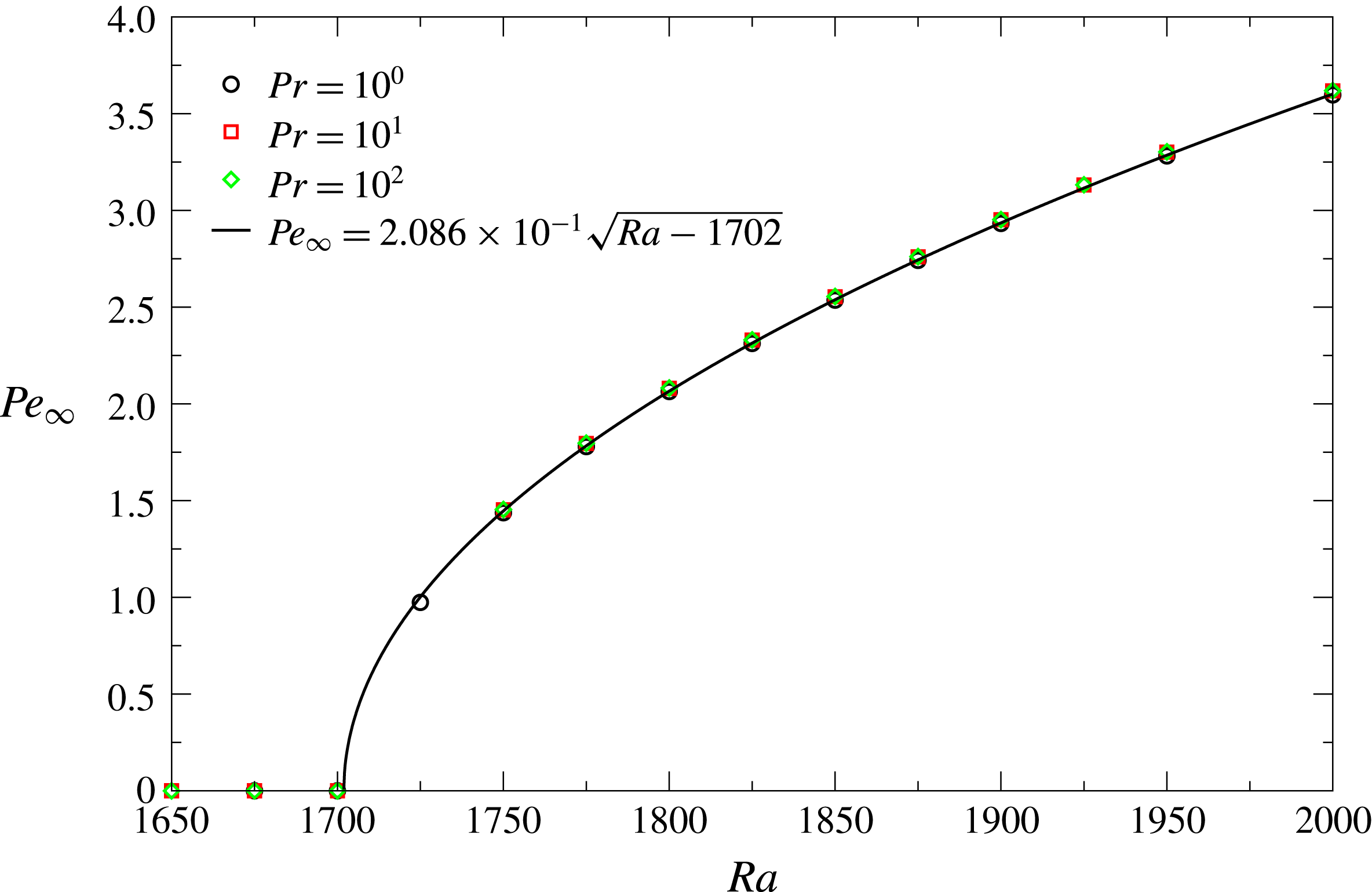
Figure 2 depicts the maximum of the Péclet number, obtained in the steady-state regime and designated as
 $Pe_{\infty }$
, as a function of the Rayleigh number. As expected, the threshold of convection is not modified when the Prandtl number changes (Krishnamurti Reference Krishnamurti1973). Moreover, the amplitude of convection measured in term of
 $Pe_{\infty }$
is the same whatever the Prandtl number, demonstrating that the relevant parameter to characterize the motion in the cavity is the Péclet number. This fact is similar to previous results obtained on horizontal convection by Pigeonneau & Flesselles (Reference Pigeonneau and Flesselles2012), who demonstrated that when the Prandtl number is larger than one, this dimensionless number becomes irrelevant.
 $Pe_{\infty }$
as a function of
 $Ra$
for
 $L=2$
,
 $L_{e}=1$
and
 $Pr=1$
,
 $10$
and
 $100$
obtained with a mesh size equal to
 $h=5\times 10^{-2}$
.

The velocity in the cavity becomes non-null above a critical Rayleigh number
 $Ra_{cr}$
. Above
 $Ra_{cr}$
,
 $Pe_{\infty }$
behaves as the square root of
 $Ra-Ra_{cr}$
, as expected in a supercritical bifurcation (Manneville Reference Manneville2004). From the numerical results, the nonlinear regression has been performed assuming the square root feature to determine
 $Ra_{cr}$
. The curve obtained by fitting is plotted in figure 2. From this nonlinear regression, the critical Rayleigh number has been found to be
 $1702$
. To control the spatial resolution, we performed the same numerical computations for
 $Pr=1$
with a mesh size equal to
 $2.5\times 10^{-2}$
, giving 7394 finite elements. We do not observe any difference from the previous spatial resolution on
 $Ra_{cr}$
. Our critical Rayleigh number is larger than the solution given for a linear stability achieved in a periodic domain without vertical walls, for which Kulacki & Goldstein (Reference Kulacki and Goldstein1975) found a critical Rayleigh number equal to
 $1386$
. The finite domain and the no-slip boundary condition at each wall constrain the fluid to be at rest. Consequently, it is expected to find a larger threshold value. The critical Rayleigh number obtained here is close to the value determined numerically by Sugilal et al. (Reference Sugilal, Wattal and Iyer2005) in the same geometry and conditions. These authors employed a finite volume method with a uniform mesh size equal to
 $1/60$
in both the space directions. They found a critical Rayleigh number equal to
 $1650$
. Nevertheless, no effort was made to study the mesh convergence in that contribution.
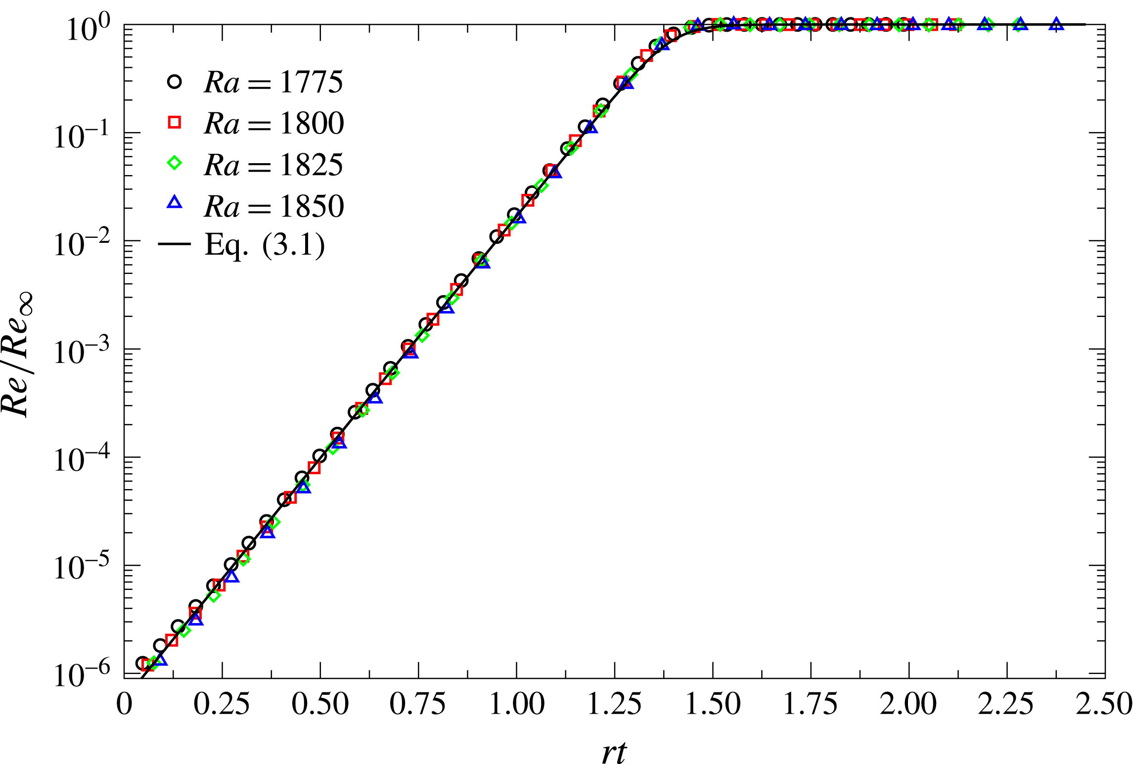
Figure 3 plots the time behaviour of the Reynolds number divided by the steady-state value for four Rayleigh numbers larger than the critical value in an enclosure of aspect ratio equal to 2. The mesh size is
 $h=5\times 10^{-2}$
and the Prandtl number is equal to one. As expected in the case of a supercritical bifurcation, after an exponential growth, the amplitude of the velocity reaches the steady-state limit.
 $Re/Re_{\infty }$
as a function of
 $rt$
for
 $L=2$
,
 $L_{e}=1$
,
 $Pr=1$
and for four Rayleigh numbers larger than the critical value.

This kind of behaviour can be described by the following equation (Manneville Reference Manneville2004):
 $$\begin{eqnarray}\displaystyle & \displaystyle \frac{Re}{Re_{\infty }}=\frac{\unicode[STIX]{x1D6FC}e^{\unicode[STIX]{x1D6FD}rt}}{\sqrt{1+\unicode[STIX]{x1D6FC}^{2}\text{e}^{2\unicode[STIX]{x1D6FD}rt}}}, & \displaystyle\end{eqnarray}$$
for which
 $\unicode[STIX]{x1D6FC}$
and
 $\unicode[STIX]{x1D6FD}$
are two constants of integration and the reduced control parameter
 $r$
is defined by
 $$\begin{eqnarray}\displaystyle & \displaystyle r=\frac{Ra-Ra_{cr}}{Ra_{cr}}. & \displaystyle\end{eqnarray}$$
The solid line in figure 3 corresponds to this solution with
 $\unicode[STIX]{x1D6FC}=5.71\times 10^{-7}$
and
 $\unicode[STIX]{x1D6FD}=10.295$
.
Figure 4 depicts the temperature field obtained for
 $Ra=1700$
,
 $1800$
,
 $1900$
and for
 $Pr=1$
. The temperature increases from the top to the bottom in the temperature range
 $[0,1]$
, which does not change significantly for the three values of
 $Ra$
, meaning that the values of isolines in figure 4 are equivalent between the three solutions. At
 $Ra=1700$
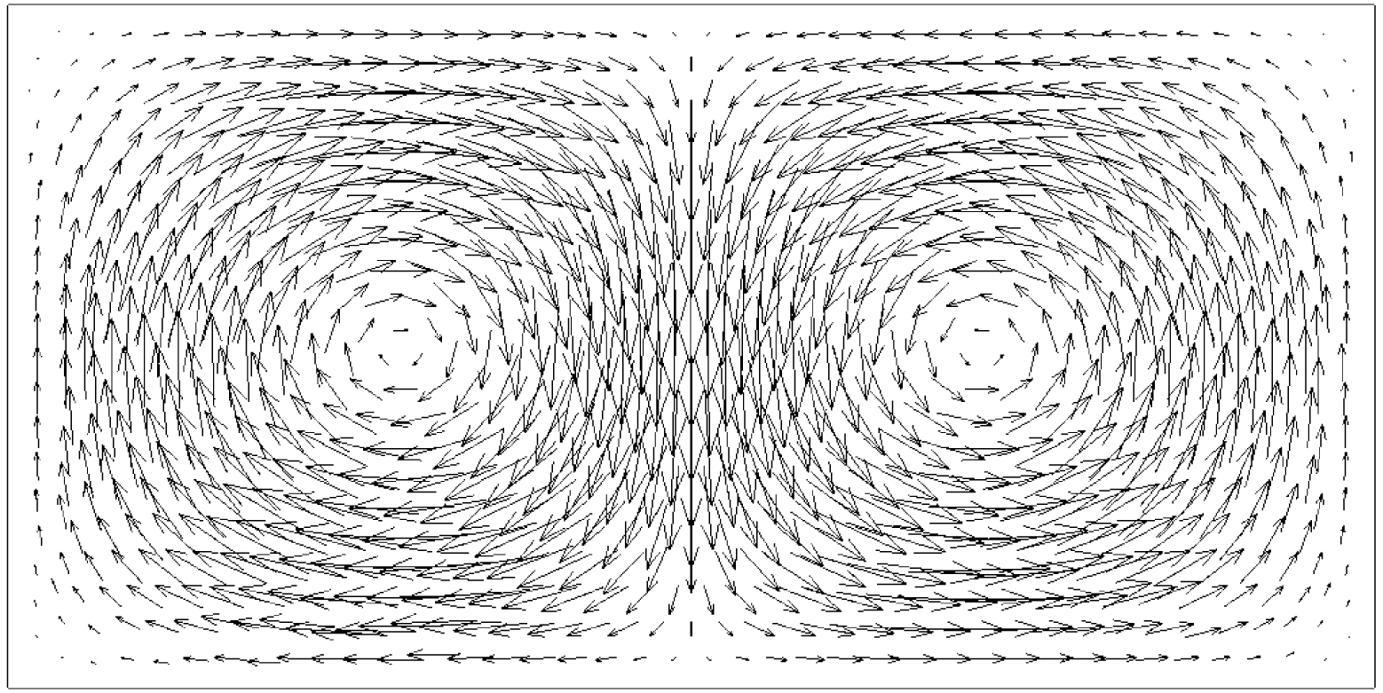
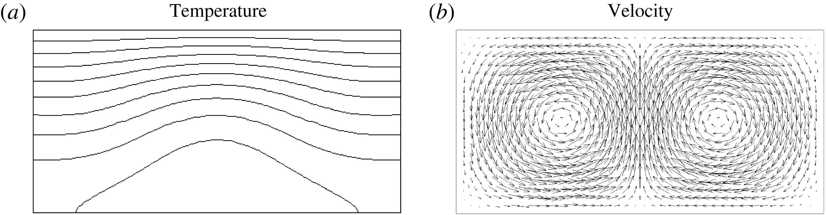
, which is just below the critical Rayleigh number established above, the fluid is at rest and the temperature is expected to be in agreement with a simple solution of a pure heat diffusion equation given by (A 2) (recalled in appendix A). Above the critical Rayleigh number, the temperature field is advected by fluid motion. In our solution, the velocity field is structured in two cells with a clockwise rotation for the left cell and an anticlockwise rotation for the right cell, as shown in figure 5. The maximum norm of the velocity is localized exactly in the middle of the enclosure and its value is equal to
 $6.7\times 10^{-2}$
. The two cell centres are on the line
 $y=1/2$
with a localization at
 $x=0.575$
for the left cell and
 $x=1.425$
for the right cell.
Isolines of temperature field in the enclosure for
 $L=2$
,
 $L_{e}=1$
and
 $Pr=1$
with a mesh size
 $h=5\times 10^{-2}$
at (a)
 $Ra=1700$
, (b)
 $Ra=1800$
and (c)
 $Ra=1900$
. Ten isolines equally spaced between 0 (on the top boundary) and 1 (on the bottom boundary) have been drawn on each plot.

It is noteworthy that the sense of rotation of the two cells is arbitrary and comes from the numerical perturbations that arise, for instance, from small mesh anisotropy. Theoretically, both directions of rotation are possible. To examine this point, a numerical simulation has been performed starting from the reverse of the steady-state solution obtained at
 $Ra=1900$
presented in figure 5. The steady-state solution of this second run is shown in figure 6, in which anticlockwise–clockwise cells are obtained. Whereas from the first solution, the Reynolds number obtained in the steady-state regime is equal to
 $2.92$
, the second solution gives a value equal to
 $2.76$
, showing that it is not purely the reverse of the first solution. This is due to the fact that the flow solution depends on the thermal features. Temperature isolines of this second solution depicted in figure 6(a) show that temperature is advected in the opposite direction in comparison to the solution given in figure 4(c). Due to the boundary conditions on
 $\unicode[STIX]{x1D703}$
between the bottom and top walls, up and down symmetry does not exist. The same observation has been underlined by Bergeon et al. (Reference Bergeon, Henry, Behadid and Tuckerman1998), who investigated Marangoni convection. Consequently, the bifurcation observed here should be a transcritical bifurcation for which one branch of the solution is supercritical and the second branch is subcritical.
Velocity field in the enclosure for
 $L=2$
,
 $L_{e}=1$
and
 $Pr=1$
with a mesh size
 $h=5\times 10^{-2}$
at
 $Ra=1900$
.

Steady-state solution with anticlockwise–clockwise cells obtained by reversing the solution with clockwise–anticlockwise cells for
 $Ra=1900$
. In (a) ten temperature isolines are equally spaced between 0 (on the top boundary) and 1 (on the bottom boundary).

In classical Rayleigh–Bénard convection, the thermal flux on boundaries where the temperature is imposed is usually taken to define the Nusselt number. Here, due to the presence of the source term and the energy conservation, the thermal gradient integrated over the top boundary is imposed and cannot be used to define the Nusselt number. According to Roberts (Reference Roberts1967) and Thirlby (Reference Thirlby1970) (see also Goluskin (Reference Goluskin2016)), the average temperature over the cavity length is introduced as follows:
 $$\begin{eqnarray}\displaystyle & \displaystyle \langle \unicode[STIX]{x1D703}\rangle (y,t)=\frac{1}{L}\int _{0}^{L}\unicode[STIX]{x1D703}(x,y,t)\,\text{d}x. & \displaystyle\end{eqnarray}$$
The Nusselt number is seen as the ratio of the average temperature at the bottom wall without convection to the average temperature at the same location with convection. Since for a uniform volume source term, the temperature at the bottom wall is equal to one, the Nusselt number is defined by
 $$\begin{eqnarray}\displaystyle & \displaystyle Nu=\frac{1}{\langle \unicode[STIX]{x1D703}\rangle (0,t)}. & \displaystyle\end{eqnarray}$$
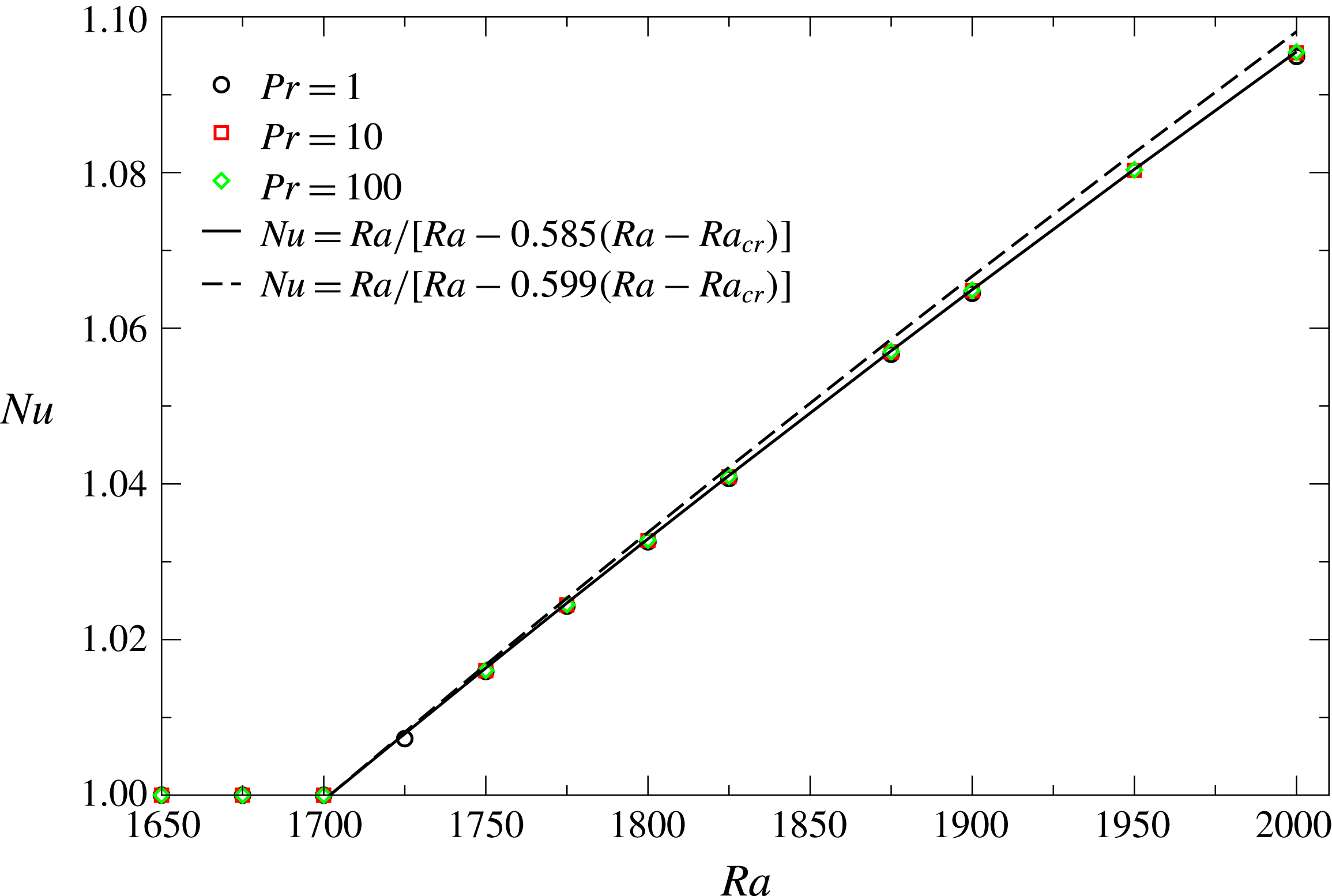
Figure 7 plots the Nusselt number as a function of Rayleigh number for three Prandtl numbers. Below
 $Ra_{cr}$
, the Nusselt number is obviously equal to one since the fluid is at rest. Above
 $Ra_{cr}$
,
 $Nu$
behaves quasilinearly with
 $Ra$
. The increase of the Nusselt number is due to the decrease of the average temperature produced by the fluid motion. This is the main signature of this case in which, when fluid motion occurs, the temperature in the enclosure becomes more and more homogeneous with a decrease in the amplitude of the temperature range. More accurately, Thirlby (Reference Thirlby1970) proposed to describe the Nusselt number as follows:
 $$\begin{eqnarray}\displaystyle & \displaystyle Nu=\frac{Ra}{Ra-\unicode[STIX]{x1D6E4}(Ra-Ra_{cr})}, & \displaystyle\end{eqnarray}$$
in which the coefficient
 $\unicode[STIX]{x1D6E4}$
can be determined from the linear stability. Using the prediction of Roberts (Reference Roberts1967), Thirlby (Reference Thirlby1970) gave a value for
 $\unicode[STIX]{x1D6E4}=0.599$
. From our numerical results obtained with three values of the Prandtl number, a regression computation gives a value of
 $\unicode[STIX]{x1D6E4}=0.585$
. The solution obtained by the law given by (3.5) is provided as a solid line. To compare with the linear stability solution, we plot in figure 7 the solution of Thirlby (Reference Thirlby1970) with
 $\unicode[STIX]{x1D6E4}=0.599$
, showing that the two laws are close even if in our case the problem is described in a finite domain.
 $Nu$
as a function of
 $Ra$
for
 $L=2$
,
 $L_{e}=1$
and
 $Pr=1$
,
 $10$
and
 $100$
obtained with a mesh size equal to
 $h=2.5\times 10^{-2}$
.

Joule dissipation corresponding to
 $2L^{2}(\unicode[STIX]{x1D735}\unicode[STIX]{x1D6F7})^{2}$
in the enclosure for
 $L_{e}=2/3$
drawn using 16 colours equally spaced in the range
 $[0;5]$
.

These preliminary results show that our numerical method is very accurate in describing natural convection with a volumetric source term. The bifurcation occurring in this configuration has been very well reproduced, in agreement with the theoretical predictions already published. Now, we turn our attention to the situation where
 $L_{e}\neq 1$
, which is seldom studied.
4 Convective regimes and transitions for
$L_{e}\neq 1$

From the practical point of view, electrodes are often shorter than the height of the enclosure. To study the effect of shortening of the electrodes, numerical simulations have been performed by cutting electrodes symmetrically from the bottom of the enclosure.
4.1 Onset of convection for
$L_{e}<1$

In a case of electrodes shorter than the height of the enclosure, the electric potential field is a solution of a Laplace equation with mixed boundary conditions: Dirichlet conditions on each electrode (
 $\unicode[STIX]{x2202}\unicode[STIX]{x1D6FA}_{1}$
and
 $\unicode[STIX]{x2202}\unicode[STIX]{x1D6FA}_{2}$
in figure 1) and Neumann conditions on
 $\unicode[STIX]{x2202}\unicode[STIX]{x1D6FA}_{3}$
and
 $\unicode[STIX]{x2202}\unicode[STIX]{x1D6FA}_{4}$
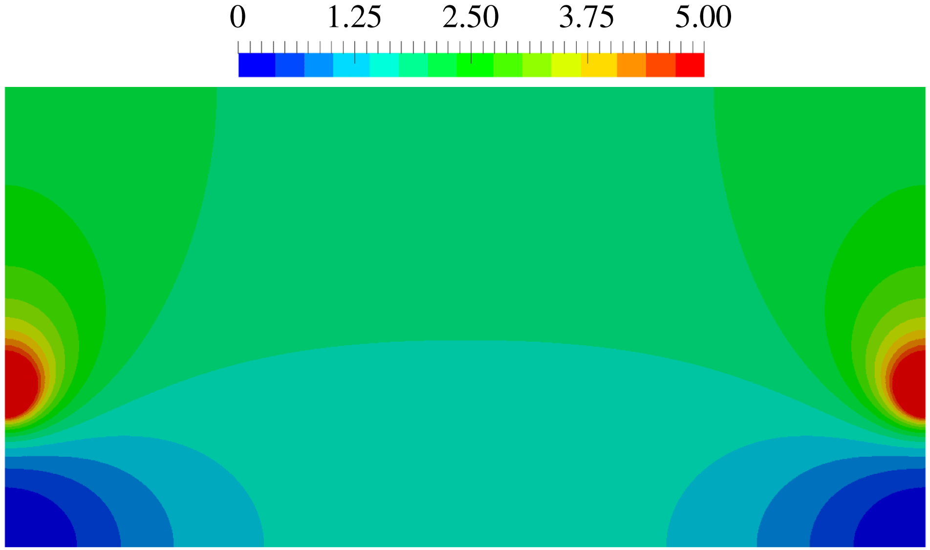
. As is well known in electrostatics, even if the potential field remains continuous at the extremity of each electrode, its gradient diverges, as does the Joule dissipation. Figure 8 depicts the source term equal to
 $2L^{2}(\unicode[STIX]{x1D735}\unicode[STIX]{x1D6F7})^{2}$
introduced in the heat transfer equation in the enclosure with a particular length
 $L_{e}=2/3$
. The dissipation clearly occurs principally close to the edge of each electrode.
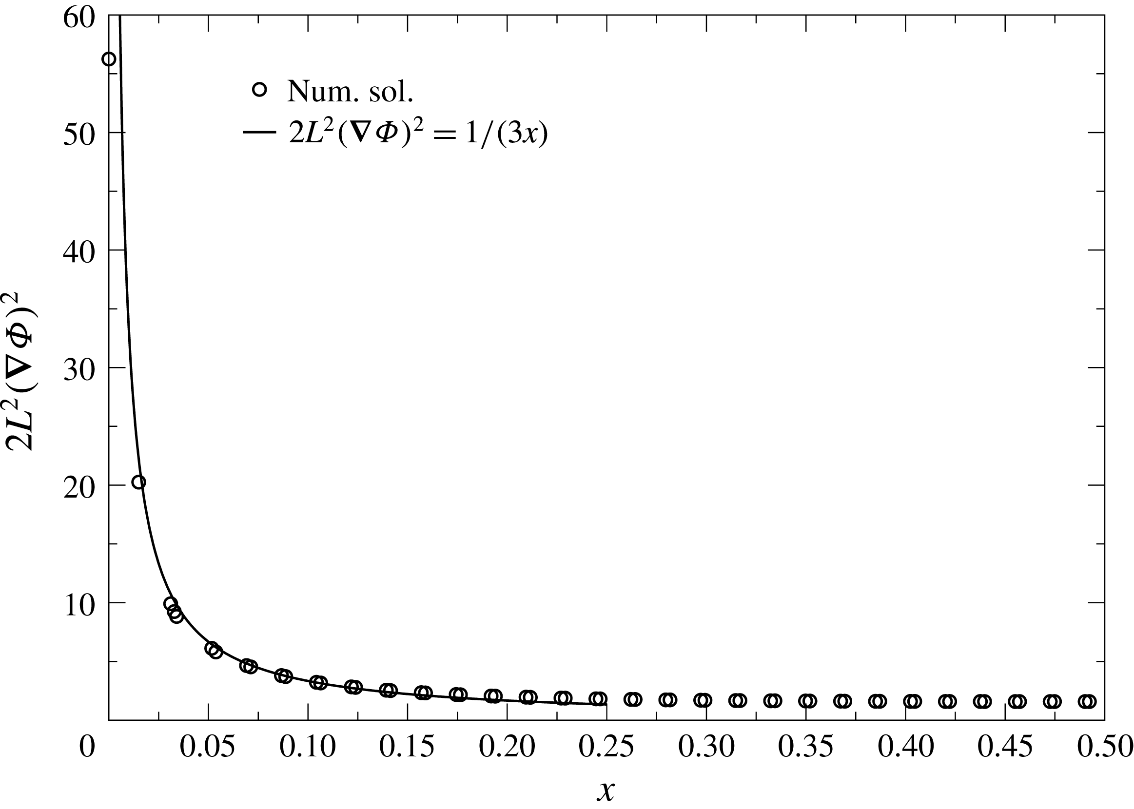
From the fundamental solution of the Laplace equation, the electric potential gradient diverges as
 $1/\sqrt{\unicode[STIX]{x1D71B}}$
, where
 $\unicode[STIX]{x1D71B}$
is the distance taken from the electrode edge, i.e.
 $y=1-L_{e}$
and
 $x=0$
or
 $L$
. Joule dissipation should diverge as
 $1/\unicode[STIX]{x1D71B}$
. Figure 9 plots the behaviour of the Joule dissipation source term as a function of
 $x$
from the left electrode edge. The numerical solution clearly shows that the source term diverges as expected, since the solid line in figure 9 is an approximate solution given by
 $1/(3x)$
. Nevertheless, even if the source term diverges, its integral stays finite.
Joule dissipation source term
 $2L^{2}(\unicode[STIX]{x1D735}\unicode[STIX]{x1D6F7})^{2}$
as a function of
 $x$
from the left electrode edge, i.e.
 $\boldsymbol{x}=(0,1-L_{e})$
in the enclosure for
 $L_{e}=2/3$
.

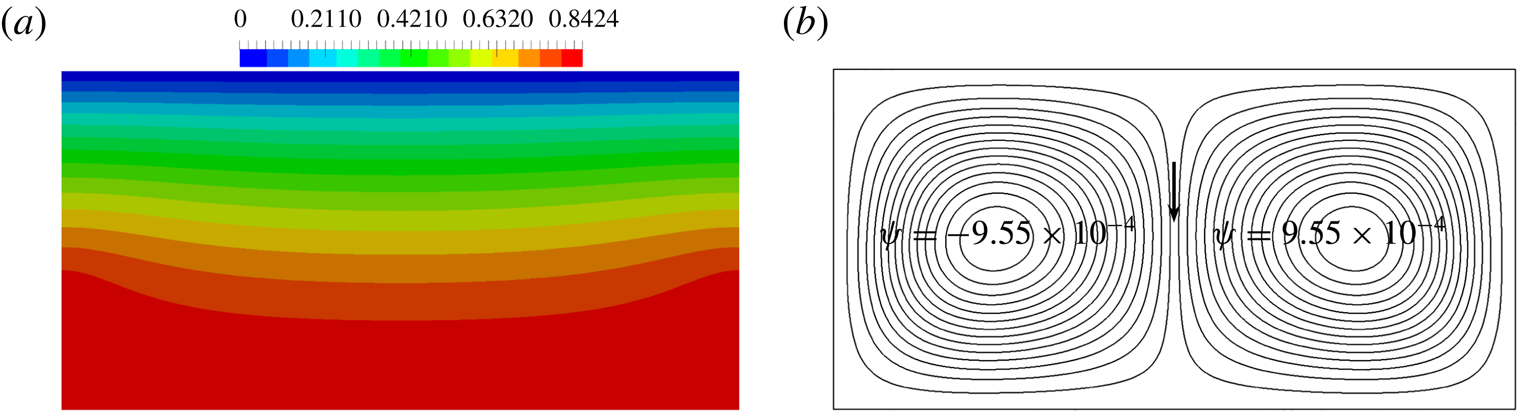
Temperature
 $\unicode[STIX]{x1D703}\in [0,0.84]$
(drawn using 16 colours equally spaced) and stream function
 $\unicode[STIX]{x1D713}$
obtained after time convergence for
 $Pr=1$
,
 $Ra=10^{2}$
and
 $L_{e}=2/3$
. Stream function isolines are equally spaced over 30 values in the range
 $[-9.55\times 10^{-4};9.55\times 10^{-4}]$
.

Since Joule dissipation is mainly concentrated in the neighbourhood of the electrode edge, Joule heating is more important around these two singular points. Figure 10(a) depicts the temperature field when the Rayleigh number is equal to
 $10^{2}$
and
 $Pr=1$
obtained after time convergence. Far from the vertical walls (in the middle of the enclosure),
 $\unicode[STIX]{x1D703}$
behaves as in the previous section. Nevertheless, the temperature increases close to the electrode edges, leading to a non-uniform temperature field. According to the criterion mentioned by Joseph (Reference Joseph1976, § 59), if the cross-product between the thermal gradient and the gravity is equal to zero, the motionless solution could exist. Clearly, this criterion is not fulfilled when
 $L_{e}<1$
. Consequently, motion is expected to appear without a threshold on the Rayleigh number. Figure 10(b) provides the stream function, denoted
 $\unicode[STIX]{x1D713}$
, when the Rayleigh number is equal to
 $10^{2}$
, which is smaller than the critical Rayleigh number established in the previous section. The stream function is obtained by solving a Poisson equation with a source term equal to the opposite of the vorticity. On the boundary,
 $\unicode[STIX]{x1D713}$
is imposed equal to zero. An arrow has been added in figure 10(b) to indicate the direction of the flow in the middle of the enclosure. Moreover, the values of
 $\unicode[STIX]{x1D713}$
are given close to the cell centres in figure 10(b). The sign of
 $\unicode[STIX]{x1D713}$
pinpoints the rotation direction of cells which are clockwise and anticlockwise for the left and right cells, respectively, noting that this result is not a particular branch of solutions. Indeed, the vorticity direction results from the cross-product
 $\unicode[STIX]{x1D735}\unicode[STIX]{x1D703}\times \boldsymbol{e}_{y}$
, as can be easily verified by taking the rotational of the momentum (2.9). The direction of the thermal gradient in the neighbourhood of the electrode edges being from the middle of the cavity towards the vertical walls, the rotation directions of the left and right cells are necessarily clockwise and anticlockwise, respectively.
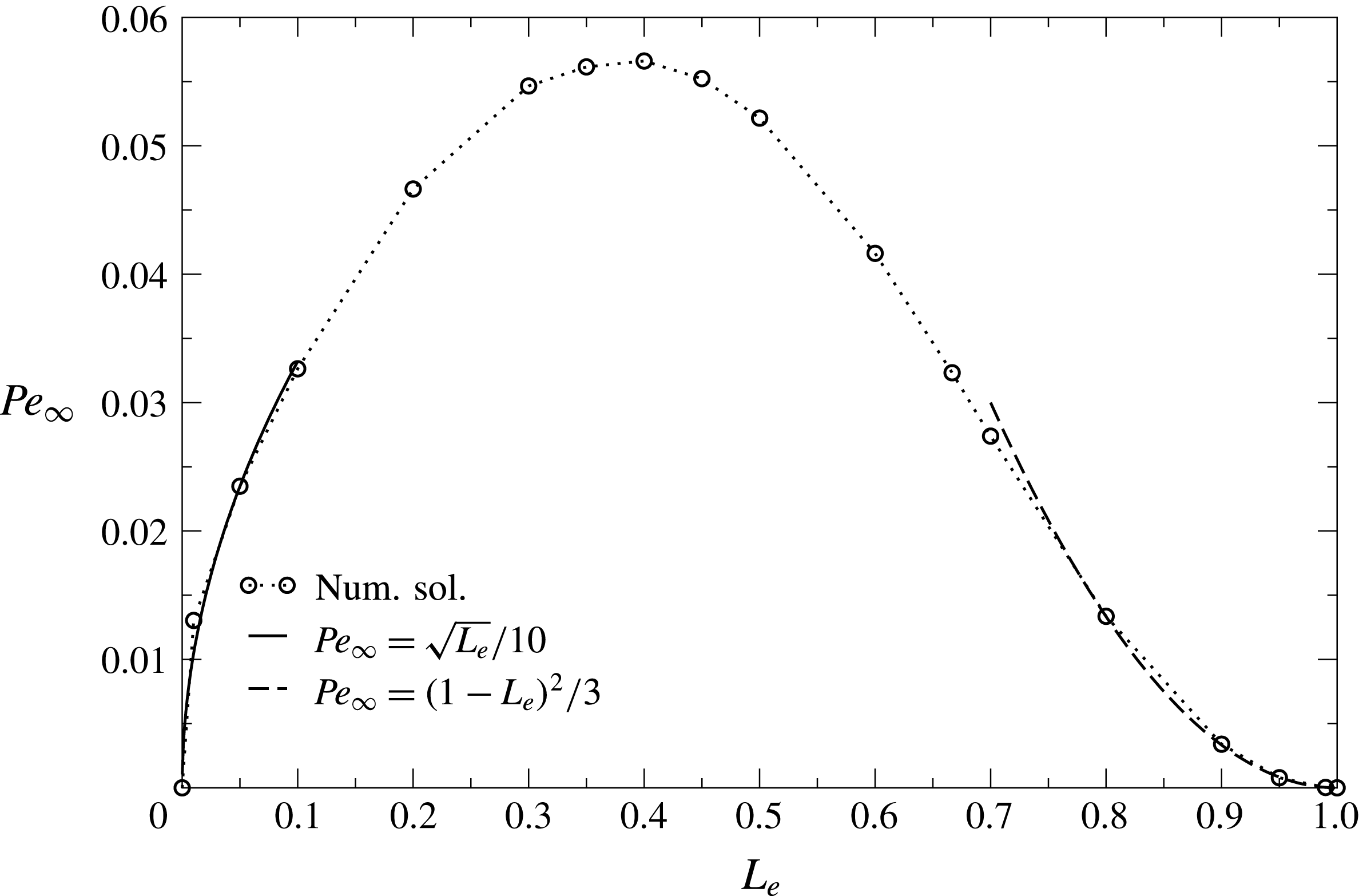
 $Pe_{\infty }$
versus
 $L_{e}$
for
 $Pr=1$
and
 $Ra=10^{2}$
.

To study the nature of the transition when the electrode length changes, numerical computations have been done for
 $L_{e}\in ]0,1[$
. The Prandtl number is set equal to 1 and the Rayleigh number is equal to
 $10^{2}$
. As shown in figure 11, when the electrode length is strictly shorter than one then the threshold in motion does not exist. The behaviour of the steady-state Péclet number as a function of
 $L_{e}$
proves this assertion. The non-monotonic profile observed in figure 11 means that an optimal electrode length exists that maximizes the flow intensity. The maximum of the kinematic intensity is observed for
 $L_{e}$
approximately equal to
 $0.4$
. This non-monotonic behaviour can be explained easily by noting that when the electrode lengths are equal to zero, the electric field disappears completely and the source term no longer exists. However, as soon as
 $L_{e}$
is not equal to zero, but still smaller than one, the electrodes can be seen as a source for the left electrode and a sink for the right electrode, leading to a strong Joule dissipation concentrated in the neighbourhood of the two top corners. Since the Joule dissipation scales as
 $1/\sqrt{\unicode[STIX]{x1D71B}}$
spreading over the electrode length, the Joule dissipation must be proportional to the square root of
 $L_{e}$
. Now, as the thermal field is proportional to the Joule dissipation term, and as the viscous force balances the buoyancy source term in the momentum equation, it is expected that the Péclet number is proportional to the square root of
 $L_{e}$
. To establish this approximation, the source term is integrated over the domain. But, as can easily be shown, the surface integral can be replaced by a linear integral over the electrode length. In the opposite situation, i.e. for long electrodes, the trend is different. As shown in figure 11, the Péclet number behaves as a square function of
 $1-L_{e}$
. This trend can be explained by noting that when the electrode lengths are close to 1, the electric potential field behaves as
 $A_{0}\sqrt{\unicode[STIX]{x1D71B}}+A_{1}\unicode[STIX]{x1D71B}^{2}$
. The first term comes from the solution behaviour close to the electrode edge, and the second term ensures that the gradient of
 $\unicode[STIX]{x1D6F7}$
vanishes on the bottom wall. To satisfy the boundary condition,
 $A_{0}$
must be proportional to
 $(1-L_{e})^{3/2}$
. Since the electric field gradient is concentrated at the electrode edge, scaling over a length approximately equal to
 $\sqrt{1-L_{e}}$
, the Joule source term must be proportional to
 $(1-L_{e})^{2}$
, which is exactly the scaling observed for the Péclet number.
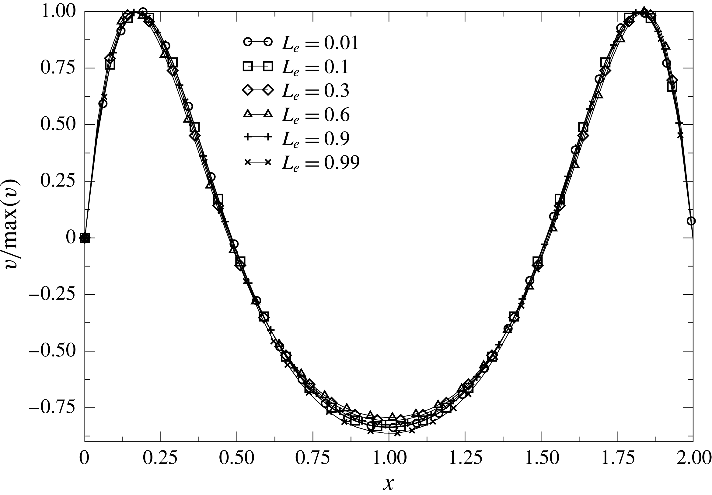
In figure 12, the
 $y$
-axis component of the velocity,
 $v$
, is plotted in the middle of the cavity (
 $y=0.5$
) as a function of
 $x$
for
 $Pr=1$
and
 $Ra=10^{2}$
for various electrode lengths. Since the intensity of the velocity field changes with
 $L_{e}$
, each profile is divided by the maximum of the
 $v$
component along the
 $x$
-axis. It is noteworthy that
 $v$
profiles obtained for all electrode lengths are very similar. Moreover, these profiles suggest that the two cells are such that the fluid rises up close to the electrodes, leading to clockwise and anticlockwise rotations for the left and right cells, respectively. Consequently, and in perfect agreement with our explanation given above using Joseph’s criterion, only one flow structure exists when
 $L_{e}$
becomes less than one.
 $v/\max (v)$
versus
 $x$
for
 $Pr=1$
and
 $Ra=10^{2}$
for various
 $L_{e}$
plotted for
 $y=0.5$
.

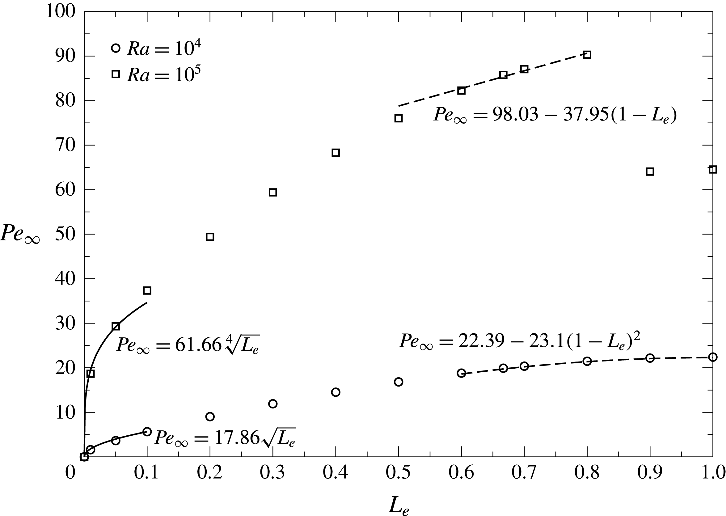
To go further, two other cases have been investigated for
 $Ra=10^{4}$
and
 $Ra=10^{5}$
, which are larger than the critical Rayleigh number of the previous section. The influence of the electrode length is also investigated for
 $Pr=1$
. For all numerical simulations, a steady-state regime is established. Figure 13 plots the Péclet number obtained after time convergence versus
 $L_{e}$
. The behaviour changes strongly in comparison with the previous results obtained at
 $Ra=10^{2}$
. Indeed, the Péclet number increases monotonically with
 $L_{e}$
for a Rayleigh number equal to
 $10^{4}$
. Using the previous analysis about the scaling of the Joule dissipation term, approximate solutions have been established for small
 $L_{e}$
and when
 $1-L_{e}\ll 1$
. Since the Rayleigh number is above the critical Rayleigh number it is clearly found that the flow does not vanish when
 $L_{e}$
goes to one.
 $Pe_{\infty }$
versus
 $L_{e}$
in the situation where
 $Ra=10^{4}$
or
 $10^{5}$
and for
 $Pr=1$
.

Numerical computations performed at
 $Ra=10^{5}$
provide new results. First, the increase of the Péclet number at small
 $L_{e}$
is sharper than the solution obtained at
 $Ra=10^{4}$
. This result can be easily explained by noting that, at large Rayleigh number, the flow is mainly driven by inertia. In this case, the balance in the momentum equation is achieved between the inertia term and the buoyancy source. Consequently, the velocity scales as the square root of temperature. Since the temperature is proportional to the Joule dissipation, it is expected that when the electrode length is small, the velocity and in consequence the Péclet number scales as
 $L_{e}$
to the power one fourth. The approximate solution given in figure 13 shows that this trend is verified.
The Péclet number presents a discontinuity between
 $L_{e}=0.8$
and
 $0.9$
. When
 $L_{e}\leqslant 0.8$
, the Péclet number increases quasilinearly with the electrode length, which once again can be explained using the scaling of the Joule dissipation term and the fact that the flow is in the inertial regime. To explain the discontinuity above
 $L_{e}=0.8$
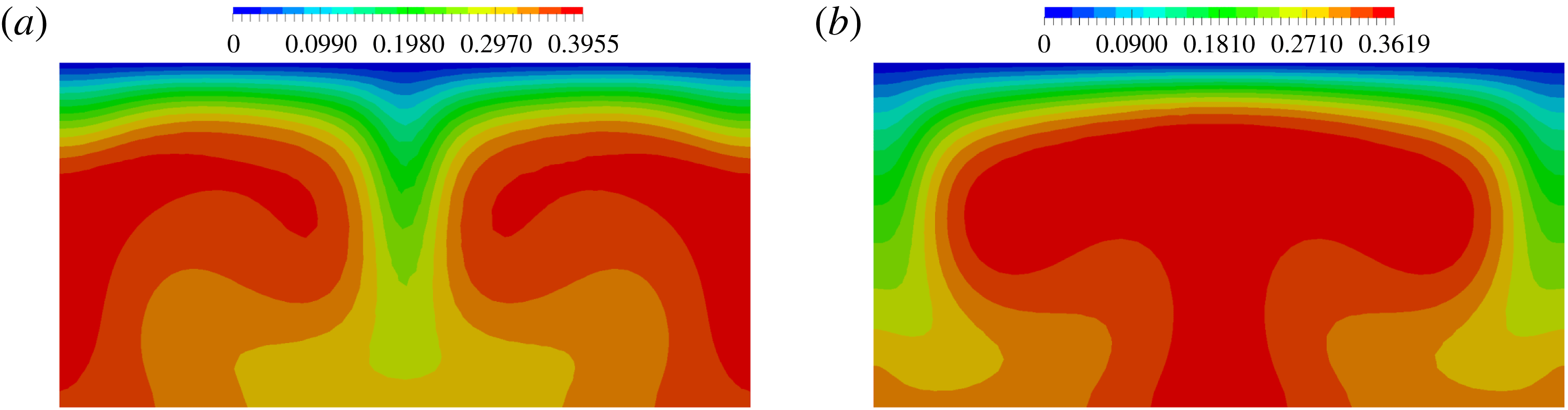
, it is necessary to explore the flow structures. The temperature field is plotted for
 $Ra=10^{5}$
,
 $Pr=1$
and when the electrode lengths are equal to
 $L_{e}=0.8$
and
 $L_{e}=0.9$
in figure 14. The temperature field for
 $L_{e}=0.8$
(panel a) is mainly driven by the convective transfer, meaning that the structure is composed by the down-flow in the middle of the enclosure, as already seen when
 $Ra=10^{2}$
. For
 $L_{e}=0.9$
(panel b), the flow structure shifts to another solution with up-flow in the middle of the cavity, creating a plume. Even if the down-flow structure is favoured, the up-flow structurecan be stable. This solution can be considered as a disconnected branch investigated in more detail by Torres et al. (Reference Torres, Henry, Komiya and Maruyama2014).
Temperature field obtained for
 $Ra=10^{5}$
,
 $Pr=1$
and for (a)
 $L_{e}=0.8$
and (b)
 $L_{e}=0.9$
. In (a),
 $\unicode[STIX]{x1D703}\in [0;0.39]$
is drawn using 16 colours equally spaced. In (b),
 $\unicode[STIX]{x1D703}\in [0;0.36]$
is drawn using 16 colours equally spaced.

In fact, we postpone careful analysis of the different structures to § 4.3 studied for a electrode length equal to
 $2/3$
. We will see that the up-flow structure giving rise to a plume is observed for small Prandtl number.
4.2 Steady-state convective regime for
$L_{e}=2/3$

In this subsection, the electrode lengths are set equal to
 $2/3$
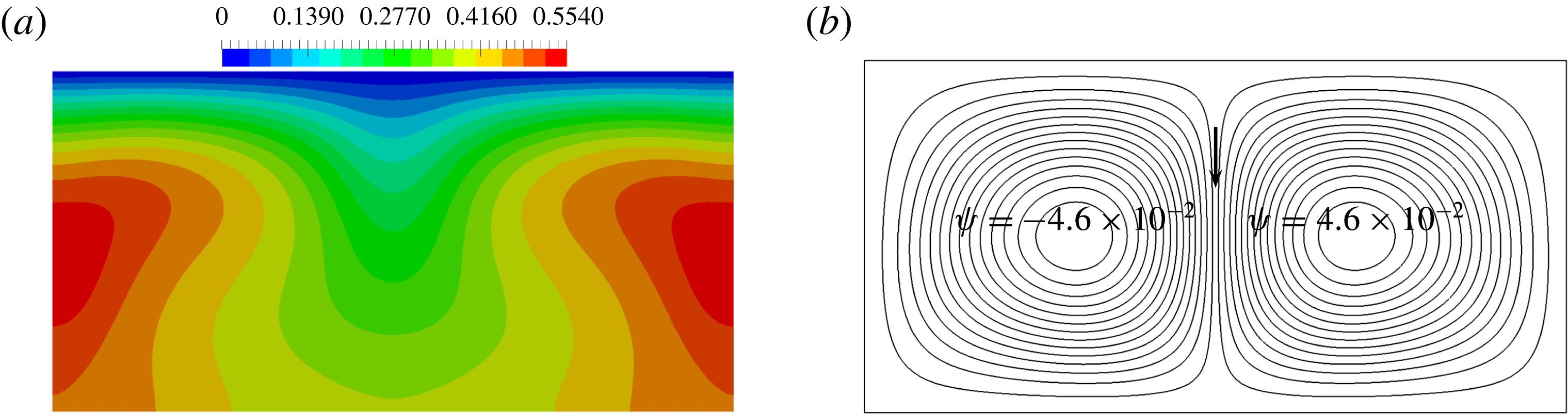
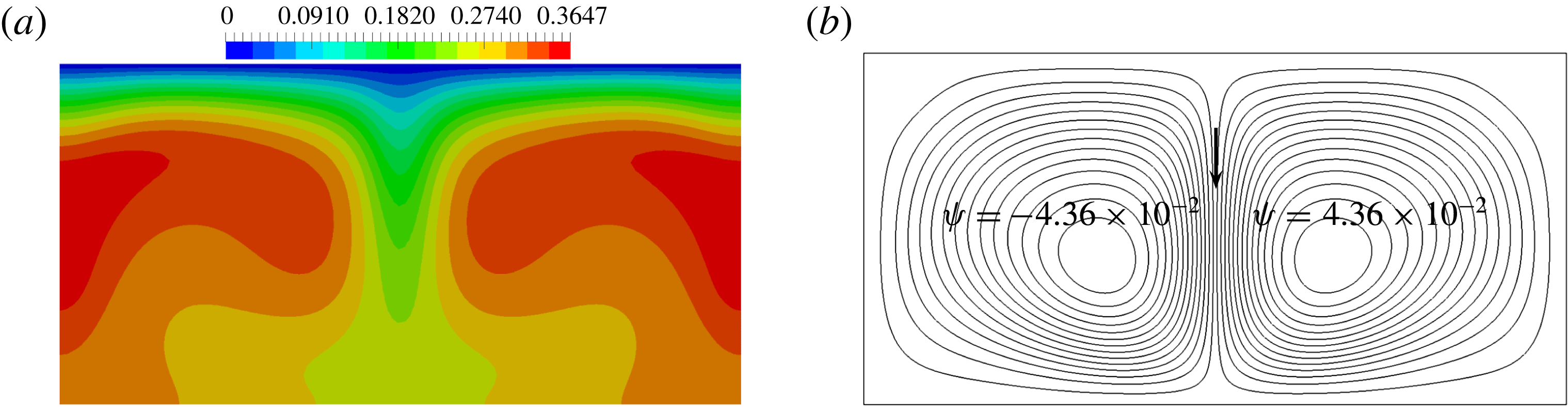
and we investigate the effect of the Rayleigh and Prandtl numbers on the heat and mass transfer. Results in this section are limited to the case for which the time convergence occurs. It is numerically observed that the range of Rayleigh numbers having a steady-state solution decreases when the Prandtl number increases. Figures 15 and 16 provide the temperature and the stream function for
 $Ra=10^{4}$
and
 $10^{5}$
, respectively. While the temperature field at
 $Ra=10^{2}$
, depicted in the previous subsection (figure 10), is close to the solution of a pure heat diffusion regime, the advection becomes stronger and stronger at
 $Ra=10^{4}$
and
 $10^{5}$
, to become a main contribution in the solution of the temperature field. When the Rayleigh number is equal to
 $10^{2}$
and
 $10^{4}$
, the centres of the two cells are located on the horizontal median of the enclosure. For
 $Ra=10^{5}$
, the vortex centres go down and become closer. In this situation, the flow structure is composed by two counter-rotating cells with the formation, in the middle of the enclosure, of a jet directed downwards.
(a)
 $\unicode[STIX]{x1D703}\in [0,0.55]$
mapped using 16 colours equally spaced; (b) stream function in the range
 $\pm 4.6\times 10^{-2}$
plotted with 30 isolines equally spaced obtained after time convergence for
 $Pr=1$
,
 $Ra=10^{4}$
and
 $L_{e}=2/3$
.

This observation of the flow structure indicates that at least two flow regimes exist in this problem, in agreement with the scaling analysis provided in appendix A. At low Rayleigh number, the flow regime is driven by heat conduction, whereas when the Rayleigh number is large, the temperature field is driven by convection.
(a)
 $\unicode[STIX]{x1D703}\in [0,0.36]$
mapped using 16 colours equally spaced; (b) stream function in the range
 $\pm 4.36\times 10^{-2}$
plotted with 30 isolines equally spaced obtained after time convergence for
 $Pr=1$
,
 $Ra=10^{5}$
and
 $L_{e}=2/3$
.

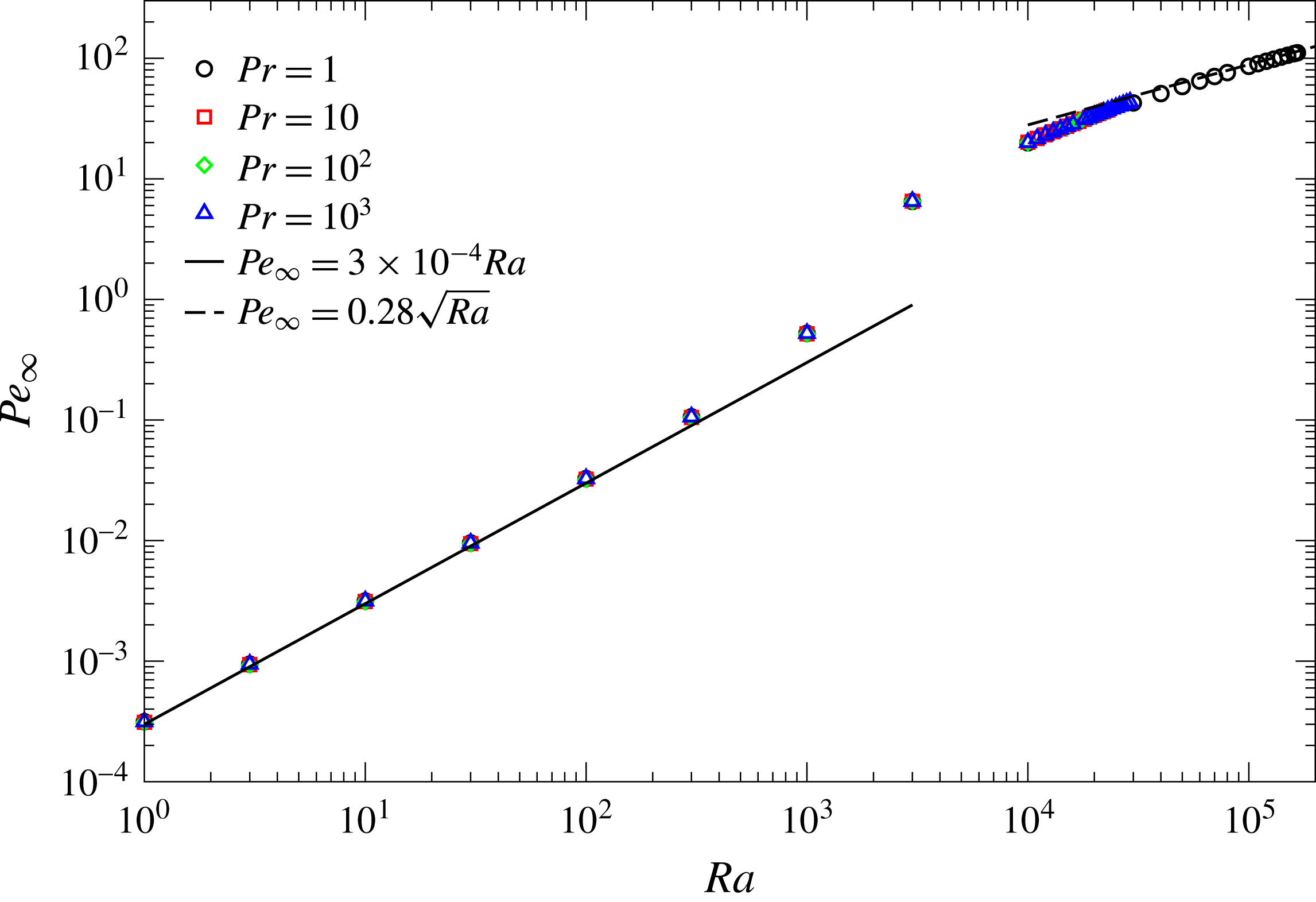
Figure 17 represents the steady-state Péclet number as a function of the Rayleigh number obtained for four Prandtl numbers. The two regimes are clearly established in figure 17. When the Rayleigh number is smaller than
 $10^{3}$
, the Péclet number behaves linearly as a function of Rayleigh number. The prefactor of the law depends on the length of the electrodes, following the results obtained in subsection 4.1. Above
 $Ra=10^{3}$
, the behaviour of
 $Pe_{\infty }$
changes towards a convective regime for which the Péclet number scales as the square root of the Rayleigh number. The first regime is in perfect agreement with the scaling established in appendix A, in which the Reynolds number is proportional to the Grashof number, implying that the Péclet number is linear with the Rayleigh number.
 $Pe_{\infty }$
as a function of
 $Ra$
for
 $L=2$
,
 $L_{e}=2/3$
and
 $Pr=1$
,
 $10$
,
 $10^{2}$
and
 $10^{3}$
obtained with a mesh size equal to
 $h=2.5\times 10^{-2}$
.

The second regime needs enlightenment. Indeed, if only the momentum equation is considered, as it was done in the scaling analysis, the balance of the inertial and the buoyancy forces predicts that the dimensionless velocity is constant, meaning that the Reynolds number should be proportional to
 $\sqrt{Ra/Pr}$
and consequently the Péclet number should scale as
 $\sqrt{RaPr}$
, which is not the case. To establish the right scaling, it is crucial to take into account the fact that the Prandtl number is larger than one. In this case, the inertia does not play a significant role in the momentum equation, meaning that the balance is once again achieved between the viscous and the buoyancy terms as follows:
 $$\begin{eqnarray}\displaystyle & \displaystyle u_{0}\sim \sqrt{\frac{Ra}{Pr}}\unicode[STIX]{x1D703}_{0}, & \displaystyle\end{eqnarray}$$
in which
 $u_{0}$
is the order of magnitude of the dimensionless velocity and
 $\unicode[STIX]{x1D703}_{0}$
the typical value of the reduced temperature. From the energy equation, the balance at large Rayleigh and Prandtl numbers is given by the convective term and the Joule dissipation such as
 $$\begin{eqnarray}\displaystyle & \displaystyle u_{0}\unicode[STIX]{x1D703}_{0}\sim \frac{S}{\sqrt{RaPr}}, & \displaystyle\end{eqnarray}$$
with
 $S$
an arbitrary constant. Using these two equations,
 $u_{0}$
is inversely proportional to the square root of the Prandtl number. Consequently, the Reynolds number scales as
 $\sqrt{Ra}/Pr$
and the Péclet number becomes proportional to the square root of the Rayleigh number, as is the case in figure 17. The two kinematic regimes are insensitive to the Prandtl number, as observed in figure 17, since the Péclet number does not change significantly when the Prandtl number increases from
 $1$
to
 $10^{3}$
.
 $x$
-axis average temperature profile (
 $y$
versus
 $\langle \unicode[STIX]{x1D703}\rangle$
) for (a)
 $Pr=1$
, (b)
 $Pr=10$
, (c)
 $Pr=10^{2}$
and (d)
 $Pr=10^{3}$
and for various Rayleigh numbers ranging between
 $10^{2}$
and
 $10^{5}$
for
 $L=2$
and
 $L_{e}=2/3$
obtained with a mesh size equal to
 $h=2.5\times 10^{-2}$
.

 $Nu$
as a function of
 $Ra$
for
 $L=2$
,
 $L_{e}=2/3$
and
 $Pr=1$
,
 $10$
,
 $10^{2}$
and
 $10^{3}$
obtained with a mesh size equal to
 $h=2.5\times 10^{-2}$
.

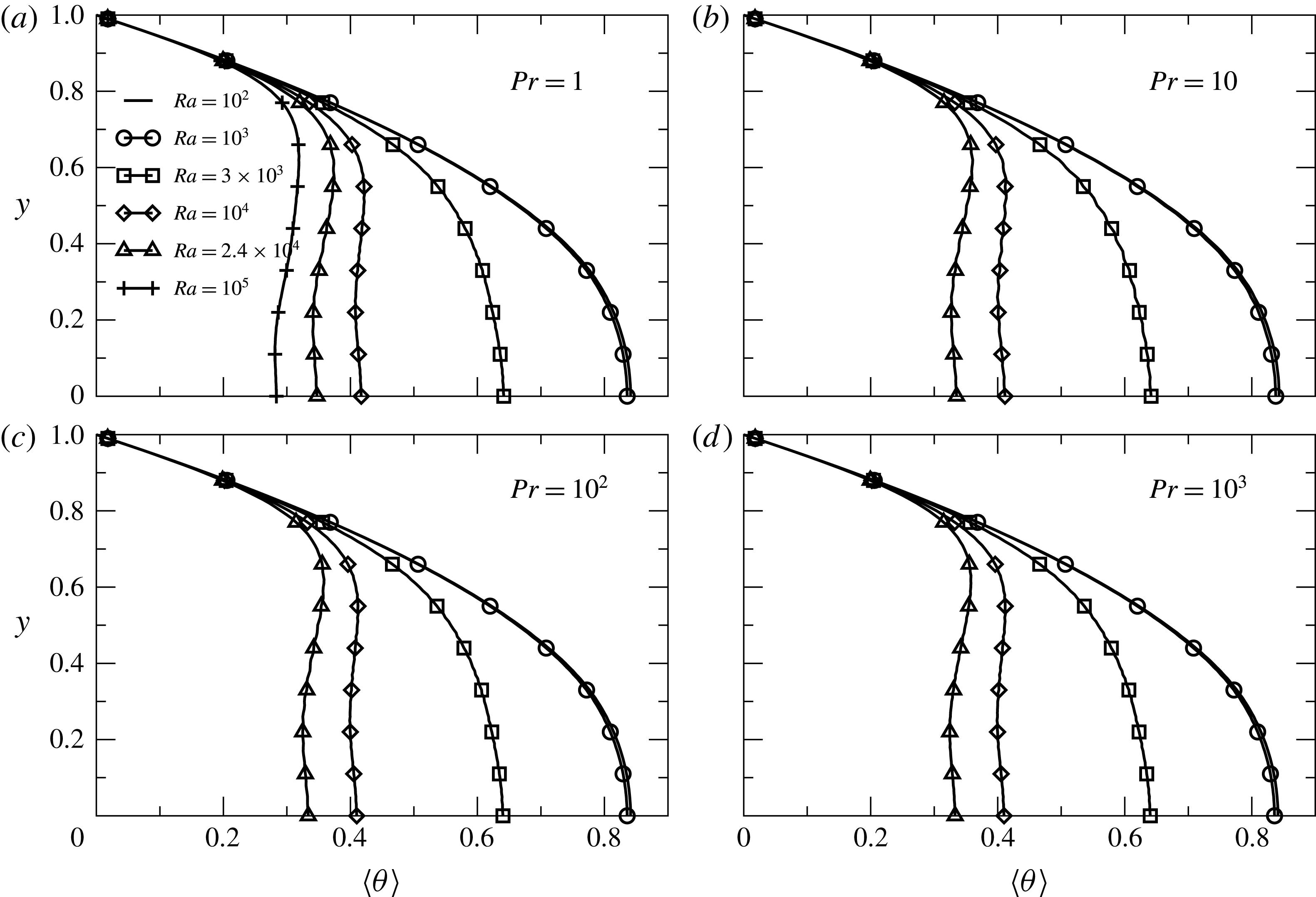
As shown in figure 10(b), figure 15(b) and figure 16(b), the temperature range becomes narrower when the Rayleigh number increases. To be more accurate in terms of thermal behaviour, the average temperature given by (3.3) is depicted in figure 18. Four Prandtl numbers have been investigated. The Rayleigh number ranges between
 $10^{2}$
and
 $2.4\times 10^{4}$
for Prandtl numbers larger than
 $1$
. The last value of
 $Ra$
has been chosen in order to have a steady-state solution. For
 $Pr=1$
, the largest value of the Rayleigh number is equal to
 $10^{5}$
. For the two small Rayleigh numbers, the average temperature profile over the
 $y$
-axis is close to the solution without convection. A sharp difference occurs when the Rayleigh number is larger than
 $10^{3}$
. The temperature profile becomes increasingly flat far away the top horizontal wall. It is noteworthy that the temperature profiles are very similar for the four Prandtl numbers.
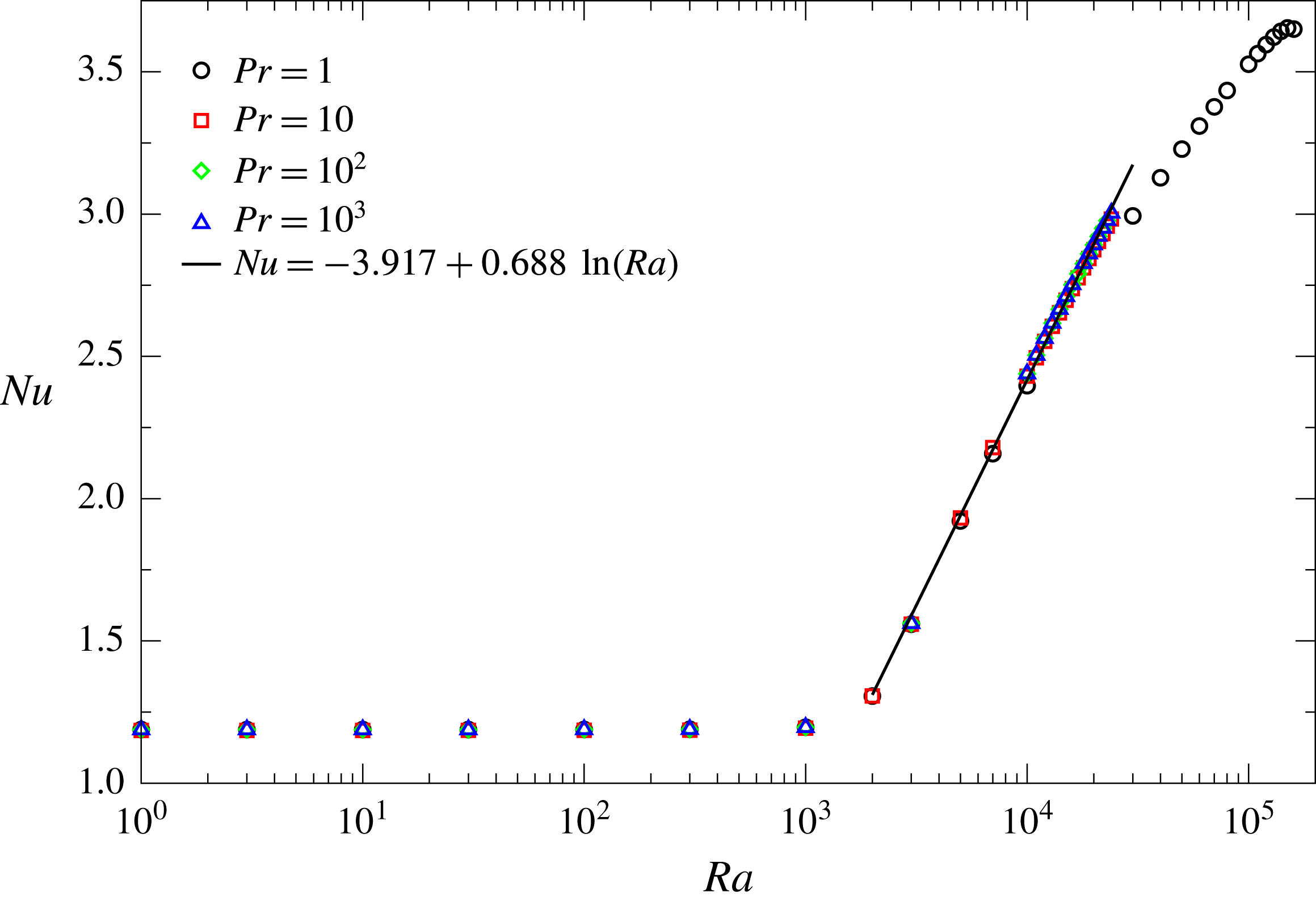
The Nusselt number defined by (3.4) has been plotted in figure 19 as a function of
 $Ra$
and for the four Prandtl numbers already mentioned. Clearly, two regimes are identified: for
 $Ra$
less than
 $10^{3}$
, the Nusselt number is constant, while for
 $Ra$
above
 $10^{3}$
, the Nusselt number increases with respect to
 $Ra$
. Notice that the Nusselt number in the conductive regime is larger due to the fact that without motion the temperature range is a little smaller when the electrode length is shorter than the cavity height, as can be seen in figure 18. For Prandtl numbers equal to
 $10$
to
 $10^{3}$
, the profiles are completely similar, meaning that the Prandtl number does not play a significant role. Moreover, a nonlinear fitting shows that the Nusselt number increases slowly with the Rayleigh number, since the dependence is logarithmic, as already pointed out by Sugilal et al. (Reference Sugilal, Wattal and Iyer2005). For a Prandtl number equal to one, the Nusselt number has been determined up to the limit over which the solution becomes unsteady. Even if the logarithmic behaviour is depicted as well for
 $Pr=1$
, the slope changes.
The Péclet and the Nusselt numbers provided in this subsection have been reported when a steady-state regime is obtained. Over a threshold in terms of Rayleigh number depending of the Prandtl number, the stationary state with the symmetrical structure is not reached. The following two subsections are devoted to the study of these transitions.
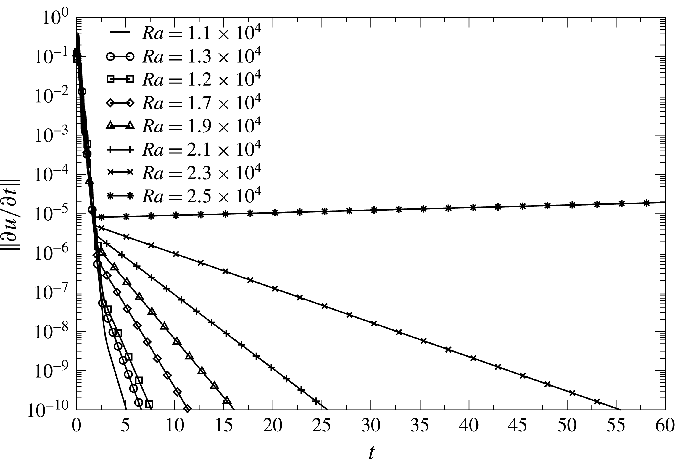
 $L^{2}$
-norm of the time derivative of the velocity in the cavity as a function of time for
 $L=2$
,
 $L_{e}=2/3$
and
 $Pr=10$
obtained with a mesh size equal to
 $h=2.5\times 10^{-2}$
and a time step equal to
 $2\times 10^{-3}$
.

4.3 Break-up of the symmetric solution for
$L_{e}=2/3$

To control the steady-state regime, the
 $L^{2}$
-norms of the time derivatives of the velocity and temperature fields with the backward differential formula at the second order are determined as a function of time. To improve the time resolution, the time step is set equal to
 $2\times 10^{-3}$
. The typical behaviour of the time derivative of the velocity field obtained for a particular Prandtl number equal to
 $10$
is depicted in figure 20. The Rayleigh number ranges between
 $1.1\times 10^{4}$
and
 $2.5\times 10^{4}$
. The computation is stopped either when the maximum of the time derivatives of velocity and temperature becomes less than
 $10^{-10}$
or when a predefined time is reached. At small Rayleigh numbers, convergence is quickly reached. Whatever the Rayleigh number, the time derivative of the velocity decreases exponentially with time due to the convergence following eigenmodes of the Navier–Stokes–Fourier equations. At short times, the fastest mode predominates, while at long times, when the largest modes have already converged, only the smallest mode remains, which corresponds to the second behaviour seen in figure 20. When the Rayleigh number increases, the absolute value of the smallest eigenvalue decreases, requiring a longer time to observe convergence. The fastest mode does not change significantly with the Rayleigh number, as shown in figure 20, where rates of convergence at short times are practically identical whatever
 $Ra$
. In contrast, the smallest mode depends strongly on the Rayleigh number. These results mean that the time derivative of the velocity during the second step behaves as follows:
 $$\begin{eqnarray}\displaystyle & \displaystyle \frac{\unicode[STIX]{x2202}\boldsymbol{u}(\boldsymbol{x},t)}{\unicode[STIX]{x2202}t}=\boldsymbol{A}(\boldsymbol{x})\text{e}^{\unicode[STIX]{x1D6FE}t}, & \displaystyle\end{eqnarray}$$
in which the eigenvalue
 $\unicode[STIX]{x1D6FE}$
characterizes the time convergence. As depicted in figure 20, below a critical value,
 $\unicode[STIX]{x1D6FE}$
is negative, and when the Rayleigh number becomes larger than a threshold which is close to
 $2.5\times 10^{4}$
for
 $Pr=10$
,
 $\unicode[STIX]{x1D6FE}$
becomes positive, meaning that the system evolves towards another state. The critical Rayleigh number of this first transition will be designated
 $Ra_{cr_{1}}$
.
When the Prandtl number is equal to one, the occurrence of the transition differs. First,
 $Ra_{cr_{1}}$
is much larger and requires more numerical accuracy. To determine the critical Rayleigh number we perform numerical simulations by increasing the spatial resolution with a mesh size equal to
 $1.76\times 10^{-2}$
, which increases the number of finite elements by a factor of two. The time step is once again taken equal to
 $2\times 10^{-3}$
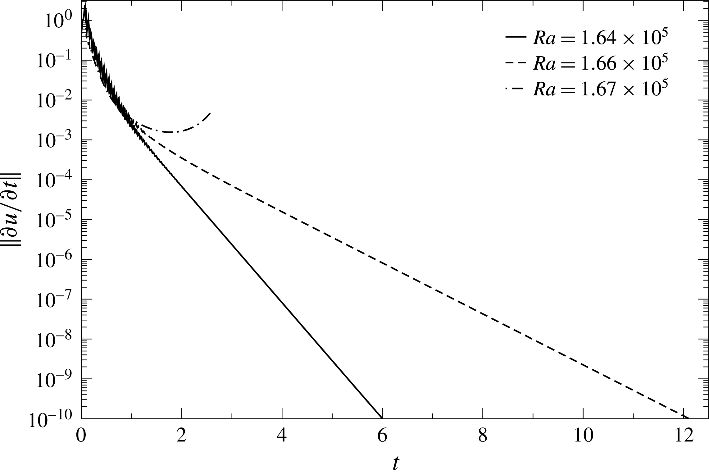
. Figure 21 depicts the
 $L^{2}$
-norm of the time derivative of the velocity as a function of time for three Rayleigh numbers taken close to the threshold. The critical Rayleigh number
 $Ra_{cr_{1}}$
is between
 $1.66\times 10^{5}$
and
 $1.67\times 10^{5}$
, meaning that when the Prandtl number is equal to one, we can take
 $Ra_{cr_{1}}=1.665\times 10^{5}$
with an uncertainty equal to 0.6 %. While for
 $Pr=10$
two steps are observed in the convergence towards the steady-state regime, only one step emerges for
 $Pr=1$
, underlining that the spectrum of eigenvalues is narrower for
 $Pr=1$
than for a larger Prandtl number.
 $L^{2}$
-norm of the time derivative of the velocity in the cavity as a function of time for
 $L=2$
,
 $L_{e}=2/3$
and
 $Pr=1$
obtained with a mesh size equal to
 $h=1.76\times 10^{-2}$
and a time step equal to
 $2\times 10^{-3}$
.

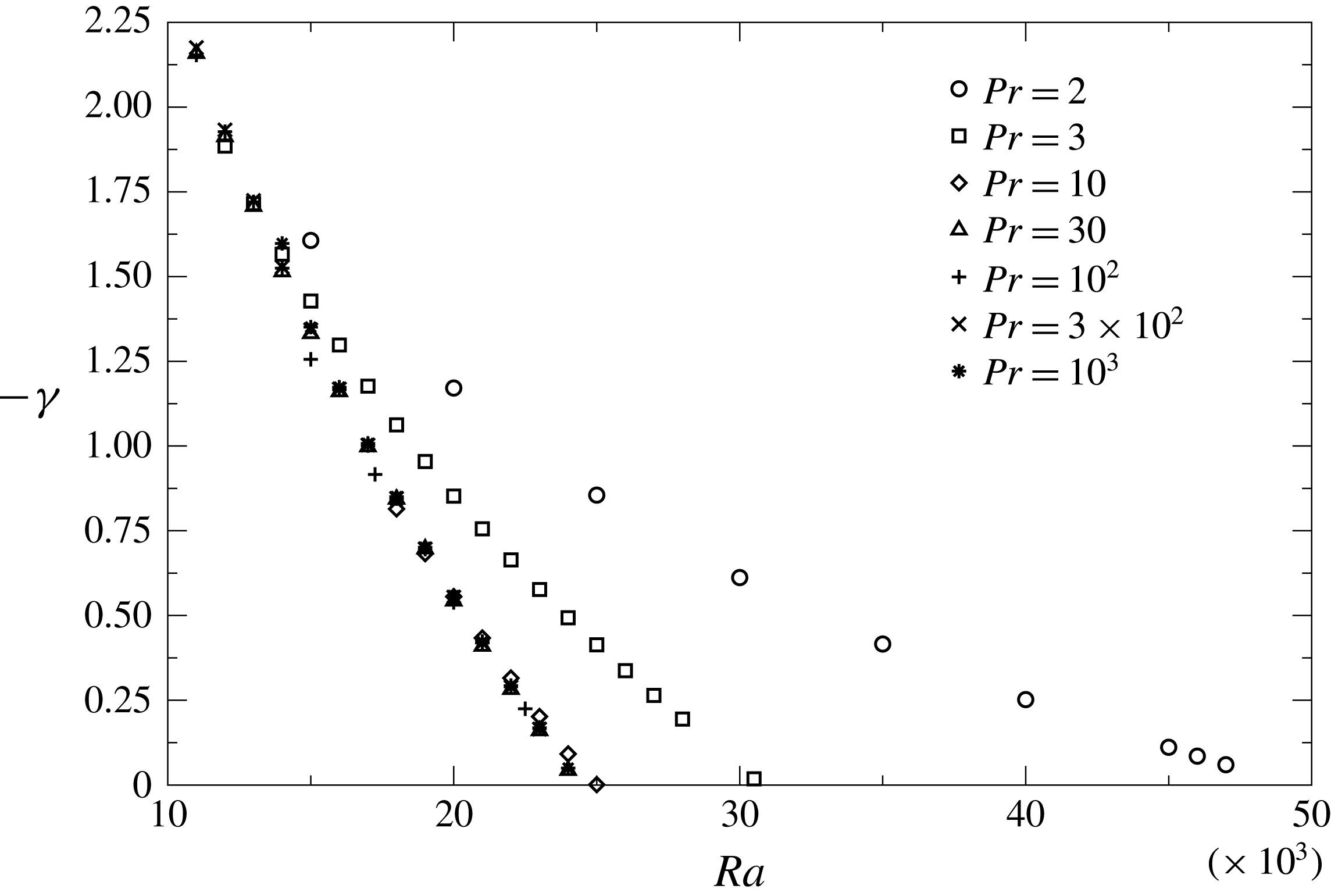
When the Prandtl number is larger than one, the critical Rayleigh number is determined by studying the behaviour of the eigenvalue
 $\unicode[STIX]{x1D6FE}$
given in (4.3). Due to a strong variation of the critical Rayleigh number when
 $Pr\in [1;10]$
,
 $\unicode[STIX]{x1D6FE}$
is investigated when the Prandtl number ranges between
 $2$
and
 $10^{3}$
. The eigenvalue
 $\unicode[STIX]{x1D6FE}$
has been determined by fitting the time derivative with a decaying exponential function of time. Figure 22 depicts
 $-\unicode[STIX]{x1D6FE}$
as a function of
 $Ra$
. For each Prandtl number, a quadratic function of
 $Ra$
is found. For the smallest Prandtl numbers, the Rayleigh number for which
 $\unicode[STIX]{x1D6FE}$
becomes positive is large, while when the Prandtl number becomes larger than
 $10$
, profiles of
 $-\unicode[STIX]{x1D6FE}$
merge towards a unique behaviour, meaning that the critical Rayleigh number does not change significantly.
Behaviour of
 $-\unicode[STIX]{x1D6FE}$
as a function of
 $Ra$
number for
 $Pr\in [2;10^{3}]$
.

To determine more accurately the value of
 $Ra_{cr_{1}}$
, each curve of
 $-\unicode[STIX]{x1D6FE}$
is fitted with a quadratic function of
 $Ra$
. The value of
 $Ra_{cr_{1}}$
is determined by finding the zero value of
 $-\unicode[STIX]{x1D6FE}$
. The solid line with circle symbols given later in figure 33 presents the first critical Rayleigh number
 $Ra_{cr_{1}}$
as a function of the Prandtl number, in which the critical Rayleigh number obtained for
 $Pr=1$
has been added.
 $Ra_{cr_{1}}$
decreases strongly when
 $Pr$
is in the range
 $[1;10]$
. As already mentioned, when
 $Pr=1$
, the critical Rayleigh number
 $Ra_{cr_{1}}$
is
 $1.665\times 10^{5}$
, while above
 $Pr=10$
,
 $Ra_{cr_{1}}$
is approximately equal to
 $2.5\times 10^{4}$
and does not change significantly for larger Prandtl numbers.
The thermal and kinematic structures shown in figure 15 for
 $Ra=10^{4}$
and
 $Pr=1$
for which two counter-rotating cells are observed do not stay stable above the critical Rayleigh number
 $Ra_{cr_{1}}$
. This bifurcation can be seen by looking at the behaviour of the
 $L^{2}$
-norm of
 $\boldsymbol{u}$
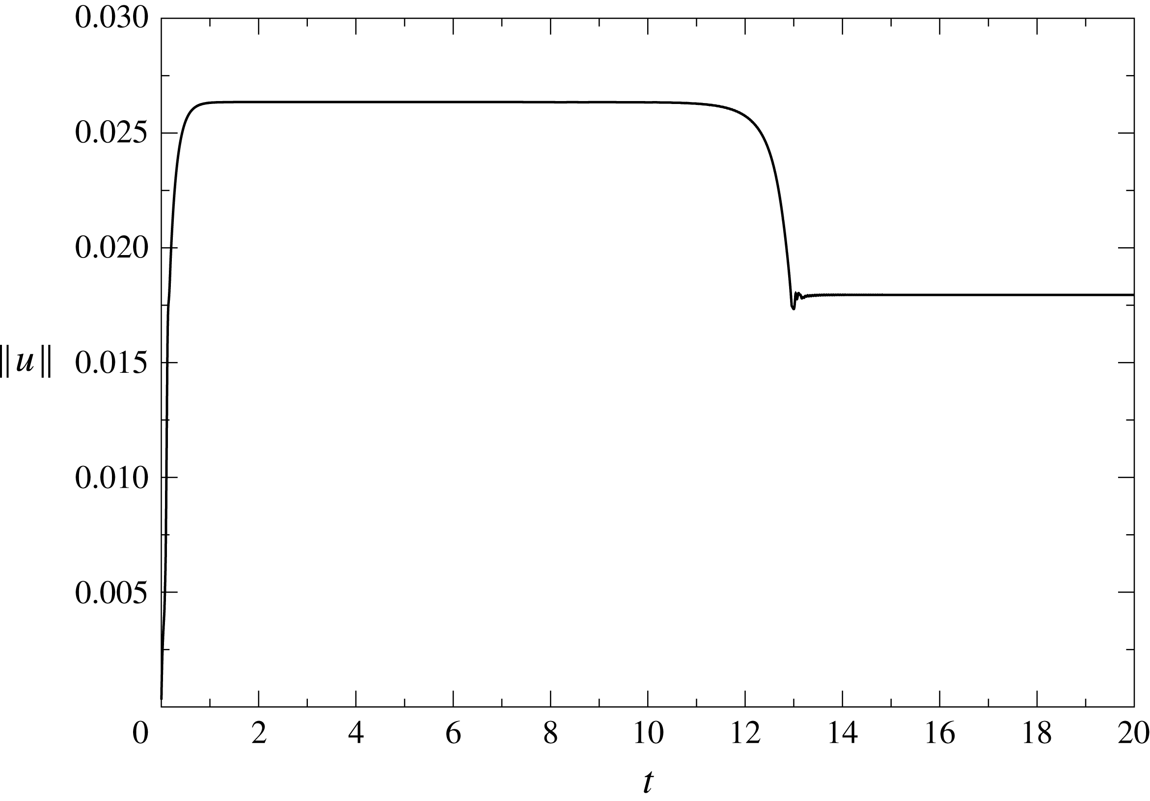
as a function of time. A typical curve is given in figure 23 when
 $Ra=3.5\times 10^{4}$
and
 $Pr=10^{2}$
, corresponding to a condition above the transition. After a fast increase, the velocity norm reaches a first plateau. When the time is larger than
 $13$
, the velocity decreases to reach a second plateau.
 $L^{2}$
-norm of
 $\boldsymbol{u}$
as a function of time obtained for
 $Pr=10^{2}$
and
 $Ra=3.5\times 10^{4}$
for
 $L=2$
, and
 $L_{e}=2/3$
.

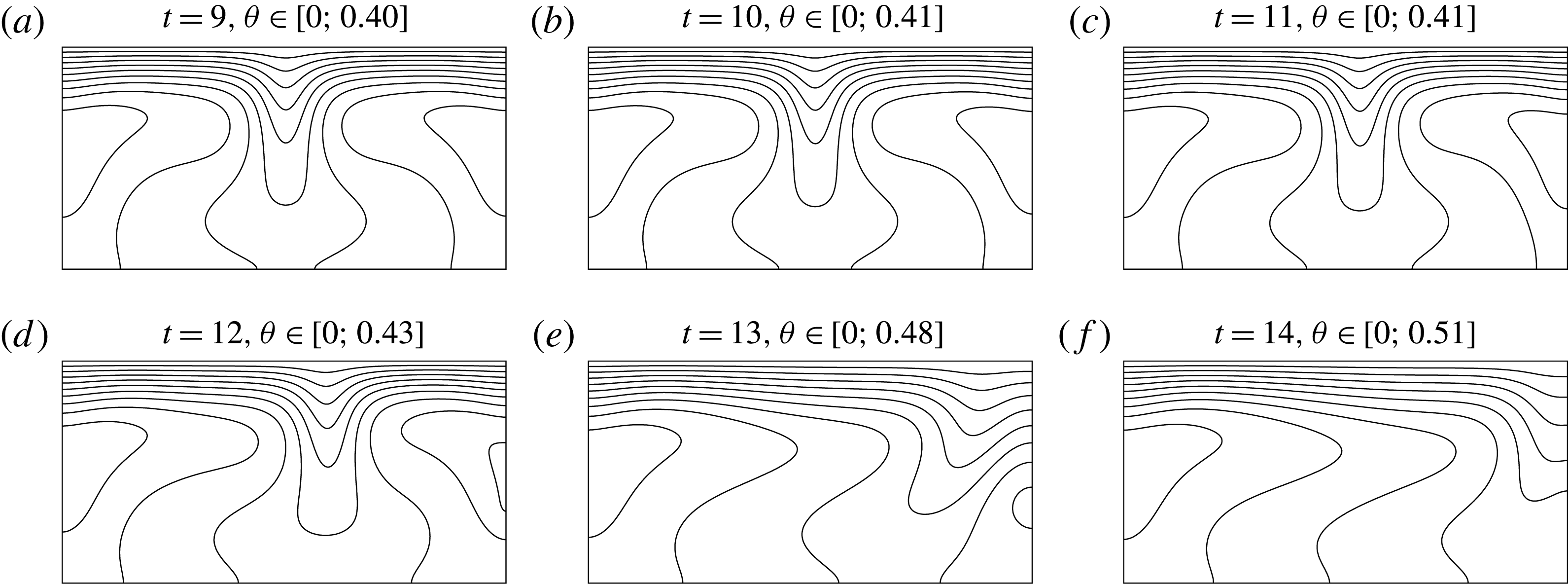
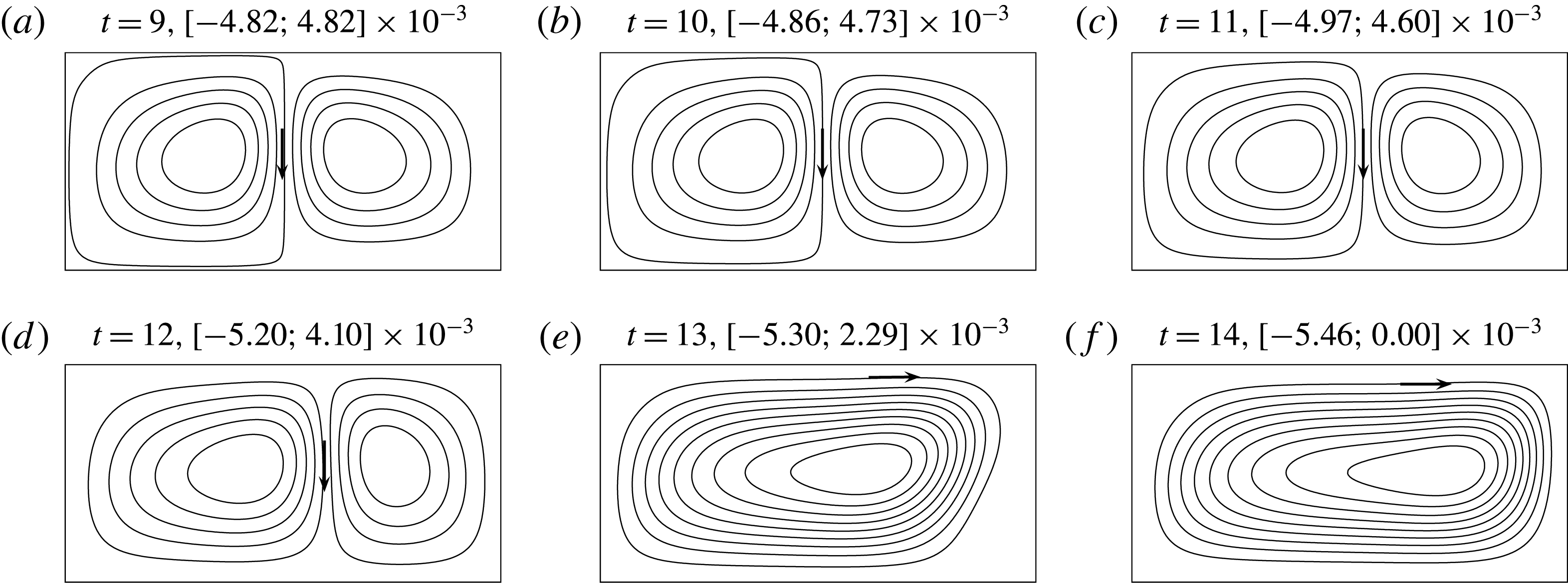
The modification of the flow structure can be seen by looking at the isovalues of the temperature field shown in figure 24 for which six snapshots have been reported. For the two first snapshots, the structures are symmetric, obtained when the velocity reaches the first plateau in figure 23. The observation of the stream function at the same times represented in figure 25 allows us to see the flow structure. For the two first snapshots, the flow structure is characterized by two counter-rotating cells. While at small times the temperature field is symmetric with respect to the middle vertical axis, the symmetry is broken when time becomes larger than
 $11$
, which is in the range where the
 $L^{2}$
-norm of the velocity plotted in figure 23 decreases. The stream function shows that the left-hand cell becomes more and more important relative to the right-hand cell (see figure 25). When the time is larger than
 $14$
, a steady-state asymmetric flow structure is observed with only one cell.
Snapshots of 10 equally spaced isolines of
 $\unicode[STIX]{x1D703}$
obtained for
 $Pr=10^{2}$
and
 $Ra=3.5\times 10^{4}$
when time is equal to (a)
 $t=9$
, (b)
 $t=10$
, (c)
 $t=11$
, (d)
 $t=12$
, (e)
 $t=13$
and (f)
 $t=14$
.

Snapshots of 10 equally spaced isolines of
 $\unicode[STIX]{x1D713}$
obtained for
 $Pr=10^{2}$
and
 $Ra=3.5\times 10^{4}$
when time is equal to (a)
 $t=9$
, (b)
 $t=10$
, (c)
 $t=11$
, (d)
 $t=12$
, (e)
 $t=13$
and (f)
 $t=14$
. For each subfigure, the range of
 $\unicode[STIX]{x1D713}$
has been reported in each subcaption.

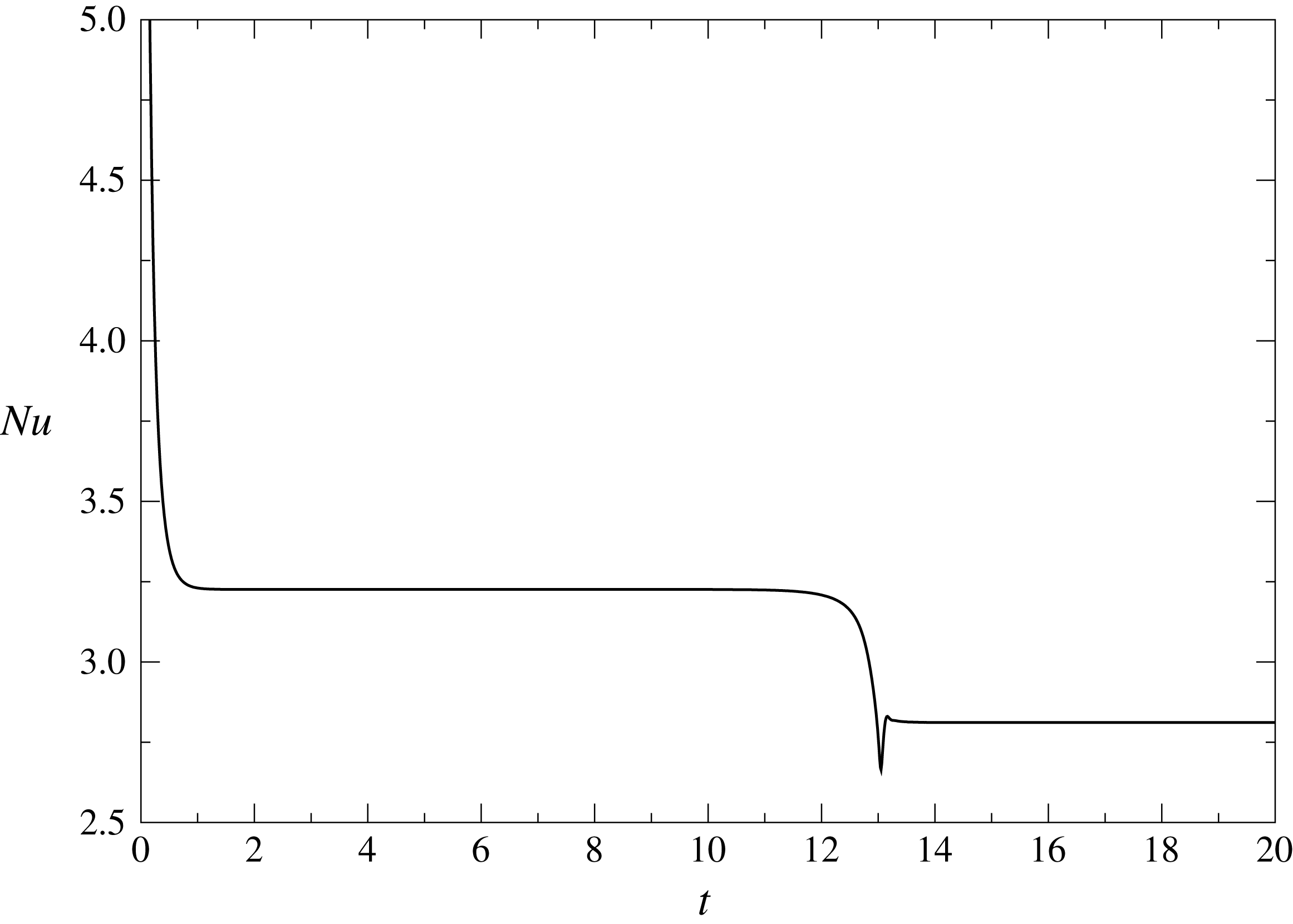
The transition from the two symmetric cells to one asymmetric cell also has an effect on the behaviour of the Nusselt number. In figure 26, the time behaviour of
 $Nu$
is plotted when the Rayleigh number is equal to
 $3.5\times 10^{4}$
and
 $Pr=10^{2}$
. As for the norm of the velocity field, two values of the Nusselt number arise. The first plateau is obtained when the flow structure is composed by the two symmetric cells. After a fast transition obtained when
 $t\sim 13$
, the Nusselt number decreases by 13 % to reach a second constant value when the second regime is fully established.
 $Nu$
as a function of time obtained for
 $Pr=10^{2}$
and
 $Ra=3.5\times 10^{4}$
for
 $L=2$
, and
 $L_{e}=2/3$
.

The asymmetric solution observed in subfigures 24(f) and 25(f) is characterized by a clockwise cell. This rotation is chosen artificially by the solver. Indeed, due to the left–right symmetry, a solution with an anticlockwise rotation cell is totally possible. From a previous converged solution, a numerical test with an initialized solution obtained by changing
 $x$
in
 $L-x$
proves that the anticlockwise cell structure is also a solution, meaning that we found two branches of solutions respecting the symmetry of the problem.
Once again, the transition when the Prandtl number is equal to one is different. A numerical simulation has been made at
 $Ra=1.68\times 10^{5}$
. Figure 27 depicts six snapshots of isovalues of
 $\unicode[STIX]{x1D703}$
. Starting from a symmetric structure relatively similar to the previous one observed at
 $Pr=100$
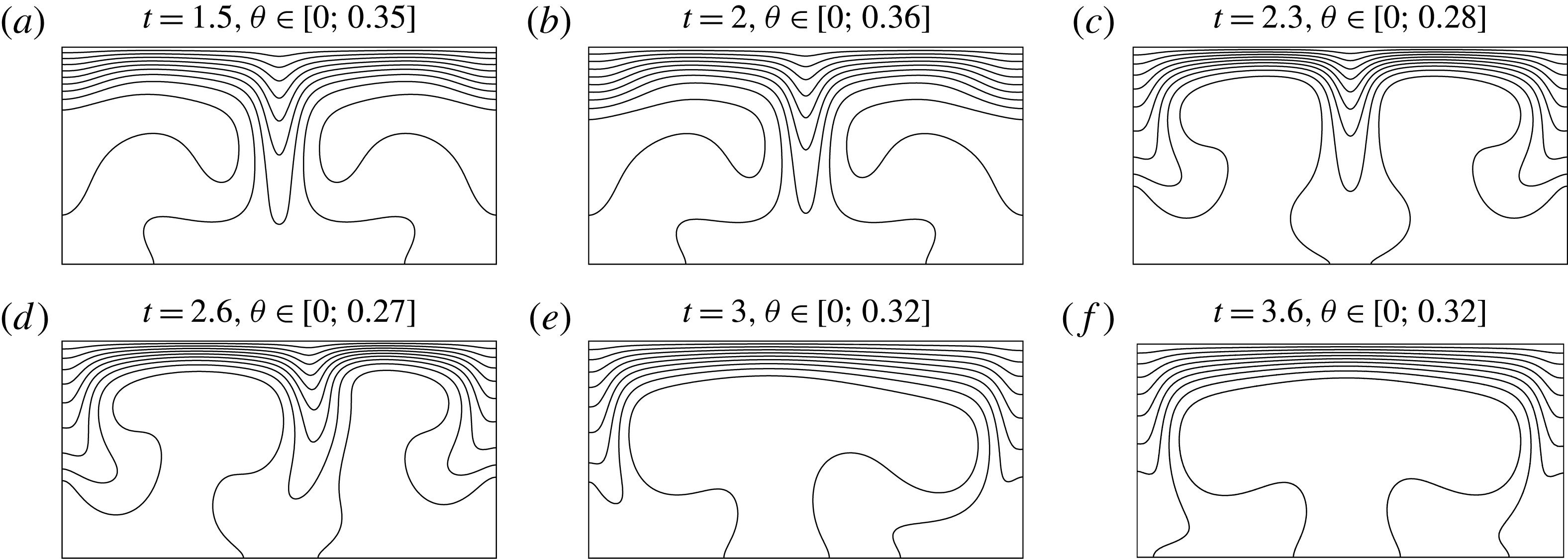
, the flow structure changes completely, as can be seen in figure 27(c). Two counter-rotating cells are present but with a change in rotation. Before the transition, the fluid moves up close to the vertical boundaries, while at the transition, the fluid moves down close to the vertical walls. After a period of transition, the flow is structured with two counter-rotating cells for which the fluid moves up in the middle of the cavity, leading to a creation of a plume. As seen in figure 27(f) obtained at
 $t=3.6$
, the structure is quite symmetric, which is not the case of the transition observed when the Prandtl number is larger than
 $3$
. The solution obtained for
 $Pr=1$
is similar to that reported by Sugilal et al. (Reference Sugilal, Wattal and Iyer2005).
Snapshots of 10 equally spaced isolines of
 $\unicode[STIX]{x1D703}$
obtained for
 $Pr=1$
and
 $Ra=1.68\times 10^{5}$
for (a)
 $t=1.5$
, (b)
 $t=2$
, (c)
 $t=2.3$
, (d)
 $t=2.6$
, (e)
 $t=3$
and (f)
 $t=3.6$
.

It is noteworthy that when the Prandtl number is less than
 $3$
, the flow structure becomes asymmetric over
 $Ra_{cr_{1}}$
as observed for larger
 $Pr$
. Moreover, numerical solutions performed for larger Rayleigh numbers converge towards a steady-state structure similar to the one observed at
 $Pr=1$
. For a Prandtl number larger than
 $3$
, this transition is not observed, but the solution becomes unsteady, as will be shown in the next subsection.
4.4 Hopf bifurcation for large
$Ra$
and
$Pr>10$


Solutions found for
 $(Ra=3.5\times 10^{4},Pr=10^{2})$
and
 $(Ra=1.68\times 10^{5},Pr=1)$
stay in a steady-state regime, since after the transition, the time convergence is numerically found. By increasing the Rayleigh number when
 $Pr>3$
, a second instability is established for which the solution becomes periodic in time. Using a simple dichotomy method, the onset of the second instability is determined. This second instability is characterized by a critical Rayleigh number
 $Ra_{cr_{2}}$
. Figure 33, given later, depicts the behaviour of
 $Ra_{cr_{2}}$
as a function of
 $Pr$
(solid line with square symbols).
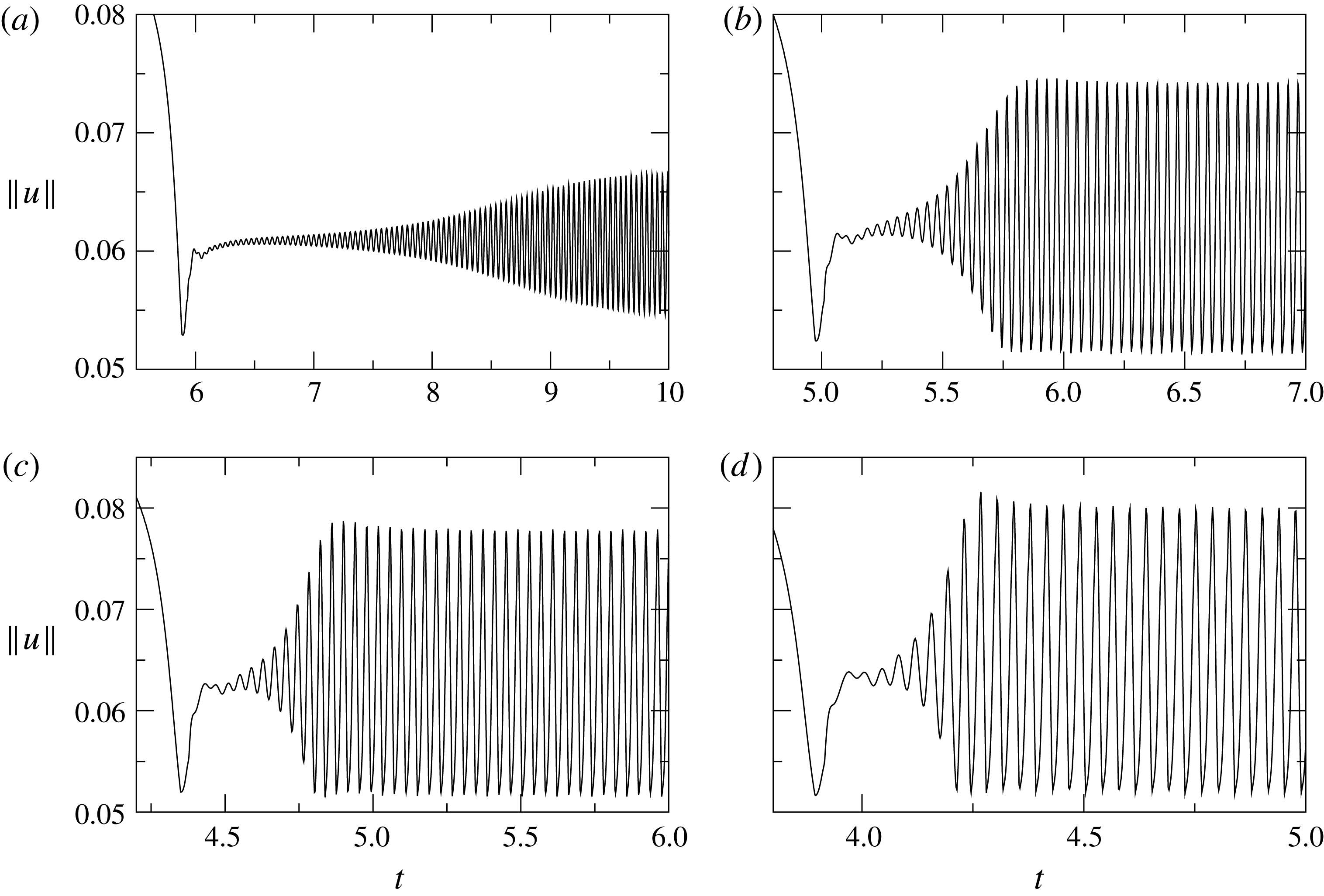
To see the occurrence of the periodic solution, figure 28 presents the behaviour of the
 $L^{2}$
-norm of the velocity for four Rayleigh numbers when the Prandtl number is equal to
 $10$
. As already seen in figure 23, the norm of the velocity rapidly reaches a plateau corresponding to the symmetric configuration followed by a decrease of the flow intensity. Figure 28 depicts the behaviour after the first transition. The establishment of the periodic solution depends on the gap between the Rayleigh number used for a particular computation and
 $Ra_{cr_{2}}$
. The transition occurs earlier when the Rayleigh number increases. The periodic regime begins with an increase in the amplitude of oscillations and its duration becomes shorter as
 $Ra$
increases. Amplitudes of velocity oscillations grow with the Rayleigh number.
 $\Vert \boldsymbol{u}\Vert$
as a function of
 $t$
for
 $Pr=10$
and (a)
 $Ra=4.5\times 10^{4}$
, (b)
 $Ra=5\times 10^{4}$
, (c)
 $Ra=5.5\times 10^{4}$
and (d)
 $Ra=6\times 10^{4}$
.

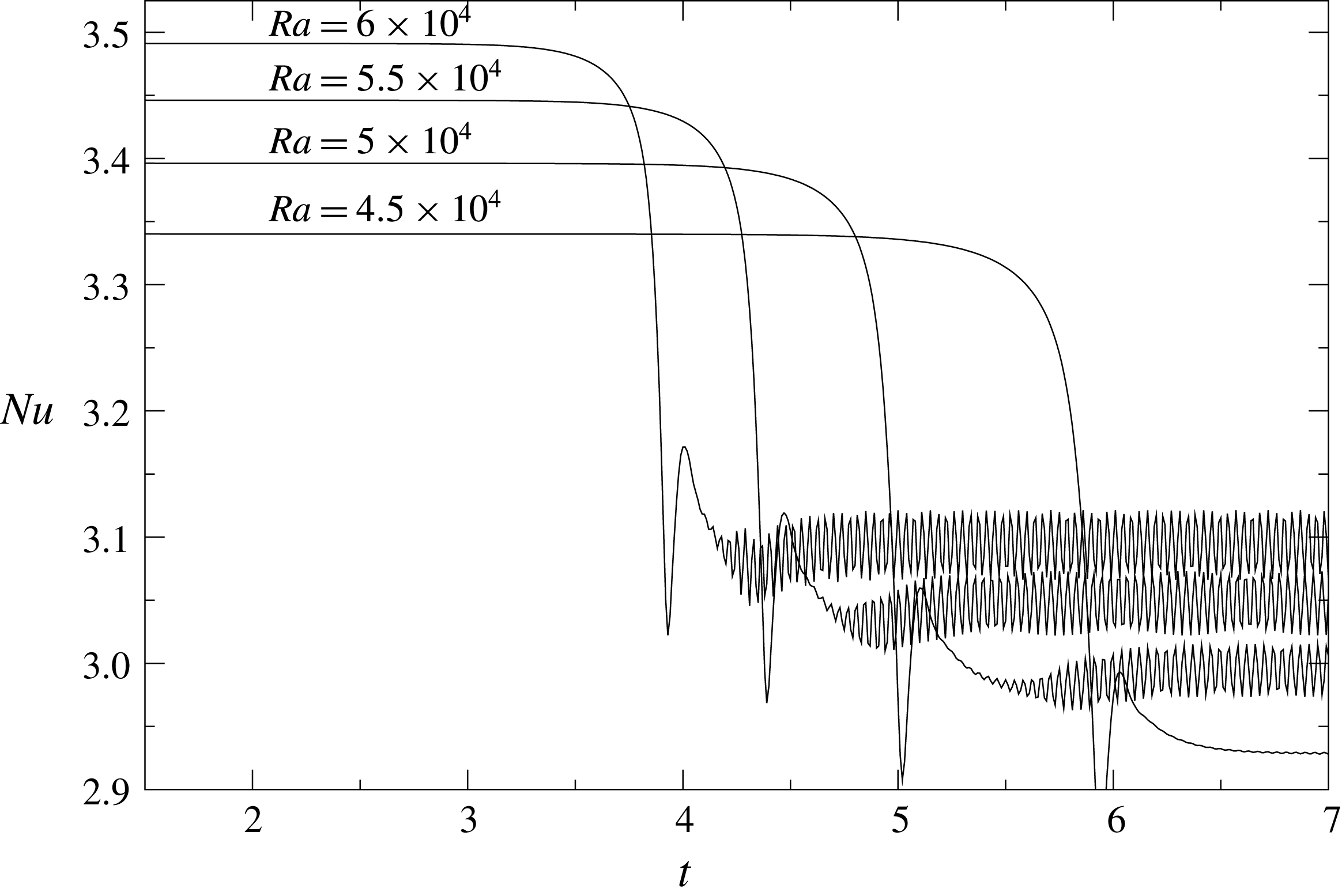
In order to see the effect of the second transition on the thermal structure, the Nusselt number is plotted as a function of time in figure 29 when the Prandtl number is equal to
 $10$
and for four Rayleigh numbers equal to
 $4.5\times 10^{4}$
,
 $5\times 10^{4}$
,
 $5.5\times 10^{4}$
and
 $6\times 10^{4}$
. As already mentioned above, the transition to the second instability occurs later when the Rayleigh number is slightly larger than the critical Rayleigh number. The periodic solution does not lead to a strong effect on the Nusselt number. While the oscillation on the velocity is clearly observed when
 $Ra=4.5\times 10^{4}$
, the Nusselt number stays more and less stable above the second transition. The amplitude of
 $Nu$
increases for larger Rayleigh numbers, but the increase is very weak. We previously observed that the Nusselt number evolves slowly with the Rayleigh number when
 $Ra$
is smaller than
 $Ra_{cr_{1}}$
. Therefore, it is expected to see a weak effect on heat transfer.
 $Nu$
as a function of
 $t$
for
 $Pr=10$
and for
 $Ra=4.5\times 10^{4}$
,
 $5\times 10^{4}$
,
 $5.5\times 10^{4}$
and
 $6\times 10^{4}$
.

In order to show typical results, we provide a movie available athttps://doi.org/10.1017/jfm.2018.168 recording the temperature field determined when the
 $Pr=10^{2}$
and
 $Ra=4\times 10^{4}$
. From the initial condition, for which the temperature is set equal to zero, the temperature field rapidly reaches the first regime, corresponding to the symmetric condition. After a certain time, the flow moves to the asymmetric structure. Finally, the oscillations start to grow before reaching the periodic regime. The oscillations are mainly observed close to the right vertical wall in the enclosure. Nevertheless, as already pointed out in the previous subsection, in which a steady-state one cell structure has been obtained, the periodic solution with an anticlockwise cell can be obtained numerically. This means that once again two branches of solutions are possible.
Fourier spectra of the norm of
 $\Vert \boldsymbol{u}\Vert$
for (a)
 $Pr=10$
and (b)
 $10^{2}$
.

Additional calculations have been made for Prandtl numbers equal to
 $10$
,
 $10^{2}$
and
 $10^{3}$
and for various Rayleigh numbers above
 $Ra_{cr_{2}}$
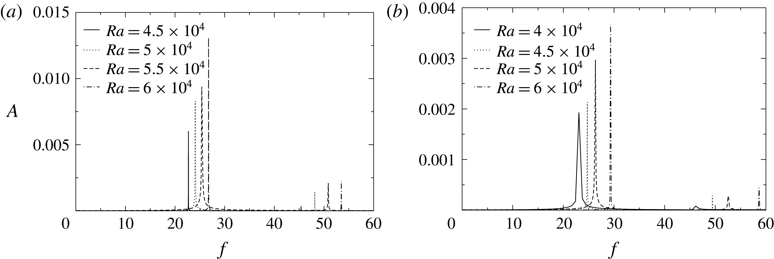
. In order to obtain more information about the nature of the second instability, a Fourier analysis has been performed in the time range for which the flow is fully periodic. Figure 30 depicts the Fourier spectra obtained for two Prandtl numbers and four Rayleigh numbers. The amplitude and the frequency are respectively designated by
 $A$
and
 $f$
. Signals are very close to a sinusoidal behaviour with a fundamental frequency and an amplitude corresponding to the velocity oscillation seen in figure 28. Secondary peaks are observed at a frequency equal to a second harmonic of the signal, but with a much smaller amplitude.
From the asymmetric solution established when the Rayleigh number is above
 $Ra_{cr_{1}}$
, the flow solution converges towards a limit cycle when
 $Ra>Ra_{cr_{2}}$
. The periodic solutions observed here look like a supercritical Hopf bifurcation which can be characterized by the amplitude and the frequency of oscillations (Manneville Reference Manneville2004). Using the Fourier analysis, the amplitude and the frequency of the fundamental harmonic can be determined. As already pointed out in § 4.2, the flow motion is very well described in terms of the Péclet number whatever the Prandtl number. In order to have an amplitude similar to the Péclet number, the fundamental amplitude is multiplied by
 $\sqrt{RaPr}$
. According to Manneville (Reference Manneville2004, pages 128–129), the oscillation amplitude is a function of the reduced control parameter
 $r$
given for this second instability by
 $$\begin{eqnarray}\displaystyle & \displaystyle r=\frac{Ra-Ra_{cr_{2}}}{Ra_{cr_{2}}}. & \displaystyle\end{eqnarray}$$
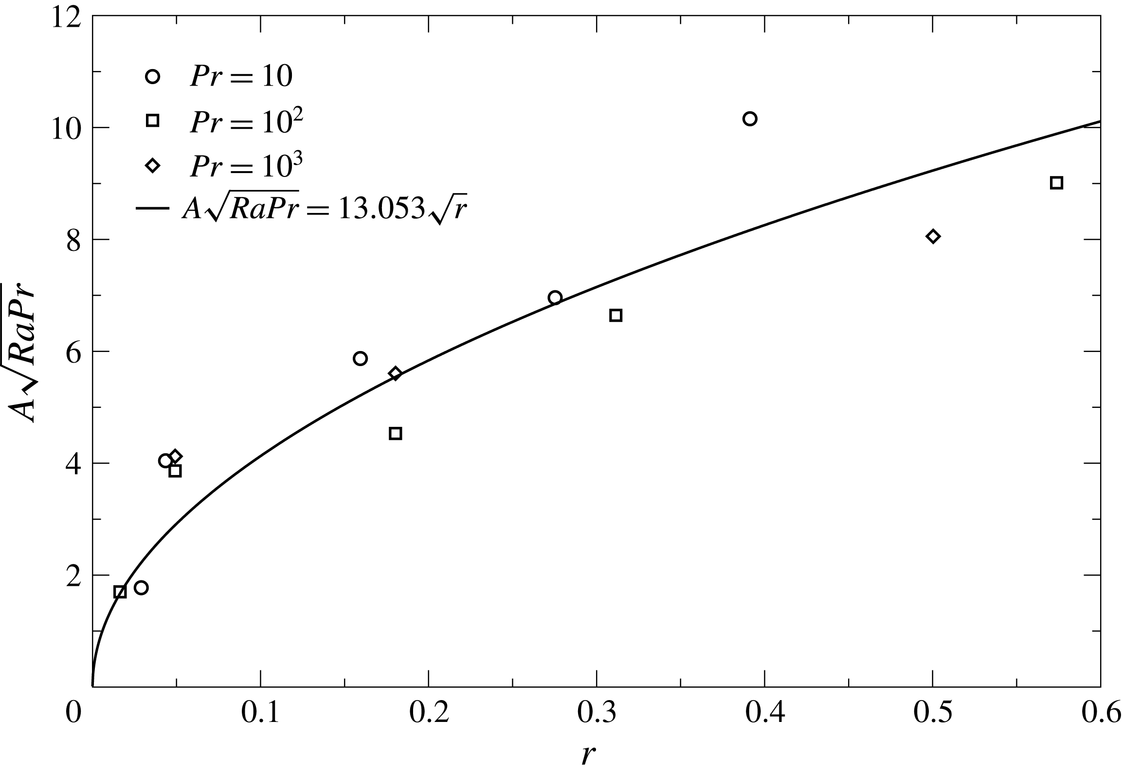
Figure 31 presents the fundamental amplitude multiplied by
 $\sqrt{RaPr}$
as a function of
 $r$
for
 $Pr=10$
,
 $10^{2}$
and
 $10^{3}$
. Even if numerical results are little scattered, meaning that the limits of our numerical resolutions are close, a clear trend is observed. A nonlinear regression shows that the amplitude grows as the square root of
 $r$
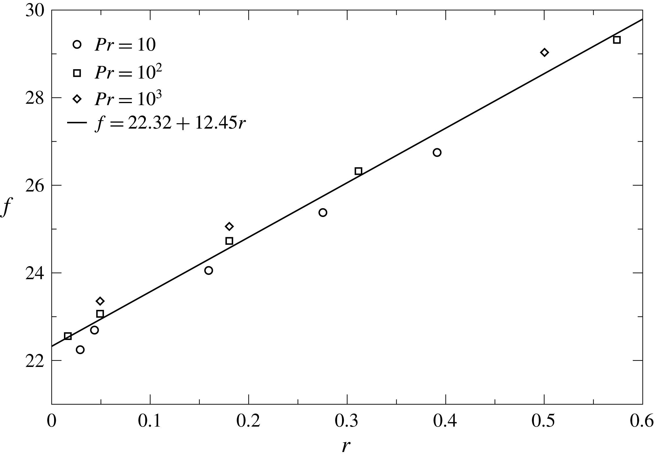
, as expected in the Hopf bifurcation. Moreover, the fundamental frequency
 $f$
plotted as a function of
 $r$
provided in figure 32 shows that
 $f$
is a linear function of the reduced control parameter.
Fundamental amplitude
 $A\sqrt{RaPr}$
as a function of the reduced control parameter
 $r$
for three Prandtl numbers.

Fundamental frequency
 $f$
as a function of the reduced control parameter
 $r$
for three Prandtl numbers.

It is noteworthy that the periodic solution presents a master result whatever the Prandtl number, which has important consequences for industrial applications. Moreover, when the Prandtl number is larger than
 $10^{2}$
, the critical Rayleigh numbers
 $Ra_{cr_{1}}$
and
 $Ra_{cr_{2}}$
do not depend on
 $Pr$
. Consequently, only the Rayleigh number remains as a control parameter of the flow.
4.5 Stability diagram
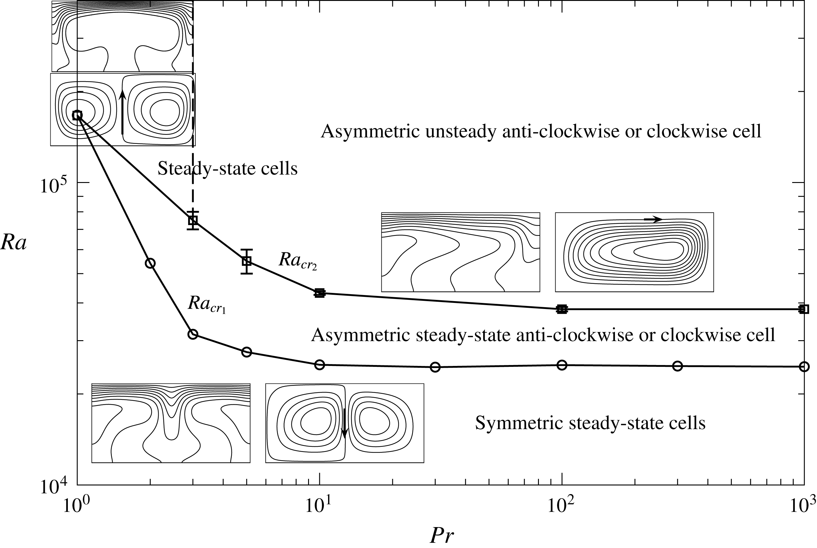
A summary of the four main structures obtained for the specific electrode length
 $L_{e}=2/3$
is provided in figure 33. Below the curve giving
 $Ra_{cr_{1}}$
, the flow is composed of a unique symmetric structure with a left clockwise cell and a right anticlockwise cell. The fluid goes from the top to the bottom in the middle of the enclosure. In this regime, the Péclet number is a linear function of
 $Ra$
when
 $Ra<10^{3}$
and a square root function of
 $Ra$
when
 $Ra>10^{3}$
. Above the first critical Rayleigh number, an asymmetric structure is observed for which anticlockwise or clockwise cells are obtained. The characteristic of the transition between symmetric/asymmetric solutions is hard to establish with our time integration method. A stability study would be needed to explain why the symmetric solution does not stay stable. Nevertheless, the base solution is hard to extract to perform a stability analysis. Physically, the mechanism of the destabilization would be due to the instability of the central jet. Indeed, if the jet shifts a little horizontally then a disequilibrium in pressure occurs, pushing the jet towards the side where the jet is shifted.
Stability diagram
 $(Pr,Ra_{cr_{1,2}})$
describing the three main structures obtained numerically when
 $L_{e}=2/3$
. The first transition is delimited by
 $Ra_{cr_{1}}$
given as a solid line with circle symbols. The second transition is given by
 $Ra_{cr_{2}}$
as a solid line with square symbols.

Below a Prandtl number equal to
 $3$
and above a second critical Rayleigh number, a third flow structure is observed, characterized by a left anticlockwise cell and a right clockwise cell, leading to vertical flow in the middle of the enclosure. Finally, when the Prandtl number is larger than
 $3$
and for
 $Ra>Ra_{cr_{2}}$
, an unsteady asymmetric structure arises. Due to left–right symmetry of the problem, two branches of solutions with anti- and clockwise cells exist.
4.6 Consequences for electric glass melting
Results obtained may have important consequences for the glass melting process. First, the occurrence of asymmetric structures can lead to a disequilibrium of the electric circuit and of the fusion of raw materials. When the flow structure shifts from a symmetric structure to an asymmetric situation, for which hot spots are observed close to electrodes, the raw materials can disappear and the thermal insulation is strongly affected. Moreover, electrodes can be eroded strongly. Unsteady solutions can also be a source of process instabilities difficult to control for glass makers.
From the linear regression given in figure 32, the dimensionless frequency is larger than
 $22.32$
. In order to have an idea concerning the value of this frequency in SI units, the dimensionless frequency has to be multiplied by
 $\unicode[STIX]{x1D705}/H^{2}$
. Since the typical height in glass melting industry is approximately one metre, only the value of the thermal diffusivity is required. As already mentioned in the introduction and in § 2, radiation is the main mode of thermal transfer. Using a simple Rosseland approximation, the thermal conductivity is given by (Viskanta & Anderson Reference Viskanta and Anderson1975)
 $$\begin{eqnarray}\displaystyle & \displaystyle \unicode[STIX]{x1D706}=\frac{16n^{2}\unicode[STIX]{x1D70E}_{\text{SB}}T^{3}}{3\unicode[STIX]{x1D6FD}_{\text{R}}}, & \displaystyle\end{eqnarray}$$
with
 $n$
is the refractive index (typically equal to
 $1.5$
for glass former liquids),
 $\unicode[STIX]{x1D70E}_{\text{SB}}$
is the Stefan–Boltzmann constant, equal to
 $5.67\times 10^{-8}~\text{W}~\text{m}^{-2}~\text{K}^{-4}$
,
 $T$
is the absolute temperature and
 $\unicode[STIX]{x1D6FD}_{\text{R}}$
is the Rosseland absorption coefficient given in
 $\text{m}^{-1}$
. For the typical glass composition used to make wool insulation, the Rosseland absorption coefficient is equal to
 $200~\text{m}^{-1}$
. Since the thermal diffusivity is given by
 $\unicode[STIX]{x1D706}/(\unicode[STIX]{x1D70C}C_{p})$
and if the temperature is taken equal to
 $1300~^{\circ }\text{C}$
,
 $\unicode[STIX]{x1D705}$
is approximately
 $3\times 10^{-6}~\text{m}^{2}~\text{s}^{-1}$
. Using the dimensionless frequency equal to
 $22.23$
, we found that oscillations occur at
 $3\times 10^{-4}~\text{Hz}$
, corresponding to a time period of approximately one hour. For a dark glass, the Rosseland absorption coefficient is much larger and is typically equal to
 $1000~\text{m}^{-1}$
, giving a smaller oscillation frequency of approximately
 $6\times 10^{-5}~\text{Hz}$
(time period close to
 $5~\text{h}$
).
5 Conclusion
This work has been devoted to natural convection in a Joule-heated cavity. A non-uniform volumetric heat source is produced by an electric field applied with two vertical electrodes localized on the vertical walls of the enclosure. The coupled Navier–Stokes, heat transfer and electric potential equations are solved using a discontinuous Galerkin finite element technique. The solver is tested in a situation for which the heat source is uniform in volume, leading to a threshold in convection similar to that of classical Rayleigh–Bénard convection. The critical Rayleigh number is determined. The bifurcation is similar to a transcritical one for which two solutions are possible. The heat transfer is characterized by computing the average temperature profile over the horizontal coordinate.
After this preliminary test validating the numerical solver, we shorten the electrodes from the bottom. In such a case, the threshold disappears and the flow exists as soon as the Rayleigh number is larger than zero. By studying the full range of the electrode length, an optimal length has been obtained when the Rayleigh number is less than 1702.
Numerical simulations have been made for a large range of Prandtl numbers, between 1 and
 $10^{3}$
, and a large range of Rayleigh numbers, up to
 $10^{5}$
, limited to only one electrode length set equal to
 $2/3$
of the cavity height. This case presents a large possibility of solutions, starting from a symmetric two-cell steady state with two rotation directions, an asymmetric cell steady state, and finally asymmetric cell time-periodic solutions. In the first kind of solution, the intensity of convection can be characterized in terms of the Péclet number. Two regimes arise: one obtained when the Rayleigh number is smaller than
 $10^{3}$
, exhibiting a linear behaviour of the Péclet number versus the Rayleigh number; the second regime is characterized by a square root dependency of the Péclet number as a function of Rayleigh number.
On increasing the Rayleigh number, the flow does not remain in the symmetric structure. Using the behaviour of the convergence towards the steady-state regime, we establish the behaviour of the critical Rayleigh number as a function of the Prandtl number of this first transition. At small Prandtl number, the dependency on the critical Rayleigh number is very important. However, when the Prandtl number is larger than
 $10$
, the critical Rayleigh number does not change significantly and is equal to
 $2.5\times 10^{4}$
.
This second solution becomes periodic in time above a second critical Rayleigh number which is less sensitive to the Prandtl number. Performing numerical simulations for Rayleigh numbers above the second critical Rayleigh number allows us to quantify the amplitudes and frequencies of the observed oscillations. We prove that the nature of the second instability is a supercritical Hopf bifurcation. A stability diagram has been established. Even though one electrode length has been investigated, it is expected that with another electrode length the critical Rayleigh numbers will change. However, the various solutions established in this work should be the same.
In terms of industrial processes, the occurrence of a periodic flow can be a source of difficulties in controlling industrial plants. In the glass industry, the typical Rayleigh number is always larger than the critical value found in the present study. Moreover, we observe that the flow structure can change dramatically, which can be deleterious for working conditions. Conversely, these instabilities could be an opportunity to control the heat and mass transfer, since we establish a simple relation between oscillating solutions and the Rayleigh number. The purpose here should be to improve the homogenization process, which is very important in applications because the forming process is mainly controlled by the thermal and chemical homogeneities of the glass former liquid at the exit of the furnace.
Even if careful attention has been paid to obtain good numerical accuracy, our solutions have a limit in terms of space and time resolutions. Due to the large range of possible solutions and the dependence on up to three parameters, a continuation method would be more appropriate to explore the stability of this kind of problem. Moreover, our study focuses only on two-dimensional configurations and only one length of electrode has been investigated. To examine whether such instabilities are also present in more realistic situations, we plan to extend this work to three-dimensional numerical simulations in the near future.
Acknowledgements
The authors would like to thank M. J. Toplis (IRAP, Toulouse) for his help in the preparation of the article. We are also indebted to anonymous referees for perspicacious comments and suggestions in the structure of this article which strongly improved its quality.
Supplementary movie
A supplementary movie is available at https://doi.org/10.1017/jfm.2018.168.
Appendix A. Scaling analysis
In the problem statement, the set of conservative equations are normalized by characteristic quantities justified by a scaling analysis provided in this appendix.
A.1 Temperature scale
The scale of temperature range can be established by studying the solution without motion. Indeed, when the electric potential is applied on the entire vertical boundary, i.e.
 $L_{e}=H$
,
 $\unicode[STIX]{x1D6F7}$
is given by the following linear relation:
 $$\begin{eqnarray}\displaystyle & \displaystyle \unicode[STIX]{x1D6F7}=\unicode[STIX]{x1D6F7}_{0}\left(1-\frac{x}{L}\right). & \displaystyle\end{eqnarray}$$
With this electric field, the temperature without motion can also be found easily. Its solution is
 $$\begin{eqnarray}\displaystyle & \displaystyle T=T_{0}+\frac{\unicode[STIX]{x1D70E}\unicode[STIX]{x1D6F7}_{0}^{2}H^{2}}{2\unicode[STIX]{x1D706}L^{2}}\left(1-\frac{y^{2}}{H^{2}}\right). & \displaystyle\end{eqnarray}$$
With this solution, the difference of temperature can be defined as follows:
 $$\begin{eqnarray}\displaystyle & \displaystyle \unicode[STIX]{x0394}T=\frac{\unicode[STIX]{x1D70E}\unicode[STIX]{x1D6F7}_{0}^{2}H^{2}}{2\unicode[STIX]{x1D706}L^{2}}, & \displaystyle\end{eqnarray}$$
which arises from the balance between thermal conduction and Joule dissipation.
When the electrode length is smaller than
 $H$
, the electric field is no longer a linear function of
 $x$
and the accurate solution must be determined numerically. As it pointed out in § 4,
 $\unicode[STIX]{x1D6F7}$
exhibits strong variations close to electrodes. However, outside the vertical walls, the electric potential is quasilinear, meaning that the Joule dissipation source is approximately uniform. The range of temperature does not change significantly, and the previous estimation can be applied. With such a scaling, the temperature can be written in the following dimensionless form:
 $$\begin{eqnarray}\displaystyle & \displaystyle \unicode[STIX]{x1D703}=\frac{T-T_{0}}{\unicode[STIX]{x0394}T}. & \displaystyle\end{eqnarray}$$
Note that when
 $L_{e}=H$
, the thermal field is independent of
 $x$
and is thermally unstable.
A.2 Velocity scale
The space coordinates are normalized with the height of the enclosure,
 $H$
. Before studying the scaling of the velocity, the dimensionless forms of the potential,
 $\unicode[STIX]{x1D6F7}$
, and
 $\boldsymbol{J}$
have to be defined. It is obvious that
 $\unicode[STIX]{x1D6F7}$
is reduced by
 $\unicode[STIX]{x1D6F7}_{0}$
. Following Ohm’s law,
 $$\begin{eqnarray}\displaystyle & \displaystyle \boldsymbol{J}=-\unicode[STIX]{x1D70E}\unicode[STIX]{x1D735}\unicode[STIX]{x1D6F7}, & \displaystyle\end{eqnarray}$$
where
 $\boldsymbol{J}$
is normalized by
 $\unicode[STIX]{x1D70E}\unicode[STIX]{x1D6F7}_{0}/H$
.
The velocity field is normalized by a scale
 $U$
, the time by
 $\unicode[STIX]{x1D70F}$
and the pressure by
 $\unicode[STIX]{x1D6FF}P$
. In the following, all dimensionless variables are written with the same symbols already introduced so that no misunderstanding is possible.
It is noteworthy that due to the fact that the pressure gradient must be kept in the momentum equation in order to satisfy the continuity equation,
 $\unicode[STIX]{x1D6FF}P$
is on the order of
 $\unicode[STIX]{x1D70C}g\unicode[STIX]{x1D6FD}\unicode[STIX]{x0394}TH$
. Reporting these scalings in the momentum equation gives the general form of the momentum equation
 $$\begin{eqnarray}\displaystyle & \displaystyle Re\left(St\frac{\unicode[STIX]{x2202}\boldsymbol{u}}{\unicode[STIX]{x2202}t}+\boldsymbol{u}\boldsymbol{\cdot }\unicode[STIX]{x1D735}\boldsymbol{u}\right)=-\unicode[STIX]{x1D735}p+\unicode[STIX]{x1D6FB}^{2}\boldsymbol{u}+\frac{Gr}{Re}\unicode[STIX]{x1D703}\boldsymbol{e}_{y}, & \displaystyle\end{eqnarray}$$
for which the dimensionless numbers are the following:
 $$\begin{eqnarray}\displaystyle & \displaystyle Re=\frac{UH}{\unicode[STIX]{x1D708}}:\text{Reynolds number,} & \displaystyle\end{eqnarray}$$
 $$\begin{eqnarray}\displaystyle & \displaystyle St=\frac{H}{\unicode[STIX]{x1D70F}U}:\text{Strouhal number,} & \displaystyle\end{eqnarray}$$
 $$\begin{eqnarray}\displaystyle & \displaystyle Gr=\frac{g\unicode[STIX]{x1D6FD}\unicode[STIX]{x0394}TH^{3}}{\unicode[STIX]{x1D708}^{2}}:\text{Grashof number,} & \displaystyle\end{eqnarray}$$
and
 $\unicode[STIX]{x1D708}=\unicode[STIX]{x1D702}/\unicode[STIX]{x1D70C}$
is the kinematic viscosity. Recall that the Reynolds number is the ratio of the inertial to viscous forces. The Strouhal number, which will be examined in the next subsection, compares the relevant time scale of the dynamics to the advection time over the height of the cavity. The Grashof number is a relevant number when buoyancy forces are involved in the dynamics. It can be seen as the ratio of the momentum diffusion time to advection time due to buoyancy forces. Recall that the Grashof number can be given as a function of two other classical numbers as follows:
 $$\begin{eqnarray}\displaystyle & \displaystyle Gr=\frac{Ra}{Pr}, & \displaystyle\end{eqnarray}$$
with
 $Ra$
the Rayleigh number and
 $Pr$
the Prandtl number defined by (2.12) and (2.13), respectively.
Two main scenarios appear as a function of the Reynolds number. First, if
 $Re$
is assumed small, a balance force is achieved between the viscosity and buoyancy effects, leading to the following scaling of the Reynolds number:
 $$\begin{eqnarray}\displaystyle & \displaystyle Re=Gr. & \displaystyle\end{eqnarray}$$
In such a situation, the velocity scale
 $U$
is proportional to
 $\unicode[STIX]{x1D6FD}\unicode[STIX]{x0394}TgH^{2}/\unicode[STIX]{x1D708}$
. Conversely, if the inertia is important, the balance is achieved between inertial and buoyancy terms. Consequently, the Reynolds number behaves as
 $$\begin{eqnarray}\displaystyle & \displaystyle Re=\sqrt{Gr}, & \displaystyle\end{eqnarray}$$
leading to the order of magnitude of
 $U$
being equal to
 $\sqrt{\unicode[STIX]{x1D6FD}\unicode[STIX]{x0394}TgH}$
.
A.3 Time scale
The time scale is given by the amplitude of the Strouhal number. Since two types of transfer occur in this problem, i.e. momentum and heat, the dynamics is controlled by the slowest phenomena. In order to establish the order of magnitude of the Strouhal number, the thermal equation can be rewritten in a dimensionless form using the previous scaling as follows:
 $$\begin{eqnarray}\displaystyle & \displaystyle St\frac{\unicode[STIX]{x2202}\unicode[STIX]{x1D703}}{\unicode[STIX]{x2202}t}+\unicode[STIX]{x1D735}\unicode[STIX]{x1D703}\boldsymbol{\cdot }\boldsymbol{u}=\frac{1}{PrRe}\left[\unicode[STIX]{x1D6FB}^{2}\unicode[STIX]{x1D703}+2L^{2}\left(\unicode[STIX]{x1D735}\unicode[STIX]{x1D6F7}\right)^{2}\right]. & \displaystyle\end{eqnarray}$$
Recall here the length
 $L$
is the dimensionless length.
By using the dimensionless momentum (A 6) and assuming that the Reynolds number is larger than one, the Strouhal number can be scaled by
 $$\begin{eqnarray}\displaystyle & \displaystyle St=\min \left(\frac{1}{Re},\frac{1}{PrRe}\right), & \displaystyle\end{eqnarray}$$
for which two limit cases arise as a function of the Prandtl number. Since in the framework of this study the Prandtl number is considered larger than one, the Strouhal number is given by
 $$\begin{eqnarray}\displaystyle & \displaystyle St=\frac{1}{PrRe}, & \displaystyle\end{eqnarray}$$
meaning that the time scale is controlled by the thermal diffusion, for which the typical time scale is
 $\unicode[STIX]{x1D70F}=H^{2}/\unicode[STIX]{x1D705}$
.
To solve numerically the coupled Navier–Stokes–Fourier equations, the velocity scale is taken in the limit of large Reynolds number, meaning that this dimensionless number is the square root of the Grashof number. This choice has been done because when the Grashof number is large the buoyancy term becomes important. By taking
 $Re=\sqrt{Gr}$
, a better balance of the various terms in the momentum equation is obtained since the convective and buoyancy terms are of the same order of magnitude.
Following these developments, the momentum and thermal partial differential equations can be written as follows:
 $$\begin{eqnarray}\displaystyle & \displaystyle \frac{1}{Pr}\frac{\unicode[STIX]{x2202}\boldsymbol{u}}{\unicode[STIX]{x2202}t}+\sqrt{\frac{Ra}{Pr}}\boldsymbol{u}\boldsymbol{\cdot }\unicode[STIX]{x1D735}\boldsymbol{u}=-\unicode[STIX]{x1D735}p+\unicode[STIX]{x1D6FB}^{2}\boldsymbol{u}+\sqrt{\frac{Ra}{Pr}}\unicode[STIX]{x1D703}\boldsymbol{e}_{y}, & \displaystyle\end{eqnarray}$$
 $$\begin{eqnarray}\displaystyle & \displaystyle \frac{\unicode[STIX]{x2202}\unicode[STIX]{x1D703}}{\unicode[STIX]{x2202}t}+\sqrt{PrRa}\unicode[STIX]{x1D735}\unicode[STIX]{x1D703}\boldsymbol{\cdot }\boldsymbol{u}=\unicode[STIX]{x1D6FB}^{2}\unicode[STIX]{x1D703}+2L^{2}\left(\unicode[STIX]{x1D735}\unicode[STIX]{x1D6F7}\right)^{2}, & \displaystyle\end{eqnarray}$$
meaning that the momentum equation is quasisteady when
 $Pr\gg 1$
.