I. INTRODUCTION
Supercapacitors are regarded as a new type of energy storage devices with high power density and long lifespan. Supercapacitors are classified into electric double-layer capacitor (EDLC) and pseudocapacitor based on the different mechanism of charge storage. Different electrode materials have been developed such as various carbons, conducting polymers, and transition metal oxides or nitrides.Reference Simon and Gogotsi1–Reference Xie, Du and Xia5 EDLC achieves energy store by forming a double layer of electrolyte ions on the surface of conductive porous carbon materials such as activated carbon, carbon nanotubes, and carbon aerogels.Reference Shukla, Banerjee, Ravikumar and Jalajakshi6,Reference Xie and Zhan7 However, low energy density limits their energy-offering application. On the other hand, pseudocapacitor achieves high charge storage through reversible faradaic redox reaction between metal oxides or conducting polymers and reactive electrolytes.Reference Zheng8–Reference Xie and Du10
Manganese dioxide (MnO2) is considered as a good candidate of supercapacitor electrode material because of its electrochemical behavior, low cost, and environmental compatibility.Reference Yan, Fan, Wei, Qian, Zhang and Wei11–Reference Xia, Xie, Du and Wang13 MnO2 has a high theoretical capacitance of 1370 F g−1. Nevertheless, MnO2 does not usually deliver ideal specific capacitance because of its poor electrical conductivity and electrochemical dissolution during cycling process.Reference Wei, Cui, Chen and Ivey14,Reference Ma, Nam, Yoon, Yang, Ahn, Oh and Kim15 To overcome these weaknesses, carbonaceous materials with high electrical conductivity has been widely chosen as buffer matrices of MnO2 to improve the conductivity and cycling stability.Reference Ma, Nam, Yoon, Yang, Ahn, Oh and Kim15,Reference Kim, Kouda, Yoshimoto and Morita16 Graphene is emerging as one of the most appealing carbon material because of its unique properties such as superior electrical conductivity, excellent mechanical flexibility, and high thermal and chemical stability.Reference Xie and Zhan7,Reference Kretinin, Cao, Tu, Yu, Jalil, Novoselov, Haigh, Gholinia, Mishchenko, Lozada, Georgiou, Woods, Withers, Blake, Eda, Wirsig, Hucho, Watanabe, Taniguchi, Geim and Gorbachev17 To improve the electrical conductivity and specific surface area of MnO2 electrode material, a variety of Manganese dioxide/reduced graphene oxide (MnO2/RGO) composites has been prepared through various methods such as hydrothermal, refluxing, and chemical precipitation.Reference Jiang, Cui and Ma18–Reference Kim, Hwang and Kim20 These MnO2/RGO composites show the improved capacitance performance compared to pure MnO2.Reference Kim, Hwang and Kim20–Reference Rusi and Majid22 However, the specific capacitances still need to be improved to meet the practical applications.Reference Chan, Rusi and Majid21 The capacitance of the electrode materials is usually dependent on their specific surface area and electroactivity. The larger surface area and good ionic transport can lead to a higher current density and facilitate the fast transport of electrolyte ions.Reference Luo, Cheng and Xia23 The highly ordered micro/nanostrutured materials with high accessible surface area are very suitable for various electrochemical applications.Reference Xie24–Reference Xie and Wang28 Especially, hollow structure could improve the surface-to-volume ratio and ion transportation for MnO2 electrode materials.Reference Sawangphruk and Limtrakul29,Reference Gu, Cai, He, Kang, Lei and Liu30 The electroactivity is related to the electrical conductivity and interfacial reactivity of electrode materials.Reference Kumar and Lee31 Usually, the graphite could be used as the carbon layer to improve the electrical conductivity of MnO2. Furthermore, the graphene produced by graphite delamination has superior electrical conductivity, excellent mechanical flexibility, and high thermal and chemical stability, presenting more effective carbon covering layer of MnO2. Polystyrene (PS) is a versatile polymer with the spherical feature to act as a useful template to prepare hollow structure materials. MnO2/carbon hollow sphere has been developed via directly growing MnO2 nanosheets on hollow carbon shell through redox reaction between KMnO4 and carbon, showing a specific capacitance of 105.5 F g−1 at 0.5 A g−1.Reference Li, Li, Gai, Ding, He, Zhang and Yang32
In this study, the MnO2/RGO double-shelled hollow microsphere was synthesized through graphene oxide (GO) adsorption on the surface of PS microsphere, chemical reduction of GO, in situ deposition of MnO2, and chemical etching of PS. The well-designed RGO/MnO2 hollow microsphere could contribute to the improved electrical conductivity and electrolyte ion diffusion, leading to a superior capacitance performance in the application of supercapacitor electrode material.
II. EXPERIMENTAL
A. Material preparation
Figure 1 shows the schematic illustrating the fabrication process of MnO2/RGO doubled-shelled hollow microsphere. PS microsphere was used as a self-sacrificing template. Firstly, GO/PS core–shell microsphere was formed by coating GO layer on the surface of PS microsphere. GO involves vinyl functional group derivatives due to the presence of oxygen-functional hydrophilic groups such as hydroxyl, carbonyl, and carboxyl, which facilitate to form strong π–π stacking interaction between PS and GO.Reference Fang, Wang, Lu, Yang and Nutt33 RGO/PS core–shell microsphere was formed through chemical reduction treatment of GO/PS using hydrazine hydrate. Then, MnO2/RGO/PS core-shell–shell microsphere was synthesized through in situ chemical reduction of KMnO4 using benzyl alcohol which was initially anchored to RGO/PS.Reference Wu, Chen and Yan34 Finally, MnO2/RGO double-shelled hollow microsphere was obtained by chemically etching PS microsphere from MnO2/RGO/PS using tetrahydrofuran (THF) solvent.
Schematic illustrating the fabrication process of MnO2/RGO doubled-shelled hollow microsphere.

The detailed synthesis process of MnO2/RGO double-shelled hollow microsphere was shown as follows. GO was synthesized by the modified Hummers' method. 50 mL concentrated sulfuric acid was added into 1.0 g graphite powder under ice bath condition. 6 g potassium permanganate (KMnO4) was added slowly into the mixture and kept on stirring for 48 h at room temperature. 90 mL DI water, 20 mL hydrogen peroxide, and 280 mL warm water were sequentially added into above brown slurry. The obtained yellow suspension was centrifuged and washed using 6 wt% HCl solution and water. The suspension was dried in an oven at 70 °C to obtain GO powder. PS monodispersive microsphere was synthesized by dispersion polymerization process.Reference Jin, Higashihara, Jin, Yoon, Rho, Ahn, Kim, Hirao and Ree35 Styrene monomer and poly(vinyl pyrrolidone) stabilizer with a weight ratio of 9:1 were dispersed in ethanol and water mixture solution with a volume ratio of 68:72. K2S2O8 as an initiator was then added into this mixture and kept on stirring for 20 min under a nitrogen atmosphere. The polymerization reaction of styrene monomer was conducted at 70 °C for 12 h to form monodispersive PS microsphere. The PS microsphere was dispersed in the GO suspension with a weight ratio of GO/PS of 1:10. The obtained suspension was ultrasonically treated for 30 min, and kept on stirring for 3 h at 100 °C to remove residual water. The RGO/PS core–shell microsphere was obtained through chemical reduction treatment of GO/PS using hydrazine hydrate. MnO2/RGO/PS core-shell-shell microsphere was synthesized by in situ chemical reduction of KMnO4 using benzyl alcohol which was initially anchored to RGO/PS in an aqueous suspension.Reference Fang, Wang, Lu, Yang and Nutt33 In brief, 60 μL benzyl alcohol and then 300 mg RGO/PS was added into 20 mL DI water under mild stirring condition.Reference Wu, Chen and Yan34 The hydrophobic benzyl alcohol was adsorbed on the surface of RGO/PS through ultrasonic treatment for 30 min. 50 mg KMnO4 was added into the above solution and kept on mild stirring for 10 h. Herein, the MnO2/RGO could be prepared through a reduction-induced in situ self-assemblyReference Wu, Chen and Yan34 of MnO2 nanoparticles depositing on the surface of RGO/PS microsphere in an aqueous suspension. In neutral or weak alkaline reaction medium, MnO4− could be reduced into MnO2, which involved the following redox reaction.

In this process, the benzyl alcohol acts as a linker between RGO and MnO4−, and also serves as a sacrificial reductant to reduce the aqueous MnO4− ion into insoluble MnO2 on the surface of RGO/PS microsphere.Reference Wu, Chen and Yan34 Considering the chemical reduction function of benzyl alcohol to convert GO into RGO, the benzyl alcohol could well prevent the chemical oxidation of RGO.Reference Russo, Donato, Donato, Leonardi, Baek, Conte, Neri and Pinna36 MnO2/RGO double-shelled hollow microsphere was obtained by etching PS microsphere from MnO2/RGO/PS using THF solvent for 24 h. The mass ratio of MnO2 and RGO was determined to be 62.4:37.6 in MnO2/RGO double-shelled hollow microsphere.
The supercapacitor electrodes were prepared by loading electroactive materials on nickel foam (NF) as a current collector. MnO2/RGO double-shelled hollow microsphere was dispersed in alcohol and then deposited on NF to form MnO2/RGO/NF electrode through dip-coating process. The active surface area of NF was 2.0 cm2. The total loading mass of MnO2/RGO was 5.0 mg. For a comparison, MnO2/RGO mixture composite was also prepared by a simple physical mixture using MnO2 and RGO with a controlled mass ratio of 62:38, which is close to MnO2/RGO hollow microsphere. RGO hollow microsphere was also prepared by etching PS from RGO/PS core–shell microsphere. All these electrochemical measurements were conducted in 0.5 M Na2SO4 solution using a three-electrode system.
B. Characterization and measurement
The morphology and microstructure of MnO2/RGO doubled-shelled hollow microsphere were investigated using a field emission scanning electron microscope (FESEM, Zeiss Ultra-Plus, Carl Zeiss AG Co., Oberkochen, Germany) and transmission electron microscopy (TEM, JEM-2100, JEOL Ltd., Tokyo, Japan). X-ray diffraction (XRD) patterns were recorded using a x-ray diffractometer (Rigaku, Dmax-2500, Rigaku Corporation, Tokyo, Japan) operating at Cu Kα = 1.54056 Å, 40 kV and 40 A. Electrochemical impedance spectroscopy (EIS) measurements were conducted in a frequency range of 0.01–100000 Hz and a potential amplitude of ±5 mV using the electrochemical workstation (IM6e ZAHNER Elektrik, Kronach, Germany). The electrochemical capacitance was investigated through the galvanostatic charge–discharge (GCD) measurement using an electrochemical testing system (PAR VersaSTAT3 electrochemical analyzer, Princeton Applied Research, Oakridge, Tennessee). The cycle voltammetry (CV) measurement was conducted using an electrochemical workstation (CHI 760D, Shanghai Chenhua Instrument Co., Shanghai, China). The three-electrode system included the working electrode of MnO2/RGO/NF, the counter electrode of a platinum plate, Hg/Hg2Cl2 reference electrode and 0.5 mol L−1 Na2SO4 electrolyte solution. A potential window was controlled from 0 to 0.8 V. The term “hollow microsphere” as used in the following figures has the same meaning as the term “double-shelled hollow microsphere”.
III. RESULTS AND DISCUSSION
A. Microstructure characterization
The microstructure of RGO/PS core–shell microsphere, RGO hollow microsphere, MnO2/RGO/PS core-shell-shell microsphere and MnO2/RGO double-shelled hollow microsphere was characterized by SEM and TEM. Figure 2(A–C) shows SEM and TEM images of RGO/PS with different magnification. PS microsphere kept monodispersive characteristic and a uniform particle-size distribution with a diameter of 570–580 nm. RGO with a layer thickness of 70–80 nm could be well coated on the surface of PS microsphere. As-formed RGO/PS core–shell microsphere displayed a close-packing microstructure. Figure 2(D) shows TEM image of RGO formed by removing PS from RGO/PS core–shell microsphere. RGO revealed multiple-layer film structure with a transparent characteristic. RGO sheet was composed of the superposing RGO thin-layers through layer-by-layer self-assembly process. The residual RGO sheet kept a hollow microsphere structure. Figure 2(E–H) shows SEM and TEM images of MnO2/RGO/PS with different deposition degree of MnO2/RGO on PS. MnO2 could well coat on the surface of RGO/PS to form a villous layer microstructure. As-formed MnO2/RGO composite shell layer was surrounded on the outer surface of PS microsphere. The corresponding layer thickness of MnO2/RGO kept in the range of 210–270 nm and obviously increased along with more loading of MnO2. Figure 2(I–L) shows SEM and TEM images of MnO2/RGO with different magnification. MnO2 layer and RGO layer could well interconnect to construct a composite shell. TEM image reveals that the residual MnO2/RGO sheet still kept a hollow microsphere structure with a pore size of 560–580 nm. The uniformly distributed pore size was completely consistent with the diameter of PS microsphere. Moreover, the MnO2 nanoparticles tended to form a dense deposition layer, presenting a dendrite microstructure. The transparent RGO multiple-layer had accordingly converted into opaque MnO2/RGO double-shelled layer.
SEM and TEM images of (a, b, and c) RGO/PS core–shell microsphere; (d) RGO hollow microsphere; (e, f, g, and h) MnO2/RGO/PS core-shell-shell microsphere; and (i, j, k, and l) MnO2/RGO double-shelled hollow microsphere.
Figure 3 shows XRD patterns of RGO hollow microsphere and MnO2/RGO double-shelled hollow microsphere. A broad diffraction peaks at 2θ = 26.6° and 43.5° was ascribed to (002) and (100) lattice planes of RGO (see curve a).Reference Lee, Bak, Lee, Jaye, Fischer, Kim, Yang, Nam and Kim37 Comparatively, the corresponding characteristic peaks kept a much weaker intensity for MnO2/RGO due to the shield effect of MnO2 nanoparticles covering on RGO. Other characteristic diffraction peaks were observed at 2θ = 12.3°, 18.7°, 36.8°, and 65.7°, which were ascribed to (002), (101), (006), and (119) lattice planes of birnessite-type MnO2 by referring to the PDF#18-0802 (see curve b).Reference Zhu and He38 The broad peaks were related to a low crystallinity originated from the random packing of MnO2. It should be noted that the increased crystallization degree can improve the stability of electrode material. But high crystallinity became not beneficial to the charge transportation, resulting in the lowed capacitive performance for MnO2.Reference Zhu and He38 Therefore, MnO2/RGO double-shelled hollow microsphere with low crystallinity was expected to perform a better electrical conductivity and higher energy storage to act as an electrode material of supercapacitor.
XRD patterns of (a) RGO hollow microsphere and (b) MnO2/RGO double-shelled hollow microsphere and the standard diffraction peaks of RGO and MnO2.
B. Electrochemical measurement
The CV, GCD, and EIS analysis were used to evaluate the electrochemical properties of MnO2/RGO double-shelled hollow microsphere. Figure 4(A–C) shows CV curves of RGO hollow microsphere, MnO2/RGO mixture composite and MnO2/RGO double-shelled hollow microsphere electrode materials in 0.5 M Na2SO4 electrolyte solution at a scan rate from 2 to 200 mV·s−1. The CV curve of RGO shows the nearly rectangular-like shape, indicating the ideal capacitive behavior of RGO [see Fig. 4(A)]. The CV curves of MnO2/RGO mixture composite and MnO2/RGO double-shelled hollow microsphere also showed the similar quasirectangular shape at a low scan rate. However, the current response of MnO2/RGO hollow microsphere was much higher than that of MnO2/RGO mixture composite [see Figs. 4(B) and 4(C)], which was ascribed to the unique microporous structure. This result can be attributed to fast electrosorption of Na+ cation and the subsequent quick reversible faradaic process proceeding of MnO2 from MnO2/RGO hollow microsphere.Reference Li, Li, Gai, Ding, He, Zhang and Yang32Figure 4(D) shows the estimated specific capacitance of RGO hollow microsphere, MnO2/RGO mixture composite and MnO2/RGO double-shelled hollow microsphere in dependence on scan rate. MnO2/RGO hollow microsphere exhibited higher capacitance performance than others at the same scan rate. The corresponding capacitance loss of RGO hollow microsphere, MnO2/RGO mixture composite and MnO2/RGO hollow microsphere was determined to be 57.6, 81.2, and 69.1% when the scan rate increased from 2 to 100 mV·s−1. It means that the pseudocapacitor of MnO2/RGO showed much higher capacitance but less rate capability than electrochemical double-layer capacitor of RGO. The overall capacitance of MnO2/RGO was mostly ascribed to the Mn(IV)/Mn(III) reversible transition of MnO2/MnOONa in cyclic charge/discharge process. The good interfacial contact between MnO2 and RGO as well as their unique double-shelled microstructure contributed to high capacitance for MnO2/RGO double-shelled hollow microsphere.
(A, B, and C) CV curves and (D) corresponding specific capacitance of RGO hollow microsphere, MnO2/RGO mixture composite and MnO2/RGO double-shelled hollow microsphere testing in 0.5 M Na2SO4 electrolyte solution at a scan rate of 2, 5, 20, 50, 100, and 200 mV s−1.
Figure 5(A–C) shows GCD curves of RGO hollow microsphere, MnO2/RGO mixture composite and MnO2/RGO double-shelled hollow microsphere at different current densities in 0.5 M NaSO4 electrolyte solution. Obviously, all GCD curves were close to a symmetrical triangle shape, indicating a good reversible charge/discharge process. Figure 5(D) shows the capacitance plots of above different electrode materials. The specific capacitance of RGO hollow microsphere, MnO2/RGO mixture composite and MnO2/RGO double-shelled hollow microsphere was 110.8, 172.8, and 450.1 F·g−1 at a low current density of 0.2 A·g−1, respectively. It obviously decreased to 22.1, 23.4, and 128.3 F g−1 at a high current density of 10 A·g−1. The charge/discharge mechanism of MnO2 in a neutral electrolyte of Na2SO4 can be described as the reversible faradaic redox reaction of MnO2 + Na+ + e− ⇋ MnOONa.Reference Xie and Fang12 It indicates that the pseudocapacitance of MnO2/RGO mixture composite was still superior to electrochemical double-layer capacitance of RGO although RGO kept well-designed hollow microsphere structure. MnO2/RGO double-shelled hollow microsphere performed much higher capacitance than others. The overall capacitance of MnO2/RGO was ascribed to faradaic capacitance of MnO2 rather than electrical double layer capacitance of RGO at a low current density. In general, MnO2/RGO mixture composite exhibited an incompact contact between MnO2 and RGO and an obvious particle aggregation. Comparatively, MnO2/RGO double-shelled hollow microsphere provided the tight contact interface and definite porous space. Accordingly, the more accessible surface area and better conductivity contributed to higher capacitance of MnO2/RGO hollow microsphere than that of MnO2/RGO mixture composite. However, the capacitance of MnO2/RGO mixture composite was very similar to that of RGO hollow microsphere at a high current density. It is believed that the ion diffusion became too insufficient to support the fast faradaic reaction between MnO2 and Na2SO4. In this condition, the overall capacitance was ascribed to the electrical double layer capacitance rather than the pseudocapacitance for MnO2/RGO mixture composite. RGO hollow microsphere exhibited the stability of electrical double layer capacitance at different current density. Comparatively, the well-designed MnO2/RGO double-shelled hollow microsphere still performed the superior capacitance and rate capability. The accessible surface area and the shorted ion diffusion route supported faradaic reaction of MnO2. Figure 5(E) shows the Ragon plots of above different electrode materials. At a low current density, MnO2/RGO mixture composite exhibited a higher energy density than RGO hollow microsphere. However, both of them approached the similar energy storage behavior at a high current density. Concerning MnO2/RGO double-shelled hollow microsphere, the power density was ascended from 80 to 4000 W Kg−1 and the energy density accordingly declined from 40.1 to 11.4 Wh Kg−1 when the current density was increased from 0.2 to 10 A·g−1. At the same powder density, MnO2/RGO double-shelled hollow microsphere had much higher energy density than RGO hollow microsphere and MnO2/RGO mixture composite. The superior energy storage performance of MnO2/RGO double-shelled hollow microsphere was probably dependent on two critical factors. The RGO shell layer could well improve the overall electrical conductivity for more effective electron transportation. The hollow microsphere structure could lead to a more accessible surface area for electrolyte ion diffusion and more effective utilization of electroactive MnO2.Reference Stoller, Park, Zhu, An and Ruoff39,Reference Tang, Liu, Zhang, Yang and Wang40
(A, B, and C) GCD curves, (D) capacitance plots, and (E) Ragon plots of RGO hollow microsphere, MnO2/RGO mixture composite and MnO2/RGO double-shelled hollow microsphere in 0.5 M Na2SO4 electrolyte solution.
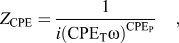
The EIS was used to evaluate the charge transfer and ion diffusion properties of the electrode materials. EIS measurement was conducted at the frequency range of 100 kHz–0.01 Hz, the open circuit potential of 0 V and an arc perturbation of 5 mV. Figure 6(A) shows Nyquist plots of EIS for MnO2/RGO mixture composite and MnO2/RGO double-shelled hollow microsphere. The enlarged plot at the high frequency region is shown in the insert. Figure 6(B) shows the equivalent circuit of above EIS Nyquist plots. It involves the equivalent circuit elements of ohmic resistance (R o), charge transfer resistance (R ct), constant phase element (CPE), and Warburg diffusion element (W). The ohmic resistance includes resistance of electrolyte, intrinsic resistance of electrode material, and contact resistance at interface of electroactive material and current collector. The impedance of CPE (Z CPE) can be expressed as the formula (1).
 $${Z_{{\rm{CPE}}}} = {1 \over {i{{({\rm{CP}}{{\rm{E}}_{\rm{T}}}\omega )}^{{\rm{CP}}{{\rm{E}}_{\rm{P}}}}}}}\quad ,$$
where ω is the angular frequency and i is the imaginary number; CPET is the capacitance when CPEP = 1; CPEP is the constant phase element exponent.
Nyquist plot of EIS and the corresponding simulation curves of MnO2/RGO mixture composite and MnO2/RGO double-shelled hollow microsphere in 0.5 M Na2SO4 electrolyte solution.
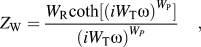
The Warburg diffusion impedance (Z W) can be expressed as the formula (2).
 $${Z_{\rm{W}}} = {{{W_{\rm{R}}}\coth [{{(i{W_{\rm{T}}}\omega )}^{{W_{\rm{P}}}}}]} \over {{{(i{W_{\rm{T}}}\omega )}^{{W_P}}}}}\quad ,$$
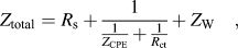
where W R is the diffusion resistance (Warburg diffusion resistance); W T is diffusion time constant, and W P is a fractional exponent between 0 and 1. W T is equal to  ${{{L^2}} \over D}$, where L and D are the effective diffusion length and diffusion coefficient, respectively. The total electrochemical impedance (Z total) of the equivalent circuit can be expressed as the formula (3).
 $${Z_{{\rm{total}}}} = {R_{\rm{s}}} + {1 \over {{1 \over {{Z_{{\rm{CPE}}}}}} + {1 \over {{R_{{\rm{ct}}}}}}}} + {Z_{\rm{W}}}\quad ,$$
The fitting curves of the equivalent circuit were obtained using the Zview software. The electrochemical impedance was calculated using above formula and equivalent circuit elements. The good fitting results implied that the equivalent circuit model could reasonably reflect the occurred electrochemical process. Table I lists the fitting values of the equivalent circuit elements of MnO2/RGO mixture composite and MnO2/RGO double-shelled hollow microsphere. Accordingly, the R o value was slightly decreased from 1.1471 Ω for MnO2/RGO mixture composite to 0.8778 Ω for MnO2/RGO hollow microsphere. The corresponding R ct value was obviously decreased from 2.6801 Ω to 0.3006 Ω. Lower ohmic resistance demonstrated higher electrical conductivity for MnO2/RGO hollow microsphere. Usually, the electrochemical impedance spectrum consists of a semicircle or circular arc at the high frequency region and a straight line at the low-frequency region. MnO2/RGO hollow microsphere exhibited a smaller semicircle or circular arc diameter than MnO2/RGO mixture composite, indicating the smaller charge transfer resistance of MnO2/RGO hollow microsphere in the electrochemical process. The slope of the fitting curve at low frequency region was called the Warburg resistance (Z W) and was a result of the frequency dependence of ion diffusion/transport in the electrolyte to the electrode surface.Reference Stoller, Park, Zhu, An and Ruoff39 The Z W value was also decreased from 5.79 Ω to 1.47 Ω. Comparing the slope of the beeline at low frequency region, MnO2/RGO hollow microsphere exhibited larger slope, indicating a smaller ion diffusion resistance and higher capacitance performance than MnO2/RGO mixture composite. So, MnO2/RGO hollow microsphere exhibited smaller values of R o, R ct, and Z W than MnO2/RGO mixture composite. The Z total was accordingly decreased from 6.94 Ω for MnO2/RGO mixture composite to 2.37 Ω for MnO2/RGO hollow microsphere. It indicates that the well-design structure of double-shelled hollow microsphere could effectively improve the electrical conductivity and ion diffusion of MnO2/RGO electrode material.
Fitting values of the equivalent circuit elements of MnO2/RGO mixture composite and MnO2/RGO double-shelled hollow microsphere.
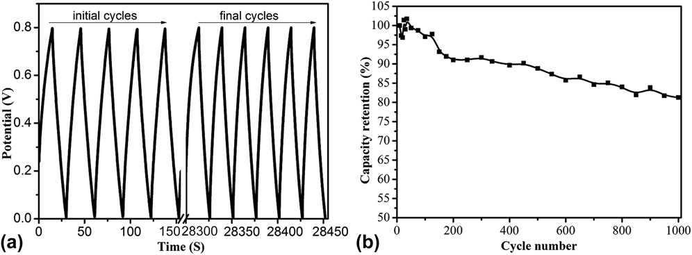
In order to evaluate the cycle stability, MnO2/RGO double-shelled hollow microsphere conducted continuous charge–discharge process for 1000 cycles at a high current density of 5 A g−1 and a potential window from 0 to 0.8 V. Figure 7 shows continuous GCD curve and capacitance retention curve of MnO2/RGO double-shelled hollow microsphere. The specific capacitance declined from 193.2 to 157.8 F g−1 and correspondingly kept about 81.7% capacitance retention even after 1000 cycles, which was comparable to or even better than other manganese oxide-based capacitance.
(a) Continuous GCD curve and (b) capacitance retention curve of MnO2/RGO double-shelled hollow microsphere at a current density of 5 A g−1 in 0.5 M Na2SO4 electrolyte solution.
IV. CONCLUSIONS
MnO2/RGO double-shelled hollow microsphere was well prepared through GO adsorption on the surface of PS microsphere, chemical reduction of GO, in situ deposition of MnO2 and chemical etching of PS. The large surface area and excellent electrical conductivity of MnO2/RGO double-shelled hollow microsphere contributed to a high specific capacitance 450.1 F g−1 at a density of 0.2 A·g−1. It also kept a good rate capability and high capacitance retention of 81.7% after 1000 cycles at a high current density of 5 A g−1. MnO2/RGO double-shelled hollow microsphere showed a very promising application as the highly-performed supercapacitor electrode.
ACKNOWLEDGMENT
The work was supported by National Natural Science Foundation of China (No. 21373047).