NOMENCLATURE
- B
-
element width parallel to the delamination
-
 $c_{c}$
-
weighting factor
- F
-
force
- f
-
fracture criterion
- G
-
energy release rate
- n
-
element node
- da
-
element length normal to the delamination
- dbt
-
time of delamination failure
-
$\delta u$
-
separation
-
${\chi _{F}}$
-
interaction parameter
- DCB
-
double cantilever beam
- CFRP
-
carbon-fibre-reinforced plastic
- ENF
-
end-notched flexure
- ERR
-
energy release rate
- FINAF
-
Finnish Air Force
- MMB
-
mixed-mode bending
- TEF
-
trailing-edge flap
- VCCT
-
virtual crack closure technique


1.0 INTRODUCTION
Continuing airworthiness is one of the main concerns for aging fighter aircraft operation. The requirements of high performance and loading-intensive operation during training and missions make the maintenance and repair actions challenging as the operational hours of the aircraft accumulate towards the full lifetime. For metal-composite airframes, the structural deficiencies observed include premature fatigue of metal fuselage frames and delaminations of composite laminates, to mention but a few of them(Reference Mueller, Starnes, Strickland, Kenny and Williams1). The current fighter fleet of the Finnish Air Force (FINAF) consists of 62 F/A-18 Hornet aircraft. The fleet includes one- and two-seat C/D models. The first Hornet was delivered to the FINAF in 1995. The first plane of the fleet is expected to be retired in the year 2025. The structural integrity of the airframes is under the responsibility of the Finnish Defence Force Logistics Command. Along with the standard procedures for continuing airworthiness, industrial and academic research projects are constantly run to develop new repair methods and enable more accurate assessment of residual fatigue lives(Reference Viitanen, Varis and Siljander2).
One of the most challenging issues regarding the structural wear of the FINAF F/A-18 fleet is the criticality of delamination defects. Delamination is a type of damage that forms between the reinforcement plies of a composite laminate(Reference Wisnom3,Reference Bolotin4) . After its emergence, delamination damage may grow due to the relatively low fracture toughness of interlaminar cracks(Reference Hintikka5,Reference Partridge and CartiÉ6) . Since delamination significantly affects stiffness and the overall load-carrying capability of composite parts(Reference de Moura, Campilho, Amaro and Reis7,Reference Senthil, Arockiarajan, Palaninathan, Santhosh and Usha8) , the potential for delamination growth at design loads must be analysed for each observed delamination case. The analysis is complicated and becomes even more challenging when multiple, possibly interacting, delaminations exist. Brouzoulis and Fagerström stated that the typical delamination analysis approach is to model each ply interface(Reference Brouzoulis and FagerstrÖm9), which requires directly modelling each ply in the laminate. They studied modelling in a structural case using only one shell element in the thickness direction. Liu and Zheng analysed the buckling, post-buckling and delamination of multiple delaminations in symmetrical and unsymmetrical laminates(Reference Liu and Zheng10). The asymmetry of the laminate was shown to largely influence the delamination and buckling behaviour when delaminations were small. Chen and Fox developed a modified cohesive model for analysing multiple delaminations in the T-section(Reference Chen and Fox11) of an aero engine blade structure. They noticed that the T-piece had much better resistance to a pulling load case than a bending load case. Experimental observations are important, along with the simulated predictions. It should be noted that non-destructive inspection of multiple delaminations might not be accurate when traditional ultrasound techniques are used(Reference Chen and Fox11). Ryu et al.(Reference Ryu, Park, Kim, Jhang and Kim12) studied multiple delamination inspections using terahertz time-domain spectroscopy, which provided accurate results.
The work at hand presents the approach used for analysing delamination damage in the FINAF. First, the work describes the tests that are used for defining the fracture toughness values of laminates and allowable critical energy release rates (ERRs) for fracture criteria. This is followed by a description of the numerical analysis procedures and methodologies that are used in delamination analyses. In the scientifically important part of the work, the criticality of multiple delaminations is also studied in ply interfaces other than the interface where the delaminations were assumed to exist. The current literature on laminate delamination analyses focuses on a single delamination(Reference Riccio, Giordano and Zarrelli13,Reference Shen, Lee and Tay14) . Analysis of multiple delaminations is a complex task due to the challenging experiments and numerical analyses, with dependence on the way the codes are run. Published studies are scarce, and the interaction between multiple delaminations of arbitrary shape has not been reported. In this study, in addition to multiple delaminations, the ply-interface effect on the delamination interaction is also considered. The practical application, that is, the case study structure, is the F/A-18 Hornet fighter’s trailing-edge flap (TEF), where delaminations have been observed around the fastener holes of the spar web laminate. Based on the applied work on delaminations, the virtual crack closure technique (VCCT) was used for the crack (front) modelling in the analysis. The VCCT analysis, using an experimentally determined fracture criterion, was applied for two existing TEFs with delamination damage. The delamination cases were also studied by varying the interface of delamination, i.e. by assuming delaminations located at different ply interfaces. Additional virtual cases were also created to study the interaction of multiple delaminations and determine the differences in the fracture behaviour when the delaminated interface is varied. The results indicate that changing the interface can have a significant effect on the delamination’s criticality. The interaction of the applied multiple delaminations was seen to be minor in the current analysis case.
The DCB, ENF and MMB specimens needed to characterise a composite laminate for fracture analyses(Reference Jokinen15).

2.0 MATERIALS AND METHODS
2.1 An experimentation programme for determining fracture toughness values
Experiments are needed to define fracture mechanics properties that are specifically related to the materials used in real structures. For the FINAF, an experimentation programme was established in 2008 to measure the fracture toughness values of composite materials. The survey part of the program(Reference Hintikka5,Reference Jokinen15) included surveying literature studies on existing experimental and numerical methods. Standardised tests have been developed for fracture mode I and II delaminations in fibre-reinforced plastic composites and adhesive joints. The most typical fracture mode I and II specimens are, respectively, double cantilever beam (DCB) specimens(16) and end-notched flexure (ENF) specimens(17). The DCB and ENF tests provide critical ERR values, G IC and G IIC. They represent the interlaminar fracture toughness per mode and can be used as limit values for nodal release in numerical, finite element (FE) analyses. It is important to note that a study of single-mode loading could lead to a non-conservative result for delamination propagation. For this reason, methods with specific test specimens have been developed to study mixed-mode failure. For example, the mixed-mode bending (MMB)(18) method has been used for the purpose. Unfortunately, such methods only produce modal fracture toughness values, and an interaction function(Reference Benzeggagh and Kenane19,Reference Reeder20) must be established to predict fractures in a general case.
The experiments carried out included DCB, ENF and MMB experiments (see the concepts in Fig. 1) for carbon-fibre reinforced plastic (CFRP) specimens. The first phase of the experimental programme was performed during 2009–2017, and its main results have been reported at ICAS congresses and in the form of reviews of national investigations at ICAF congresses(Reference Viitanen, Varis and Siljander2,Reference Hintikka, Wallin and Saarela21,Reference Jokinen, Wallin and Saarela22) . The test matrix was generated for CFRP laminates with 24 plies, resulting in a total laminate thickness of 3.5mm. The stacking sequence of all the studied laminates was 0°; that is, the laminates were unidirectional (UD), corresponding to the standards. When evaluating the results, it must be noted that fibre bridging in the 0°/0° interface of standard test specimens typically resists crack, propagation resulting in higher critical ERR values when compared with those of other types of interfaces. The interface effect on ERR values was noticed to be less than 30% in the worst case(Reference Hintikka5). Thus, since critical ERR values were defined with standard test methods and delamination analyses were performed for different types of interfaces in two dimensions, the analysis results are believed to be non-conservative to some extent. The material of the specimens was carbon/epoxy prepreg AS4/3501-6 (Hexcel®). The specimen width in all tests was 20mm. The specimen length was 125mm, 120mm and 137mm for the DCB, ENF and MMB specimens, respectively. A pre-existing crack was positioned in the middle of the specimen. The initial crack lengths were 64mm, 35mm and 50mm for the DCB, ENF and MMB specimens, respectively. The specimens were cured in an autoclave, and white marker was applied for crack length measurements (Fig. 2). The tests were performed in ambient laboratory conditions. An additional test matrix was generated to initially study fracture properties at high temperatures(Reference Hintikka, Wallin and Saarela21).
The DCB and ENF specimen configurations used for the tests in the FINAF research programme(Reference Hintikka, Wallin and Saarela21).

All test series included five specimens. The tests were performed using a universal servo-hydraulic tensile test machine with a 100-kN main load cell. A separate load transducer of 0.5kN was used in the DCB and MMB tests to record the lower end of forces. The ENF testing was performed using the force transducer of the tensile test machine. Either a movable microscope or crack strain gauge was used for visual observation of crack propagation, and the results were recorded synchronously with the test machine. The test procedures and results are reported in detail in the thesis written by Hintikka(Reference Hintikka5).
Since several different (alternative) analysis equations exist for the standard interpretation of DCB and ENF results, it is necessary to run numerical analysis alongside experiments. For the FINAF experimentation programme, analyses were included to verify the critical ERR values. A survey for comparing the applicability of the existing numerical methods was included in the programme, and the main outcomes are reported in the thesis written by Jokinen(Reference Jokinen15). Due to the high requirements set for reliability and clarity, the VCCT was selected for the primary simulation method.
2.2 The VCCT
The VCCT method is a common technique for delamination analyses(Reference Shokrieh, Rajabpour-Shirazi, Heidari-Rarani and Haghpanahi23). The VCCT is based on FE analysis, wherein ERR values are evaluated using the nodal reaction force and displacements at the crack tip(Reference Wang and Raju24). Using the basic equation of the VCCT, the ERR value can be computed using the equation
 \begin{equation}{G_{\rm{I}}} = {{F\delta u} \over {2Bda}},\end{equation}
where
 $F$
is the reaction force,
 $\delta u$
is the separation between nodal points adjacent to the crack tip, B is the element width parallel to the delamination edge and da is the element length normal to the delamination edge. The parameters are characterized in Fig. 3. The history, theory and applications of the VCCT have been reviewed by Krueger(Reference Krueger25).
The VCCT crack tip definition for FE analysis.

The VCCT has been used in many structural analysis cases, including coupon-level delaminations in composite materials and fibre–metal laminates(Reference Jokinen15,Reference Jokinen and Kanerva26-Reference de Morais, de Moura, GonÇalves and Camanho28) for example. Recently, the VCCT was used in an accident investigation into a glass-fibre-reinforced leaching reactor(Reference Lindgren, Bergman, Kakkonen, Lehtonen, Jokinen, Wallin, Saarela and Vuorinen29). The debonding of adhesive joints has also been successfully studied using the VCCT(Reference Jokinen, Wallin and Saarela30,Reference Aakkula, Jokinen and Saarela31) , although the method is typically considered to only be appropriate for brittle delaminations.
2.3 The TEF of an F/A-18 C/D
The structure being studied is an aircraft component with a heavy air load, composite primary structure and observed damage. This component is the TEF of the F/A-18 C/D Hornet aircraft of the FINAF (Fig. 4). The TEF is attached to the wing of the F/A-18 with an inboard and outboard lug. Figure 4 visualizes the aerodynamic load and connection point (reaction) loads of the TEF. The lugs transfer the aerodynamic loads to the wing’s primary structure. The inboard lug includes the actuator connection defining the TEF deflection. The lugs are attached to the TEF’s CFRP spar. The spar laminate is made of 15 AS4/3501-6 prepreg plies with a stacking sequence of [45/–45/0/45/–45/45/–45/90/–45/45/–45/45/0/–45/45]. The ply coordinate direction (0°) is set here such that it is parallel to the spar’s spanwise direction.
The location of the TEF on a FINAF F/A-18 C/D Hornet(32) (on the left) and the schematics of the TEF’s loading (on the right).

This study focuses on the outboard lug and its attachment to the composite spar web. The outboard lug is attached to the spar web with six fasteners forming a trapezoidal pattern. In addition to six fasteners, the lug is attached to spar flanges with eight fasteners (four top and four bottom). The fastener pattern in web with dimensions is shown in Fig. 5. The symmetry line, in the vertical direction, is in the middle. The diameter of each fastener hole in the spar web is 5.0mm. The connection of the lug is under intensive loading during flight, and delaminations have been found amidst the spar web fastener holes within FINAF control surfaces.
Delaminations (dashed lines) existing around fastener holes of the TEF composite spar web(Reference Jokinen, Wallin and Saarela22).

The TEF’s lug was removed for modification for each of the FINAF’s F/A-18s during the mid-life upgrade (MLU) programme. The ultrasonic inspection method was performed for the composite spars after the old lugs were removed. The inspection revealed delaminations around the fastener holes. These delaminations are thought to be caused by installation or removal of the lug or to have occurred due to unexpected loadings. The type of the fastener is a blind bolt without access to the rear side of the spar web. Therefore, the fasteners were drilled out to remove the lug from the composite structure. This removal process might have caused excessive out-of-plane loads to the hole surroundings in the real structure. As noted above, another possible cause for delamination is unexpected laminate loading wherein interlaminar stresses exceed the local durability. Two TEFs with delaminated spars were selected for detailed analysis. The delaminations were located around the fastener holes that are used to connect a lug to the composite spar structure. The delaminations are illustrated in Fig. 5. The first damaged spar included one delamination (case A), while the second damaged spar had two delaminations (cases B1 and B2). Based on the inspection results, the delamination in case A was estimated to be at the 13th and 14th ply interface, while the delaminations in cases B1 and B2 were estimated to be at the 11th and 12th ply interface. The interface coding is calculated by starting from the front side of the spar web.
The TEF sub-model with boundary conditions and the relation to the aircraft global model (the composite spar web is highlighted red).

2.4 FE analysis
2.4.1 Structure and model description
The delaminations detected in the TEF spars were regarded as potentially critical for the safety of the component and aircraft. Therefore, the criticality of the delaminations was evaluated using a numerical analysis. The TEF case is an example indicating the importance of the performed experimentation programme for determining the fracture toughness of composite materials.
To analyse the criticality of the observed delaminations, a specific numerical (FE) sub-model of the TEF was built using commercial Abaqus/Standard (Simulia) FE software. The load condition and the deformation related to the flight condition were derived from large-scale FE models of (1) the entire aircraft and (2) the TEF sub-model, as presented in Fig. 5. The sub-model of the TEF was mainly meshed with shell elements representing the TEF’s outer surfaces and the lugs. The material models applied in the FE analysis were all linear elastic. The sub-model was analysed using one load condition, which was predefined by Patria Aviation(33). The loading and the relation to the global FE model were created using enforced displacements at the sub-model’s (free) edges and the lug.
To focus the computational efforts on the critical area, a sub-model of the TEF’s composite spar web was further created. When the modelling was focused on a smaller portion of the structure, the level of details and the mesh density were increased proportionally. The spar sub-model was created so that it covered the outboard lug’s connection area. The sub-model was a 330-mm-long (horizontal) portion of the entire spar. This portion excluded the inboard lug and most of the TEF parts other than the spar. The location of the spar sub-model in the TEF model is highlighted in red colour in Fig. 6.
The spar sub-model was divided into two sub-laminates in the laminate thickness direction to define the delamination interface. The front-side sub-laminate was attached to the upper and lower flanges of the TEF sub-model. The boundary conditions (BCs) were applied at the spar edges limited by the size of the spar sub-model. The fasteners connecting the lug and the TEF were modelled using the connector elements. The connector elements were located at the middle of the connection (pattern region). The locations of a delamination and the connector between the spar web and the lug are described in Fig. 7.
The fastener loading in terms of force components in this study(Reference Jokinen, Wallin and Saarela22)

Illustration of the fastener area modelling with VCCT application (on the left) and the sideway (cross-section) at the delamination (on the right).

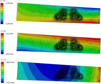
The fastener loads in the studied loading condition are listed in Table 1. For the BCs at edges, the vertical edges and the vertical partition line (Fig. 8) were restricted in terms of rotations. BCs using enforced displacements were defined at three nodal points at the edge. The enforced displacements were −2.3, −5.3 and −16mm in the global xyz-coordinate system, respectively. Finally, the spar web sub-model’s loading was the result of the BCs of the vertical edge, connector elements and BCs at horizontal edges due to flanges of the TEF sub-model. The deformation field of the intact spar web in the global coordinate system, when excluding delaminations, is shown in Fig. 9.
The geometry of the spar web finite element model including the partitions made to better define the element mesh.

Displacement field of the TEF spar web that determines the loading in the spar web with the given material (model) of the CFRP laminate. The displacement U1 is in the horizontal direction and U3 is in the vertical direction (U2 is normal to U1 and U3 when following the right-hand rule, respectively).

The exact geometry of the spar web sub-model is shown in Fig. 8. The horizontal length of the sub-model is 330mm. The spar web is slightly tapered so that its height decreases from 70 to 62.5mm (from left to right in Fig. 8). The sub-laminates’ stacking sequences were given in Abaqus to define the sub-laminate stiffnesses based on the AS4/3501-6 ply properties. The ply material was presumed to behave as linear elastic material. The following properties were used for the ply: E 1 = 140GPa, E 2 = 10GPa, G 12 = 5.7GPa and ν 12 = 0.3. The ply thickness of 0.13mm was used everywhere in the sub-model. The use of two sub-laminates means that two equal spar web geometries, modelled as shells, were assembled to form the sub-model. The offset of these sub-laminate shells was set to the surface at the delamination interface; i.e. the sub-laminates were not modelled based on their midplanes, as would be normal in general FE models. The total thickness of the sub-laminates corresponded to the thickness of the spar laminate formed from 15 plies. The sub-laminate’s modelling using the shell elements allowed easy modification of the delamination location. However, this approach limited the delaminations to exist only at one of the ply interfaces per simulation run. The spar sub-laminates were modelled using conventional shell elements (S4 element in Abaqus). Typical element dimension by edge length was 0.5mm around delaminations and 4.0mm elsewhere in the model.
The delamination plane at the laminate interface, for VCCT application, was defined to analyse the start of delamination propagation (from the modelled pre-crack) and its growth after the start of delamination. The delamination plane was located between the sub-laminates. The front sub-laminate was defined as the master surface of the VCCT interface. The fastener areas (Fig. 8) were modelled as continuous plies including a contact definition. This means that separate fastener holes were not modelled, which simplified the sub-model’s usage. In the multiple delamination analysis, circular delaminations, i.e. pre-cracks, were modelled around the fasteners, as described in Fig. 7. The VCCT’s crack tip was defined based on the above contact definitions. The interfacial area inside the delamination edge was given the contact definition based on the Abaqus-implemented VCCT definition. The option of geometric nonlinearity available in Abaqus was included, but it had only a minor influence on the analysis results, since the displacements remained at a low level throughout the sub-model.
2.4.2 Multiple delamination study
An in-depth delamination study was carried out to better understand the criticality of the delaminations around the TEF spar web fastener holes. The aim was to study the influence of multiple delaminations on the start of delamination propagation. For this purpose, seven artificial pre-delamination patterns were created (Table 2). The diameter of each delamination was set to 15.24mm (0.6inches). The effect of multiple delaminations was studied by taking into account the fact that they may emerge at different interfaces of the spar laminate.
Pre-delamination combinations for analysing the criticality of the start of multiple-delamination propagation in an F/A-18 TEF structure

The first analysis indicated that the applied delamination size does not provide an ERR level that would result in the start of delamination propagation with the applied fitted fracture criterion and with the applied load case. For this reason, the fracture criterion was modified while the load case was preserved. The critical ERR G IC and G IIC values were divided by a single factor (=10) in the modified criterion. This modification allowed studying the interaction of multiple delaminations as the delamination starts to grow. The delamination propagation was allowed in the VCCT implementation in Abaqus for an event where the fracture criterion is fulfilled. The default settings of Abaqus were used for running the VCCT analyses.
Abaqus (Standard) executes the applied external loading in one analysis increment by default. The analysis is characterised by the analysis time, which achieves the value of unity (100%) when the external loading is fully subjected to the model. The defined external loading may not be achieved in one increment, and a cutback might be required if the software’s rules of equilibrium, convergence and VCCT tolerance are not satisfied. The procedure of a VCCT analysis in Abaqus is characterized in Fig. 10. This is typical when nonlinearities, such as delamination propagation, exist during the increment. The cutback reduces the (load) increment and performs a new increment by applying a part of the original external loading. The new increment and cutback are accepted when the software criterion is satisfied. The dbt parameter is used in this work to identify the criticality observed in terms of the numerical analysis. In practice, the parameter dbt is defined as the analysis time reached when the first nodal point exhibits delamination failure. The dbt is shown as a per cent value (a fraction of the analysis time). The dbt can be extracted using the following equation:
 \begin{equation}{\rm{dbt}} = {{{F_{delamination\ onset}}} \over {{F_{total}}}},\end{equation}
where F is the ‘load’ described by the external force or enforced displacement used to activate the analysis.
The procedure of the VCCT analysis in Abaqus (Standard) and as applied here for a multiple delamination study.

3.0 RESULTS
3.1 Fracture properties defined for the CFRP
Realistic material definitions are of major importance when the criticality of a safety-affecting aircraft component is analysed. The main material definitions applied for composites in the FINAF experimentation programme are briefly described here for the study of multiple delaminations.
Critical ERR values for different fracture modes form the basis for the material mechanics of VCCT fracture analyses. The applied DCB insert cycle tests of the experimental programme provided the critical ERR value of 72 ± 8J/m2, which was used as the G IC value. The ENF testing resulted in the G IIC value of 779 ± 48J/m2. The MMB testing was carried out using mixed-mode ratios (G II/(G I + G II)) of 0.2, 0.5 and 0.8. The results of the DCB, ENF and MMB tests, as used in the multiple delamination study, are summarised in Fig. 11. The critical values are combined to form the fracture mode interaction function, f. The experimental testing for the interaction function was performed by Hintikka(Reference Hintikka5). It is important to note that the functional form depends on the fitting procedure. The fracture function was defined as a power law and took the following form(Reference Hakuri34):
 \begin{equation}f = {\left( {{G_{\rm{I}}}/72} \right)^{0.75}} + {\left( {{G_{{\rm{II}}}}/779} \right)^{0.69}}.\end{equation}
Based on the definition, the fracture occurs when the function equals to one.
The fracture criterion versus the experiments, as used in the multiple-delamination study for CFRP (AS4/3501-6, Hexcel)(Reference Jokinen, Wallin and Saarela22).

3.2 Analyses of the observed delaminations
The analysis results for the observed delaminations form a baseline for multiple damage analyses. In delamination case A, the delamination was located around the fastener c, as described in Fig. 5. The VCCT analysis results for this case are presented in Table 3 with the ERR values of each fracture mode and the fracture function value after completing the given load case. Three analyses were performed, since the interface of the real delamination was not exactly known. The assumed location was between the 13th and 14th ply, based on ultrasonic inspection(Reference Jokinen, Wallin and Saarela22). The results indicate that delamination loading is shear dominated because the ERR value of fracture mode I is negligible with all the studied delamination interfaces. The values further show that the ERR and fracture function values are relatively low. Thus, it can be concluded that delamination propagation is unlikely. The delamination interface closest to the laminate mid-plane provides the highest criticality.
The computed ERR and fracture function values of the delamination A(Reference Jokinen, Wallin and Saarela22)

Corresponding results for delamination cases B1 and B2 are presented in Tables 4 and 5 respectively. Delamination B1 is seen to be more critical than delamination A, but according to the analysis result, the applied load does not result in failure (delamination growth). With the small delamination, B1, the assumed location of the delamination (11th and 12th)(Reference Jokinen, Wallin and Saarela22) provides the smallest value of the fracture function (Equation (3)). With the larger delamination, B2, the fracture function value increases when the delamination is shifted towards the laminate mid-plane.
The computed ERR and fracture function values for the delamination B1(Reference Jokinen, Wallin and Saarela22)

The computed ERR and fracture function values of the delamination B2(Reference Jokinen, Wallin and Saarela22)

3.3 Multiple delamination analysis
The delamination analyses were proceeded by studying artificial patterns of multiple delaminations. The results of the analyses are shown in terms of the dbt value in Fig. 12. It can be seen that case 3 distinctively differs from the rest of the cases; that is, the start of delamination propagation load of this case is clearly the highest. This indicates that the delaminations a, b and c that are included in case 3 are less critical than the other delaminations. Otherwise, the difference between the analysis cases (i.e. excluding case 3) is slightly above 5%.
The start of delamination propagation in different multiple delamination cases, expressed in terms of the analysis time (dbt)(Reference Jokinen, Kanerva and Saarela35).

Multiple delamination analyses were initially performed by assuming delaminations located at the ply interface 11/12 (i.e., between the 11th and 12th ply). The analyses were continued to cover five other ply interfaces. The results of this survey are shown in Fig. 13. The most dramatic change occurs with delaminations at the interface 7/8, resulting in an almost 60% decrease in dbt for cases 1, 2 and 6. A similar but less dramatic change occurs in these cases when delaminations are located at the interface 9/10. The results obtained with the delamination interface 8/9 only show a marked difference for case 1’s pattern. The delamination interface 10/11 provides results similar to the delamination interface 11/12, except for case 3’s pattern. The delamination interface 12/13 leads to slightly increased dbt values (from 10% to 20%, depending on the pattern).
Delamination performance and the interfacial effect on the start of delamination propagation.

Figure 14 presents the effect of the delamination interface. In cases 1–3 and 6, when placing delaminations towards the laminate middle surface, the dbt value decreases, meaning increased crack tip loading. In cases 4, 5 and 7, the trend is the opposite and changes are relatively small. None of the trends are monotonic.
The start of delamination propagation in multiple-delamination cases with different delamination interfaces.

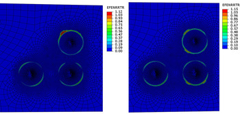
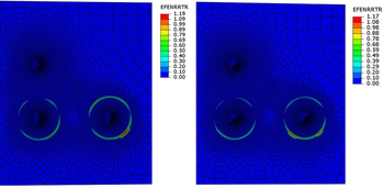
Some multiple delamination analyses were continued to the delamination propagation phase. Figures 15 and 16 show the propagation at the interfaces 7/8 and 11/12in cases 3 and 6, respectively. The parameter ‘EFENRRTR’ describes the fracture criterion value around fastener holes. A value of 1 refers to delamination. The value level is shown by colours (blue refers to no delamination) that illustrate how delamination proceeds from the original circular nodal line of the initial delamination. Figures 15 and 16 represent a roughly 20% increase in loading after the start of delamination propagation. In case 3, at the interface 11/12, delamination growth is seen to be limited to a single hole surrounding and to one direction. At the interface 7/8, delamination has propagated around two holes and in two directions. In case 6, only one initial delamination has propagated at the studied interfaces. Similarly to in case 3, the delamination propagation has, respectively, one and two preferred directions at the interfaces 11/12 and 7/8.
Delamination growth in case 3 at the interfaces 11/12 (on the left) and 7/8 (on the right).

Delamination growth in case 6 at the interfaces 11/12 (on the left) and 7/8 (on the right).

To compare different simulation cases in terms of the delamination interaction, an equation for describing the multiple-delamination interaction was developed. It was based on the geometry-related interaction. In other words, the interaction refers to the ability of neighbouring pre-delamination sites to affect the extent and directionality of delamination growth.
To start with, the fastener hole and delamination with the highest growth were defined for all the pre-delamination cases (i.e. the cases in Table 2). Hence, the direction of the reference delamination for each pre-delamination case was defined according to the site (e.g. a fastener hole) and the direction of highest delamination growth, as illustrated in Fig. 17.
The definitions of the delamination’s reference direction and the related directions ( j = 1…4).

The extent of growth in an FE analysis is given by the amount of delaminated element nodes (n) and can be computed per fastener hole and in different defined directions (given by the sub-index j). Now, for a fastener hole and all its directions, the nominal delamination growth is defined as
 \begin{equation}\mathop \sum \limits_j^m {n_j},\end{equation}
where the index j runs from 1 to 4 for the circular fastener hole with the directions as defined in Fig. 17. To account for interaction, a configuration with several damage sites is needed, such as the lug connection point in this study. The cumulative delamination growth is defined as
 \begin{equation}\mathop \sum \nolimits_i^k \mathop \sum \limits_j^m {n_{ij}},\end{equation}
for, in total, k number of potential delamination sites. Since the nominal delamination for a pre-delamination case is calculated cumulatively for four directions and all the sites, Equation (5) is a rather good measure of delamination growth for a pre-delamination case. To indicate the effect of interaction in terms of changed delamination direction, the delamination growth in the reference direction and at the site of highest delamination is separated as its own term with a factor (
 ${c_c} \in {\mathbb{Z}_{+}}$
) to adjust the weight between the terms:
 \begin{equation}\left( {{c_c} - 1} \right) \cdot {n_d} + \mathop \sum \nolimits_i^k \mathop \sum \limits_j^m {n_{ij}},\end{equation}
where the sub-index d refers to the fastener hole with the highest nominal delamination growth and its reference direction.
The absolute interaction must be normalised with respect to a general pre-delamination case (given the sub-index 0), that is, to all the fastener holes active (here, case 1 in Table 2). This configuration always has a non-zero delamination growth at the load condition applied, by definition. The formulation of delamination interaction finally takes the following form:
 \begin{equation}{\chi _F} = {{\left( {{c_c} - 1} \right) \cdot {n_d} + \mathop \sum \nolimits_i^k \mathop \sum \nolimits_j^m {n_{ij}}} \over {\mathop \sum \nolimits_i^k \mathop \sum \nolimits_j^m {n_{0,ij}}}},\end{equation}
where the numerator describes the studied pre-delamination case and the denominator the reference pre-delamination case. Clearly, if the variant pre-delamination case has matching delamination interaction with the reference case, the interaction parameter returns unity with the value 1 for the weighting factor
 ${c_c}$
.
It should be noted that the term with the summation over several sites (here, fastener holes) and directions tends to reach a larger value compared with the single-site value n
d
. Therefore, to balance the weight between these terms, the factor
 ${c_c}$
may be given a non-unity value. In this study, the results were computed with the values 1 and 2 for the weighting factor.
The quantified interaction results for each delamination case are shown in Table 6. These results are evaluated for anticipated delaminations at the interface 11/12. The start of propagation for calculating the values is determined at a 20% load increase when compared with the results presented in Fig. 12. Table 6 presents the values of the interaction parameter
 ${\chi _F}$
with the two values for the weighting factor. The results indicate that the interaction parameter remains below 1 when the weighting factor is 1. This indicates that the largest growth and interaction occur in the reference case. The results also show that an increase in the weighting factor increases the interaction parameter values, but the interaction rank between different pre-delamination cases is not sensitive to the selected value of the factor c
c
.
The start of delamination propagation in fastener holes at 1.2 times the dbt load level (the red colour emphasizes a delamination site where significant propagation occurs)

4.0 DISCUSSION
Multiple damage interaction is a complex phenomenon dependent on materials, structure and loading. A solid metal material with embedded cracks was studied in Ref. (Reference Azuma and Li36, Reference Yan and Miao37). The study of multiple damage in aeroplane structures has naturally attracted attention in literature. Metal shell structures with longitudinal riveted joints under fatigue loading are potential multisite damage objects in which small fatigue cracks may initiate around rivet holes. Galatolo and Nilsson studied experimentally and numerically the residual strength of such joints(Reference Galatolo and Nilsson38). Their study revealed an interaction of elastic-plastic deformation and crack propagation. The study by Park et al.(Reference Park, Singh, Pyo and Atluri39) remarked that rivet holes ahead of the lead crack reduce residual strength dramatically. Lately, Wang et al.(Reference Wang, Rans, Alderliesten and Benedictus40) has studied fibre metal laminate multi-site damage using an analytical solution.
The TEF structure studied in this paper has multiple fasteners in a region where delaminations around several holes may exist. For this reason, TEF presents a challenging and interesting case for multiple delamination analysis. Of course, multiple delamination analysis is complex, especially when describing the practical structure with its geometry, lay-ups and thickness at each location. The aim of our current analysis is to study whether such multiple delamination exhibits an interaction that cannot be neglected. Based on the results, we made the following definition of interaction:
-
• Interaction refers to a different direction of delamination growth when an adjacent delamination exists (compared with the case with a single delamination);
-
• Interaction refers to different level of ERR at delamination when an adjacent delamination exists (compared with the case with a single delamination).
Due to the practical real-world example, the analysis was performed for a 3D structure. A model was developed to quantify the interaction. Knowledge about the level of interaction is important because a strong interaction will significantly influence the crack tip ERR. A strong interaction indicates that criticality assessment of delaminations cannot be performed independently, which is currently typical procedure.
To study the criticality of an observed delamination in aircraft composite structures, both experiments and numerical computations are needed. Experimental testing and its data analysis based on fracture mechanics were performed for this work by using DCB, ENF and MMB test procedures. The fracture criterion for multi-mode fractures was also defined based on these experiments. All the experiments were performed using UD laminates defined by experimental standards. The delamination interface in a UD laminate naturally lies between zero-angle plies, which is relevant in specific laminate structures. Of course, a delamination does not typically run straight along its edge. The experimental work by Hintikka(Reference Hintikka5) also covered laminates with other stacking sequences and delamination interfaces; the delamination interface was seen to influence the critical values. The UD interface 0 ˚/0 ˚ was the most conservative in the DCB test, but not in the ENF test.
The numerical fracture analysis results are dependent on the software’s (Abaqus’s) ERR tolerance, in addition to the location of the critical interface. The start of delamination propagation-related load level can vary because the tolerance value allows the values given by the applied fracture criterion to be exceeded. This is also related to the load increment applied in the analysis, which can also be controlled by the user. The default tolerance value in Abaqus/Standard is 20%. Based on our analysis, the tolerance value and the incrementation only had a minor effect on the start of delamination propagation in terms of the load level and delamination pattern. The differences, in terms of load per design load, are significantly less than engineering safety factors (1.5–2.0) in the field of aeronautics. This result is important from the point of view of multi-site damage analysis, because it states that results that influence airworthiness are dependent on the applied material parameters instead of software-specific adjustments. Additionally, the presented interaction parameter emphasized the influence of material and geometric arrangement at the delamination-including structure.
5.0 CONCLUSION
The work flow for understanding and developing a reliable procedure to determine the criticality of delaminations is reported. The example structure is the TEF of the FINAF F/A-18 aircraft. Based on the development programme, the VCCT was chosen as the numerical method for the FE fracture simulations of the structure. The work in the programme included numerous experiments (e.g. standardised experiments) that provided the fracture criterion for the CFRP material of the structure. The VCCT analysis was performed for delaminations existing around fastener holes in the joint of the composite TEF spar web and its metallic attachment lug. Two existing delaminated TEFs were analysed to evaluate their airworthiness. The analysis of the first TEF provided low fracture criterion values with the applied (ultimate) load, indicating a significant margin to (hazard) failure. This TEF structure was deduced to be operable and returned to service. The second TEF had two NDI-defined delamination flaws. With these delaminations, the VCCT-computed fracture criterion values were too high to allow returning the TEF to service. The TEF study was continued from the numerical point of view by studying how the applied VCCT tolerance, which allows exceeding the critical fracture criterion value for improving convergence of the analysis, affects results. The study indicated that the tolerance does not play a major role.
The core of the work reported here focuses on a numerical multiple-delamination analysis performed for the TEF’s CFRP spar web with the lug connection. In the analysis, seven artificial multiple-delamination cases of fastener hole surroundings were analysed. The lowest failure load was determined for the case where a circular delamination existed around each fastener hole. The interface location-related effect was studied by shifting the delamination interface so that all cases were analysed with six adjacent, alternative delamination interfaces. The shift in the interface of delaminations had a significant but not monotonic effect on the fracture load. The impact of the results for practical applications is that analysis should not be limited to the interface of an identified delamination if the identification process contains uncertainties. In other words, analyses should always be performed while taking into account the capabilities of the applied inspection method. Finally, an interaction parameter was proposed and the variation in the delamination interaction was presented, with significant sensitivity to the delamination pattern.
ACKNOWLEDGEMENTS
This work was funded with financial support from the Finnish Defence Forces Logistics Command. Support provided by Ari Kivistö from the Finnish Defence Forces Logistics Command is gratefully acknowledged.