I. INTRODUCTION
Aluminum alloys are extensively used in automobile and aerospace industries, where a combination of lightweight and good formability is required.Reference Li, Zhang, Bai, Wu, Liu and Zhao1–Reference Fernandez, Springer, Szczepaniak, Zhang and Raabe3 Unfortunately, due to the low hardness and poor abrasive resistance, the properties of aluminum alloys are insufficient to fulfill the increased requirements and the application is therefore limited.Reference Tijo and Masanta4,Reference Ramesh, Keshavamurthy, Channabasappa and Pramod5 In recent years, ceramic-particles-reinforced metal matrix composites (MMCs) have received widespread attention because they exhibit good mechanical properties such as high Young’s modulus and strength, good fatigue properties, and excellent wear resistance.Reference Zhou, Yamaguchi, Kikuchi, Nomura and Kawasaki6,Reference Chen, Feng and Shen7 The Al-based MMCs alloys obtain the hybrid properties both from the reinforcement particles and metal matrix, showing good ductility and toughness. Ceramics including TiC, SiC, Al2O3, and TiB2 are among the most widely used reinforcements in Al-based MMCs. Tham et al.Reference Tham, Gupta and Cheng8 studied the effects of the SiC particles contents on the grain size of the composites. They stated that the extent of the refinement increased with an increase in the content of the reinforcements. Liu et al.Reference Liu, Li, Cao, Xu and Wang9 proposed that the TiC/Al nanocomposites with dense and uniformly distributed nanoparticles were produced by using the molten-salt-assisted solidification processing. The microhardness of the as-obtained nanocomposites was dramatically increased. The influences of process on the phase evolution and mechanical properties of the Al2O3-reinforced MMCs were also studied by Ceschini et al.Reference Ceschini, Minak, Morri and Tarterini10 The results demonstrated that the forging processing had greatly contributed to the grain refinement, while the grain size of the reinforcements remained unchanged. Lee and his co-workersReference Lee, Sim, Kwon and Cho11 established a relationship between the compatibility factor and the loading axis of the B4C-particles-reinforced Al matrix composites. The tensile properties of the composites were improved greatly compared with the 5052 aluminum matrix.
However, the above used reinforcements (TiC, SiC, and Al2O3) can react with aluminum or certain alloying elements, and as a result, the brittle phases are generated and the mechanical properties of the aluminum alloys are impaired. Zheng et al.Reference Zheng, Li, Liu and Shu12 demonstrated that the undesirable compounds formed during the interfacial chemical reactions at the interface of SiC/matrix are detrimental to the wear properties of the composites. In comparison, TiB2 has the advantages of being thermodynamically stable in molten aluminum. It is confirmed that the strength of the interfacial bonding between the reinforcements and the matrix is crucial to the quality of the MMCs.Reference Han and Yang13 The conventional ex situ methods such as powder metallurgy and casting often result in poor interfacial bonding and agglomeration of reinforcements in the matrix. Thus, the in situ formed TiB2 MMCs process is rapidly developed attributed to the good thermodynamic stability and homogeneous distribution of the reinforcements, as well as the clean interface and strong interface bonding of the reinforced MMCs in comparison with the ex situ method.Reference Tjong and Ma14,Reference Qian, Zhong, Yan, Hashimoto and Liu15 Since wear mainly occurs on the surface of materials and the fabrication of bulk MMCs is expensive and time-consuming, surface modification technology is therefore an excellent method to improve the Al matrix composite’s surface properties by forming a wear-resistant coating on the substrate.Reference Khan and Miller16,Reference Zhang, Fortin, Charette and Chen17 Among the various surface modification techniques, laser surface alloying has the advantages of highly refined microstructure, a wide-range choice of alloying compositions, and strong metallurgical bonding between the alloying coating and substrate.Reference Du, Zou, Wang and Qu18,Reference Yan, Wang, Xiong, Xu and Huang19
In this work, alloying using a mixture of pure Ti and AlB2 powders was investigated as a novel method to introduce the TiB2 particles in the Al-based MMCs. With this approach, the TiB2-particles-reinforced aluminum matrix composites were successfully synthesized by an in situ reaction. Many researchers have published the fabrication of the TiB2-particles-reinforced composites and investigation on the strengthening mechanisms, but few works were reported about the effects of the molar ratio of alloying materials on the behavior of the TiB2-particles-reinforced composites. Our emphasis was to study the effects of molar ratio of the two alloying powders on the microstructure evolution and tribological characteristics of the composites. A detailed discussion focusing on the interfacial properties was also provided.
II. MATERIALS AND EXPERIMENT
A. Materials
AA6061 aluminum alloy, which was machined into 60 × 100 × 15 mm plates, was used as the substrate. To investigate the effect of Ti and AlB2 contents on the composites microstructure and properties, high-purity Ti and AlB2 powders were mixed with a molar ratio of 1:1, 4:1, and 6:1. Mixed powders with a size of ∼150 μm were produced by ball milling process at a ball-to-powder ratio of 3:1 in weight, revolving speed of 200 rpm, and milling time of 150 min. The milling process was conducted under argon atmosphere to minimize the oxygen contamination. The as-obtained composites were denoted by S1, S2, and S3, respectively. Before laser alloying process, AA6061 aluminum alloy substrate was sand-blasted and cleaned thoroughly with acetone. The mixed alloying powders were preplaced on AA6061 aluminum alloy substrate with a thickness of 0.2 mm by using PVA as the binder and dried in a vacuum oven at 70 °C for 3 h prior to the laser processing. The nominal chemical composition (in wt%) of the substrate was: Mg 0.80, Fe 0.70, Si 0.40, Zn 0.25, and balance Al.
B. Laser surface alloying process
The laser surface alloying process was carried out using a continuous wave diode laser (Laserline LDF-8000, Laserline, Mülheim-Kärlich, Germany). The maximum power is 8 kW, and the shielding gas of argon was utilized to protect the molten pool. The parameters of the laser processing were optimized as follows: the laser power P of 6.5 kW, scanning speed v of 6 mm/s, and the laser spot of 19 × 6 mm.
C. Characterization
Metallographic cross sections were cut from the laser surface alloyed coatings, mounted, polished, and etched (vol%: 1 HF + 3 H2O2 + 10 H2O). The microstructure of the as-obtained samples was characterized by the field-emission scanning electron microscopy (MIRA3 FE-SEM, TESCAN, Brno, Czech Republic) equipped with energy-disperse spectroscopy (EDS) system (INCA X-Act, Oxford Instruments, Oxfordshire, UK). Phase quantitative analysis was performed using X-ray diffraction (XRD; Rigaku D/Max 2500, Rigaku, Tokyo, Japan) with Cu Kα radiation at a step of 0.02°. The samples for TEM analysis were prepared by Quanta 200 FIB (FEI, Hillsboro, Oregon). The interface between the reinforcements and matrix was studied by transmission electron microscopy (TEM JEOLJEM-2100F, JEOL, Tokyo, Japan).
D. Extraction experiment
The extraction experiment of the TiB2 particles was conducted to further study its microstructure. The samples of S1, S2, and S3 were cleaned by sand paper firstly and then dissolved in the solution of 10 vol% HCl. After several hours of dissolution, the as-obtained solution with all the particles was centrifuged and washed thoroughly for several times and dried at 80 °C for 6 h in vacuum.
E. Wear test
The microhardness measurement was taken on polished cross sections on HX-200 microhardness tester (Wuzhong, Ningxia, China) with a load of 0.2 kg. The dwell time was 15 s. Hardness profiles were constructed depicting the hardness from the coating down to the substrate.
The wear tests were conducted on a GHT-1000E wear test machine (Zhongke Kaihua, Lanzhou, China) at room temperature for constant testing duration (3600 s). The applied load was 50 N at a speed of 150 rpm, and the radius of the wear track was 23 mm. Hard Al2O3 ceramic plates were used as counterparts. With the help of Winducom 2006 software (Microsoft, Washington, DC), the friction coefficients with time were recorded in real time. The loss of weight was weighed by an electronic balance with the accuracy of 0.1 mg. Each test was repeated for three times. The worn surfaces were investigated by SEM.
III. RESULTS AND DISCUSSION
A. Phase identification
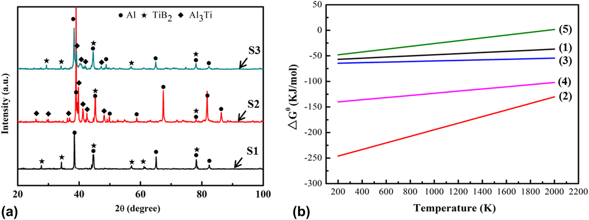
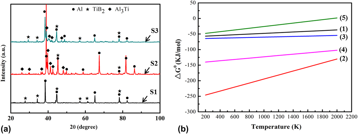
Figure 1(a) shows the XRD patterns of the samples prepared by laser surface alloying of Ti–AlB2 composite powders. It is obviously revealed that the S1 coating consists of TiB2 phase and Al, and no Ti–Al intermetallic compound is observed. However the XRD spectra of S2 and S3 reveal the presence of Al3Ti phase. It suggests that the TiB2 phases are in situ synthesized during laser alloying process, ascribed to the reaction between Ti and AlB2 powders under high laser energy. Therefore, the possible chemical reactions according to the thermodynamic laws can be proposed as followsReference Rapp and Zheng20–Reference Xiao, Gao, Yang, Liu and Li23:
 $$\left[ {{\rm{Ti}}} \right] + \left[ {\rm{B}} \right] \to {\rm{TiB}}\quad ,$$
 $$\left[ {{\rm{Ti}}} \right] + 2\left[ {\rm{B}} \right] \to {\rm{Ti}}{{\rm{B}}_2}\quad ,$$
 $$2\left[ {\rm{B}} \right] + {\rm{Al}} \to {\rm{Al}}{{\rm{B}}_2}\quad ,$$
 $$3{\rm{Al}} + \left[ {{\rm{Ti}}} \right] \to {\rm{A}}{{\rm{l}}_3}{\rm{Ti}}\quad ,$$
 $${\rm{Al}} + \left[ {{\rm{Ti}}} \right] \to {\rm{AlTi}}\quad .$$
(a) XRD patterns of S1, S2, and S3; (b) Gibbs free energies of possible reactions versus temperature.
Generally, ΔG has been used to determine the possibility of a reaction. The free energy of a system at a temperature, T, can be written as follows:
 $$\Delta G = \Delta H - T\Delta S\quad ,$$
where ΔH and ΔS are, respectively, the changes in enthalpy and entropy of two states. Figure 1(b) displays the curves of the Gibbs free energy change versus temperature of the reactions above. It illustrates that all the reactions can proceed spontaneously due to the negative Gibbs free energy change. It is also illustrated that the Gibbs free energy of TiB2 generation is the lowest in all of the above reactions. Consequently, the stability of these products concluded from the thermodynamic reaction can be listed in the order as follows: TiB2 > Al3Ti > AlB2 > TiB > TiAl. Thus, the borides forms in this experiment are all TiB2. In S2 and S3, Ti is relatively redundant in the molten pool; the excessive Ti reacts with Al, which results in the formation of Ti–Al intermetallic compound. Thermodynamically, Al3Ti is preferable to be formed among other Ti–Al compounds, and this suggestion is supported by the XRD results shown in Fig. 1(a).
B. Microstructure evolution
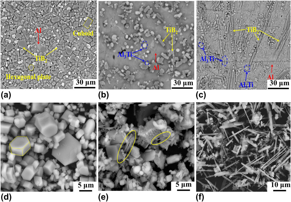
Figure 2 displays the cross-sectional back-scattering electron (BSE) micrographs of the produced coatings. As depicted in Fig. 2(a), the TiB2 particles in S1 are homogeneously distributed in the Al matrix. TiB2 particles mainly exhibit hexagonal plate-like and cuboid morphology. When the molar ratio of Ti and AlB2 increases to 4:1, TiB2 particles basically maintain the original morphology with a small amount of rod-like shape occurring as shown in Fig. 2(b). The as-obtained Al3Ti reinforcements present block-like morphology. Further increasing the Ti contents, a significant change can be seen from the appearance of TiB2 phases. As illustrated in Fig. 2(c), the TiB2 reinforcement particles are mainly in rod-like shape along with block-like Al3Ti. The volume fraction of TiB2 particles of S1, S2, and S3 is 26.01%, 11.76%, and 5.29%, respectively (by using the Image-Pro Plus software, Media Cybernetics, Rockville, Maryland).
Typical cross section BSE images of (a) S1, (b) S2, (c) S3; extracted TiB2 particles from (d) S1, (e) S2, and (f) S3.

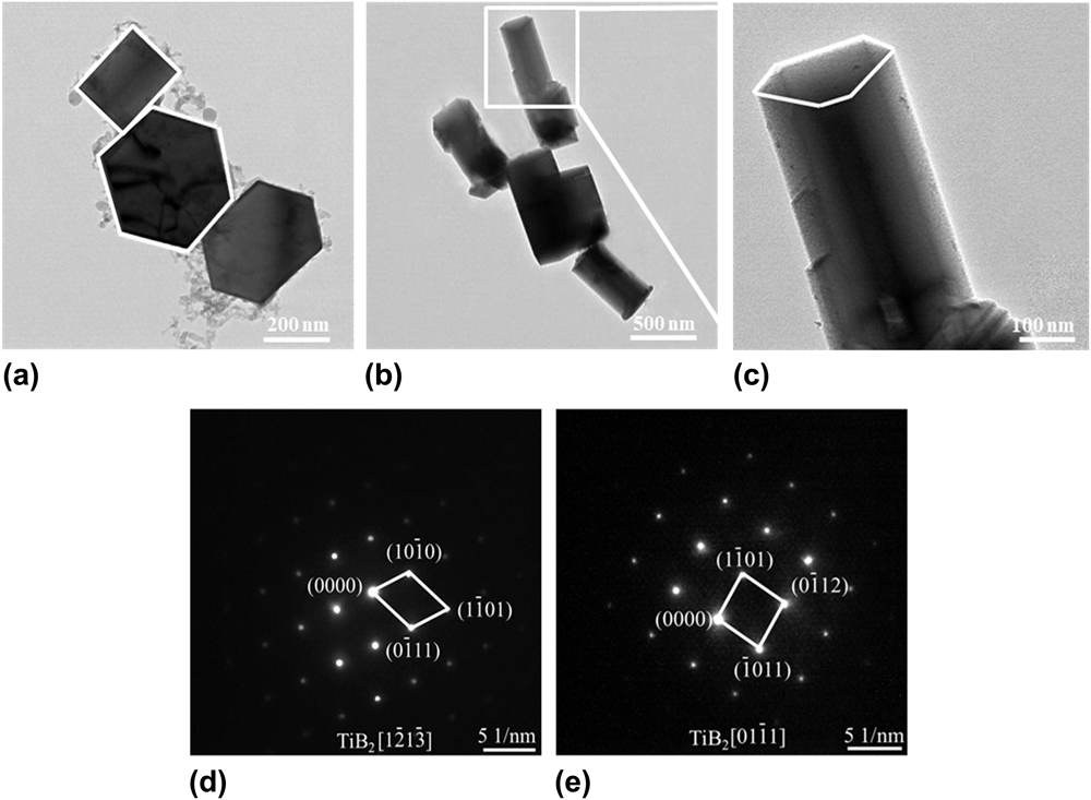
To further study the microstructure and morphology of TiB2 particles, the extraction experiment was conducted on the three samples. Figures 2(d)–2(f) shows the SEM images of TiB2 particles extracted from S1, S2, and S3. As seen in Fig. 2(d), the TiB2 particles extracted from S1 presented cuboid and hexagonal shapes mainly. It is worth noting that some tiny particles with irregularly shaped morphology may be ascribed to the uncompleted growth of TiB2.Reference Niu, Xiao, Kong, Zhang and Chen24 The morphology of extracted TiB2 particles from S2 in Fig. 2(e) displays the similar characteristics to S1, which is in good agreement with the result shown in Figs. 2(a) and 2(b). The morphology of particles extracted from S3 is depicted in Fig. 2(f). It can be found that the TiB2 particles exhibit rod-like shape with some undissolved blocky Al3Ti around them. The morphology and structure have also been confirmed by TEM. The bright-field (BF) images in Fig. 3 present hexagonal plate, cuboid (a) and rod-like (b, c) morphology of TiB2 particles extracted from S1 and S3, respectively. The SAED pattern corresponding to the TiB2 in Figs. 3(a) and 3(c) further confirms the formation of TiB2 reinforcement.
TEM micrograph of the extracted TiB2 showing (a) hexagonal plate and cuboid morphology, (b) and (c) rod-like morphology; (d) and (e) are the SAED corresponding to the TiB2 in (a) and (c), respectively.

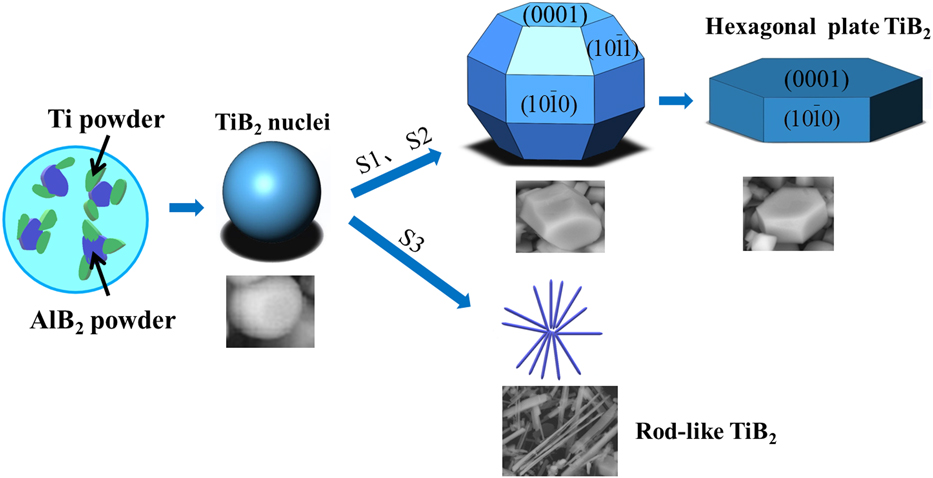
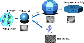
As well known, TiB2 crystal is closely packed by trigonal prisms, and they share the faces with their neighboring prisms.Reference Sahay, Ravichandran and Atri25 Three types of bonding are present in TiB2; the strength of the three bonding is in the sequence of Ti–Ti (metallic) < Ti–B (ionic) < B–B (covalent).Reference Panda and Chandran26 Hamid et al.Reference Hamid, Thibault and Hamar27 have made the calculation for the energy of low-index planes of TiB2; the growth rates of the low-index planes can be listed in the ascending order as: {1211}, {1210}, {1011}, {1010}, {0001}. Therefore, the TiB2 crystal exhibits the equilibrium morphology as hexagonal platelet and has the characteristics of strong anisotropy growth. The microstructure evolution of TiB2 from plate to rod with the increase of Ti contents is partially due to the constraint imposed by the as-formed Al3Ti phase which is growing concurrently with it (Jackson et al.Reference Jackson and Hunt28 have proposed that the second phase’s morphology can be formed as rod-like shape when its volume fraction is relatively small). Another reason may be that the enrichment of Ti atomic concentration in front of the solid/liquid interface of primary TiB2 particles leads to the accelerated growth rate along the [0001] direction. A schematic diagram describing the microstructure evolution of TiB2 particles in Al matrix is shown in Fig. 4.
Schematic diagram for the microstructure evolution of TiB2 particles in Al matrix.

C. Interface structure of TiB2 particles/Al matrix
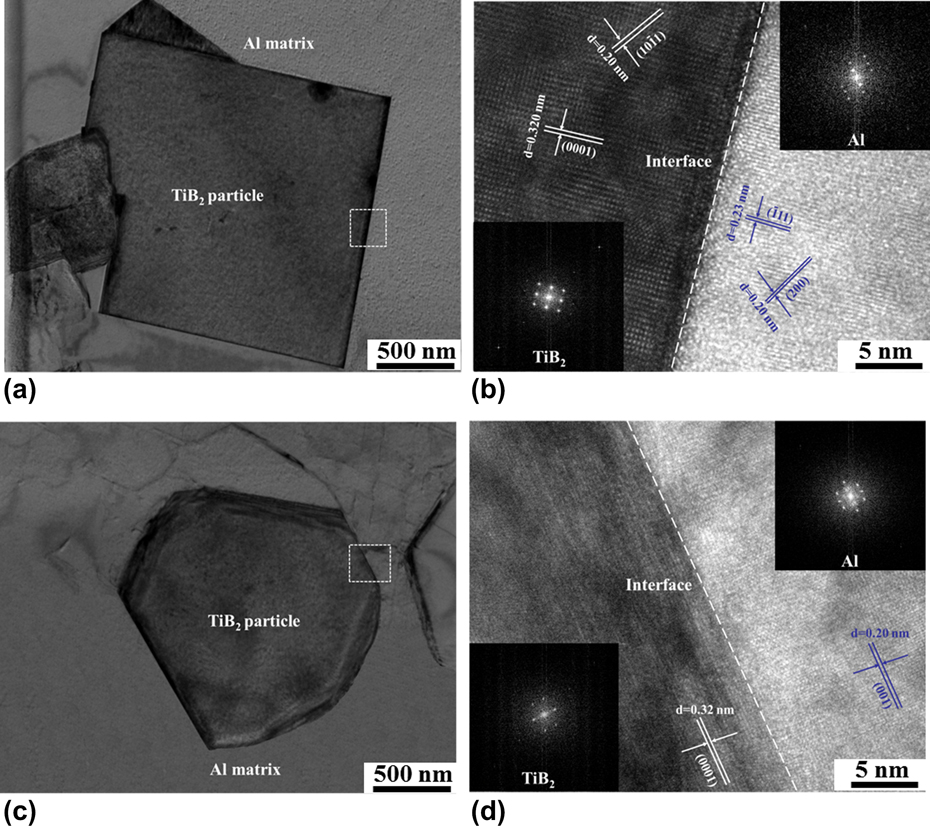
Figure 5 presents the TEM micrograph of S1and S2. The BF images in Figs. 5(a) and 5(c) demonstrate that TiB2 particles are in hexagonal or cubic shape with sharp edges, which is highly consistent with the results shown in Fig. 3. They also reveal a clean interface between Al matrix and TiB2 reinforcements, which is attributed to the in situ fabrication process by laser alloying and good thermodynamic stability of TiB2 in molten Al at high temperatures. It indicates a strong particle–matrix bonding. Dislocation or stacking fault is not found in this study. Figures 5(b) and 5(d) depicts the high-resolution TEM micrograph and fast Fourier transformation (FFT) corresponding to the TiB2/Al interface located in Figs. 5(a) and 5(c).
TEM BF image of (a) S1, (c) S2; HRTEM image of the interface between TiB2 and Al at the white-line box location (b) S1, (d) S2. The insets are the FFT patterns of the TiB2 and Al matrix.

By the investigation of HRTEM, it is observed that the TiB2 particle in S1 combines well with Al matrix and no reactant layer is detected between them. Furthermore, there exists a relationship at the interface between two phases that can be described as  $\left( {10\bar{1}1} \right)$ TiB2 parallel to (200) Al. The HRTEM result of S2 in Fig. 5(d) indicates that TiB2 particle and Al matrix interface is well bonded and no interfacial reactant is formed. The orientation relationship between the aluminum matrix and TiB2 particles can be clarified as
 $\left[ {\bar{2}\bar{1}\bar{1}0} \right]$ TiB2//[110] Al and (0001) TiB2//(001) Al. This orientation relationship is well consistent with the literature.Reference Schaffer, Miller and Dahle29 Based on the Bramfitt’s theoretical model,Reference Bramfitt30 disregistry between the TiB2 particles and aluminum matrix can be calculated by using the formula as shown below:
 $$\delta _{{{\left( {hkl} \right)}_{\rm{n}}}}^{{{\left( {hkl} \right)}_{\rm{s}}}} = {1 \over 3}\sum\limits_{i = 1}^3 {{{\left| {{d_{\left[ {uvw} \right]_{\rm{s}}^i}}.\cos \theta - {d_{\left[ {uvw} \right]_{\rm{n}}^i}}} \right|} \over {{d_{\left[ {uvw} \right]_{\rm{n}}^i}}}}} \times 100\% \quad ,$$
where (hkl)s, [uvw]s, and  ${d_{{{\left[ {uvw} \right]}_{\rm{s}}}}}$ are the low-index plane, low-index directions in (hkl)s, and interatomic distance along [uvw]s of the substrate, respectively; (hkl)n, [uvw]n, and
 ${d_{{{\left[ {uvw} \right]}_{\rm{n}}}}}$ are the low-index plane, low-index directions in [uvw]n, and interatomic distance along [uvw]n of the nucleated reinforcements, respectively; θ is the angle between the substrate and nucleated reinforcements’ low-index directions. TiB2 reinforcement has a hexagonal close-packed crystal structure; the lattice constants of it are a = 0.303 nm and c = 0.322 nm. The crystal structure of the aluminum matrix is face-centered cubic; the lattice constants of it are a = b = c = 0.4049 nm.Reference Villars and Calvert31 The results calculated from the formula illustrate that the disregistry between the TiB2 reinforcement and aluminum matrix in S2 is 13.4% (the maximum value of the disregistry for the reinforcements to serve as an effective nucleus is 15%) (Table I).
Parameters for the disregistry in Eq. (7).

D. Microhardness
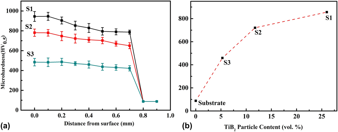
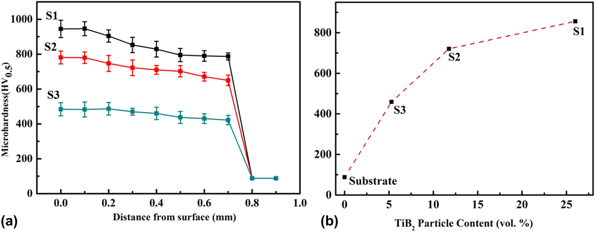
Generally, the microhardness of the laser surface alloying fabricated composites is intimately related to the reinforcement distribution and its content, as well as densification level.Reference AlMangour, Grzesiak and Yang32 Figure 6(a) shows the microhardness distribution of the alloying coating of the three samples along the depth direction with the different Ti to AlB2 molar ratio. It can be seen that the hardness of all the three specimens improves significantly compared with the aluminum substrate (approximately 88 HV0.5). The coating of S1 displays highest hardness value compared with S2 and S3, as shown in Fig. 6. The average microhardness of S1, S2, and S3 is 856.1 HV, 720.4 HV, and 459.1 HV, respectively. It is generally observed that the hardness decreases with increasing Ti contents. The main reason for the decrease in the microhardness may be that the excessive Ti leads to the decrease in TiB2 reinforcements as seen in Fig. 6(b). Above all, the hardness improvement of all the three coatings mentioned above is ascribed to the dispersion strengthening of in situ synthesized TiB2 reinforcements homogeneously distributed in the Al matrix, as well as the refined and compact microstructure formed by the rapid heating and solidification process during laser surface alloying.
(a) Microhardness distribution across the cross section of the samples; (b) the average microhardness of the coating across different TiB2 particle contents.
E. Wear property
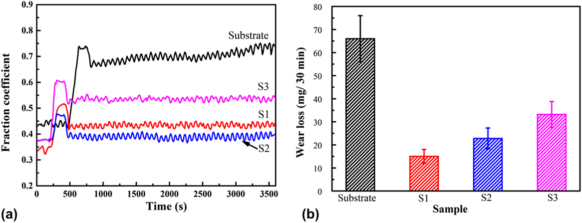
The friction coefficients and the wear rates of the coating and substrate are shown as a function of friction time in Figs. 7(a) and 7(b), respectively. It can be observed from Fig. 7 that S1, S2, and S3 have lower friction coefficients, lower wear rates, and higher friction stabilities in comparison with the aluminum substrate. Figure 7(a) shows that the friction coefficient of AA6061 substrate increases with time and the average friction coefficient is about 0.85. The friction coefficients of the as-obtained samples are relatively high at the beginning and then reduce gradually. It can be explained by the high surface roughness in the beginning combined with the inhomogeneous distribution of TiB2 particles of the samples, while with increasing friction time, solid film consisting of TiB2 particles will form at the contact surface. The average friction coefficients of S1, S2, and S3 are about 0.5, 0.42, and 0.65, respectively. It depicts an obvious decrease in friction coefficient from 0.85 to 0.42 by the in situ synthesized TiB2 reinforcements. It also suggests that S2 exhibits the lowest friction coefficient as compared with S1 and S3. It may be explained by the high hardness of S2 combined with the good wettability between the matrix alloy and reinforcements. The existence of Al3Ti phase in S2 may also enhance the metallurgical bonding between the reinforcements and matrix.
(a) The friction coefficient and (b) wear loss of the substrate and as-obtained samples as a function of friction time.
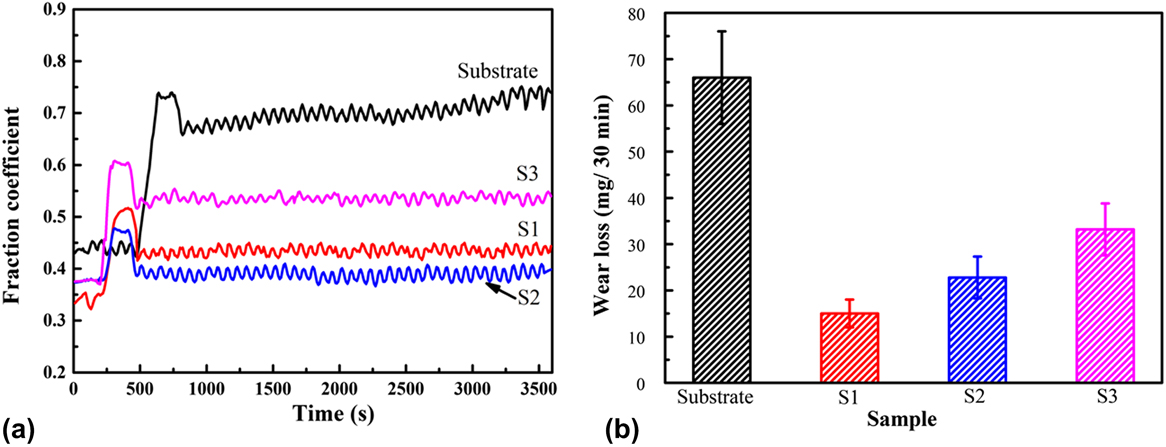
According to the results displayed in Fig. 7(b), the wear rate of the substrate is 66.0 mg every 30 min and that of S1, S2, and S3 is 15.0 mg, 22.8 mg, and 33.2 mg, respectively, indicating a great improvement in wear resistance than the substrate. Furthermore, it is observed that S1 shows lower wear rate than the other two samples.
It is generally known thatReference Tjong and Lau33 the wear property is in relation to the testing conditions (loading force, sliding distance, loading speed), contact variables (with or without lubricant), and materials properties (microhardness, strength, and toughness). RabinowiczReference Rabinowicz and Tanner34 has proposed a formula that can be used to reveal the relationship between the volume of abrasion loss and the hardness of materials, as well as the testing conditions for abrasive wear. The specific calculation formula is listed as follows:
 $$V = {{kPL} / H}\quad ,$$
where V, P, and L are the volume of abrasion loss, the applied loading force, and the sliding distance, respectively. H is the microhardness of the sample, and k is the coefficient of wear. The equation depicts that the volume of abrasion loss of a certain composite is correlated reciprocally with its microhardness. Therefore, the values of k, P, and L are the same of all the three samples in this study and the wear rates increase as a function of the volume ratio of TiB2 in the composites. The hardness of S3 is lower than that of S1 and S2 because of lower TiB2 content, thus reducing its wear resistance.
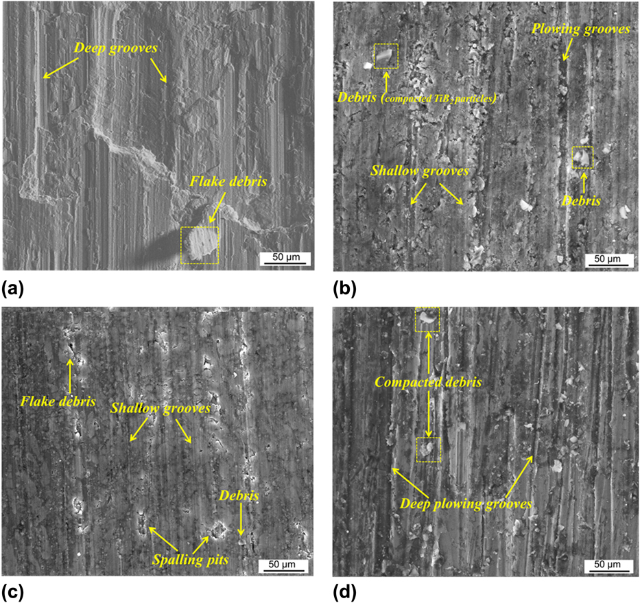
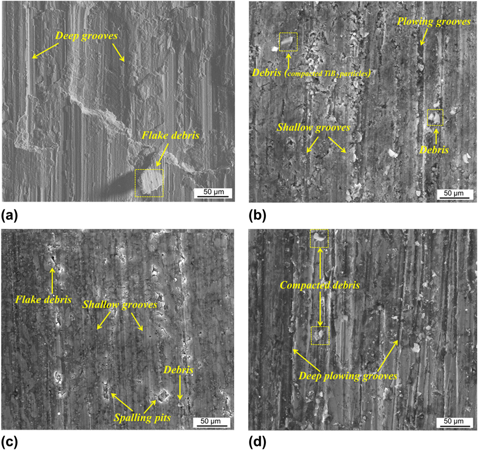
SEM analysis was conducted to investigate the morphologies of the worn surface of the as-obtained samples and substrate. The examination of the as-obtained substrate worn surface reveals large amount of deep and wide plowing grooves running parallel to one another in the sliding direction. This can be attributed to the absence of hard reinforcements, which cause the microplowing of the substrate during wear. The worn surface morphologies of TiB2-reinforced samples are characterized by less and shallower grooves compared with the substrate as shown in Figs. 8(b)–8(d). The surface morphology of S3 clearly seemed to be abraded more seriously than S1 and S2, which is in accordance with the results of wear rates shown in Fig. 7. Besides, some spalling pits and debris are observed on the worn surface of the as-obtained samples. The reinforcement debris on the worn surface was pulled out on the surface and spalled off by the microcutting action. The spalling pits and debris can act as load-bearing particles. This suggests that the primary wear mechanism of the composites is abrasive wear. A more detailed description of a similar mechanism is well documented in B4C-particles-reinforced Al-based MMCs by Ipek.Reference Ipek35
Worn surface morphologies of (a) the substrate, (b) S1, (c) S2, and (d) S3.
IV. CONCLUSION
The following conclusions can be drawn from the present study on microstructure evolution and properties of in situ synthesized TiB2-reinforced aluminum alloy by laser surface alloying.
(1) The XRD and TEM analyses confirm that the in situ TiB2/AA6061 composites have been synthesized successfully by laser surface alloying and hence it can be adapted in manufacturing easily.
(2) By adjusting the ratio of Ti and AlB2 alloying powders, TiB2-reinforcing particulates can be produced in controllable amounts and morphology. Ti contents played a very important role in controlling the phase evolution of TiB2 particles from hexagonal plates to rods.
(3) The results of TEM revealed that the as-obtained composites have a well-bonded interface between the TiB2 reinforcements and aluminum matrix.
(4) The influence of TiB2 particles on wear property of Al-based MMCs and the wear mechanism was also discussed in detail.
ACKNOWLEDGMENTS
The author is grateful for the financial support from the National Key Technologies R&D Program of China.