1. Introduction
Individual life quality is directly dependent on the capacity of performing voluntary tasks safely and independently. Any degeneration of these capacities leads to medical intervention followed by rehabilitation sessions to restore the initial motor ability [Reference Babaiasl, Mahdioun, Jaryani and Yazdani1]. With an increasing need for functional re-education [Reference Maciejasz, Eschweiler, Gerlach-Hahn, Jansen-Troy and Leonhardt2], the duration of the rehabilitation procedures goes up to several weeks [Reference Guiet and Claire3]. Thus, providing sophisticated tools to assist the therapists’ tasks and to evaluate the rehabilitation process become essential. A variety of robotic devices have been developed for these purposes [Reference Gassert and Dietz4–Reference Qassim and Hasan6]. Several criteria must be considered while designing this kind of human–robot devices [Reference Xiong and Diao7]. One of the crucial ones is the user’s safety [Reference Carbone, Gherman, Ulinici, Vaida and Pisla8]. Both the therapist and the patient must be kept out of danger during the rehabilitation process.
One of the recent devices used for rehabilitation purposes is the cable-driven parallel robot (CDPR) [Reference Tang9]. It is a mechanism formed by a moving platform connected to a fixed base via cables wound around actuated pulleys [Reference Deng, Bai, Long, Guan, Chen, Hou and Duan10]. By acting on the length of each wire, the poses taken by the end-effector are controlled. This type of mechanism has multiple advantages compared to serial and classic parallel manipulators [Reference Qian, Zi, Shang and Xu11] which make them convenient also for other applications (industrial applications [Reference Andreas, Hendrik and Werner12], sport simulation [Reference Laura, Rauter, Wyss, von Zitzewitz and Riener13, Reference Georg, Joachim, D. and Alexander14]). They can provide a large translational workspace, and their lightweight moving parts offer them a low inertia and a high velocity. Despite these characteristics, CDPRs cannot provide a large rotational workspace due to collisions between their moving parts [Reference Blanchet and Merlet15]. Some methods addressing the extension of the allowable range of rotation have been proposed in the literature. In ref. [Reference Reichenbach, Tempel, Verl and Pott16], the authors proposed the design of a planar CDPR with an unlimited rotation by using two mobile platforms. The relative positioning between the two end-effectors creates the needed rotation between them. This method becomes more complex in the case of mechanisms with three rotational degrees of freedom (dof) since adding multiple mobile platforms makes the workspace more cluttered. A reconfigurable CDPR has been proposed in ref. [Reference Gagliardini, Gouttefarde and Caro17]. It is based on dividing a complex workspace into parts, each one having a corresponding exit point position. To switch from one part to the other, the execution of the task must be interrupted to configure the next predefined exit points location. In ref. [Reference Zhao and Gao18], the authors proposed the design of a cable-driven hyper-redundant manipulator allowing to reach an extended task workspace. This mechanism is composed of several serial links controlled by antagonistic cables and connected by Hooke joints. Another method was proposed in ref. [Reference Faschinger, von Zitzewitz and Pernkopf19] to extend the CDPR workspace robot using actuated deflection units for cable routing [Reference Joachim, Lisa and Tobias20].
Various studies have been conducted in the literature addressing the optimal design of CDPRs. Numerous criteria can be considered such as the maximal cable tension and the velocity minimization [Reference Hanafie, Nurahmi, Caro and Pramujati21], the dexterity and the rigidity maximization [Reference Abdolshah, Zanotto, Rosati and Agrawal22], and the workspace area maximization [Reference Fattah, Agrawal and S.23]. In order to guarantee a secure use of this type of robot, the potential collisions between its moving parts must be avoided. Several algorithms where the cables are considered as straight lines and the human body as a geometrical volume have been proposed in the literature to deal with this issue [Reference Hamida, Laribi, Mlika, Romdhane, Zeghloul and Carbone24, Reference Zitzewitz, Rauter, Steiner, Brunschweiler and Riener25]. A validation of the algorithm proposed in ref. [Reference Zitzewitz, Rauter, Steiner, Brunschweiler and Riener25] was performed experimentally with a cable robot developed to simulate sport activities.
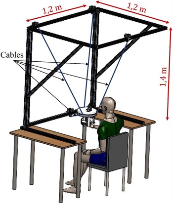
The problem of covering a large rotational workspace with the smallest structure using a CDPR is addressed in this paper. The wide rotation amplitudes are obtained by analyzing a subject’s hand motion along three activities of daily living (ADLs) prescribed by therapists. The robot aimed by this study allows to assist the patient’s upper limb along these three exercises during rehabilitation sessions. Based on the identified task workspace, a formulation of an optimization problem, taking mainly the patient’s safety into consideration, is firstly proposed. Afterward, the solution of a reconfigurable robot covering the same rotational workspace but with a smaller structure is suggested. Finally, in the aim of finding a robot size adequate with rehabilitation applications, the solution of a hybrid robot is proposed. It consists of designing an actuated orthosis, where to attach the patient’s hand. This orthosis will assist the hand orientations. As to the latter’s translations, they will be supported by four cables.
The paper is organized as follows: Section 2 details the experimental setup used to identify the task workspace. Section 3 introduces the robot model notations and formulates the optimization problem aiming to select the smallest robot structure while respecting a set of constraints. In Section 4, a reconfiguration aspect is added to the CDPR in the aim of reducing its size. Section 5 proposes the adopted solution of the hybrid robot, and the last section concludes the paper.
2. The prescribed workspace analysis
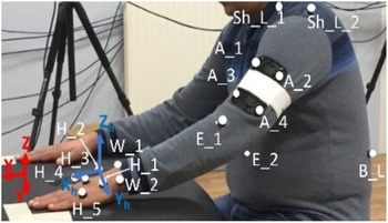
This study aims to design a CDPR for upper limb rehabilitation. This robot allows assisting the patient’s affected member along three prescribed ADLs, selected with the help of occupational therapists. These exercises consist of moving the patient’s hand from an initial position to touch either his mouth, his head, or his shoulder and then returning to the starting position. Five volunteers (two left-handed and three right-handed) have participated in the current study. They performed five cycles of each movement. A Qualisys motion capture system [Reference Laribi and Zeghloul."26] was set up to track their gestures and collect the needed measurements to characterize each movement. This system is composed of a set of infrared cameras and passive reflective markers. The collected data, namely the position in the 3D space of each marker, were then recorded in real time using “QTM” (Qualisys Track Manager) software. Each participant performs the prescribed exercises with its dominant upper limb on which the passive reflective markers are fixed, as shown in Fig. 1. The experimental setup is presented with more details in our previous work [Reference Ennaiem, Chaker, Arévalo, Laribi, Bennour, Mlika, Romdhane and Zeghloul27]. A local frame (
 $\textbf{X}_{\textbf{h}}, \textbf{Y}_{\textbf{h}}, \textbf{Z}_{\textbf{h}})$
was attached to the participant’s hand. It is defined by three markers: H_2 as origin, the vector H_2H_4 as the
 $\textbf{X}\_ \textbf{h}$
axis, the vector H_2H_1 as the
 $\textbf{Y}\_ \textbf{h}$
axis, and
 $\textbf{Z}\_ \textbf{h}$
axis is perpendicular to
 $\textbf{X}\_ \textbf{h} \textbf{Y}\_ \textbf{h}$
plan. Based on this local frame, the software computes its orientation, with respect to a global frame
 $(\textbf{X},\textbf{Y},\textbf{Z})$
attached to the table, using the Euler angles
 $\psi,\theta,$
and
 $\phi$
corresponding to the
 $\textbf{Z},\textbf{X},\textbf{Z}$
convention.
Location of the passive reflective markers on the subject.

The robot aimed by this study is intended for an end-effector rehabilitation procedure. Only the hand and the wrist of the subject will be attached to the mobile platform. The movement of the latter will assist the subject in replicating the selected tasks. During the motion capture procedure, the hand trajectory is tracked utilizing the marker “H_3”. The markers attached to the rest of the patient’s body will help avoiding the potential collisions between the body and the cables. This constraint aiming to guarantee the user safety is detailed in Section 3.3.4.
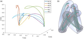
An intra-subject and an inter-subject variability analysis were carried out in ref. [Reference Ennaiem, Chaker, Arévalo, Laribi, Bennour, Mlika, Romdhane and Zeghloul28]. The analysis compared the subjects’ gestures along the exercises to select a single prescribed workspace that fits with a maximum number of patients. The survey showed no unique movement pattern. Participants perform the task differently despite their similar anthropomorphic parameters. The adopted robot-prescribed workspace combines the volume of six tori portions enclosing, each, one trajectory. Figure 2(a) shows one cycle of each movement recorded for one left-handed and one right-handed participant. The overall task workspace and all the recorded trajectories are illustrated in Fig. 2(b).
(a) One cycle of each trajectory, “M1,” “M2,” and “M3” refer to the “hand–mouth,” the “hand–head,” and the “hand–shoulder” movements, respectively. “R” and “L” denote the right-handed and the left-handed subject, respectively. (b) The translational task workspace.

Regarding the rotational workspace, the hand orientations (
 $\psi,\theta,$
 $\phi$
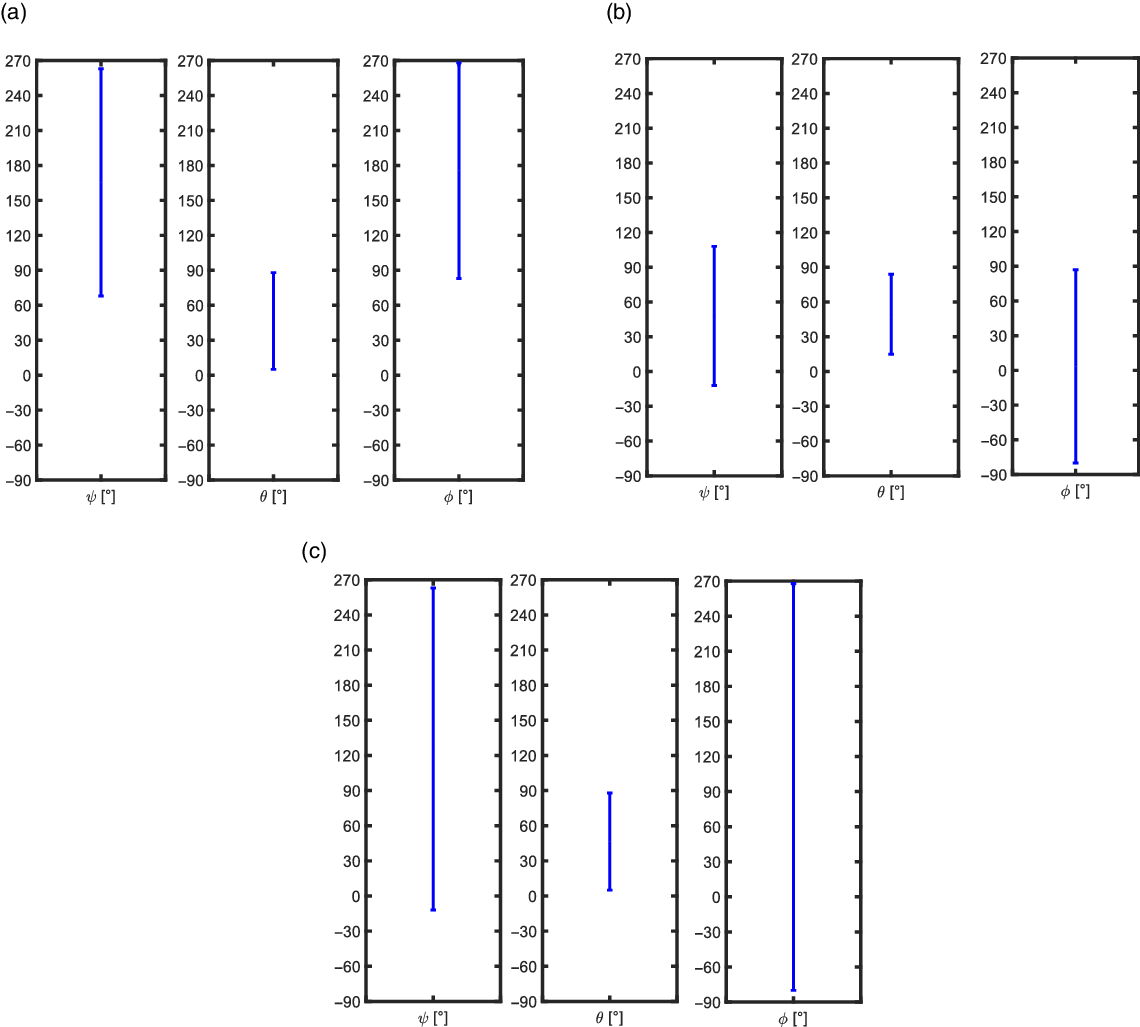
) along the three selected tasks are compared for the five cycles of each participant. The largest range of variation of each rotation angle, formed by the interval between its minimum and maximum values, is considered as the rotational workspace as illustrated in Fig. 3.
The largest range of variation of Euler rotation angles computed for (a) the left-handed subjects, (b) the right-handed subjects, and (c) the overall movements.

3. Optimization problem formulation
3.1. The robot modeling
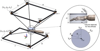
A 6-dof CDPR with seven cables is considered in this paper. Each cable
 $i$
is wound on an actuated pulley called
 $\mathcal{P}_{i}$
, then, it passes through a rotating and small size guide pulley
 $\mathcal{P}_{i}^{\prime}$
and finally attached to the robot end-effector at the anchor point
 $B_{i}$
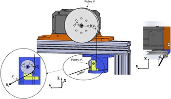
as illustrated in Fig. 4 The mobile platform is considered as a flat cylinder of height equal to
 $h$
.
Geometric representation of the CDPR’s parameters.

The orientation of the pulleys
 $\mathcal{P}_{i\in [1..7]}^{\prime}$
changes according to the pose of the end-effector. Thus, the location of the cable exit points
 $A_{i}$
varies also. For the sake of simplicity, some authors consider these points to be fixed along the prescribed trajectory [Reference Gagliardini, Caro, Gouttefarde, Wenger and Girin29, Reference Abdolshah, Zanotto, Rosati and Agrawal30]. This assumption leads to inaccuracy while controlling the end-effector poses caused by slack or over-tensioned cables. In the aim of considering a realistic robot design, the variation of the cable exit points position is taken into consideration and the points
 $\mathcal{T}_{i}$
are used instead for the robot modeling (see Fig. 4). Since the cables are tangent to the pulley
 $\mathcal{P}_{i}^{\prime}$
, the coordinates of the points
 $\mathcal{T}_{i}$
remain constant for all the poses of the end-effector.
The robot architecture can be characterized using a set of 18 parameters, as independent design variables, represented in Fig. 5, that is,
 $x_{\textrm{u}},y_{\textrm{u}},z_{\textrm{u}},x_{l},y_{l}$
, and
 $z_{l}$
describe the location of the robot with respect to the global frame
 $\mathfrak{R}_{G}$
and
 $a, b, c,$
and
 $d$
define the structure size.
 $R_{pl}$
and
 $\theta _{i}$
give the coordinates of the points
 $B_{i}$
(the anchor points) in the local frame
 $\mathfrak{R}_{L}(\textbf{X}_{\textbf{L}}, \textbf{Y}_{\textbf{L}}, \textbf{Z}_{\textbf{L}})$
attached to the end-effector. These parameters form the design vector
 $\textbf{I}$
, expressed as given in Eq. (1).
 \begin{equation} \textbf{I}=\left[x_{u},y_{u},z_{u},a, b, c, d, x_{l},y_{l},z_{l},R_{pl}, \theta _{i}\left(i=1..7\right)\right] \end{equation}
Geometric representation of the CDPR design vector parameters.

The parameters of the design vector
 $\textbf{I}$
are used to define the coordinates of the points
 $\mathcal{T}_{i}$
in the global frame
 $\mathfrak{R}_{G}$
and the coordinates of the anchor points
 $B_{i}$
in the local frame
 $\mathfrak{R}_{L}$
, gathered in the matrices
 $\boldsymbol{\mathcal{T}}$
and
 $\textbf{B}$
, respectively, as follows:
 \begin{equation} \boldsymbol{\mathcal{T}}=\left[\begin{array}{c@{\quad}c@{\quad}c} x_{u} & y_{u} & z_{u}\\ x_{u} & y_{u}-b & z_{u}\\ \\[-7pt] x_{u}-a & y_{u}-b & z_{u}\\ \\[-7pt] x_{u}-a & y_{u} & z_{u}\\ \\[-7pt] x_{l}-c & y_{l} & z_{l}\\ \\[-7pt] x_{l} & y_{l}-d/2 & z_{l}\\ \\[-7pt] x_{l}-c & y_{l}-d & z_{l} \end{array}\right] \end{equation}
 \begin{equation} \textbf{B}=\begin{cases} \left[\begin{array}{c@{\quad}c@{\quad}c} R_{pl}\cos \theta _{i} & R_{pl}\sin \theta _{i} & h \end{array}\right]^{T}, i=1..4\\ \\[-9pt]\left[\begin{array}{c@{\quad}c@{\quad}c} R_{pl}\cos \theta _{i} & R_{pl}\sin \theta _{i} & 0 \end{array}\right]^{T}, i=5..7 \end{cases} \end{equation}
The Jacobian matrix can be expressed as given in Eq. (4), where
 $\textbf{R}$
is the rotation matrix between
 $\mathfrak{R}_{L}$
and
 $\mathfrak{R}_{G}$
, and
 $\textbf{n}_{\textrm{i}}$
, the unit vector along the
 $i^{th}$
cable, is given by Eq. (5).
 \begin{equation} \textbf{J}=\left[\begin{array}{c} \textbf{n}_{\textrm{i}}\\ \textbf{R}\textbf{B}_{\textbf{i}}\wedge \textbf{n}_{\textrm{i}} \end{array}\right]^{\textrm{T}}, i=1..7 \end{equation}
 \begin{equation} \textbf{n}_{\textbf{i}}=\frac{\textbf{B}_{\textbf{i}}\textbf{A}_{\textbf{i}}}{\|\textbf{B}_{\textbf{i}}\textbf{A}_{\textbf{i}}\|}=\frac{1}{L_i}\left[\begin{array}{c}\sin(\varphi_{i}+\gamma_{i})\cos(\beta_{i})\\ \\[-9pt] \sin(\varphi_{i}+\gamma_{i})\sin(\beta_{i})\\ \\[-9pt] \cos(\varphi_{i}+\gamma_{i}) \end{array}\right], i=1..7 \end{equation}
 \begin{equation} L_{i}=\sqrt{\left\| \textbf{B}_{\textbf{i}}\boldsymbol{\mathcal{C}}_{\textbf{i}}^{\prime}\right\| ^{2}-{R_{\mathcal{P}_{i}^{\prime}}}^{2}}, i=1..7 \end{equation}
 \begin{equation} \gamma _{i}=\tan ^{-1} \left(\frac{R_{\mathcal{P}_{i}^{\prime}}}{L_{i}}\right), i=1..7 \end{equation}
 \begin{equation} \varphi _{i}=\cos ^{-1} \left(\frac{\textbf{B}_{\textbf{i}}\boldsymbol{\mathcal{C}}_{\textbf{i}}^{\prime}\cdot \textbf{Z}}{\left\| \textbf{B}_{\textbf{i}}\boldsymbol{\mathcal{C}}_{\textbf{i}}^{\prime}\right\| }\right), i=1..7 \end{equation}
 \begin{equation} \beta _{i}=\cos ^{-1} \left(\frac{\textbf{n}_{\textbf{i}}\cdot \textbf{X}}{\left\| \textbf{n}_{\textbf{i}}\right\| }\right), i=1..7 \end{equation}
where
 $L_{i}$
is the length of the
 $i^{th}$
cable,
 $\boldsymbol{\mathcal{C}}_{\textbf{i}}^{\prime}$
is the vector containing the coordinates of the point,
 $\mathcal{C}_{\textrm{i}}^{\prime}$
is the center of the pulley
 $\mathcal{P}_{i}^{\prime}$
, and
 $R_{\mathcal{P}_{i}^{\prime}}$
is the radius of
 $\mathcal{P}_{i}^{\prime}$
.
The cable tensions can then be expressed as follows:
 \begin{equation} \textbf{T}_{\textbf{c}}=\textbf{T}_{{\textbf{c}_{\textbf{p}}}}+\textbf{T}_{{\textbf{c}_{\textbf{h}}}}=-\left(\textbf{J}^{\textrm{T}}\right)^{+}{\textbf{F}_{\textbf{ext}}}_{/\textbf{EE}}+\lambda \textrm{Null}\left(\textbf{J}^{\textrm{T}}\right) \end{equation}
where
 $\textbf{T}_{{\textbf{c}_{\textbf{p}}}}=-\left(\textbf{J}^{\textrm{T}}\right)^{+}{\textbf{F}_{\textbf{ext}}}_{/\textbf{EE}}$
is the particular solution,
 $\textbf{T}_{{\textbf{c}_{\textbf{h}}}}=\lambda \textrm{Null}(\textbf{J}^{\textrm{T}})$
is the homogenous solution,
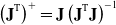 $\left(\textbf{J}^{\textrm{T}}\right)^{+}=\textbf{J}\left(\textbf{J}^{\textrm{T}}\textbf{J}\right)^{-1}$
is the Moore–Penrose pseudo-inverse of the wench matrix
 $\textbf{J}^{\textrm{T}}$
,
 ${\textbf{F}_{\textbf{ext}}}_{/\textbf{EE}}$
is the external forces vector applied to the moving platform, and
 $\lambda$
is a scalar, added to keep the cable tensions positive [Reference Williams, Gallina and Vadia31], computed as given in Eq. (11), where
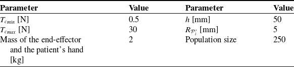
 ${T_{c}}_{min}$
is a predefined lower boundary of the cable tension
 $\textbf{T}_{\textbf{c}}$
(see Table I).
 \begin{equation} \lambda =\max _{i=1..7} \left[\frac{{T_{c}}_{min}-\textrm{T}_{{\textrm{c}_{\textrm{p}}}}\left(i\right)}{\text{Null }\left(\textbf{J}^{\textrm{T}}\right)\left(i\right)}\right] \end{equation}
Optimization parameters.

The robot proposed in this study is intended for passive rehabilitation. This mode of rehabilitation is prescribed by physiotherapists during the initial phase of the therapy, where the patient is unable to move autonomously his upper limb. Thus, the external forces vector
 ${\textbf{F}_{\textbf{ext}}}_{/\textbf{EE}}$
, given by Eq. (12), is formed only by the gravity force. The forces applied by the patient are not considered.
 \begin{equation} {\textbf{F}_{\textbf{ext}}}_{/\textbf{EE}}=\left[\begin{array}{c@{\quad}c@{\quad}c@{\quad}c@{\quad}c@{\quad}c} 0 & 0 & -m_{T}\textbf{g} & 0 & 0 & 0 \end{array}\right]^{\textrm{T}} \end{equation}
where
 $\textbf{g}$
is the gravitational acceleration and
 $m_{T}$
is the total weight supported by the cables (mass of the end-effector and the patient’s hand).
3.2. Optimization criterion
The size of the robot structure should be adequate with the target application. For psychological reasons, rehabilitation robots should also be ergonomic and have a friendly looking design. Both the therapist and the patients need to feel comfortable while manipulating them. Thus, finding a compromise between the large task workspace and the compact size of the structure forms the robot optimization criteria. It is formulated using the parameter
 $\mathcal{S}$
as given by Eq. (13).
 $\mathcal{S}$
measures the normalized distance between the center of mass of the end-effector and the corrected exit points
 $\mathcal{T}_{i}$
(the tangent point between the guide pulley
 $\mathcal{P}_{i}^{\prime}$
and its rotation axe (see Fig. 4)) computed for each end-effector position along the prescribed workspace.
 \begin{equation} \mathcal{S}=\frac{\sum _{j=1}^{n}\mathcal{S}\left(j\right)}{n\cdot \max _{j=1..n} \mathcal{S}\left(j\right)} \end{equation}
 \begin{equation} \mathcal{S}(j)=\sum_{i=1}^{7}\sqrt{\left(x(j)-x_{\mathcal{T}_{i}}\right)^{2}+\left(y(j)-y_{\mathcal{T}_{i}}\right)^{2}+\left(z(j)-z_{\mathcal{T}_{i}}\right)^{2}} \end{equation}
where
 $n$
is the number of positions composing the workspace (the task workspace represented in Fig. 2(b) is composed of 499 points, thus
 $n=499),$
 $x(j), y(j),$
and
 $z(j)$
represent the end-effector location in the global frame
 $\mathfrak{R}_{G}$
at the position
 $j$
, and
 $x_{{\mathcal{T}_{i}}}$
,
 $y_{{\mathcal{T}_{i}}},$
and
 $z_{{\mathcal{T}_{i}}}$
are the coordinates of the point
 $\mathcal{T}_{i}.$
3.3. Optimization constraints
A set of constraints was chosen to guarantee the proper functioning of the robot. They are summed up in reducing energy consumption and ensuring patients’ safety.
3.3.1. Cable tensions boundaries
The cable tensions must have a minimum positive value to avoid slack cables. Also, it should not exceed the mechanical capacity of the actuators. In other words,
 $T_{ci}$
have to be bounded between a maximum and a minimum limit. This constraint is formulated as follows:
 \begin{equation} 0\lt {T_{c}}_{min}\leq T_{ci}\left(j\right)\leq {T_{c}}_{max}, i=1..7, j=1..n \end{equation}
3.3.2. Cable–cable collisions
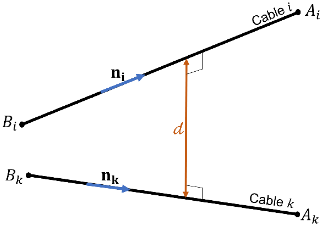
Some orientations of the end-effector may lead to interference between cables, which will cause uncontrollable movements of the mobile platform transmitted to the patient’s hand. The potential collisions between cables are integrated as a problem constraint to guarantee the patient’s safety and the end-effector movement accuracy. The shortest distance between cables,
 ${d},$
considered as rigid segments, is computed (see Fig. 6).
 ${d}$
must remain strictly positive for each pose of the end-effector. This constraint is expressed in Eq. (16).
 \begin{equation} {d}=\frac{\left\| \textbf{n}_{\textbf{i}},\textbf{n}_{\textbf{k}},\textbf{B}_{\textbf{i}}\textbf{B}_{\textbf{k}}\right\| }{\left\| \textbf{n}_{\textbf{i}}\times \textbf{n}_{\textbf{k}}\right\| }\gt 0,\quad i=1..7,\quad k=1..7,\quad i\neq k \end{equation}
where
 $\textbf{n}_{\textbf{i}}$
,
 $\textbf{n}_{\textbf{k}}$
,
 $B_{i},$
and
 $B_{k}$
are the unit vectors and the anchor points of the cables
 $i$
and
 $k$
, respectively.
Cable–cable collisions.

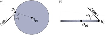
Cable–mobile platform collisions.

3.3.3. Cable–mobile platform collisions
Another type of collision can be caused by the rotations of the end-effector, which is the interference between the cables and the end-effector. To avoid this type of collision, the angle
 $\alpha _{i}$
between the
 $i^{th}$
cable and
 $\textbf{O}_{\textbf{pl}}\textbf{B}_{\textbf{i}}$
is calculated for each position of the mobile platform.
 $\alpha _{i}$
must remain greater than a limit value
 $\alpha _{lim}$
. This constraint is expressed as follows:
 \begin{equation} {\unicode{x03B1} _{\textrm{i}}}=\cos ^{-1} \left(\frac{\textbf{n}_{\textbf{i}}\cdot \textbf{O}_{\textbf{pl}}\textbf{B}_{\textbf{i}}}{\left\| \textbf{O}_{\textbf{pl}}\textbf{B}_{\textbf{i}}\right\| }\right)\gt \alpha _{lim},\quad i=1..7 \end{equation}
 \begin{align} \alpha _{lim}=\begin{cases} 2^{\circ}\ if \text{the cable }i\ \text{and the platform are not on the same plane}\left(\textrm{Fig}.7\textrm{b}\right)\\ \\[-8pt]90^{\circ}\ \text{if the cable }i\ \text{and the platform are on the same plane}\left(\textrm{Fig}.7\textrm{a}\right) \end{cases} \end{align}
3.3.4. Cable–patient collisions
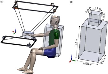
Human–robot interaction devices require an intense precautional analysis during the designing phase to ensure the user’s safety. This security issue has been investigated in several works. In ref. [Reference Carbone, Gherman, Ulinici, Vaida and Pisla8], the authors explained the main factors affecting the patient’s safety during his upper limb rehabilitation such as the acceptable robot speed, forces, or torques adequate with the human motion capacity. When it comes to CDPRs, a supplementary issue arises which is the potential collisions between the wires and the patient’s body (see Fig. 8a). In ref. [Reference Hamida, Laribi, Mlika, Romdhane, Zeghloul and Carbone24], the authors introduced this matter as an optimization criterion. Their work consists of discretizing the cables into several points and then maximizing the distance between each point and a cylinder volume around the patient’s shoulders. In this paper, the cable–patient collision is considered as a constraint. A representative volume of the patient’s head and trunk is created based on the average human dimensions [32] (see Fig. 8(b)). For each pose of the end-effector, the intersection between this volume and each cable is computed and the solution with no interferences will be maintained. Regarding the collisions with the patient’s upper limb, his arm and forearm are tracked during all the tasks through the attached markers. Thus, this collision is avoided as well.
Cable–patient collisions (a) the patient position relative to the robot structure and (b) the volume surrounding the patient’s trunk and head.

3.4. Problem formulation
The optimization presented in this paper aims to select the smallest structure of a CDPR allowing to assist the patient’s upper member along the prescribed workspace. The problem constraints are handled using the penalty formulation, whose functions
 ${j}_{i\in [1..4]}$
are given by Eqs. (22)–(25). The optimization problem formulation, where
 $\mathfrak{j}$
is a large scalar, is expressed as follows:
 \begin{equation} \min \left(\mathcal{J}\left(\textbf{I}\right)\right) \end{equation}
 \begin{equation} \left(\mathcal{J}\left(\textbf{I}\right)\right)=\mathcal{S}+j_{1}+j_{2}+j_{3}+j_{4} \end{equation}
 \begin{equation} \mathcal{S}\left(j\right)=\sum _{i=1}^{7}\sqrt{\left(x\left(j\right)-{x_{{\mathcal{T}_{i}}}}\right)^{2}+\left(y\left(j\right)-{y_{{\mathcal{T}_{i}}}}\right)^{2}+\left(z\left(j\right)-{z_{{\mathcal{T}_{i}}}}\right)^{2}} \end{equation}
 \begin{align} {j}_{1}=\begin{cases} 0 & \textrm{if}\ 0\lt {T_{c}}_{min}\leq T_{ci}\left(j\right)\leq {T_{c}}_{max},\ i=1..7, j=1..n \\ \\[-9pt] \mathfrak{j} & \text{otherwise} \end{cases} \end{align}
 \begin{align} {j}_{2}=\begin{cases} 0 & \textrm{if}\ {d}\gt 0\\ \\[-9pt] \mathfrak{j} & \text{otherwise} \end{cases} \end{align}
 \begin{align} {j}_{3}=\begin{cases} 0 & \textrm{if}\ \unicode{x03B1} _{\textrm{i}} \gt \alpha _{lim}\\ \\[-9pt] \mathfrak{j} & \text{otherwise} \end{cases} \end{align}
 \begin{align} {j}_{4}=\begin{cases} 0 & \text{if there are no collisions with the patien}\textrm{t}\textrm{'}\textrm{s}\text{body}\\ \\[-9pt] \mathfrak{j} & \text{otherwise} \end{cases} \end{align}
3.5. Optimal solution and discussion
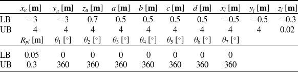
The resolution of the optimization problem was performed using the particle swarm optimization (PSO) algorithm [Reference Eberhart and James33] according to the parameters listed in Table I. The upper and the lower boundaries of each design parameter are summarized in Table II.
The upper and the lower boundaries of the design vector variables.

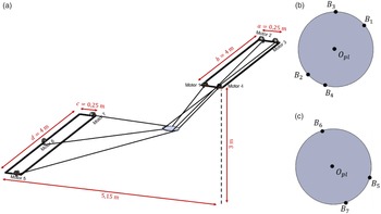
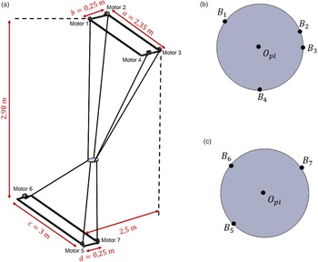
A representation of the optimal robot design is shown in Fig. 9. Its corresponding design vector
 $\textbf{I}^{\textbf{*}}$
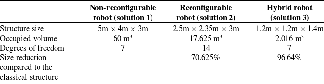
is given in Table III. In spite of integrating the minimum robot size criterion, the obtained solution measures
 $5\textrm{m}\times 4\textrm{m}\times 3\textrm{m}$
. The size of the structure is justified by the large prescribed rotational workspace (
 $\psi \in \left[-12^{\circ},263^{\circ}\right], \theta \in \left[5^{\circ},88^{\circ}\right],\text{ and }\phi \in \left[-80^{\circ},268^{\circ}\right])$
and the safety constraints. Clearly, such a robot cannot be used in home or in doctor’s office practically. Multiple issues related to space, installation, and ergonomy that make its exploitation complicated will occur.
(a) 3D representation of the optimal robot structure, (b) top view, and (c) bottom view of end-effector.

Optimal design vector parameters.

The next two sections propose different methods to solve this issue.
4. Solution of a reconfigurable robot
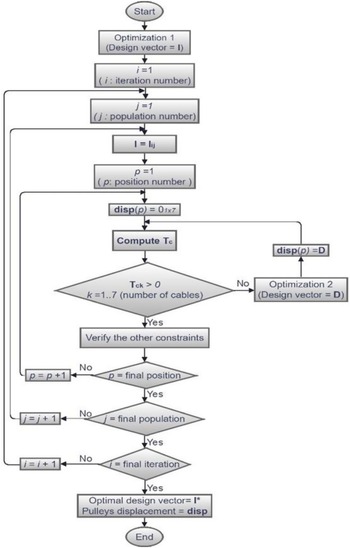
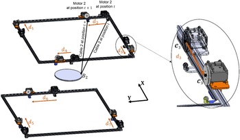
The flowchart in Fig. 10 presents an algorithm intended to address the sizable structure of the rehabilitation CDPR resulting from the previous optimization. It consists of considering a reconfigurable aspect to the robot to find the optimal and smallest robot able to cover the whole rotational workspace. The actuators are then mounted on motorized sliders (see Fig. 11) so that their positions can change whenever a pose of the end-effector cannot be reached. The pulleys of centers
 $\boldsymbol{\mathcal{C}}_{1}, \boldsymbol{\mathcal{C}}_{3},\boldsymbol{\mathcal{C}}_{5},$
and
 $\boldsymbol{\mathcal{C}}_{7}$
can translate along the
 $\textbf{X}$
-axis. The others,
 $\boldsymbol{\mathcal{C}}_{2}, \boldsymbol{\mathcal{C}}_{4},\boldsymbol{\mathcal{C}}_{6},$
along the
 $\textbf{Y}$
-axis, as shown in Fig 11. These new positions taken for each pose of the mobile platform are expressed by Eq. (26). The proposed method is composed of two nested optimizations. The first one searches for the optimal robot structure. Its formulation is the same as detailed in Section 3, where the patient’s safety and the energy consumption reduction are the selected constraints. The second optimization is responsible for the robot reconfiguration. It allows finding the optimal displacement
 $d_{i=1..7}$
of each actuator relative to all the prescribed poses of the end-effector. In other words, for each robot structure, selected by the first optimization problem, all the possible locations of the actuators are investigated to check the reachable workspace and the constraints satisfaction. The formulation of the second optimization is given by Eqs. (27)–(31).
 \begin{equation} \boldsymbol{\mathcal{T}}^{\prime}=\left[\begin{array}{c@{\quad}c@{\quad}c} x_{u}+d_{1} & y_{u} & z_{u}\\ x_{u} & y_{u}-b+d_{2} & z_{u}\\ \\[-7pt] x_{u}-a+d_{3} & y_{u}-b & z_{u}\\ \\[-7pt] x_{u}-a & y_{u}+d_{4} & z_{u}\\ \\[-7pt] x_{l}-c+d_{5} & y_{l} & z_{l}\\ \\[-7pt] x_{l} & y_{l}-d/2+d_{6} & z_{l}\\ \\[-7pt] x_{l}-c+d_{7} & y_{l}-d & z_{l} \end{array}\right] \end{equation}
where
 $d_{i}$
denotes the displacement of motor
 $i$
.
 \begin{equation} \min \left(\mathcal{L}\left(\textbf{D}\right)\right) \end{equation}
 \begin{equation} \textbf{D}=\left[\textrm{d}_{1},\textrm{d}_{2},\textrm{d}_{3},\textrm{d}_{4},\textrm{d}_{5},\textrm{d}_{6},\textrm{d}_{7}\right] \end{equation}
 \begin{equation} \mathcal{L}\left(\textbf{D}\right)=\left| \left| \min \left(T_{c}\right)\right| -{T_{c}}_{min}\right| +{g}_{1}+{g}_{2} \end{equation}
 \begin{align} {g}_{1}=\begin{cases} 0 & if\ 0\lt {T_{c}}_{min}\leq T_{ci}\left(j\right)\leq {T_{c}}_{max} \\ \Psi & \text{otherwise} \end{cases} \end{align}
 \begin{align} {g}_{2}=\begin{cases} 0 & \textrm{if}\ \text{the displacement is on the robot frame} \\ \Psi & \text{otherwise} \end{cases} \end{align}
 $\Psi$
is a large scalar.
The flowchart of the proposed method with the reconfigurable robot.

Illustration of the reconfigurable aspect.

The different steps of this algorithm are listed below:
-
1. Run the first optimization (computing the candidate
 $\textbf{I}$
).
-
2. For each candidate and each end-effector position, compute the cable tensions
$\textbf{T}_{\textbf{c}}$
. -
3. If for a pose
$p$
, at least one cable tension is negative, perform the second optimization in order to reach this pose. The obtained displacement is then stored in the variable
$disp$
. -
4. Verify the collision constraints.
-
5. Repeat these steps until the last iteration of the first optimization.


The optimal solution
 $\textbf{I}^{\textrm{*}},\text{given in Table }IV,$
and their corresponding displacements are then used for the robot design. Figure 12 depicts the reconfigurable robot structure where the end-effector is at a midway position.
Optimal design vector parameters.

(a) 3D representation of the optimal reconfigurable robot structure, (b) top view, and (c) bottom view of end-effector.

Adding a reconfigurable aspect to the robot allows reducing considerably its structure size from
 $5\textrm{m}\times 4\textrm{m}\times 3\textrm{m}$
to
 $2.5\textrm{m}\times 2.35\textrm{m}\times 3\textrm{m}$
. This reduction is evaluated as 70.6% of the occupied volume. Despite the considerable decrease, this solution dimensions are still inconvenient with the target application. In addition, it presents the inconvenience of adding seven supplementary dof, which are the translations of the seven actuators. Thus, an accurate command schema must be established to control the 14 dof simultaneously (7 dof for the actuated pulleys and 7 dof for the motorized sliders).
As a conclusion, the reconfigurable aspect does not allow solving efficiently the size issue. Also, it makes the robot control more complex. Hence, the necessity of finding another solution allows to cover the large prescribed workspace with a smaller structure size.
5. Hybrid robot solution
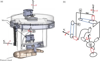
The two proposed solutions presented above are not adequate with rehabilitation devices. A more compact structure is needed to facilitate the robot manipulation. In this context, the solution of a hybrid system is proposed in this section. It consists of designing an actuated gimbal, represented in Fig. 13, composed of three motors to maintain the patient’s hand orientation. Each motor controls one Euler angle. This design allows an infinite rotation of
 $\psi$
and
 $\phi$
around the axes
 $\textbf{Z}_{\textbf{L}}$
and
 $\textbf{Z}_{\textbf{L}}^{\prime\prime}$
, respectively, and a rotation of
 $\theta$
from −90° to 90° around
 $\textbf{X}_{\textbf{L}}^{\prime}$
axis. Thus, all the prescribed rotational workspace is covered (see Fig. 3(c)). The orientations of the orthosis around
 $\textbf{Z}_{\textbf{L}}$
and
 $\textbf{X}_{\textbf{L}}^{\prime}$
are assured with the belt and pulley systems and the third rotation uses a rigid coupling. Roller bearings are used for the rotational guidance. The patient holds the orthosis by a handle located at the bottom.
(a) CAD of the actuated orthosis and (b) its kinematic design (active pivot links in red).

The three translational dof are supported by four cables. This hybrid robot allows firstly to combine the advantages of serial manipulators in terms of their large rotation amplitudes with those of the cable-driven parallel manipulators in terms of their expended translational workspace. Secondly, to reduce the risk of the different types of collisions detailed above, since fewer cables are used and thus bringing more security to the user.
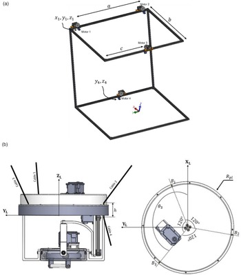
The new design vector
 $\textbf{I}$
, whose parameters are graphically represented in Fig. 14(a), is given by Eq. (32).
 \begin{equation} \textbf{I}=\left[x_{1},y_{1},z_{1},a, b, c, y_{4},z_{4},\theta _{3},\theta _{4}\right] \end{equation}
Representation of the design vector parameters (a) on the robot structure and (b) on the actuated orthosis.

The positions of the points
 $\mathcal{T}_{\textrm{i}}$
(see Fig. 4) are gathered in the following matrix:
 \begin{equation} \boldsymbol{\mathcal{T}}=\left[\begin{array}{c@{\quad}c@{\quad}c} x_{1} & y_{1} & z_{1}\\ \\[-8pt]x_{1} & y_{1}-a & z_{1}\\ \\[-8pt]x_{1}-b & y_{u}-c & z_{1}\\ \\[-8pt]x_{1} & y_{4} & z_{4} \end{array}\right] \end{equation}
In order to maintain the
 $\textbf{Z}_{\textbf{L}}$
-axe of the orthosis colinear to the
 $\textbf{Z}$
-axe of the robot fixed structure, the anchor points
 $B_{1},B_{2},$
and
 $B_{3}$
are located at equiangular positions (see Fig. 14(b)). Thus,
 $\theta _{1}$
and
 $\theta _{2}$
are expressed as follows:
 \begin{equation}{\theta _{1}}=\theta _{3}-120\end{equation}
 \begin{equation}{\theta _{2}}=\theta _{3}+120\end{equation}
The upper and the lower boundaries of each design parameter are given in Table V.
The upper and the lower boundaries of the design vector variables.

Similar to the two previous optimizations, the PSO algorithm was used for the problem resolution. A 3D representation of the obtained solution, whose optimal design vector
 $\textbf{I}^{\textbf{*}}$
is given in Table VI, is illustrated in Fig. 15.
The upper and the lower boundaries of the design vector variables.

Representation of the optimal hybrid robot.

It is known that generally hybrid systems reduce the dynamic performances due to the extra load and inertia added to the moving parts. In our case, the orthosis prototype was made mainly in PLA; thereby, it has a low weight. In addition, all the movements are performed at a normal speed which reduces the potential additional inertia.
A comparison between the three proposed solutions is summarized in Table VII.
Comparison between the three proposed solutions.

6. Conclusion
This paper discusses the optimal design of a 6-dof CDPR for rehabilitation purposes. In this context, a motion capture system was set up to record the subject’s motion while performing a set of ADLs prescribed by physiotherapists. The collected measurements were then analyzed to identify the robot task workspace. These data present a large rotational workspace, which is paradoxical with the known characteristics of CDPRs. A first optimization was performed where minimizing the robot size is the considered criterion. Regarding its constraints, they were based mainly on saving the energy consumption and ensuring the patient’s safety by avoiding all types of potential collisions with cables. The results of this optimization showed that a large size robot structure is needed to cover all the prescribed rotational workspace, which is not desirable in rehabilitation applications. Secondly, the solution of a reconfigurable robot was proposed. It consists of changing the positions of the actuators whenever a pose of the end-effector cannot be reached. This method allows covering a large rotational workspace with the smallest robot structure. Despite the considerable reduction of the robot dimensions, the obtained solution still has a large size for the target applications. Finally, the approach of a hybrid robot is proposed, where the end-effector rotations are supported by an actuated orthosis, and its translations are ensured by four cables. This last solution presents an acceptable structure size for the target application.
Conflicts of interest
The authors declare no conflict of interest.
Financial support
This work was financially supported by the “PHC Utique” program of the French Ministry of Foreign Affairs and Ministry of Higher Education, Research and Innovation, and the Tunisian Ministry of Higher Education and Scientific Research in the CMCU project number 19G1121.
Ethical considerations
None.
Authors’ contributions
M.A.L., J.S., L.R., A.C., A.M., S.B., and S.Z. have organized and supervised the work and reviewed the paper. F.E. conducted the data analysis and wrote the paper draft. M.A.L. and A.C. have administered the project. All authors have read and agreed to the published version of the manuscript.