1. INTRODUCTION
With the advent of commercially available pulse-based ultra-wideband (UWB) ranging devices, study of GPS real-time kinematic positioning (RTK) augmented with multiple UWB ranges became feasible. This paper presents, to our knowledge, the first tightly-coupled integration of GPS and UWB for precision applications. The tightly-coupled navigation estimation approach combines GPS and UWB at the measurement level as inputs to an extended Kalman filter. The ability to perform RTK improves significantly with UWB augmentation when GPS signal conditions and GPS satellite availability are degraded.
RTK positioning using GPS provides centimetre-level accuracy with good quality signal conditions and high satellite availability. This technique is now common in industry but is limited in application primarily due to signal masking, attenuation and multipath in hostile environments. Urban canyons, forests and congested construction sites are prime examples of environments where GPS RTK surveying fails to operate well. At a minimum, GPS RTK requires four satellites with good positioning geometry. In fact, many commercial systems often fail to fix carrier phase ambiguities unless five satellites are present. Hence, in order to maintain centimetre-level accuracies in such environments, a method to augment GPS RTK under sub-optimal signal conditions is required.
Increasing the number of available satellites can be achieved by utilizing satellite based augmentation systems (SBAS, e.g. WAAS) and other Global Navigation Satellite Systems (GNSS, e.g. GLONASS). For example Wanninger and Wallstab-Freitag (Reference Wanninger and Wallstab-Freitag2007) recently investigated the current integration of GPS, GLONASS and SBAS for RTK. The additional signal processing requirements add complexity and cost to the RTK receiver used for surveying. In deep urban canyons, high buildings block satellite signals with low to medium elevation angles and significantly degrade the solution geometry, or dilution of precision (DOP). This in turn drastically reduces the improvement achieved when using additional satellite systems. Additional satellites always benefit a navigation solution but the DOP is essentially limited by signal masking. Thus, additional augmentation is still required.
GPS RTK can be successfully augmented using pseudolites, which are ground based, in-band, GPS-like (i.e. pseudo-satellite) transmitters (Cobb, Reference Cobb1997). The GPS receiver requires software modifications to enable pseudolite usage but generally no additional receiver hardware is required. The near/far problem applies to pseudolites because as the receiver approaches the transmitter the pseudolite signal becomes strong enough to jam the relatively weak signals from the distant GPS satellites. This can be somewhat mitigated using pulsed signals (Cobb, Reference Cobb1997). The use of pseudolites is constrained by the need for licenses to transmit within the protected GPS frequency bands. Pseudolites also require timing synchronization with GPS. Due to these constraints, pseudolites are not suitable for widespread use but are well suited for RTK applications where fixed infrastructure is available such as deep, open pit mining (Stone and Powell, Reference Stone and Powell1998), deformation monitoring (Dai et al, Reference Dai, Wang, Rizos and Han2002) and for precision approach and landing systems for aircraft (Bartone and Kiran, Reference Bartone and Kiran2001).
Augmentation with wideband ground-based ranging systems (80–100 MHz bandwidth) that operate in unlicensed bands such as presented in Zimmerman et al (Reference Zimmerman, Cobb, Bauregger, Alban, Montgomery and Lawrence2005) and in Barnes et al (Reference Barnes, Rizos, Kanli and Pahwa2006) extend RTK capabilities using carrier phase processing techniques similar to those used in GPS. Zimmerman et al (Reference Zimmerman, Cobb, Bauregger, Alban, Montgomery and Lawrence2005) describes a system operating using X-band signals (9·5 to 10·0 GHz) and the system described in Barnes et al (Reference Barnes, Rizos, Kanli and Pahwa2006) operates using ISM signals centred at 2·4 GHz. These are time-of-arrival systems and synchronized timing is, therefore, required. The time-synchronization requirements for these systems are high if centimetre-level positioning is desired. This requirement also implies that these systems are difficult to deploy rapidly or on an ad-hoc basis for temporary surveying. These systems are very applicable for surveying in an environment suitable for fixed infrastructure. In fact, these systems derive from research into the use of pseudolites and offer solutions that resolve the pseudolite near/far problem and that do not require licensing. The primary disadvantages of these systems are high cost and the complexity of integration with GPS.
Of late, there is intense interest in UWB due to the release in 2002 of a tremendous 7·5 GHz of unlicensed spectrum by the United States Federal Communications Commission (FCC) (FCC, 2002). UWB has many advantages including signal robustness to interference, high communications capacity, resistance to multipath, and fine time resolution (e.g. cm level).
The FCC's Report and Order allows unlicensed use of spectrum mainly between 3·1 GHz and 10·6 GHz albeit at extremely low power (maximum of −41 dBm/MHz). It is intended primarily for high data rate (e.g. 400 Mbps), short range (e.g. 10 m), wireless communications and also for low data rate (e.g. 150 kbps), moderate range (e.g. 200 m), very low power, communications such as for low cost sensor networks (e.g. IEEE-802.15.4a (2007)). UWB ranging sensors well fit the latter category and offer centimetre-level ranging precision and the ability to readily distinguish between the line-of-sight signal and multipath signals.
UWB can be used in synchronous time-of-arrival systems or directly using a method of asynchronous ranging referred to as two-way time-of-flight ranging. Pulse-based UWB methods are prevalent in available ranging systems and carrier phase based techniques similar to GPS are not necessary. UWB is of particular interest to position and navigation applications because of the huge bandwidth available for time transfer (i.e. high precision ranging). The level of complexity to deploy and integrate UWB with other systems is very low because asynchronous ranging techniques can be used. With low cost, low complexity, high resistance to multipath, and the potential for centimetre level range measurements (MacGougan et al, Reference MacGougan, O'Keefe and Klukas2009), UWB technology is very suitable to augment high precision surveying equipment such as GPS RTK. The primary problem with UWB ranging is limited operational range. Commercially available ranging systems are currently limited to about 200 m; however, experimental results in Fontana (Reference Fontana, Smith and Cloude2002) have shown operational ranges up to 2 km although the system tested would not meet unlicensed FCC specifications. It is expected that this can be increased while still meeting the FCC specifications but the operational range is not likely to match that of wideband ranging systems. Another drawback concerning UWB augmentation is that the FCC states that outdoor UWB systems are not to be used as fixed infrastructure. This limits the application of UWB for augmentation purposes to temporary usage unless a license is obtained. Applications like deep open-pit mining will require a license. In this case the operational range of the radios can likely be extended with higher emission limits to match that of wideband systems.
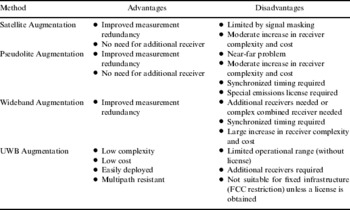
Table 1 provides an overview of the advantages and disadvantages of RF-based methods used to augment GPS for high precision RTK surveying. The best approach is a combination of satellite augmentation and ground-based augmentation.
Advantages and disadvantages of various RF-based augmentation methods.

GPS+UWB integration was discussed by Hide et al (Reference Hide, Moore and Hill2007) and limited results using loose-coupling have been demonstrated by Gonzalez et al (Reference Gonzalez, Blanco, Galindo, de Galisteo, Fernaindez-Madrigal, Foreno and Martinez2007), Fernandez-Madrigal et al (Reference Fernandez-Madrigal, Cruz-Martin, Gonzalez, Galindo and Blanco2007), and Tanigawa et al (Reference Tanigawa, Hol, Dijkstra, Luinge and Slycke2008). The main contribution of this paper is to propose and demonstrate tight-coupling of GPS and UWB for high-precision applications. In the remainder of the paper, RTK and UWB are introduced, a filter to integrate the two systems is presented, and test results with both static and kinematic data are presented and analyzed.
2. REAL-TIME KINEMATIC GPS
Real-time kinematic positioning with GPS utilizes double-differenced carrier phase observations and solves the associated unknown integer valued carrier phase ambiguities. This is well described in GPS textbooks such as Misra and Enge (Reference Misra and Enge2006).
Measurements are first differenced with a reference receiver at a known location, thereby reducing spatially correlated errors such as tropospheric and ionospheric delay. The measurements are then differenced between satellites and the effect of the receiver clock offset is eliminated. The resulting double-differenced measurements are modelled by:

where ∇ΔΦ is the double-differenced carrier phase measurement, ∇Δρ is the double-differenced geometric distance between the estimated position and the satellite positions, ∇ΔλN is an integer valued ambiguity multiplied by the carrier wavelength, and ε includes multipath, noise, and unmodelled error effects.
GPS RTK generally uses extended Kalman filtering, an efficient recursive filter that estimates the error states of a linearized dynamic system (Brown and Hwang, Reference Brown and Hwang1997), to estimate unknown parameters. The integer nature of the ambiguities is then utilized, using techniques such as the LAMBDA method (De Jonge and Tiberius, Reference De Jonge, Tiberius and G. B.1996), to provide 2 cm to 3 cm position solutions in good GPS signal conditions.
3. ULTRA WIDEBAND
Historically UWB signals are synonymous with impulse radio, also known as baseband radio, but large bandwidth multi-carrier methods, such as OFDM, can also be considered UWB based on the FCC definition. The reader is invited to consult Reed (Reference Reed2005) for further general information regarding UWB signals and a detailed and thorough history of UWB is given by Barrett (Reference Barrett2001).
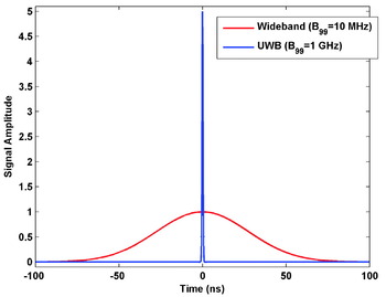
Ultra-wideband (UWB) signals are signals with large relative or very large absolute bandwidths. On the other hand, in the time domain, UWB signals have very fine time resolution. For intuitive comparison with wideband signals, a wideband signal and an UWB Gaussian pulse signal are shown in Figure 1.
Wideband and UWB signals.

3.1. UWB Signals
UWB is broadly categorized into short pulse based (impulse) UWB (e.g. nanosecond long Gaussian pulses) and multi-carrier UWB (e.g. OFDM). Impulse methods sometimes make use of a carrier to better use the spectrum available given the FCC constraints. A few studies such as Parikh and Michalson (Reference Parikh and Michalson2008) have examined multi-carrier methods for ranging. Ranging based on impulse UWB is much more prevalent in the literature and commercial systems that use this technique are already available. No commercial systems that use the multi-carrier method for ranging are yet known. For these reasons, this paper is specific to impulse UWB.
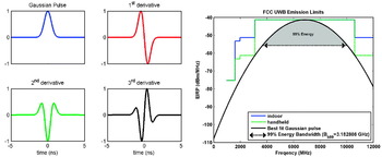
Impulse UWB uses pulses which are very short. These pulses range from a few tens of picoseconds to a few nanoseconds. Simple analytic pulse waveforms can be obtained from the Gaussian pulse and its derivatives. The Gaussian pulse is described by Equation 2.

where σ is related to the pulse width, and μ is the midpoint of the pulse in time. The Gaussian pulse and its first three derivatives are shown in Figure 2 (Left). The first derivative of the Gaussian pulse is referred to as a Gaussian monocycle.
(Left) The Gaussian pulse and its derivatives. (Right) Gaussian pulse which best fits the FCC emission limits.

These pulses, while very convenient for analytic purposes, are not directly suited for practical application because of the need to fit the available spectrum as mandated by the FCC. For example, to make the most use of the FCC allocation in the 3·1 GHz to 10·6 GHz band, a Gaussian pulse with a 20 dB baseband bandwidth of approximately 3·18 GHz is modulated with a 6·85 GHz carrier signal. The resulting spectral representation is shown in Figure 2 (Right). Modulation with a carrier, pulse shaping, and bandpass filtering of the basic Gaussian derived waveforms are effective means of generating FCC compliant pulses. For ranging applications the pulse repetition rate is very low compared to communications systems. With lower pulse repetition frequency, pulses can have more energy and hence can travel farther to provide sufficient operational ranging performance.
3.2. UWB ranging radios used
The University of Calgary obtained four ranging radios from Multispectral Solutions Inc (MSSI) suitable for testing and analysis. The radios utilize impulse UWB signals and two-way time-of-flight ranging. The MSSI ranging radios modulate a 6·35 GHz C-Band carrier with a Gaussian-like pulse of approximately 3 ns duration resulting in a signal with a 10 dB bandwidth of approximately 500 MHz. The radio design is described well by the US patent 5901172 (Fontana, Reference Fontana1999). The ranging measurements obtained from these radios have a precision better than 15 cm (one standard deviation); however, the radios quantize their range measurement output to half a nanosecond (~15 cm). Raw measurement accuracy suffers due to turn-around time bias and scale factor error (MacGougan et al, Reference MacGougan, O'Keefe and Klukas2009). A single radio can make ranging measurements to a number of other radios with measurement rates in excess of 10 Hz.
3.3. Two-way time-of-flight ranging
Ranging observations cannot be produced directly from time-of-arrival (TOA) measurements unless the transmitter and receiver are synchronized in time. For UWB ranging, this is not generally the case. UWB ranging radios are used in TOA systems such as one commercially available from Multispectral Solutions Inc (MSSI) which is described by US patent 6054950 (Fontana, Reference Fontana2000).
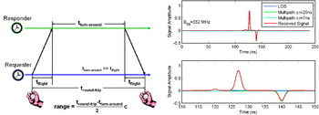
Asynchronous ranging, that is ranging in the absence of clock synchronization, is a method of obtaining a range measurement wherein the requester device uses knowledge of its own clock and a known turn-around-time in the responder to measure a two-way range as shown in Figure 3 (Left). This method is used by at least two commercial manufacturers of UWB ranging equipment (including MSSI). Two-way time-of-flight ranging is well suited for outdoor use given the FCC restriction of non-fixed infrastructure outdoors. That restriction implies difficulties for time synchronized UWB systems outdoors.
(Left) Two-way time-of-flight ranging. (Right) Non-line-of-sight measurement.

3.4. Errors in UWB ranging
Radios that process UWB signals have the ability to distinguish well between the line-of-sight signal and most multipath. In general, any multipath that arrives with a delay less than the width of the line-of-sight pulse will result in distortion of the received line-of-sight pulse shape and the multipath cannot be distinguished. Maximum delay estimate error induced by multipath is one half of the pulse width.
While UWB is very good at distinguishing between the line-of-sight signal and multipath when the line-of-sight signal is detectable, there is a significant danger of measuring the first strongest multipath otherwise. This is demonstrated in Figure 3 (Right). This figure shows a weak line-of-sight signal, a multipath signal with 7 ns delay, and a multipath signal with 20 ns delay. If the line-of-sight signal is too weak to be detected, the first strongest multipath will be measured and measurement blunders of a few metres to tens of metres are possible.
It is important to note that the speed of light used for UWB ranging is light speed ‘in air’ and is a function of the temperature, pressure, and water vapour pressure (Rüeger, Reference Rüeger1990). The velocity correction can be as much as 300 ppm (with respect to light speed in a vacuum).
The two-way time-of-flight methods used by the UWB radios in this study exhibit systematic measurement error effects including a bias error and a scale factor error. These are described in MacGougan et al (Reference MacGougan, O'Keefe and Klukas2009) which investigated line-of-sight UWB range measurement errors using two types of UWB ranging radios (including the MSSI type). The error effects are explained in terms of bias induced likely by the radio oscillator frequency offsets, and a scale factor error likely due to geometric walk that results from the pulse detection and fine timing methods used by the UWB radios to estimate the time-of-arrival of the UWB signal. The bias and scale factor errors are fairly stable during testing but vary from run-to-run if the power supply is cycled.
4. MULTIPLE UWB RANGE AUGMENTED GPS RTK
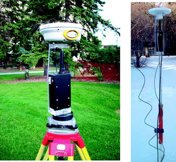
The form factor for the UWB radios, as shown in Figure 4, is rugged and suitable for field applications with a built-in rechargeable battery. Data collection software was written to configure the radios and collect ranging data using the RS232 protocol. Measurements from the radios were collected using a PC which is synchronized to GPS time to within 20 ms or better. To integrate the UWB radio with the GPS receiver, an UWB-GPS antenna mount was built. The mount design is such that the phase centres of the GPS receiver and the UWB antenna are vertically co-linear. The UWB radio mounted beneath the GPS antenna is shown in Figure 4. UWB radios were placed over pre-surveyed locations on survey tripods to act as reference UWB stations. The survey system consists of a pole mounted UWB radio mounted co-axially beneath a GPS antenna. As the position of the phase centre of the GPS antenna is estimated in the estimation filter, the lever arm between the UWB antenna and the GPS antenna phase centre must be monitored. A tilt sensor with an accuracy of about 2° is used to monitor this lever arm. Additional noise based on the tilt angle is added to the UWB measurement standard deviation used in the filter. The approximate lever arm between the GPS antenna and the UWB antenna is 12 cm. At a tilt of 20°, this adds approximately 4 cm of measurement noise.
GPS and UWB equipment photos.

Given the in-run stability of the bias and scale factor errors determined in MacGougan et al (Reference MacGougan, O'Keefe and Klukas2009), it is likely that bias and scale factor errors can be estimated in real-time as additional states in a tightly-coupled GPS+UWB extended Kalman filter.
The software developed for this research utilizes a sequential extended Kalman filtering approach. Measurements are collected during testing and are post-processed with a simulated real-time approach. The filter uses 5 Hz UWB range measurements from up to three UWB reference stations as well as 5 Hz differential GPS L1 pseudorange and carrier phase measurements. This study utilizes GPS L1 measurements with relatively short baselines of less than 1 km (i.e. strong spatially correlated errors). Utilizing GPS L2 phase measurements aids the ability to estimate fixed integer ambiguities but the focus of this research is the examination of the impact of UWB range augmentation and this impact is assessed well with L1 only (for short baselines).
A two-stage estimation approach is used. First, the unknown position, GPS receiver clock offset and single-difference GPS ambiguities are estimated (i.e. between-receiver differencing only). This estimator is augmented to include bias and scale factor estimates for each UWB range pair. The single-difference float solution ambiguity estimates are then differenced between satellites and the LAMBDA method (De Jonge and Tiberius, Reference De Jonge, Tiberius and G. B.1996) is used to obtain double-difference integer ambiguities which are used to produce an RTK position solution.
The sequential extended Kalman filter error state vector is:

where x, y, and z are the Earth centred Earth fixed error states of the test unit, cδT is the GPS receiver clock offset error state, b a, b b, and b c are the UWB bias error states, sf a, sf b, and sf c are the UWB scale factor error states, and λN i is a GPS ambiguity error state (one for each carrier phase measurement).
The sequential extended Kalman filter prediction step is:
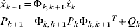
where Φk,k+1 is the state transition matrix, P is the state variance-covariance matrix, and Q is the process noise matrix.
The Kalman filter models the position error states as random walk processes with process noise suitable for mildly dynamic operations (i.e. land surveying). When the tilt sensor indicates level operation for more than 1 second, this process noise is adjusted for static operation. The receiver clock offset error state is also treated as a random walk process; however, it is given very large process noise with each prediction step so that the clock offset is fully estimated at each update (i.e. it is not filtered).
Each UWB bias error state is modelled as a random walk process with process noise that allows the bias to change slowly over time. The bias may change over time since the two-way time-of-flight bias is a function of the stability of the UWB radio oscillators which likely vary with temperature. Each UWB scale factor error state is modelled as a random walk process with very little process noise as it is not expected to change while the UWB radios are powered up. This is reasonable given previous empirical testing and since the threshold used for the leading edge detector by the MSSI radios is set once when the device is turned on and remains constant during the test (Fontana, Reference Fontana1999). The update steps of the filter proceed with each measurement sequentially.
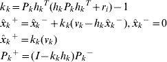
where k k, a row vector, is the Kalman gain for the measurement, h k is the design vector for the measurement, r i is the variance of the measurement, v k is the measurement innovation, ‘+’ denotes after this measurement update and ‘−’ denotes before this measurement update.
The design vectors for a GPS pseudorange measurement, a GPS carrier phase measurement (also called accumulated Doppler range hence the ‘adr’ subscript), and an UWB range measurement respectively are:
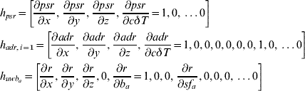
Since the range of the UWB bias is known based on the quality of the oscillators used (e.g. for 20 ppm, the worst case bias is ±1·23 m), and the range of the scale factor error is well known from line-of-sight testing in MacGougan et al. (Reference MacGougan, O'Keefe and Klukas2009), inequality constraints are used in the filter. After each measurement update, the UWB bias and scale factor values are checked to determine if the minimum or maximum value is exceeded. If a boundary has been crossed, a pseudo-measurement update is performed to force the solution to the known range of values. This method of applying inequality constraints to an extended Kalman filter adds a minimal amount of information to the filter to achieve the constraint (Richards, Reference Richards1995).
Innovation testing as described by Teunissen (Reference Teunissen1990) is employed for each measurement during each sequential update step to detect and then exclude potential measurement blunders.
5. RESULTS – STATIC TESTING
The results of static testing are provided in this section and kinematic testing in Section 6. The general method is to use an environment with good quality RTK conditions so that a reference solution can be generated and then reprocess the data using an artificially induced elevation mask.
5.1. Static testing in nominal signal conditions
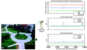
GPS and UWB range data was collected at a static point at the University of Calgary as shown in Figure 5 (Left). The static point was surrounded by three UWB reference ranging transceivers that were set up at pre-established surveyed positions. The GPS base station was located approximately 140 m away on the roof of the engineering building. This test assesses the performance of RTK using GPS only and combined GPS with UWB ranges for four minutes using a 13° elevation mask angle. The UWB bias and scale factor errors were pre-determined by post-processing and were not estimated by the filter in this case.
(Left) Static GPS+UWB RTK test site. (Right) Number of observations and DOP, Static Test.

The number of available GPS satellites and UWB range measurements are shown in Figure 5 (Right) along with the resulting horizontal DOP (HDOP) and vertical DOP (VDOP) values using only GPS and GPS+UWB. The UWB reference stations and the test station are basically on a horizontal plane and thus the HDOP directly improved. The improvement in the ability to estimate the horizontal position means that the GPS observations can better estimate height and consequently VDOP improves.
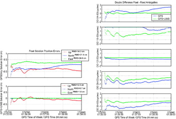
The float solution position errors are shown in Figure 6 (Left). The GPS-only solution has errors close to half a metre. The GPS+UWB solution has sub-decimetre level accuracy in this case because the UWB bias and scale factor errors are well calibrated. The differences between the float solution double-differenced carrier phase ambiguity estimates and the known fixed double-differenced ambiguity values are shown in Figure 6 (Right). There is clearly improvement in the convergence with the inclusion of the UWB ranges.
Static test: (Left) Float solution; (Right) Float solution ambiguity estimates.

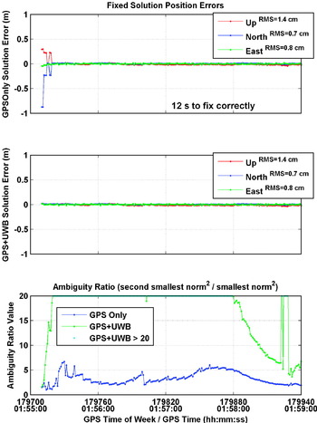
The LAMBDA method was applied to the float solution at every epoch (i.e. epoch by epoch ambiguity fixing) by first double differencing the estimated single-difference float ambiguities. This approach is identical to double differencing the observations as any residual clock effect on the single-difference ambiguities is cancelled in the differencing process. With such a short baseline, and good DOP, both the GPS and GPS+UWB solutions are able to fix ambiguities correctly. The resulting fixed solution position errors are shown in Figure 7. The accuracy obtained after fixing correctly is identical and driven by the precision of the carrier phase measurement. The GPS+UWB solution fixed ambiguities correctly on the first epoch. The GPS only solution required 12 s to fix correctly.
Static Test: Fixed solution.

The so-called F-ratio test is often used to validate integer ambiguity search procedures (Counselman and Abbot, Reference Counselman and Abbot1989). The ratio value is given by:
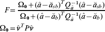
where â is the vector of estimated float ambiguities, ă sb is the second best vector set of fixed ambiguities found, ă b is the best vector set of fixed ambiguities found,  is the vector of ambiguity residuals, and P is the weight matrix for the carrier phase measurements. The critical value of the F-ratio is often chosen as 2·0 based on empirical evaluation (e.g. Euler and Landau, (Reference Euler and Landau1992) ). The ratio values computed at each epoch for the GPS only and GPS+UWB solutions are shown in Figure 7. The ratio values achieved for the GPS-only and the GPS+UWB solutions both provide strong confidence in the ambiguity set found compared to the second best set. The GPS+UWB ratio values are much larger than those of the GPS-only solution and, therefore, the relative confidence is much higher.
5.2. Static testing with a 40° elevation mask
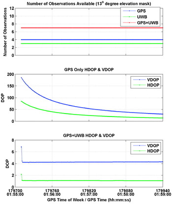
The static data was reprocessed using a 40° elevation mask to simulate RTK operation in an urban canyon or perhaps a deep open pit mine. The number of satellites available and the number of UWB range measurements available are shown in Figure 8. Only four satellites are available and thus the GPS-only solution has no redundancy. The resulting DOP values are also shown in Figure 8. The GPS-only solution has very poor DOP values whereas the GPS+UWB solution still has reasonable HDOP while VDOP is somewhat poor.
Static 40° test: Number of observations and DOP.

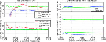
The float solution position errors are shown in Figure 9 (Left). The GPS+UWB horizontal position still has sub-decimetre accuracy. It takes nearly a minute for the GPS-only solution to converge to sub-metre level accuracy. The difference between the float solution double-differenced carrier phase ambiguity estimates and the known fixed double-differenced ambiguity values is shown in Figure 9 (Right). The double-difference ambiguities all converge to within half a cycle of the ‘true’ values for the GPS+UWB solution. The GPS-only ambiguities are off by 1 to 2 cycles after 4 minutes.
Static 40° test. (Left) Float solution; (Right) Float ambiguities.

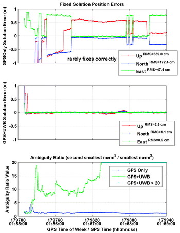
The LAMBDA method was applied to the float solution at every epoch (i.e. epoch by epoch ambiguity fixing). The resulting fixed solution position errors are shown in Figure 10. The GPS+UWB solution fixes correctly after 12 s. The GPS-only solution rarely fixes correctly during the test. It should be noted that in the GPS-only case, the fixed solution is displayed even though it fails the validation test. Throughout, different incorrect ambiguity sets are selected as shown by the biased, but precise, position solutions. The discontinuities in the solution correspond to changes in the integer estimate. This is reflected by the ratio test values shown in Figure 10. The GPS+UWB solution ratio values are well above 2·0 after 12 s whereas the GPS-only solution fails to reach suitable values to justify integer solution validity.
Static 40° Test. Fixed solution.

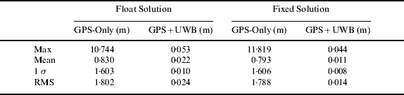
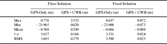
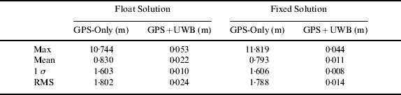
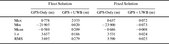
Tables 2 and 3 provide a quantitative summary of the performance of the tightly-coupled GPS+UWB solution compared to the GPS-only solution for the case given the 40° elevation mask. The tables provide results for both the float solution and the epoch-by-epoch fixed solution. The GPS-only fixed solution does not provide any improvement compared to the float solution because it fails to correctly determine the integer ambiguities. The GPS+UWB fixed solution statistics are computed after the solution has fixed correctly. In this case, the tightly coupled solution performs at the level normally expected of commercial RTK systems in open sky conditions.
Comparison of horizontal errors for the static test (40° elevation mask).
Comparison of vertical errors for the static test (40° elevation mask).
6. RESULTS – KINEMATIC TESTING
The objective of kinematic testing is two-fold. Firstly, the ability to estimate the UWB bias and scale factor states ‘on-the-fly’ is assessed. It is expected that the error levels are sufficiently stable during a typical survey (while continuous power is maintained) to result in decimetre level range accuracy after error compensation. The high positioning accuracy of GPS RTK (e.g. 2 cm) under nominal conditions is used to facilitate the estimation of the UWB bias and scale factor states. Once these states are well estimated, the corrected UWB range measurements can enable and extend RTK accuracy into conditions that are hostile to GPS alone. Thus, the second objective of dynamic testing is to assess the performance of the combined system once the bias and scale factor states are well estimated.
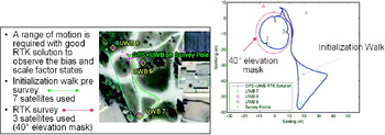
Three UWB reference stations, labelled 7, 8, and 9 in Figure 11 (Left), were set up, in a similar configuration as the static test, within 200 m of a GPS reference station located on the roof of the University of Calgary Engineering building. In order to observe the UWB bias and scale factor states, a range of motion is required with good quality GPS conditions. Once these states are sufficiently estimated, a survey may proceed in degraded GPS signal conditions with the benefit of the corrected UWB measurements. The test consists of a pre-survey initialization walk followed by walking a circular route on which there are three static test points which were pre-surveyed. This is illustrated in Figure 11 (Left). For the test system, an elevation mask of 40° is applied when entering the survey area.
(Left) The Kinematic Test; (Right) Test trajectory.

To obtain a reference trajectory during the entire survey, GPS-only results were obtained for the entire test without the 40° elevation mask. Fixed ambiguity GPS-only RTK solutions were obtained using 7 satellites for the duration of the test. The test trajectory is shown in Figure 11 (Right).
6.1. Assessing UWB Ranging
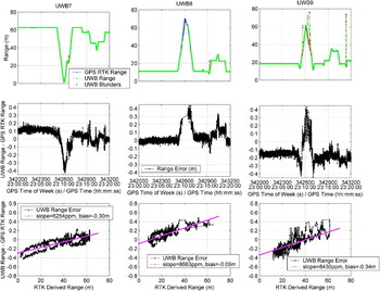
The ranges measured by the UWB pairs can be compared to the RTK solutions obtained using GPS-only. This allows assessment of the actual range errors as the RTK derived ranges are accurate to a few centimetres. Bias and scale factor estimates are obtained using a best line fit of the UWB range errors versus the GPS RTK derived range. This is shown for all three ranging pairs in Figure 12. The figure shows the UWB range measurements and the RTK derived ranges for the entire test. Some interesting behaviour is observable in Figure 12. The UWB biases are not constant and change over time. For UWB7, the range measurements for the first static period (the first 8 minutes) are not consistent with the range measurements for the second static period (from approximately 23:12 to 23:14) despite occupying the same point. The apparent UWB bias changed by about 6 cm. The temperature during testing varied from −5°C to −10°C and the radios were turned on just as the test began. It is likely that the radios warmed up as the test proceeded and that the onboard oscillators exhibit frequency bias as a function of temperature. There are also clear multipath blunders especially for the range pair marked UWB9.
UWB ranging errors.

6.2. Tightly-Coupled Test Results
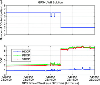
The number of double-difference ambiguities used in the GPS+UWB solution is shown in Figure 13 along with the corresponding dilution of precision (DOP) values. The epoch when the 40° elevation mask is applied is clearly evident in the VDOP and PDOP plots. Note that the HDOP degrades only slightly because of good horizontal observability due to the UWB measurements. The GPS-only solution (with the elevation mask applied) lacks observability with only 3 satellites available and it cannot maintain fixed ambiguities. In the following analysis, the GPS+UWB solution is compared to the GPS-only RTK truth solution (obtained using a 13° elevation mask for the duration of the test). There are no GPS-only results with a 40° elevation mask angle because the solution is not usable due to the lack of observability.
GPS+UWB observations and DOP.

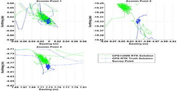
The GPS+UWB solution was able to maintain fixed ambiguity solutions for the duration of the test. The trajectory of the GPS+UWB solution closely matches that of the RTK truth solution. The differences in the computed positions are most apparent when examining the results for the static survey points. Both the GPS+UWB solution and the RTK truth solution are shown in Figure 14. The ability to measure the static survey points corresponds reasonably well with the RTK truth solutions, especially considering the 40° elevation mask. The GPS+UWB solutions differ by less than 6 cm compared to the ‘truth’ solution.
Survey points 1, 2, and 3 (GPS+UWB 40° mask).

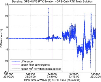
The overall accuracy of the combined GPS+UWB solution is compared to the GPS-only ‘truth’ solution by comparing the 3D baseline obtained each epoch. The GPS+UWB system performs within 1 cm of the truth solution with similar GPS conditions with the exception of an error spike due to the inclusion of a short delay UWB range blunder. This is shown in Figure 15. When the GPS conditions are degraded using a 40° elevation mask and only three satellites are used, the performance of the system is typically better than 5 cm and better than 10 cm most of the time.
Baseline differences.

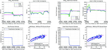
The filter estimation of the UWB bias values agree well with the post-processed line fit values. This is shown for the first UWB range pairs in Figure 16 (Left). Similar results were obtained for the other two range pairs. It is clear from the bottom left subplot in Figure 16 that the UWB bias requires the pre-survey initialization walk to estimate the UWB bias with sufficient accuracy. The estimate of the UWB scale factor value also agrees reasonably well with the post-processed line fit values. This is shown in Figure 16 (Right).
(Left) UWB7 bias estimate. (Right) UWB7 scale factor estimate.

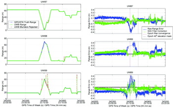
Numerous UWB blunders were detected in testing as shown in Figure 17 (Left). For example, the UWB9 range pair exhibited multiple blunders with errors ranging from a few metres to tens of metres. The filter performed well in detecting most of these blunders and excluding them from the filter. However, as shown in the baseline difference figure (Figure 15), a short delay multipath blunder went undetected and affected the solution accuracy.
(Left) UWB ranges and blunders. (Right) UWB range errors.

Comparing the raw range error with the range error corrected with the filter bias and scale factor values assesses the ability of the filter to ‘correct’ the UWB range measurements. This is shown in Figure 17 (Right) and it is clear that the filter reduces the UWB measurement error but there is room for improvement. Allowing the UWB transceivers warm-up time so that the temperature of their oscillators is stable should improve bias stability. The use of temperature controlled or ovenized oscillators would improve bias stability as well. The use of a better pulse detection discriminator, such as the constant fraction discriminator (Amann et al, Reference Amann, Bch, Myllyla and Rioux2001), rather than the simple leading edge discriminator used by the UWB radios, might decrease scale factor error and improve performance.
7. CONCLUDING REMARKS
The results of static testing demonstrated that utilizing two-way time-of-flight UWB ranges with GPS RTK provides better accuracy, better ability to resolve integer ambiguities and enhanced fixed ambiguity solution availability compared to GPS alone in conditions with severe GPS signal masking.
To achieve RTK level positioning accuracy, it is important that UWB ranges are compensated for turn-around-time bias and for scale factor error. This work demonstrated that UWB errors can be successfully estimated in a real-time filter. In kinematic testing, when the GPS conditions were degraded using a 40° elevation mask and only three satellites were used, the accuracy of the tightly-coupled system was typically better than 5 cm and better than 10 cm most of the time while a GPS-only solution was unavailable.
The simplicity of utilizing two-way UWB range measurements and the moderate cost of UWB ranging devices make augmenting GPS RTK with UWB ranges very suitable for many applications. The UWB ranging technology used (500 MHz 10 dB bandwidth) provides decimetre-level measurement precision and is expected to reach centimetre-level precision as it evolves to use more of the UWB spectrum available.
This work demonstrated tightly-coupled GPS and UWB positioning in a degraded GPS environment. The degraded GPS environment was created artificially by simply excluding GPS satellites from the solution using an elevation mask. The method has not yet been demonstrated in a real-world environment. More research is required to assess if the tightly-coupled approach of combining GPS and UWB measurements is feasible for RTK surveying in an urban canyon environment with realistic multipath and signal masking conditions.
ACKNOWLEDGEMENTS
This research was supported by the Natural Sciences and Engineering Research Council of Canada (NSERC) and the Alberta Ingenuity Fund (AIF).