

1. Introduction
For many decades of the last century, arguably triggered by the discovery of the Skaergaard Intrusion in Greenland (Wager & Deer, Reference Wager and Deer1939), the science of igneous petrology was dominated by the study of layered intrusions. More recently, petrologists have made major advances in our understanding of volcanic systems; most volcanoes have an extended history involving episodes of magma migration and stalling within a complex plumbing system from which eruption is commonly triggered by the arrival of fresh magma from below. However, our knowledge of the connection between layered intrusions and volcanic rocks is relatively thin. What actually lies below a longlived volcano? How might we recognize the solidified relicts of a deeply eroded open-system magma chamber, and in particular, how might we recognize the signature of a replenishment event or an eruption? The Rum Central Complex, which has long been recognized as an open-system chamber, provides a well-exposed natural laboratory in which to address these questions.
The Eastern Layered Intrusion of Rum comprises 16 macro-scale cyclic units attributed to repeated influxes of primitive magma followed by fractionation (Brown, Reference Brown1956), but this relatively coarse division disguises a great complexity in the modal layering. The major allivalite horizons (strictly troctolites or gabbros) of the Eastern Layered Intrusion contain many subsidiary peridotite horizons (Faithfull, Reference Faithfull1985; Butcher, Young & Faithfull, Reference Butcher, Young and Faithfull1985; Renner & Palacz, Reference Renner and Palacz1987; Bedard et al. Reference Bédard, Sparks, Renner, Cheadle and Hallworth1988; Emeleus et al. Reference Emeleus, Cheadle, Hunter, Upton, Wadsworth and Cawthorn1996), ranging in thickness from several metres down to ~1 cm. In this contribution we focus on the small-scale lithological variations in the Unit 12 allivalite, using field observations, and textural and geochemical analysis of detailed logs and sampled traverses to decode the evolution of the magma chamber recorded by this level of the cumulate pile.
2. Geological background
The model for Rum first propounded by Brown (Reference Brown1956) correlated each macro-scale cyclic unit with a single injection of primitive magma, the fractionation of which resulted in an upwards sequence of olivine cumulates, troctolitic cumulates and gabbros. Huppert & Sparks (Reference Huppert and Sparks1980) refined this model by applying an understanding of the fluid dynamics of magma chamber replenishment. They suggested that replenishment by dense picrite magma formed an initially isolated layer beneath the resident cool, evolved basaltic magma. Vigorous convection in the picrite would keep the olivine in suspension until it all settled out to form a single, massive, compositionally uniform peridotite unit. Crystallization of the picrite gradually reduced its density, finally prompting overturn and mixing of the entire chamber contents, with the resumption of accumulation of troctolites.
While early models of the Rum chamber were based on the assumption of a thick magma body (~1 km: Huppert & Sparks, Reference Huppert and Sparks1980; Tait, Reference Tait1985), the current consensus is that it was an essentially sill-like chamber, or magma lens, some tens or hundreds of metres thick, periodically replenished by major pulses of picrite magma spreading out across its floor (Emeleus et al. Reference Emeleus, Cheadle, Hunter, Upton, Wadsworth and Cawthorn1996). Recognition of complex open-system behaviour was made by Renner & Palacz (Reference Renner and Palacz1987), who found isotopic evidence for multiple replenishments by relatively evolved basaltic magmas, in particular a major replenishment by basalt at the base of the Unit 14 allivalite, with a further basaltic replenishment recorded within the allivalite (supported by textural evidence: Holness, Nielsen & Tegner, Reference Holness, Hallworth, Woods and Sides2007). The transition from peridotite to troctolite in this case was clearly associated with injection of evolved magma, rather than with in situ fractionation. Evidence for within-unit replenishments of the chamber are also recorded by 87Sr/86Sr in Units 9 and 12 (data from Palacz, Reference Palacz1985).
The presence of an open-system, repeatedly replenished, magma chamber beneath the Rum volcano is not in dispute, but the details of the replenishment events themselves, and in particular the origin of the minor peridotite horizons within the major allivalites, have been the subject of lively debate. Morse, Owens & Butcher (Reference Morse, Owens and Butcher1987) cite the metasomatism commonly developed on the upper margins of the subsidiary peridotites as evidence that they formed by injection of hot primitive magma into essentially solidified troctolites. Renner & Palacz (Reference Renner and Palacz1987) also believe this is a plausible idea but suggest that the subsidiary peridotites may also represent the mixing of an injection of picritic liquid with the resident, primarily basaltic, bulk liquid, which temporarily moved the bulk liquid into the olivine primary phase field, before fractionation took it back onto the olivine–plagioclase cotectic. Maaløe (Reference Maaløe1978) suggested that the subsidiary peridotite horizons represent variations in nucleation rates of primocrysts under super-cooled conditions.
The cyclic units of the Eastern Layered Intrusion dip towards a focus along the Long Loch Fault (Fig. 1a), which is believed to have been the main conduit for the magmas parental to the Rum Layered Suite. The Eastern Layered Intrusion dips at about 10° to the west in the region of Hallival and Askival, but steepens to more than 40° in the Trollval region (Volker & Upton, Reference Volker and Upton1990). This change in dip, together with abundant evidence of soft-sediment deformation, lead Emeleus et al. (Reference Emeleus, Cheadle, Hunter, Upton, Wadsworth and Cawthorn1996) to suggest sagging of the floor cumulates towards the conduit due to episodic magma withdrawal and deflation. Extensive slumping of an unconsolidated crystal mush towards the centre of the chamber has been suggested as the cause of the pervasive magnetic fabrics in both peridotite and allivalite (O'Driscoll et al. Reference O'Driscoll, Hargraves, Emeleus, Troll, Donaldson and Reavy2007b). The allivalite portions of the cyclic units thin towards the west (Harker, Reference Harker1908), and since the dips do not change up-section, this means that the peridotites correspondingly thicken to the west (Young, Greenwood & Donaldson, Reference Young, Greenwood and Donaldson1988).
(a) Sketch geological map of Rum. (b) Close-up of the Hallival–Askival region, showing the locations of the logged profiles across the Unit 12 allivalite (labelled dots). Maps after Emeleus (Reference Emeleus1994).

While early models involved settling of crystals from cooling magma (Brown, Reference Brown1956; Dunham & Wadsworth, Reference Dunham and Wadsworth1978; Huppert & Sparks, Reference Huppert and Sparks1980), L. M. Worrell (unpub. Ph.D. thesis, Univ. Liverpool, 2002) and Tepley & Davidson (Reference Tepley and Davidson2003) advocate a major sedimentary input from large-scale dense crystal-laden flows cascading from the chamber roof and walls. In situ growth has been advocated to account for the dendritic habit of harrisite (reviewed in O'Driscoll et al. Reference O'Driscoll, Donaldson, Troll, Jerram and Emeleus2007a).
3. Sampling strategy and analytical techniques
The stratigraphy of the Unit 12 allivalite was documented in detail at 23 locations (Fig. 1), and samples were taken along three stratigraphic profiles (labelled D [GR 39696, 9631]), P [GR 39496, 95356] and J [GR 39231, 95888]) for comparison with previously published traverses (labelled b [GR 39345, 96460] and d [GR 39470, 96469] on Fig. 1; Holness, Reference Holness2005, Reference Holness2007). Traverses b and d were supplemented by additional samples adjacent to the subsidiary peridotite horizons.
To constrain the extent of approach to textural equilibrium, between 30 and 60 clinopyroxene–plagioclase–plagioclase dihedral angles were measured in each sample using a 4-axis Leitz universal stage mounted on an optical microscope, with an estimated error of ~2° for each measurement. Medians of the angle populations are reported here. The effect of plagioclase preferred orientation on angle populations is ignored, as any effect is considered to be negligible.
Mineral compositions were determined by wavelength dispersive electron microprobe spectrometry using a Cameca SX100 electron microprobe. The accelerating potential was 15 keV, with a beam current of 10 nA for major elements, and 100 nA for traces. Beam diameter was ~2 μm. Centres of five to twelve olivine grains were analysed in each sample, with analyses of the grain rims in six samples to check for compositional zoning. Up to six clinopyroxene grains and the central parts of up to eight plagioclase grains (together with grain margins for selected samples) were analysed to constrain the compositional variation in each sample.
4. Textural evolution in cumulates
In the early stages of formation of a crystal mush, the crystals (whether grown in situ or accumulated from elsewhere) generally have planar-sided growth forms. The pore structure in such a mush is controlled by grain juxtaposition which forms an impingement texture (Elliott, Cheadle & Jerram, Reference Elliott, Cheadle and Jerram1997). Further solidification results in infilling of the pore space by growth of interstitial phases (e.g. Rosenburg & Riller, Reference Rosenberg and Riller2000), inheriting the dihedral angle at pore corners. Since this original dihedral angle is generally low (with a median of 60° and a standard deviation of ~25° for impingement of planar-sided grains: Elliott, Cheadle & Jerram, Reference Elliott, Cheadle and Jerram1997; Holness, Cheadle & McKenzie, Reference Holness, Cheadle and McKenzie2005), the angle will increase during textural equilibration in the sub-solidus towards the solid–solid equilibrium angle (~120° with a standard deviation of ~15°: Vernon, Reference Vernon1968; Holness, Cheadle & McKenzie, Reference Holness, Cheadle and McKenzie2005). The extent to which this has occurred provides a measure of the time-integrated thermal history. The clinopyroxene–plagioclase–plagioclase dihedral angle, Θcpp, in undisturbed troctolites in the Rum chamber has a median value of ~80° (Holness, Reference Holness2005; Holness, Nielsen & Tegner, Reference Holness2007).
Since the closure temperature for dihedral angle change at clinopyroxene–plagioclase junctions is ~1100°C for kilometre-scale mafic intrusions in the shallow crust (Holness, Nielsen & Tegner, Reference Holness2007), Θcpp is strongly affected by processes at or near the magma–mush interface and can be used to detect late-stage infiltration of chemically unreactive silicate liquids (Holness, Reference Holness2007), and the arrival of either hot (Holness, Reference Holness2005; Holness, Nielsen & Tegner, Reference Holness, Nielsen and Tegner2007) or cold (Holness, Reference Holness2007) replenishing magma at the magma–mush interface.
5. Field observations
The Unit 12 allivalite crops out on the slopes of Hallival and Askival (Fig. 1) and is 17.5 m thick at the eastern part of its outcrop, reducing to 13.5 m to the west. Extrapolation westwards to Trollval results in a thickness close to the 1 m observed by Volker & Upton (Reference Volker and Upton1990).
Contacts with the underlying Unit 12 peridotite and the overlying Unit 13 peridotite are only locally exposed. The lowermost contact with the Unit 12 peridotite is locally gradational and undulatory with a wavelength of 50–100 cm and amplitude of up to 30 cm. On northwest Askival [GR 3924 9576], irregular apophyses of peridotite extend ~20 cm upwards into the overlying troctolite. The contact with the overlying Unit 13 peridotite is always sharp and generally flat, though some gravitational loading by the overlying peridotite does occur.
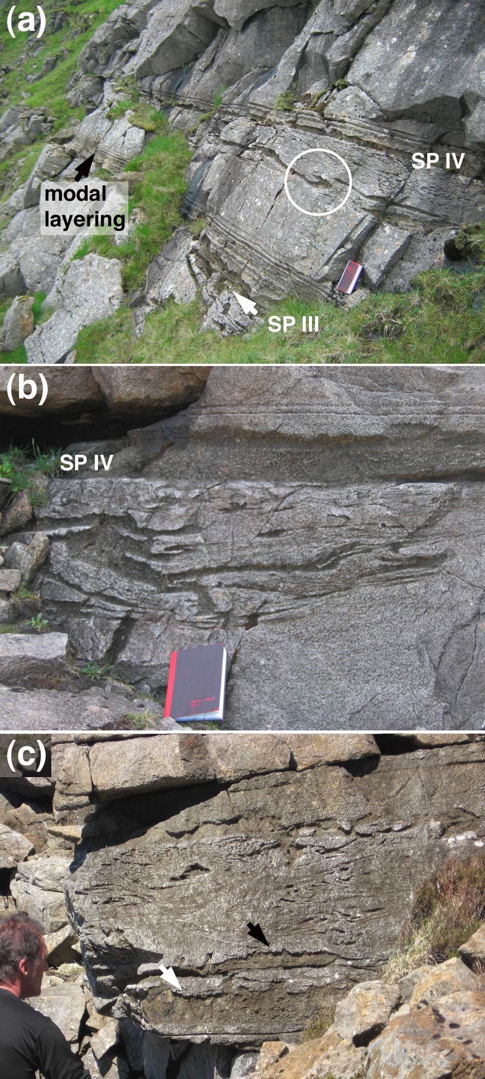
The Unit 12 allivalite is dominated by troctolites, which are commonly foliated. The foliation is defined by a preferred orientation of plagioclase laths or tabular olivines. Poorly defined cross-stratification is locally developed. Rhythmic layering (Irvine, Reference Irvine and Parsons1987), on millimetre to metre scales, is common (Fig. 2a) and includes centimetre- to metre-scale layering graded by either olivine content or grain-size. Bands of almost pure olivine or plagioclase, 1–5 mm thick and commonly anastomosing, occur near the top of the allivalite. In general there is no correlation of centimetre-scale modal, grain size and textural variations in the troctolites between logged traverses, although one set of centimetre-scale modal layers immediately overlying one of the subsidiary peridotite horizons (SP III, see next paragraph) is present throughout the exposure (Fig. 2a).
(a) Subsidiary peridotites III and IV at [GR 39426, 95828]. Note the abundant peridotite wisps and folded lenses below SP IV; the largest of these are at the base of the slumped horizon which overlies uniform laminated troctolite. The folded peridotite slump structure enclosed in the white circle has finger structures developed on the upper surface of both limbs. The notebook is 21 cm long. (b) Close-up of SP IV at [GR 39378, 96469], showing its generally sharply defined and flat base overlying the slumped horizon. Note again the tendency for the largest slumped fragments to lie at the base of the disrupted layer. (c) The slumped horizon beneath SP IV at [GR 39231, 95888]. Note the fingering on the top contact of the larger slumped peridotite fragments (arrowed).

The subsidiary peridotites of the Unit 12 allivalite are indistinguishable from the major peridotite bodies of the Eastern Layered Intrusion, and comprise cumulus olivine with interstitial plagioclase and clinopyroxene (Fig. 2a). The lateral continuity of these horizons is strongly dependent on their thickness: only those whose maximum thickness exceeds 20 cm are laterally continuous on the kilometre scale. The Unit 12 allivalite contains five subsidiary peridotite layers of this magnitude, labelled I–V upwards (Fig. 3). Subsidiary peridotite layer I (SP I, with a maximum thickness ~20 cm) is only seen on Hallival, although the other subsidiary peridotites are found throughout the outcrop of the Unit 12 allivalite.
Isopach maps for the subsidiary peridotites. The dots show the position of the logged profiles.

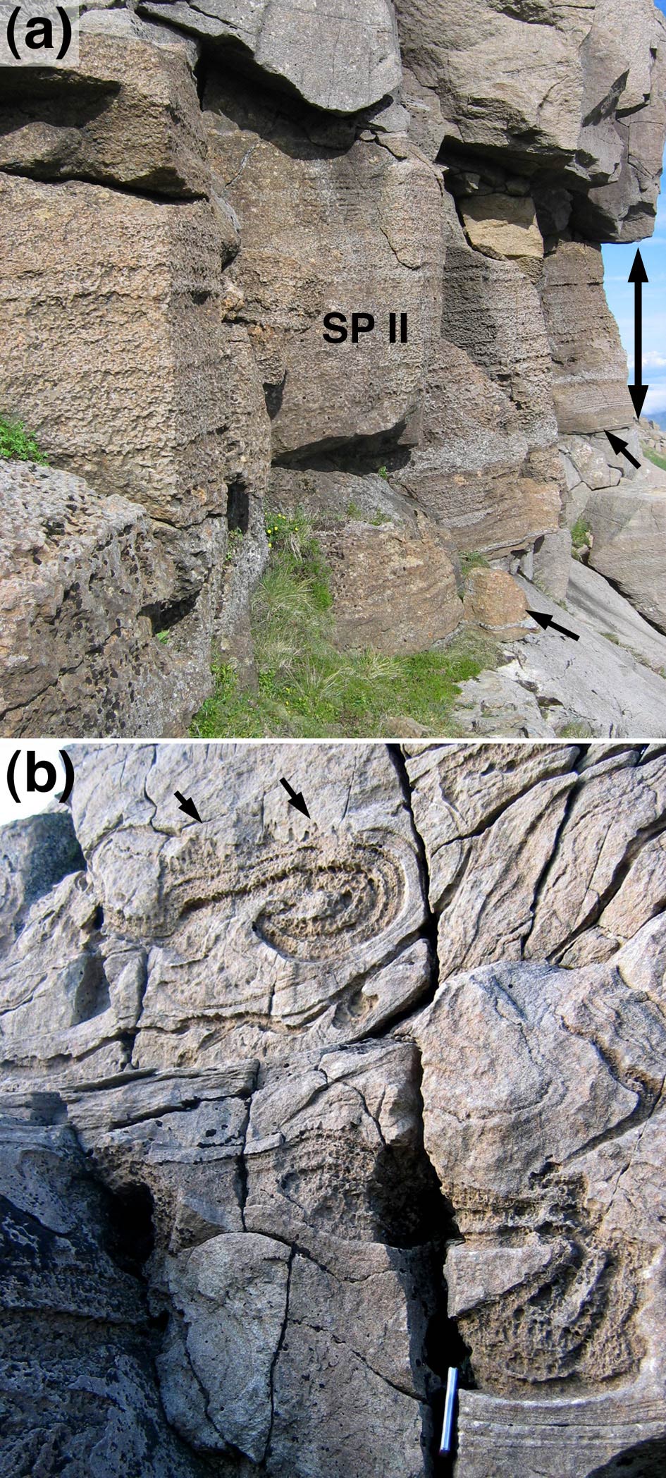
The subsidiary peridotites are divided into two groups based on field observations. SP II ranges from 2.0 to 2.4 m thickness, and thickens to the east (Fig. 3, away from the centre of the chamber). Its base and top are both sharply defined and generally flat (Fig. 4a). Above an olivine-rich basal portion (~30 cm thick), it has well-defined layering picked out by variable amounts of out-weathering plagioclase oikocrysts. A plagioclase-rich horizon, 20–30 cm thick, is commonly present just above the olivine-rich base.
(a) 2.5 m thick SP II at [GR 3928 9494]. The double-ended arrow gives the thickness of the peridotite horizon, while the two single arrows point to the lower contact. Both upper and lower contact are sharp and flat. Note the well-defined compositional banding picked out by variations in the concentration of plagioclase oikocrysts. (b) Compositionally layered swirls of slumped peridotite a few metres below SP III [GR 3931 9493]. Note the well-developed finger structures on the upper edge of the slumps (arrowed). The spine of the notebook is visible at the bottom of the image and is 21 cm long.

Subsidiary peridotites III, IV and V thicken westwards (Fig. 3, towards the intrusion centre) and are no more than 50 cm thick (20–50 cm, 0–20 cm, 0–50 cm, respectively). Subsidiary peridotites IV and V are absent from Profile D, while V is absent from Profiles P, b and d. There is insufficient data to determine the thickening direction for subsidiary peridotite I. All three have olivine-rich bases and SPs III and V are modally layered. None contain the plagioclase oikocrysts characteristic of SP II. Their sharply defined top contacts commonly display features indicative of reactive dissolution of the overlying troctolite, with either elongate vertical protrusions into overlying allivalite (termed ‘finger structures’: Brown, Reference Brown1956; Butcher, Young & Faithfull, Reference Butcher, Young and Faithfull1985; Morse, Owens & Butcher, Reference Morse, Owens and Butcher1987), or more irregular larger-scale replacement features which cut across modal layering in the troctolite (Fig. 2b).
The bases of SP III, IV and V are sharply defined and generally flat, with local undulations (typically with up to ~10 cm amplitude and 50 cm wavelength). Rarely, the base of the peridotite forms tongues extending 5–50 cm into the underlying troctolite. The troctolite underlying peridotites I, III, IV and V contains numerous, multiply-folded, isoclinal or convolute, slumped pods of peridotite commonly displaying high shear strain, indicative of slumping of the cumulate pile (Fig. 2). Some of the slump features are more pod-like, with fingered tops (cf. Butcher, Young & Faithfull, Reference Butcher, Young and Faithfull1985), and the larger may have modal layering defined by variations in out-weathering interstitial plagioclase concentric to the margins (Fig. 4b), which are locally rich in Cr-spinel. The largest slumped fragments occur at the base of the disrupted zone (Fig. 2). The maximum thickness of the slumped region below subsidiary peridotites III, IV and V is about 2 m and is reached in the central outcrops of Unit 12, between the two peaks of Askival and Hallival (in the vicinity of traverses I, J, K, G, O, Q, P and S; Fig. 1b).
Coarse-grained gabbro veins, occasionally with chilled margins, are common, and range from 0.2 mm to ~1 m thick. The thickest occur on southeast Hallival and south Askival. Veins are usually sub-parallel to layering but may cut across layering at all angles. Some, including a 1–5 cm thick vein just above the base of the Unit 13 peridotite on east Askival, and one near the base of the allivalite on east Hallival, are layer-parallel for >200–300 m. These bodies probably represent interstitial melt expelled from underlying compacting cumulates (e.g. Butcher, Reference Butcher1985; Holness, Reference Holness2007).
6. Petrography
6.a. Troctolites
The Unit 12 troctolites contain ~20–50% cumulus olivine (Fo83–87), 50–80% cumulus plagioclase (An83–88), <1% cumulus Cr-spinel, and up to 5 vol.% is intercumulus clinopyroxene (although most troctolites contain <1% pyroxene). Primary magmatic phlogopite is very rare (occurring as thin bands around Cr-spinel grains and within polycrystalline olivine aggregates), although localized and isolated patches of (presumably replacive) brown amphibole, tremolite, calcite and chlorite are present in a few samples. The troctolites are generally very close to end-member adcumulates.
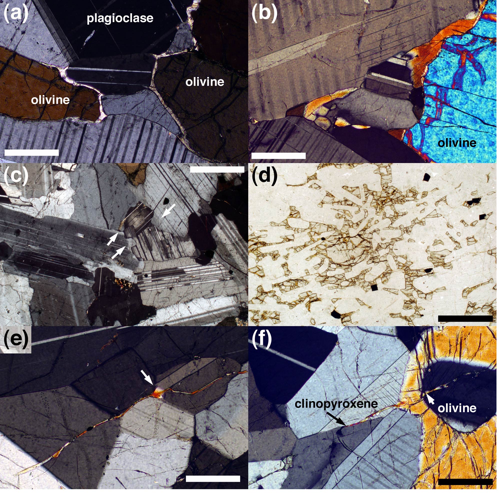
Olivine grains (grain size ~0.5–3 mm) range from subhedral tabular or rounded to anhedral, sometimes with apophyses extending along plagioclase–plagioclase grain boundaries. A variably developed layer-parallel foliation is defined by preferred orientation of tabular olivine and plagioclase crystals (~0.1–1 mm). Bent twins (in plagioclase) and sub-grains (in olivine) record high-temperature, layer-perpendicular compression. Optically visible compositional zoning of plagioclase is generally rare, and plagioclase–plagioclase grain boundaries are smooth, with 120° intersections at triple junctions. Interstitial clinopyroxene forms wedges interstitial to plagioclase grains and thin (<0.1 mm), parallel-sided, monocrystalline rinds on olivine grains (Fig. 5a). Thicker rinds tend to be polygonized (comprising several grains with slightly different lattice orientations), with bulbous (rather than planar) margins (Fig. 5b); there is no spatial pattern of rind thickness relative to stratigraphic height. In olivine-rich troctolites, clinopyroxene may form oikocrysts.
Photomicrographs of Unit 12 troctolites. (a) Monocrystalline rims of clinopyroxene commonly separate cumulus olivine from the surrounding plagioclase. Note the elongate extensions of pyroxene down plagioclase–plagioclase grain boundaries. Profile J. Scale bar is 200 μm long (b) Thick pyroxene rims are commonly polycrystalline. Profile J. Scale bar is 200 μm long. (c) The basal sample from Profile P, showing the strongly normally zoned cumulus plagioclase grains with lobate margins. The arrows show examples of lobes which are enriched in albite. The scale bar is 1 mm long. (d) Sample 14.85 m from the base of Profile P, showing cumulus plagioclase and oikocrysts of olivine. Scale bar is 1 mm long. (e) Sample 6.4 m from the base of Profile J showing trans-granular thin clinopyroxene veins. These veins widen where they cross grain boundaries (arrowed). Scale bar is 200 μm long. (f) Same sample as in (e), showing a vein changing from clinopyroxene to olivine where it crosses a cumulus olivine grain. Scale bar is 200 μm long.

The troctolites from the lower 8 m of Log P (all samples below SP III) are non-foliated orthocumulates containing plagioclase primocrysts with strongly normally-zoned margins and compositionally complex, patchy interiors (Fig. 5c). Plagioclase–plagioclase grain boundaries are irregular, with undulations marked by variation in composition of the feldspar in the concavities (Fig. 5c). Primary magmatic phlogopite is present, together with rare apatite, brown amphibole and interstitial Fe-oxides. Clinopyroxene (which is relatively abundant) is commonly oikocrystic. Pockets of (high-temperature replacive) tremolite, chlorite and serpentine are common. Above SP III the troctolites resemble those of the other traverses, containing optically unzoned plagioclase with smooth grain boundaries, and displaying a progressively stronger foliation with increasing stratigraphic height.
The cumulus assemblage in a single sample from a stratigraphic height of 15 m at Profile P, and another from a similar height at Profile d comprises only plagioclase, with interstitial clinopyroxene and diffuse olivine oikocrysts (Fo82) (Fig. 5d). The absence of similar samples from the other traverses may indicate non-sampling of this horizon rather than its absence.
Troctolites from Profile J locally contain rare, thin (5–10 μm), clinopyroxene films and strings of isolated, optically continuous, lenses on plagioclase–plagioclase grain boundaries. Some thin films cut through plagioclase grains (Fig. 5e), commonly widening where they encounter plagioclase–plagioclase grain boundaries (Fig. 5e). Where the veins cross cumulus olivine grains, they are replaced by strings of tiny inclusions, with the further continuation of the vein on the other side marked either by clinopyroxene or by an elongate extension of the cumulus olivine grain (Fig. 5f). Some of these samples also contain thin (10–50 μm) late-stage, cross-cutting veins marked by phlogopite, clinopyroxene, calcite and albitic plagioclase (~Ab50).
6.b. Peridotites
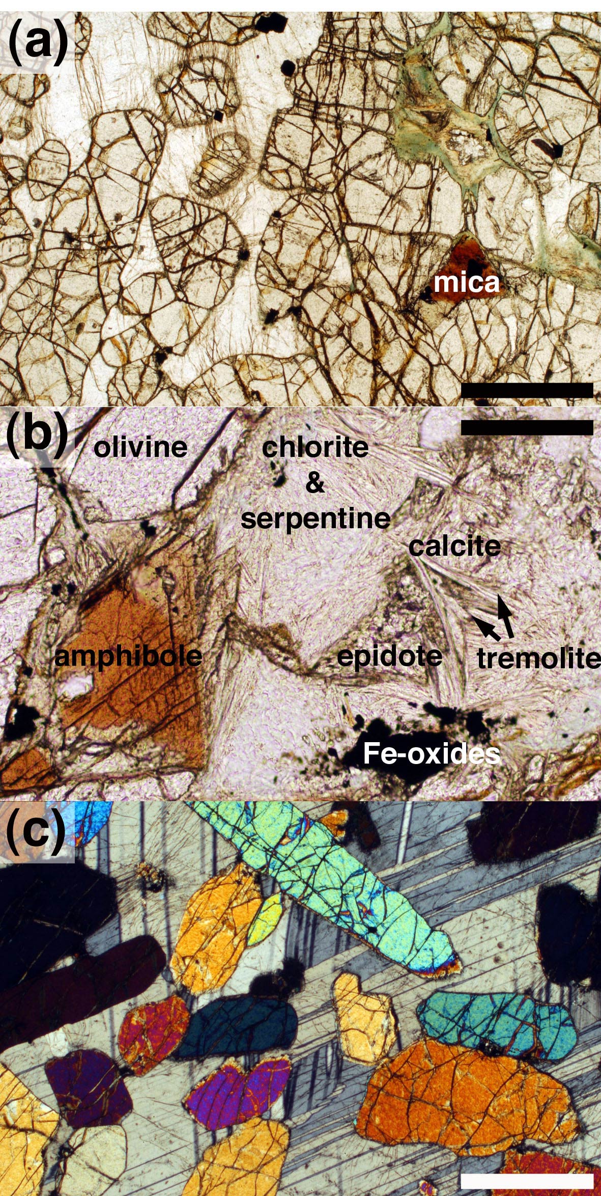
The peridotite layers are dominated by sub-rounded to tabular cumulus olivine, with minor cumulus Cr-spinel, with interstitial plagioclase and subordinate clinopyroxene (Fig. 6a). They are far from adcumulates; interstitial plagioclase in olivine-rich regions commonly has normally zoned margins and primary magmatic phlogopite is common (Fig. 6a). The latter occurs in interstitial pockets in regions where the olivine grains are closely spaced. These pockets are commonly concentrically zoned, with an outer rim of intergrown chlorite and serpentine replacing cumulus olivine, and an inner shell of green pleochroic chlorite. Epidote, tremolite and calcite may be present in the centre of the pockets (Fig. 6b) in addition to the phlogopite, with irregular grains of Fe-oxides and rare euhedral (presumed primary magmatic) apatite.
Photomicrographs of Unit 12 subsidiary peridotites. (a) Sample of SP II from Profile D, showing rounded olivine cumulus grains set in interstitial plagioclase. Note how the primary hydrous mica (phlogopite) is confined to olivine-rich areas. Scale bar is 200 μm long. (b) Sample of SP IV from Profile d, showing hydrous minerals concentrated into a pocket between olivine grains (only one is shown). Scale bar is 200 μm long. (c) Sample of SP II from Profile J, showing randomly oriented and widely spaced cumulus olivine grains set in a plagioclase oikocryst. Scale bar is 200 μm long.

While the thinner subsidiary peridotites have a fine poly-crystalline matrix of interstitial plagioclase and pyroxene, SP II has an oikocrystic matrix in which widely spaced, non-oriented olivine grains of widely varying shapes and aspect ratios are enclosed by plagioclase, and (to a lesser extent) clinopyroxene, oikocrysts (Fig. 6c). Between the oikocrysts, where the interstitial plagioclase and clinopyroxene are finer-grained, the olivine grains are more closely spaced, although with a similar grain size to the olivine enclosed by the oikocrysts.
6.c. Dihedral angles
Median clinopyroxene–plagioclase–plagioclase dihedral angles, Θcpp, measured through the allivalite at logs D, J and P are shown in Figure 7, together with previously published data for Unit 12 (Holness, Reference Holness2007), supplemented by new samples collected from the contacts of the minor peridotites. Locations of minor peridotites are marked, as well as the ‘normal’ range of dihedral angle expected for Rum troctolites (Holness, Nielsen & Tegner, Reference Holness, Hallworth, Woods and Sides2007).
Median clinopyroxene–plagioclase–plagioclase dihedral angles, Θcpp, in the Unit 12 troctolites as a function of stratigraphic height. The subsidiary peridotites are marked by the vertical grey boxes, while the horizontal grey box gives an indication of the expected range of median angles for an undisturbed troctolitic cumulate in the Rum chamber. The open circle at the base of Profile P gives the median of a sample for which only ten measurements were made. All other data points are the median of populations of 30–60 angles.

Most of the samples fall within the expected range of Θcpp. Median Θcpp values in Profile J are generally lower than expected in many of the samples from the lowermost 9 m of the section. Dihedral angles fall within the expected range at the contacts with SP II. Θcpp is elevated above the expected value within a few centimetres of the base of SP III. There is a localized negative excursion in the troctolite between SP III and SP IV in Profiles J and P, consistent with that already reported for Profiles b and d (Holness, Reference Holness2007). Θcpp does not vary from the expected value in the vicinity of SP IV, even for samples directly at the lower and upper contacts, apart from a single sample within 1 cm of the base at Profile b. SP V is only present at Profile J, and here the angles increase within 70 cm of the base and are anomalously low above the top contact. A small positive excursion occurs within ~10 cm of the Unit 12/13 contact.
7. Geochemistry
7.a. Sr isotopes
Palacz (Reference Palacz1985) presented a comprehensive Sr isotope study of the Eastern Layered Intrusion, including 86Sr–87Sr ratios for Unit 12 in the vicinity of Profile d. He sampled SPs II and III although not IV. These data, with stratigraphic heights measured from the base of the Unit 12 allivalite, are shown in Figure 8. The Sr isotope composition for Unit 12 varies from 0.7041 to 0.7055, which Palacz (Reference Palacz1985) interprets as indicative of mixing of isotopically distinct magmas. He suggests that increases in 87Sr/86Sr from the primary mantle signature of 0.70355 were caused by contamination by upper crustal Lewisian amphibolite-facies gneisses. The isotopic variability within Unit 12 demonstrates that the chamber was not closed during this time, with multiple replenishments of variably contaminated magmas.
Strontium isotope ratios of bulk rock samples of Units 12 and 13, taken from Palacz (Reference Palacz1985). Grey shaded regions denote peridotite. The errors on the ratios (reported by Palacz, Reference Palacz1985) are of the order of the spot size.

7.b. Olivine
In agreement with previous studies (Tait, Reference Tait1985; Renner & Palacz, Reference Renner and Palacz1987), we found no Fe/Mg zoning, although Ca content is slightly higher in the centres of some grains. Olivine compositions are shown as a function of stratigraphic height in Figure 9 (Appendix Table A1, available as supplementary material online at http://journals.cambridge.org/geo). The data have been normalized to the stratigraphic heights of Profile J (by stretching the heights between the subsidiary peridotites) to permit direct comparison. The three new profiles are very similar, with Profile P containing the most Fe-rich, and Profile J the most Mg-rich olivines (Fig. 9a). Profile J is indistinguishable from the previously published data from Profile d, while Profile b is significantly more Mg-rich than the others. The two troctolite samples with oikocrystic olivine have relatively low Mg/Fe ratios. The Fo content of the olivine in the subsidiary peridotites and in slumped pods of peridotite is indistinguishable from that in the troctolites.
Olivine compositions as a function of stratigraphic height, with (a) forsterite content and (b) Ni content. The different traverses have been normalized to the stratigraphic heights of Profile J, using the positions of the subsidiary peridotites as anchor points. Between the peridotites, the data from the troctolites have been stretched to fit. Note that SP V is only observed in Profile J. While the top and bottom of Profiles D, J and P are sampled, the base of neither b nor d is exposed. Profile b was placed in the normalized sequence by assuming that the base of SP III occurs at the same stratigraphic height as that in J, and simply plotting on the samples below SP III directly. Profile d was plotted in a similar manner, assuming that the base of SP II coincides in d and J.

Variation in Ni content is similar in all five profiles, apart from a consistently higher Ni content in the olivines from Profile b (Fig. 9b). While there are minor differences in the trend of Fo, the Ni data are consistent between the profiles, with an initial decrease below SP II, followed by a consistently high Ni between SPs II and IV, with a monotonic decrease to SP V. Ni content increases slightly above SP V.
7.c. Plagioclase
Plagioclase compositions are shown as a function of stratigraphic height (normalized to Profile J) in Figure 10a (and reported fully in Appendix Table A2, available as supplementary material online at http://journals.cambridge.org/geo). The composition of the central regions of plagioclase grains within a single troctolitic sample varies by ~2–3 mol.% anorthite, and there is no compositional variation with stratigraphic height. Plagioclase compositions in the troctolites of Profiles P (the central parts of the grains) and D are both in the range An81–88. The plagioclase in the Profile J troctolites is slightly more anorthitic (An84–88). The margins of (normally zoned) plagioclase grains in the lower parts of Profile P reach An63; the most albitic margins are those immediately adjacent to interstitial clinopyroxene.
(a) Plagioclase compositions (centres of grains) as a function of stratigraphic height, normalized to Profile J (see caption to Fig. 9 for details of normalization). Legend is given in Figure 9. The low anorthite contents of Profile P samples at 0.9, 2.8 and 5.7 m were measured on the rims of cumulus grains. The low analyses in Profile b samples below SP III were measured in peridotite from the slumped horizon. (b) The central parts of plagioclase grains measured in samples containing both peridotite and troctolite (that is, from the contacts with subsidiary peridotites or from samples containing peridotite slumps). Note that plagioclase in the peridotite is generally more albitic than that in the immediately adjacent troctolite.

The composition of the central parts of interstitial plagioclase grains in the subsidiary peridotites and in the slumped fragments tends to be more albitic than the central regions of plagioclase in the troctolites (Fig. 10b). This difference is established on a thin-section scale within 1 cm of the contact between troctolite and peridotite.
7.d. Clinopyroxene
The clinopyroxene is diopsidic with Mg numbers in the range 84–90 (compositional data reported in Appendix Table A3, available as supplementary material online at http://journals.cambridge.org/geo). The highest values of Mg number occur in the pyroxenes of Profile J, while the lowest are found in Profile P. The Mg number of clinopyroxene in the subsidiary peridotites is indistinguishable from that in the troctolite. There is a good correlation between the average Fo content of olivine and average Mg number of clinopyroxene (Fig. 11a). There is no apparent variation of composition with height.
(a) Average Mg number of interstitial clinopyroxene compared with the average forsterite content of coexisting cumulus olivine. Each dot represents a sample of Unit 12 troctolite. (b) Cr2O3 content of interstitial clinopyroxene plotted as a function of Mg number. See Figure 9 for the legend, although in this case the open circles denote peridotite samples. The grey circles denote the compositions of the thin clinopyroxene veins from Profile J shown in Figure 5e and f. The stratigraphic positions of the six vein-bearing samples from which these analyses were obtained are shown in the inset diagram in which the subsidiary peridotites are shown as shaded boxes.

Clinopyroxene forming thin veins and small isolated grains on plagioclase grain boundaries in Profile J (Fig. 5e, f) generally has low Cr2O3, while Mg number varies from 90 to 77 (Fig. 11b). Other major and minor element contents are similar to those of clinopyroxene forming larger grains.
8. Discussion
8.a. Comparison of mineral compositions with other units of the Eastern Layered Intrusion
The mineral compositions for the Unit 12 troctolites reported here are consistent with previously published data, with higher Mg/Fe ratios of olivine and clinopyroxene than in the gabbroic allivalites of Unit 8/9 (Holness, Reference Holness2007) and the transitional Unit 10 allivalite (which has cumulus olivine and plagioclase throughout, but only locally developed cumulus clinopyroxene: Tait, Reference Tait1985; Brown, Reference Brown1956), but similar Mg/Fe ratios to the troctolitic Unit 14 allivalite (Renner & Palacz, Reference Renner and Palacz1987). The central regions of plagioclase grains in the Unit 12 troctolites are more anorthitic than those of the gabbroic Unit 8/9 allivalite (Holness et al. Reference Holness, Hallworth, Woods and Sides2007) and similar to those of the troctolitic Unit 14 allivalite (Renner & Palacz, Reference Renner and Palacz1987). These compositional variations are consistent with a similar parental magma and liquid line of descent for the allivalites of the upper parts of the Eastern Layered Intrusion.
The absence of compositional (Mg/Fe) zoning in the olivines of the Eastern Layered Intrusion and the good correlation with the Mg number of associated interstitial pyroxene supports previous suggestions that Mg/Fe ratios have been extensively diffusionally modified and cannot be used as a reliable indicator of magma chamber processes (Emeleus et al. Reference Emeleus, Cheadle, Hunter, Upton, Wadsworth and Cawthorn1996). In particular, the similarity of Mg/Fe ratios of olivine in the subsidiary peridotites and their surrounding troctolites is likely to be a consequence of diffusional modification. However, Ni contents are less likely to have been modified (Tait, Reference Tait1985; Renner & Palacz, Reference Renner and Palacz1987), and the absence of significant differences in Ni content between the subsidiary peridotites and their host troctolites is consistent with only a small original compositional difference of the olivine. The small cryptic reversals found by Faithfull (Reference Faithfull1985), associated with subsidiary peridotites of Units 1–5, are likely to be a consequence of a significant original compositional difference, since olivines in the allivalites of these relatively evolved lower units have forsterite contents as low as 71%.
8.b. Replenishment events in Unit 12
Palacz's (Reference Palacz1985) Sr isotope data (Fig. 8) demonstrate that Unit 12 formed from a complex series of magma replenishment events. The 87Sr–86Sr ratio of the Unit 12 peridotite increases from 0.7045 to 0.7055, consistent with an increasing degree of contamination. This could be accounted for either by progressive contamination of a single batch of picrite within the Rum chamber, or by the addition of batches of increasingly contaminated magma. The base of the Unit 12 allivalite corresponds to a drop in 87Sr/86Sr, signifying the arrival of a batch of evolved, relatively uncontaminated magma saturated in olivine and plagioclase. Both SP II and SP III have higher 87Sr/86Sr than the surrounding troctolite, demonstrating that they formed from batches of relatively contaminated picrite. The similarity of the isotope composition of the two subsidiary peridotites suggests they might have had the same source.
The relatively small drop in 87Sr/86Sr from SP II to the immediately overlying troctolite suggests mixing with the resident basalt of a relatively large batch of contaminated picrite (cf. Huppert & Sparks, Reference Huppert and Sparks1980), consistent with the step-wise increase in Ni content in olivine at this level (the difference between regions 1 and 2 in Fig. 9b). In contrast, the large drop in 87Sr/86Sr between SP III and the immediately overlying troctolite suggests the arrival in the chamber of fresh, relatively uncontaminated basalt (with an isotopic composition, and major element composition (recorded in the high Ni content in olivine in region 3, Fig. 9b), similar to that of the batch which marks the base of the Unit 12 allivalite). Towards the top of Unit 12 the resident basaltic magma became slightly contaminated, while the base of Unit 13 signifies the arrival of a major batch of relatively uncontaminated picrite. Although we do not have data for SP IV (which is exposed at Palacz's sample site but was not sampled) or SP V (which is not exposed at Palacz's sample site), it is entirely plausible that both these subsidiary peridotites also represent influxes of picrite magma into the chamber.
The distinctive horizon containing interstitial olivine, sampled in Profiles d and P, is further evidence for an input of magma at this level in the stratigraphy. This magma, saturated only in plagioclase, is very different to the usual magmas of the Eastern Layered Intrusion which all saturate in olivine before plagioclase arrives on the liquidus.
The dihedral angle data support picrite replenishment events as the source of the subsidiary peridotites. Median Θcpp is high in the troctolite immediately underlying SP III, IV (locally) and V, similar to the anomalously high values seen under the major peridotite horizons (Holness, Reference Holness2005), consistent with the arrival of a layer of hot primitive magma. There is no thermal signature beneath SP II, despite the isotopic evidence for it forming from an influx of picrite. There are no anomalously high median Θcpp values at the base of the Unit 12 allivalite corresponding to the suggested influx of basaltic magma (Fig. 7), in contrast to Unit 14 (Holness, Nielsen & Tegner, Reference Holness, Nielsen and Tegner2007), but the mixing of a large quantity of basalt into liquid saturated only in olivine would not have raised the temperature. The drop in 87Sr/86Sr above SP III (Fig. 8), which may represent an influx of relatively uncontaminated basaltic magma, corresponds with a chamber-wide region of anomalously low Θcpp (Fig. 7).
Holness (Reference Holness2007) suggested the anomalously low values of Θcpp between SPs III and IV are the result of a transiently increased cooling rate caused by the arrival of a cool crystal-laden current from the chamber roof, possibly associated with tectonic activity. Part of the basis for her arguments is the difference in olivine composition between Profiles b and d above SP IV. Our enlarged dataset (Fig. 9a) shows this divergence of composition is neither unusual nor significant. Instead, it is possible that the low angles were caused by the arrival of a batch of relatively cool magma. Normal conditions then resumed after the arrival of the picrite which formed SP IV. While this explanation is beguiling, olivine and plagioclase compositions do not show an excursion to more evolved compositions between SPs III and IV (Figs 9, 10); the nature of this chamber-wide thermal excursion remains unc lear.
8.c. The slumped horizons
SPs I, III, IV and V are underlain by a significant thickness of troctolite containing disrupted and convoluted peridotite inclusions. These slumped horizons are evidence for a steeply inclined chamber floor at the time of these minor picrite replenishment events, and are not consistent with a sill-like origin for this group of subsidiary peridotites (cf. Morse, Owens & Butcher, Reference Morse, Owens and Butcher1987). The presence of several generations of isoclinal folds in peridotite pods some metres below the top of the slumped horizon is compatible with the slumped horizons forming during down-slope sliding of unconsolidated cumulates, rather than as a result of magmatic currents which are unlikely to generate such high strains a metre or more below the top of the mush. The coherent nature of the peridotite slumps, with their chemically distinct interstitial plagioclase and sharp contacts commonly bearing concentrations of Cr-spinel, suggests they formed by the physical disruption of a partially crystalline, and physically coherent, olivine cumulate horizon overlying a significant thickness of unconsolidated troctolitic cumulate (although the thickness of the slumped horizon provides only a minimum estimate for the thickness of this unconsolidated mush). The largest coherent blocks of the peridotite moved to the base of the slumped horizon during the physical disruption of the modally stratified mush.
Slumped horizons only occur beneath subsidiary peridotites which thicken to the west. We suggest SPs I, III, IV and V formed from a small influx of picrite entering the chamber from the Long Loch fault zone and flowing over a sloping, poorly consolidated but essentially planar, chamber floor, underneath the resident evolved magma. The cooling picrite formed a layer of dense olivine cumulates overlying the troctolitic mush. The magma-static pressure driving the influx was likely to have been small and associated with periodic withdrawal of the magma, precipitating slope failure partway through the formation of the subsidiary peridotite (e.g. Emeleus et al. Reference Emeleus, Cheadle, Hunter, Upton, Wadsworth and Cawthorn1996). Note that this model precludes peridotite accumulation via slumped material from the walls and roof since the bulk of the chamber is filled by liquid saturated in both olivine and plagioclase.
8.d. Fingering
Peridotite slumped enclaves (Figs 2c, 4b) and gravitational load structures (Butcher, Young & Faithfull, Reference Butcher, Young and Faithfull1985) commonly have fingered tops. The fingers cut fabrics and modal layering in the troctolite (e.g. Faithfull, Reference Faithfull1985), demonstrating that the fingers post-date troctolite deposition (although not proving that they post-date complete troctolite solidification). The development of fingering on even small peridotite enclaves demonstrates that it is unlikely that their formation involved a significantly hotter peridotite relative to the host troctolite, as advocated by Morse, Owens & Butcher (Reference Morse, Owens and Butcher1987). Their presence on the tops of (presumed) discrete and isolated peridotite inclusions also demonstrates that through-flow in sills was not required for their formation.
The abundant primary magmatic hydrous minerals in the subsidiary peridotites attest to the retention of abundant, evolved, H2O-rich liquid in the later stages of solidification. The fingers themselves also contain primary hydrous minerals (Butcher, Young & Faithfull, Reference Butcher, Young and Faithfull1985). Since the addition of H2O not only reduces solidus temperatures but also enlarges the primary phase field of olivine (Yoder, Reference Yoder1973; Kushiro, Reference Kushiro1972), the addition of H2O to an essentially dry interstitial liquid saturated in olivine, plagioclase and clinopyroxene will result in the resorption of plagioclase and pyroxene. We therefore suggest that the fingering results from the upwards expulsion of relatively H2O-rich interstitial liquid from a physically coherent, thermally equilibrated, olivine cumulate mush.
8.e. The thickness of the magma lens
Fractionation caused by crystal settling on the chamber floor results in a progressive change in primocryst composition (and ultimately in the primocryst assemblage). The rate of change of primocryst composition in the cumulates reflects the thickness of the magma lens, which itself is a complex function of cooling rate, replenishment and eruption. Significant Mg/Fe exchange in the cumulate pile precludes the use of forsterite content in olivine, but the olivine Ni content is unlikely to have been significantly modified post-accumulation and can be used to track the changing thickness of the magma lens: the thinner the magma lens, the more rapidly Ni in olivine should decrease with height in the cumulate pile.
Ni in olivine reduces from an average of 2100 ppm to 1700 ppm below SP II (region 1 in Fig. 9b). Between SPs II and III (region 2) the average is constant at ~1900 ppm. Above SP III (region 3) the average is constant at ~2000 ppm, while above SP IV (region 4), it reduces from ~2000pm to ~1600 ppm. The magma lens in regions 1 and 4 was therefore thin relative to its size in regions 2 and 3. An estimate of the thickness of the magma lens in regions 1 and 4 was made using the program MELTS (Ghiorso & Sack, Reference Ghiorso and Sack1995; Asimow & Ghiorso, Reference Asimow and Ghiorso1998). Fractionation of olivine and plagioclase occurs in the temperature range 1190–1175°C from a bulk liquid corresponding to the picrite dyke B65 (J. E. McClurg, unpub. Ph.D. thesis, Univ. Edinburgh, 1982) at 200 bars (cf. Holness, Reference Holness1999) and oxygen fugacity of QFM (following Upton et al. Reference Upton, Skovgaard, McClurg, Kirstein, Cheadle, Emeleus, Wadsworth and Fallick2002). Removal of approximately 10% by volume of the liquid results in the reduction in olivine Ni content from ~2000 ppm to ~1500 ppm. Since these reductions in Ni occur over 3 and 4 m of stratigraphy in regions 1 and 4, respectively, the magma lens during these periods must have been of the order of 30–40 m thick. It is not possible to constrain the thickness of the lens in regions 2 and 3, but the absence of significant change in olivine Ni content points to a thickness much greater than 40 m.
8.f. Subsidiary peridotite II
SP II differs in many ways from the other four subsidiary peridotites: it has no thermal signature; it has well-defined layering of the interstitial phases and a distinctive oikocrystic texture everywhere; it only very rarely has a fingered top; it does not overlie a slumped horizon; it is much thicker; and it thickens to the east.
The greater thickness points to SP II being generated from a larger than usual influx of picrite compared to the other subsidiary peridotites, presumably injected into the chamber with a high magma-static pressure, thus avoiding draw-back and slumping, and forming a discrete layer under the resident basalt. The magma chamber floor may also have been less strongly dipping towards the Central Complex at Long Loch. The size of the magma batch was large enough to affect the Sr isotopic composition of the resident basaltic magma once the picrite layer had evolved sufficiently to trigger overturn and mixing (Fig. 8) and to re-set the composition of the resident magma so that it produced relatively Ni-rich olivine, and to slow down the rate of change of olivine Ni content with stratigraphic height (Fig. 9b).
The absence of fingering above SP II suggests only minor expulsion of interstitial liquid. Poikilitic plagioclase in SP II encloses widely spaced, randomly oriented, olivine grains, while the late-stage hydrous minerals are concentrated in the olivine-rich material between oikocrysts. These observations are consistent with plagioclase nucleation pre-dating compaction. If SP II solidified before compaction this would retain interstitial liquid and reduce the amount of alteration of the overlying troctolite. The absence of a thermal signature is consistent with early plagioclase nucleation: the picrite was very close to plagioclase saturation when injected into the chamber and thus not significantly hotter than the resident magma.
The thickening towards the east may have been the result of a significant input of olivine crystals from the chamber walls (e.g. Tepley & Davidson, Reference Tepley and Davidson2003). This would be possible for picrite layers sufficiently thick to create a zone of primary olivine crystallization on the walls, but not for thin picrite layers.
8.g. Infiltration events
The low median Θcpp values in the basal 3 m of Profile J (below SP II) are associated with elongate pyroxene extensions down plagioclase–plagioclase grain boundaries (Fig. 5a), which have been attributed to late-stage melt infiltration (Holness, Reference Holness2007). However, although forsterite contents of olivine in the basal few metres of Profile J are elevated relative to Profiles D and P (Fig. 9a), they are similar to those at the base of Profile d (which does not show anomalous Θcpp), and there is no anomalous Ni signature (Fig. 9b). The absence of a compositional signature of infiltration in the olivine suggests that this event involved only small volumes of melt. The anomalously low Θcpp above SP V may have been caused by late-stage infiltration of troctolite by interstitial liquids from the subsidiary peridotite.
The thin clinopyroxene-bearing veins in Profile J are a late feature, as evidenced by the associated phlogopite, calcite and albitic plagioclase. The source of the liquids is unclear. The absence of any compositional relationship with the subsidiary peridotites (Fig. 11b) rules these out as a possible source. They may be exceptionally thin versions of the late-stage veins described by Butcher (Reference Butcher1985), although he did not give details of clinopyroxene composition.
9. Conclusions
Piecing together the field, geochemical and textural evidence demonstrates that the Unit 12 allivalite is a complex cumulate body built up on the floor of a silllike magma chamber undergoing a series of replenishment events (Fig. 12). The thickness of the magma lens varied considerably during the formation of the Unit 12 allivalite, reflecting periodic replenishment and eruption. A significant reduction in lens thickness above SP IV suggests that the arrival of this batch of picrite triggered an eruption. The replenishing magmas varied in composition from picrite through to basalt and had undergone variable degrees of crustal contamination: the picrites were generally more contaminated than the basalts in contrast to the more common picture of pristine picrite becoming contaminated within the Rum chamber itself (Palacz, Reference Palacz1985).
Summary of the events recorded by the Unit 12 allivalite.

In a similar fashion to Unit 14, the onset of troctolite formation in Unit 12 appears to have been the result of an influx of evolved magma (from the data of Palacz, Reference Palacz1985). The allivalites of both units also record evidence for multiple replenishment events. On the basis of detailed studies of only two units (and of those only the allivalites), we tentatively suggest that the Eastern Layered Intrusion was built of a multitude of relatively small magma batches of variable composition, sourced from a series of deeper chambers. The major macro-unit scale divisions are thus due more to the stochastic nature of the replenishment process, rather than to the arrival and subsequent fractionation of large batches of (essentially primary) picrite. We note that this new view of the Eastern Layered Intrusion is a direct corollary of the chamber being sill-like (Emeleus et al. Reference Emeleus, Cheadle, Hunter, Upton, Wadsworth and Cawthorn1996) rather than of the order of 1 km deep (Tait, Reference Tait1985).
Acknowledgements
BW's fieldwork was supported by Clare College and the initial work on the project was done for his undergraduate final year thesis at the Department of Earth Sciences, University of Cambridge. We are grateful to Scottish Natural Heritage for permission to work and sample on Rum. Rachel Sides and Mark Hallworth are thanked for field assistance, and Nigel Woodcock provided valuable insights into the nature of the slumped horizons.