1. Introduction
Compared with wheeled robots, biped robots can better adapt to rugged environments, such as gullies and stairs. Robots will help people repeat boring tasks after increasing the ability of dexterous operation [Reference Namiki and Yokosawa1]. Therefore, people hope bipedal robots can enter working environments to help them complete dangerous tasks or explore isolated areas [Reference Chen, Yu, Zhang, Zheng, Huang and Ming2–Reference Fukuda5]. The Atlas robot from Boston dynamics has become a famous representative of the application of robotics in engineering [6]. However, public information on how its algorithm works is still lacking. The motion planning and control algorithm of biped robots has been widely discussed in recent years [Reference Liu, Yang, An, Liu and Chen7, Reference Kim, Zhao, Thomas, Fernandez and Sentis8]. Currently, very few biped robots can move dynamically and stably outdoors [Reference Siekmann, Green and Warila9–Reference Da, Hartley and Grizzle11]. One of the critical influencing factors is that dynamic motion planning and trajectory correction significantly impact environmental adaptability. For instance, in a complex environment, it is sometimes necessary for the robot to adjust the support height to proceed, adjust the step frequency to maintain stability, or adjust the foot lifting height to avoid a collision. Therefore, when facing a complex dynamic environment, the robot’s dynamic modified gait plays an important role in its balance and stability. In general, the existing algorithms, which can be divided into model-based and model-free algorithms, have some limitations in dynamically adjusting the above parameters.
The principle of the model-based method is to consider the dynamic characteristics of a model and let the biped robot simulate this model to generate a state sequence. The most famous model-based approach is the gait generator based on the linear inverted pendulum (LIP) [Reference Kajita, Kanehiro and Kaneko12, Reference Luo, Su, Ruan, Zhao, Kim, Sentis and Fu13], which has a constant height of the center of mass (CoM). By simplifying the biped robot into an LIP and planning the zero moment point (ZMP) trajectory, the CoM trajectory is then obtained. Later, to control the unstable divergent state, the divergent components of motion method was proposed, and experiments were successfully carried out on several robots [Reference Mesesan, Englsberger and Garofalo14]. However, when these methods resist disturbance, compliance controls need to be added to stabilize themselves [Reference Pi, Kang, Xu, Li and Li15]. Application scenarios are limited to flat indoor surfaces ground. Xiong and Ames proposed the hybrid-LIP model to introduce the two-foot support period [Reference Xiong and Ames16] so that the underactuated biped robot (UBR) can achieve the stability even with significant disturbances. Similarly, the spring-loaded inverted pendulum model is also used [Reference Xiong and Ames17]. However, using these simplified models results in the algorithm requiring the robot centroid to considerably upwards [Reference Dadashzadeh and Macnab18], which is challenging to satisfy this requirement for some biped robots due to their ability needs. With the development of nonlinear optimization in trajectory planning, trajectory optimization based on the whole-body model of a biped robot has been studied [Reference Hereid, Harib, Hartley, Gong and Grizzle19, Reference Hobon, De-León-Gómez, Abba, Aoustin and Chevallereau20]. In this method, a dynamic model of the biped robot’s entire body is established, the motion library is generated by offline optimization, and the desired action is realized by real-time control. However, for a biped robot with more than 10 or 20 degrees of freedom (DoFs), optimization will consume a lot of time and is also sensitive to the initial state [Reference Drnach and Zhao21–Reference Grizzle, Christine and Shih23]. In addition, the offline gait library will have limitations for the environment that has not been established. More importantly, due to the property constraints of the model itself, changing parameters online such as walking cycle and height will cause model mismatch. Therefore, model-based trajectory planning has some limitations in real-time variable parameters.
The essence of the model-free method is to generate actions through heuristic strategies. The famous representative of this method is the set of three strategies used by Raibert to control hopping robots [Reference Raibert24]. This method relies on the robot’s swing and then cooperates with the upper body attitude control and foothold control to realize the movement of legged robots. This strategy is still used in the Atlas robot [Reference Nelson, Saunders, Playter, Goswami and Vadakkepat25]. It also significantly impacts the dynamic motion planning and control of biped robots [Reference Han, Chen, Yu, Zhu, Hashimoto and Huang26, Reference Han, Chen, Yu, Gao, Huang and Huang27]. Nonmodel-based trajectory planning can use fewer parameters to form rich gait motion. Yin et al. [Reference Yin, Kevin and Michiel28] proposed the SIMBICON method to realize the animation simulation of multiple actions of the robot by giving a particular joint state but did not consider the robot performance and dynamic model. Recently, artificial intelligence learning algorithm has made remarkable progress in the robotics field [Reference Qi and Su29, Reference Su, Hu, Karimi, Knoll, Ferrigno and De Momi30]. This kind of method mainly involves setting heuristic rewards so that the robot can constantly make attempts and make mistakes to obtain the policy that generates the proper trajectory [Reference Li, Cheng, Peng, Abbeel, Levine, Berseth and Sreenath31]. Relevant research focuses on Cassie and Digit robots with good performance and shows unexpected results of experiments in real environments [Reference Siekmann, Green and Warila9, Reference Krishna, Castillo, Mishra, Hereid and Kolathaya32]. However, such research is still in the preliminary stage, and the high requirements for drivers and mechanical structure make it difficult to promote and popularize it. The biped robot completes the walking action by the heuristic method easily and quickly, but there is no unified framework for model-free motion planning including multiple gait parameters.
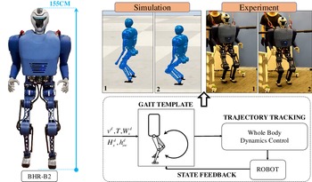
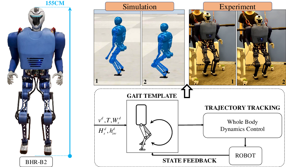
Therefore, to solve the problem that the gait parameters cannot be modified in real time to adapt to changing environments, we propose a heuristic model-free gait template for walking planning and control to establish a unified mathematical framework (as shown in Fig. 1). It consists of the following contributions.
-
(1) The gait template does not depend on the model, which integrates gait parameters such as support height, walking cycle, foot lifting height, and walking speed to form a specific mathematical expression, which is convenient for biped robots to generate walking trajectories.
-
(2) The gait template allows online trajectory generation and real-time correction and realizes the robot’s motion following through whole-body dynamics control (WBC), which is conducive to the improvement of dynamic environment adaptability.
-
(3) A large biped robot with integrated structure is developed, and the feasibility and effectiveness of the algorithm are verified on the robot.
The rest of this paper is arranged as follows: Section 2 introduces the design process of the gait template in detail. Section 3 shows the control method for realizing the gait trajectory. Section 4 presents the analysis of experiments and simulations, and Section 5 is a summary and discussion.
The BHR-B2 robot uses the trajectory generated by the gait template to move in the simulated environment and the experiment with dynamic motion control. On the left is the robot experimental platform. The total height of the robot is 155 cm.
2. Gait template
2.1. Walking trajectory design
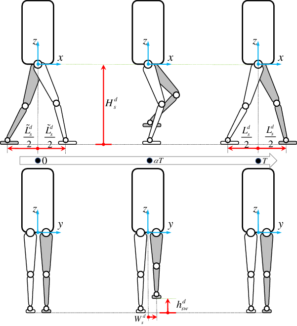
Inspired by natural human motion, we used a heuristic strategy to plan the movement of both legs. Because the period of time in which both legs are supporting weight during walking is small, that period of time is ignored by the gait template. We only consider the stage of alternating left and right supporting legs. We define one step as follows: the process of the leg from contact with the ground to swinging in the air and then contact with the environment. Figure 2 shows the movement of both legs during one step. Within each step, one leg must get to the ground, called the support leg (white color-filled) marked
 $s$
, while the other leg completes the leg lifting and stepping down in the air to become a swing leg (gray color-filled) marked
 $sw$
. Next, leg trajectory planning is described in detail.
Diagram of walking gait template. One-step action decomposition of the robot in the sagittal and coronal planes. The walking cycle is divided into two stages: raising the foot and stepping down.

As shown in Fig. 2, define the coordinate system
 $xyz$
at the center of the connecting line between the two hip joints. The desired position of the support leg
 $p_s^d ={ \left[{\begin{array}{c@{\quad}c@{\quad}c}{x_s^d}&{y_s^d}&{z_s^d}\end{array}} \right]^T}$
and the desired position of the swing leg
 $p_{sw}^d ={ \left[{\begin{array}{c@{\quad}c@{\quad}c}{x_{sw}^d}&{y_{sw}^d}&{z_{sw}^d}\end{array}} \right]^T}$
are defined relative to this coordinate system. The superscript
 $d$
indicates the desired value, and
 $( \cdot )^T$
represents the transpose operator of the matrix. The walking cycle time is set to
 $T$
, the desired height of the support leg is
 $H_s^{d}$
, the desired width of the ankle relative to the
 $y$
direction of the coordinate system is
 $W_s^{d}$
, and the desired lifting height of the swinging leg is
 $h_{sw}^{d}$
. The following plans are the three-dimensional coordinates of the ankle joint relative to the coordinate system. Then the angle of each joint can be obtained through the inverse kinematics of the leg. The ankle joint angle can also be obtained by adding the constraint that the footplate is always parallel to the horizontal plane. Next, we will explain in detail how the trajectory of the end of the leg is planned.
2.1.1. Symbol definition
The trajectory of the rear of the leg is planned by cubic spline interpolation. To simplify the mathematical expression, we define some related variables here. We define the time vector for calculating position
 $p(t)$
, velocity
 $\dot p(t)$
, and acceleration
 $\ddot p(t)$
in interpolation
 \begin{align} p(t) & = \left[1 \quad t \quad {{t^2}} \quad {{t^3}} \quad {{t^4}} \right]\nonumber\\[4pt] \dot p(t) & = \left[0 \quad 1 \quad {2t} \quad {3{t^2}} \quad {4{t^3}}\right]\\[4pt] \ddot p(t) & = \left[0 \quad 0 \quad 2 \quad {6t} \quad {12{t^2}}\right]\nonumber \end{align}
Then, the interpolation coefficient calculation matrix function is defined as
 $W$
 \begin{equation} W\left({t_0},{t_1},{t_2}\right) = \left[{\begin{array}{c@{\quad}c}{{W_1}({t_0},{t_1})}&{{{\bf{0}}^{4 \times 5}}}\\[4pt]{{{\bf{0}}^{4 \times 5}}}&{{W_1}({t_2},{t_1})}\\[4pt]{{W_2}({t_1})}&{ -{W_2}({t_1})} \end{array}} \right ] \end{equation}
where
 $t_0$
and
 $t_2$
represent the initial time and the end time, respectively, while
 $t_1$
takes a value between
 $t_0$
and
 $t_2$
.
 $\bf{0}$
represents all zero matrices, and the superscript number represents the dimension. Matrix
 $W_1$
is
 \begin{equation}{W_1}(a,b) ={\left[{\begin{array}{c@{\quad}c@{\quad}c@{\quad}c}{p{{(a)}^T}}&{\dot p{{(a)}^T}}&{\ddot p{{(a)}^T}}&{p{{(b)}^T}} \end{array}} \right ]^T} \end{equation}
where
 $a$
and
 $b$
are parameters. Matrix
 $W_2$
is
 \begin{equation}{W_2}({t_1}) ={\left[{\begin{array}{c@{\quad}c}{\dot p{{({t_1})}^T}}&{\ddot p{{({t_1})}^T}} \end{array}} \right ]^T} \end{equation}
when the following are given for the time interpolation: position
 $\varsigma _0$
, velocity
 $\upsilon _0$
, and acceleration
 $\psi _0$
corresponding to the initial time
 $t_0$
; the position
 $\varsigma _2$
, velocity
 $\upsilon _2$
, and acceleration
 $\psi _2$
corresponding to the end time
 $t_2$
; and the position
 $\varsigma _1$
corresponding to time
 $t_1$
. With the initial parameter
 ${\chi _0} ={ \left[{\begin{array}{c@{\quad}c@{\quad}c@{\quad}c@{\quad}c@{\quad}c@{\quad}c@{\quad}c@{\quad}c@{\quad}c}{{\varsigma _0}}&{{\upsilon _0}}&{{\psi _0}}&{{\varsigma _1}}&{{\varsigma _2}}&{{\upsilon _2}}&{{\psi _2}}&{{\varsigma _1}}&0&0 \end{array}} \right]^T}$
, the cubic spline curve coefficient can be calculated
 \begin{equation} \xi = W{\left({t_0},{t_1},{t_2}\right)^{ - 1}} *{\chi _0} \end{equation}
where
 $( \cdot )^{ - 1}$
is the square matrix inversion operator. Therefore, we use
 $\xi ({t_0},{t_1},{t_2},{\chi _0}) ={ \left[{\begin{array}{c@{\quad}c@{\quad}c@{\quad}c}{{\xi _1}}&{{\xi _2}}& \cdots &{{\xi _{10}}}\end{array}} \right]^T}$
to represent the interpolation coefficients under all of the above initial conditions.
Thus, the position and speed reference trajectory of the leg in
 $\kappa \in \{ x,y,z\}$
direction can be expressed as
 \begin{equation} \begin{array}{c@{\quad}c} \kappa _s^d(t) = \left \{{\begin{array}{c@{\quad}c}{\begin{array}{c@{\quad}c}{\xi{{({t_0},{t_1},{t_2},{\chi _\kappa })}^T} * \left[{\begin{array}{c}{\begin{array}{c}{p{{(t)}^T}}\\[4pt]{{{\bf{0}}^{5 \times 1}}} \end{array}} \end{array}} \right]}&{{t_0} \le t \le{t_1}} \end{array}}\\[19pt]{\begin{array}{c@{\quad}c}{\xi{{({t_0},{t_1},{t_2},{\chi _\kappa })}^T} * \left[{\begin{array}{c}{\begin{array}{c}{{{\bf{0}}^{5 \times 1}}}\\[4pt]{p{{(t)}^T}} \end{array}} \end{array}} \right ]}&{{t_1} \le t \le{t_2}} \end{array}} \end{array}} \right.\\[35pt] \dot \kappa _s^d(t) = \left \{{\begin{array}{c@{\quad}c}{\begin{array}{c@{\quad}c}{\xi{{({t_0},{t_1},{t_2},{\chi _\kappa })}^T} * \left[{\begin{array}{c}{\begin{array}{c}{\dot p{{(t)}^T}}\\[4pt] {{{\bf{0}}^{5 \times 1}}} \end{array}} \end{array}} \right ]}&{{t_0} \le t \le{t_1}} \end{array}}\\[19pt] {\begin{array}{c@{\quad}c}{\xi{{({t_0},{t_1},{t_2},{\chi _\kappa })}^T} * \left[{\begin{array}{c}{\begin{array}{c}{{{\bf{0}}^{5 \times 1}}}\\[4pt] {\dot p{{(t)}^T}} \end{array}} \end{array}} \right ]}&{{t_1} \le t \le{t_2}} \end{array}} \end{array}} \right. \end{array} \end{equation}
In the gait template, let
 $\alpha$
represent the proportion of the leg lifting stage in the total walking cycle
 $T$
in one step, and set
 $t_0 = 0$
,
 $t_1 = \alpha T$
, and
 $t_2 = T$
. When the initial condition
 $\chi _\kappa$
is known, the position and velocity at the current time
 $t$
can be obtained from Eq. (6). Therefore, we will only give initial parameter conditions in the following trajectory planning.
2.1.2. Support leg trajectory
The support leg will keep the torso of the robot moving horizontally and always keep the support height (height of the torso) unchanged. Ideally, the speed is zero from the static start to the final state. Therefore, the initial parameter of the support leg in the
 $z$
direction is
 \begin{equation}{\chi _z^{s}} ={\left[{\begin{array}{c@{\quad}c@{\quad}c@{\quad}c@{\quad}c@{\quad}c@{\quad}c@{\quad}c@{\quad}c@{\quad}c}{ - H_s^d}&0&0&{ - H_s^d}&{ - H_s^d}&0&0&{ - H_s^d}&0&0 \end{array}} \right ]^T} \end{equation}
The lateral motion (
 $y$
direction) of the biped robot is mainly used for adjustment and stability in the whole walking process, so it remains unchanged in the gait template
 \begin{align} {\chi _y^{s}} & ={\left[{\begin{array}{*{20}{c}} a&\quad 0&\quad 0&\quad a&\quad a&\quad 0&\quad 0&\quad a&\quad 0&\quad 0 \end{array}} \right ]^T}\nonumber\\[8pt] a & ={( - 1)^i}W_s^d,i = \left \{\begin{array}{c@{\quad}c} 0 & s \to \text{left}\\[8pt] 1 & s \to \text{right}\end{array} \right. \end{align}
In this formula, when the supporting leg is the left leg,
 $i = 0$
, and when it is the right leg
 $i = 1$
. For the motion in the
 $x$
direction, we want the supporting leg to complete the swing motion from the current position to half of the desired step length
 \begin{equation}{\chi _x^{s}} ={\left[{\begin{array}{*{20}{c}}{\dfrac{{\tilde L_s^d}}{2}}&\quad 0&\quad 0&\quad 0&\quad { - \dfrac{{L_s^d}}{2}}&\quad 0&\quad 0&\quad 0&\quad 0&\quad 0 \end{array}} \right ]^T} \end{equation}
where
 $\tilde L_s^d$
represents the target step size of the previous step, further explaining the meaning of support leg
 $x$
-direction position planning. The gait template set
 ${\varsigma _2} = - L_s^d/2$
moves the support leg in the opposite direction to push the upper body. In the gait template,
 ${\varsigma _1} = 0$
; this way, after the swing leg is lifted to the desired height, the torso center of gravity passes through the support point. The acceleration of the trajectory can be obtained through the above interpolation process, but we do not show it here.
2.1.3. Swing leg trajectory
When the supporting leg moves, the swinging leg needs to lift and step down through the heuristic programing method. Similarly, in the
 $y$
-direction, the swing leg remains constant
 \begin{align} {\chi _y^{sw}} & ={\left[{\begin{array}{*{20}{c}} a& \quad 0& \quad 0& \quad a& \quad a& \quad 0& \quad 0& \quad a& \quad 0& \quad 0 \end{array}} \right ]^T}\nonumber\\[4pt] a & ={( - 1)^i}W_s^d,i = \left \{{\begin{array}{l@{\quad}c} 0 & {sw \to \text{left}} \\[4pt]1 & {sw \to \text{right}} \end{array}} \right. \end{align}
The movement of the swinging leg in the
 $x$
-direction is opposite to that of the supporting leg. The goal is to find the next support point in the current movement trend. The interpolation initialization conditions are
 \begin{equation}{\chi _x^{sw}} ={\left[{\begin{array}{*{20}{c}}{ - \dfrac{{\tilde L_s^d}}{2}}&\quad 0&\quad 0&\quad 0&\quad {\dfrac{{L_s^d}}{2}}&\quad 0&\quad 0&\quad 0&\quad 0&\quad 0 \end{array}} \right ]^T} \end{equation}
When the torso center of gravity passes the support point, the gait template sets the lifting height to reach the desired value. Therefore, the initialization condition of interpolation in the
 $z$
direction is
 \begin{align} {\chi _z^{sw}} &\quad ={\left[{\begin{array}{*{20}{c}}{ - H_s^d}&\quad 0&\quad 0&\quad H&\quad { - H_s^d}&\quad 0&\quad 0&\quad H&\quad 0&\quad 0 \end{array}} \right ]^T}\nonumber\\[5pt] H & = - H_s^d + h_{sw}^d \end{align}
The position and velocity of the swing leg can be obtained by Eq. (6).
2.2. Multistep switching strategy
The walking motion of a biped robot requires two legs to alternately support the torso. When the support leg (or swing leg) switches to the swing leg (or support leg) state, the initial conditions of the gait template will change. When the robot’s trajectory uses time-triggered switching, through the above description, the trajectory will switch smoothly because the end time of each step occurs in the desired state. However, biped robots use event triggering to switch leg states (such as changing immediately when the swinging leg touches the ground) for dynamic stability. This approach will lead to the touchdown time of biped robots being earlier than or later than the walking cycle
 $T$
. Then, the initial condition of the next step will no longer be the expected state at the end of the previous step. Therefore, when the event is triggered, the gait template adopts the following switching rules:
-
• When the swing leg is going to be switched to the support leg, the instantaneous desired state at the switching time will become one of the initial conditions after it becomes the support leg.
-
• When the support leg is going to be switched to the swing leg, the instantaneous actual state at the switching time will become one of the initial conditions of the swing leg.
2.3. Dynamic adjustment method of the gait template
The gait template allows real-time dynamic adjustment of the desired speed and support height. When the desired speed
 $v_x^d$
is changed, the reference step size will be updated simultaneously by the following formula:
 \begin{equation} L_s^d = Tv_x^d \end{equation}
It is also possible to dynamically change the walking cycle time
 $T$
. Then the interpolation time in the gait template will also change dynamically
 \begin{equation}{t_0} = 0,{t_1} = \alpha T,{t_2} = T \end{equation}
In addition, the gait template allows the reference step width
 $W_s^{d}$
, support height
 $H_s^{d}$
, and foot lifting height
 $h_s^{d}$
to change dynamically and then change the end time state in the interpolation initial conditions through Eqs. (7)−(12) to make a smooth transition to the desired state. These template parameters should be updated by the upper planner when switching the leg state after one step.
3. Trajectory tracking control
3.1. Control walking speed through gait adjustment
The speed control is critical in the motion control of a heuristic dynamic biped robot, and the expected speed in the gait template can be obtained after the predicted trajectory is entirely executed according to Eq. (13). However, it is difficult for the robot to achieve this requirement with random environmental disturbances, so we also use the foothold adjustment method to gain further speed control. First, the adjusted increment is obtained according to the centroid velocity information
 \begin{equation} \Delta L ={k_v}\left({v_x} - v_x^d\right) -{k_a}{a_x} \end{equation}
where
 $k_v$
and
 $k_a$
are gain coefficients. This increment will be compensated for gait adjustment at the desired step size
 $L_s^d = L_s^d + \Delta L$
. The robot’s lateral (
 $y$
direction) foothold compensation is carried out in the same way.
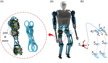
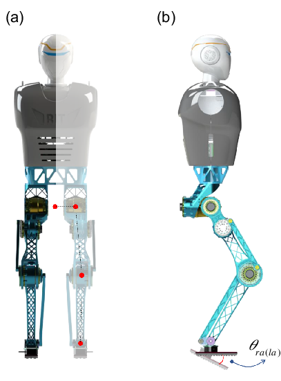
Mechanical structure and degree of freedom configuration of the BHR-B2 robot. (a) 3D structure view of the robot. (b) The blue cylinder represents the driving joint of rotation, and the red arrow represents the positive direction of rotation of the joint with the right-handed system. (c) Integrated thigh structure and drive motor layout of the leg.

3.2. Whole-body dynamics control
To realize the trajectory tracking of gait templates on biped robots, the WBC method is adopted as a part of the template. Next, taking robot BHR-B2 as an example, this process is described in detail.
The BHR-B2 robot is a bipedal humanoid robot developed by the Institute of Intelligent Robots of Beijing Institute of Technology, as shown in Fig. 3(a). This robot is designed to be able to move dynamically in complex environments, but it is different from other biped robots with lightweight legs [Reference Zhu, Wang, Yu, Chen and Han33]. The weight distribution of this robot mirrors the proportion of each limb of the human body. BHR-B2 has two legs with four joints, two arms with three joints, and 14 driving DoFs. The total weight of the robot is 40.3 kg. The robot has no roll angle of the ankle to drive the joint, so it is underactuated after contacting the ground. According to the mass ratio of the human thigh and lower leg, we attempted to increase the height of the leg mass. Therefore, an integrated design is adopted in the thigh structure. As shown in Fig. 3(c), a lightweight thigh structure satisfying the strength requirements is designed through topology optimization. Each joint consists of a DC brush-less motor, planetary reducer, and encoder assembled in the rear of the motor. The planetary reducer has a small gear ratio of 17.43 to make direct torque control more accurate and reduce friction influence.
3.2.1. Dynamic model of robot
To verify the algorithm in this study, as shown in Fig. 3(b), we simplify the robot upper body into a rigid body with a local coordinate system
 $\sum _b$
. There are six virtual DoFs between
 $\sum _b$
and the inertial coordinate system
 $\sum _0$
, which are three displacements
 $ [{\begin{array}{*{20}{c}}{{\varepsilon _x}}&{{\varepsilon _y}}&{{\varepsilon _z}}\end{array}} ]^T$
and three rotations
 $ [{\begin{array}{*{20}{c}}{{\theta _x}}&{{\theta _y}}&{{\theta _z}}\end{array}} ]^T$
. The subscripts
 $r$
and
 $l$
represent the right leg and left leg, respectively, and
 $h$
,
 $f$
,
 $t$
, and
 $a$
represent the joints of the hip, femur, tibia and ankle, respectively. The generalized coordinate of a biped robot floating base dynamic model
 $q ={ [{\begin{array}{*{20}{c}}{q_b^T}&{q_r^T}&{q_l^T}\end{array}} ]}$
is set
 \begin{align} {q_b} & ={\left[{\begin{array}{*{20}{c}}{{\varepsilon _x}}&\quad {{\varepsilon _y}}&\quad {{\varepsilon _z}}&\quad {\begin{array}{*{20}{c}}{{\theta _x}}&\quad {{\theta _y}}&\quad {{\theta _z}} \end{array}} \end{array}} \right ]^T}\nonumber\\[4pt]{q_r} & ={\left[{\begin{array}{*{20}{c}}{{\theta _{rh}}}&\quad {{\theta _{rf}}}&\quad {{\theta _{rt}}}&\quad {{\theta _{ra}}} \end{array}} \right ]^T}\\[4pt]{q_l} & ={\left[{\begin{array}{*{20}{c}}{{\theta _{lh}}}&\quad {{\theta _{lf}}}&\quad {{\theta _{lt}}}&\quad {{\theta _{la}}} \end{array}} \right ]^T}\nonumber \end{align}
Through the Lagrange equation, we can obtain the dynamic equation as follows:
 \begin{align} M(q)\ddot q + N(q,\dot q) = B\tau + J_r^T{\lambda _r} + J_l^T{\lambda _l} \end{align}
where
 $M(q) \in \mathbb{R}^{14 \times 14}$
is the inertia matrix and
 $N(q,\dot q) \in \mathbb{R}^{14 \times 1}$
is the Coriolis force and gravity vector.
 $B \in \mathbb{R}^{14 \times 8}$
is the driving torque mapping matrix and
 $\tau \in \mathbb{R}^{8 \times 1}$
is the driving torque of the leg joints.
 $J_r \in \mathbb{R}^{6 \times 14}$
and
 $J_l \in \mathbb{R}^{6 \times 14}$
are the Jacobian matrix of the relative inertial system of the right and the left ankle, respectively, and
 $\lambda _r \in \mathbb{R}^{6 \times 1}$
and
 $\lambda _l \in \mathbb{R}^{6 \times 1}$
are external forces and moments on the ankle.
 $\dot q$
and
 $\ddot q$
are the first-order differential and the second-order differential of
 $q$
, respectively.
3.2.2. Quadratic optimization formulation
The acceleration
 $\ddot q$
, driving torque
 $\tau$
, and external force of both feet are selected as optimization variables; the cost function is mainly composed of the following four parts. The acceleration at the end of the support leg is zero
 \begin{equation}{\Gamma _1} = \left \|{\dot J_s^v\dot q + J_s^v\ddot q} \right \|_{{w_1}}^2 \end{equation}
where
 $ \| \cdot \|^2$
is a vector two norm operator,
 $w_1$
is a weight matrix with all positive numbers, and the superscript
 $v$
of the Jacobian matrix represents the linear velocity component of three rows. The following cost functions are also expressed in this way. Following the desired acceleration value
 $\ddot p_{sw}^d$
at the end of the swing leg requires
 \begin{equation}{\Gamma _2} = \left \|{\dot J_{sw}^v\dot q + J_{sw}^v\ddot q - \ddot p_{sw}^d} \right \|_{{w_2}}^2 \end{equation}
 \begin{equation} \ddot p_{sw}^d ={k_p}\left(p_{sw}^d -{p_{sw}}\right) +{k_{\dot p}}\left(\dot p_{sw}^d -{{\dot p}_{sw}}\right) \end{equation}
where
 $k_p$
and
 $k_{\dot p}$
are proportional-derivative (PD) controller parameters.
 $w_2$
is a weight matrix with all positive numbers.
All trajectories are established relative to the upper body coordinate system in the trajectory generation of the gait template, so we want the upper body to remain vertical in control. Spring damping virtual model control is introduced to the roll and pitch DoF of the upper body to produce the desired reference acceleration
 \begin{align} \ddot \theta _x^d & = -{k_{\text{roll}}^1}{\theta _x} -{k_{\text{roll}}^2}{{\dot \theta }_x}\nonumber\\[4pt] \ddot \theta _y^d & = -{k_{\text{pitch}}^1}{\theta _y} -{k_{\text{pitch}}^2}{{\dot \theta }_y} \end{align}
where
 $k^1$
and
 $k^2$
are the stiffness and damping coefficients, respectively. Since BHR-B2 has no relevant DoFs for yaw angle control, we ignore the
 $\ddot \theta _z^d$
. All leg joints can use a PD controller to generate reference acceleration through the reference trajectory and actual state, but for the supporting leg, we do not track the trajectory of the hip and ankle, so the optimization problem is more sparse. The tracking objective function of joint acceleration is
 \begin{equation}{\Gamma _3} = \left \|{{B_{\ddot q}}\ddot q -{{\ddot q}^d}} \right \|_{{w_3}}^2 \end{equation}
where
 $B_{\ddot q}$
is the acceleration selection matrix of the controlled DoFs.
 $w_3$
is a weight matrix with all positive numbers. The reference acceleration is
 \begin{equation}{{\ddot q}^d} ={\left[{\begin{array}{*{20}{c}}{\ddot \theta _x^d}&\quad {\ddot \theta _y^d}&\quad {{\ddot \theta _{st}}}&\quad {{\ddot \theta _{swh}}}&\quad {{\ddot \theta _{swf}}}&\quad {{\ddot \theta _{swt}}}&\quad {{\ddot \theta _{swa}}} \end{array}} \right ]^T} \end{equation}
In addition, to avoid high-frequency oscillation and sudden changes in joint torque, the objective function of joint torque is also needed
 \begin{equation}{\Gamma _4} = \left \|{\tau -{\tau ^{\text{last}}}} \right \|_{{w_4}}^2 \end{equation}
where
 $\tau ^{\text{last}}$
is the last driving torque of the leg joints. The objective function of the final quadratic optimization (QP) is
 \begin{equation} \begin{array}{*{20}{c}}{\mathop{\min }\limits _{\ddot q,\tau,{\lambda _r},{\lambda _l}} }&{{\Gamma _1} +{\Gamma _2} +{\Gamma _3} +{\Gamma _4}} \end{array} \end{equation}
In addition to the constraint of the system dynamic equation of Eq. (17), joint driving capacity, and the friction cone of contact force of the supporting leg, the ZMP of the sole-plate should be within the support range (within the sole of the support foot)
 \begin{align} {{\tilde \lambda }_s} & = \left[{\begin{array}{*{20}{c}}{R_s^{\text{foot}}}&\quad {{{\bf{0}}^{3 \times 3}}}\\[6pt]{{{\bf{0}}^{3 \times 3}}}&\quad {R_s^{\text{foot}}} \end{array}} \right ]{\lambda _s}\nonumber\\[8pt] & \quad -{L_{\text{heel}}} \le \dfrac{{ - \tilde \lambda _s^{{\tau _y}} - \tilde \lambda _s^{{f_x}}d_{\text{an}}}}{{\tilde \lambda _s^{{f_z}}}} \le{L_{\text{toe}}} \end{align}
where
 $R_s^{\text{foot}}$
is the rotation matrix of the supporting foot relative to the inertial system, and
 ${\tilde \lambda }_s$
is the external force in the local coordinate system of the sole of the supporting foot.
 $d_{\text{an}}$
,
 $L_{\text{heel}}$
, and
 $L_{\text{toe}}$
are the ankle height, horizontal distance from the rear heel to the ankle, and horizontal distance from the front toe to the ankle, respectively. The superscripts of
 ${\tilde \lambda }_s$
are the components of
 ${\tau _y}$
,
 ${f_x}$
, and
 ${f_z}$
, respectively. Since BHR-B2 has no roll joint of the ankle, only ZMP in the
 $x$
direction is constrained here.
3.3. Joint level torque control
BHR-B2 uses the joint torque control mode to execute the gait trajectory. In addition to the output torque
 $\tau$
controlled by the whole-body dynamics, each leg joint needs to be closed loop for the position and speed of the joint end. Therefore, the final form of control torque is
 \begin{align} \tau _{ij}^c & ={\tau _{ij}} + k_{ij}^p\left(\theta _{ij}^d -{\theta _{ij}}\right) + k_{ij}^d\left(\dot \theta _{ij}^d -{{\dot \theta }_{ij}}\right)\nonumber\\[4pt] i & \in \{ r,l\},j \in \{ h,f,t,a\} \end{align}
where
 $k^p$
and
 $k^d$
are the PD controller gain coefficients.
4. Simulation and experimental results
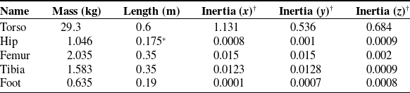
The method presented in this paper is verified by simulation in the ComppeliaSimFootnote 1 simulation environment with Bullet 2.83 and by experiment with the BHR-B2 robot. We use the eigen-quadprogFootnote 2 QP solver to optimize the solution. The BHR-B2 model parameters used are shown in Table I. The initial gait template parameters in the simulation are
 $T=0.4~\rm{s}$
,
 $\alpha = 0.5$
,
 $v_x^{d}= 0~\rm{m/s}$
,
 $v_y^{d}=0~\rm{m/s}$
,
 $H_s^{d}=0.7~\rm{m}$
,
 $h_{sw}^d = 0.1~\rm{m}$
, and
 $W_s^d = 0.0375~\rm{m}$
. Some parameters in the control are as follows:
 $d_{\text{an}}= 0.0645~\rm{m}$
,
 $L_{\text{toe}} = 0.12~\rm{m}$
, and
 $L_{\text{heel}} = 0.07~\rm{m}$
. The gain parameters in this method, PD controller, and weight coefficient in optimization can be set manually and by conventional experiments, which are not shown here.
Dynamic parameters of robot.

† The moment of inertia about the coordinate axis in kg
 $\cdot$
m
 $^2$
.
* The width of the hip.
4.1. Inverse kinematics of BHR-B2
The robot increases the initial position between the two feet through the paranoia of the
 $y$
-direction of the legs to increase the robot’s adjustment range to deal with the changes in the complex environment (Fig. 4). In addition, the reference track will change suddenly when the leg state of the state template changes. Therefore, the inverse kinematic algorithm based on the QP solution is used to obtain a smooth trajectory similar to [Reference Fengy, Whitmanz, Xinjilefuy and Atkeson34].
The leg geometry of the robot. The inverse kinematics solution is only for the four driving DoFs of the legs.

According to the setting of the gait template, we need to solve the pose of each leg end (the foot) relative to the upper body. We set the endpoint as the front edge of the sole to include the ankle joint, which is conducive to constraining the pose of the sole relative to the ground. We choose the increment of the joint angle
 $\Delta{q_{r,l}} \in{\mathbb{R}^{4}}$
as the optimization variables to meet the joint angle limit more conveniently; the lower corner mark indicates the right or left leg. Finally, the solution results are obtained according to the current leg state
 ${q_{r,l}} \in{\mathbb{R}^{4}}$
. The optimization objective consists of three parts. The first part is the control of the end position and speed
 \begin{align} {\Psi _1} & = \left \|{{{\hat J}_{r,l}}\Delta{q_{r,l}} - \hat v_{r,l}^d\Delta T} \right \|_{{Q_1}}^2\nonumber\\[4pt] \hat v_{r,l}^d & = v_{r,l}^d +{k_{IK}}\left(p_{r,l}^d -{p_{r,l}}\right) \end{align}
where
 ${\hat J}_{r,l}$
represents the Jacobian matrix of the leg,
 $\hat v_{r,l}^d$
represents the target speed at the end of the foot, which is obtained by superimposing the position error on the reference speed
 $v_{r,l}^d$
,
 $p_{r,l}$
represents the current position, and
 $p_{r,l}^d$
represents the reference position.
 $k_{IK}$
is a constant gain parameter, which we set to
 $10$
. The control period
 $\Delta T$
is
 $1~\text{ms}$
in the simulation and experiment.
 $Q_1$
is a weight matrix with all positive numbers.
The second part is to keep the increment as small as possible. In addition, to avoid the oscillation of the solution, the constraint with the last result
 $\Delta q_{r,l}^{\text{last}}$
should be added
 \begin{align} {\Psi _2} = \left \|{\Delta{q_{r,l}}} \right \|_{{Q_2}}^2 + \left \|{\Delta{q_{r,l}} - \Delta q_{r,l}^{\text{last}}} \right \|_{{Q_3}}^2 \end{align}
 $Q_2$
and
 $Q_3$
are weight matrices with all positive numbers.
The third part is the optimal solution for the foot posture. Because the joint configuration of the robot’s legs cannot control the position and posture of the foot at the same time, only the control of the foot pitch angle remains
 \begin{align} {\Psi _3} = \left \|{\varsigma (\Delta{q_{r,l}}) -{\theta _{(r,l)a}}} \right \|_{{Q_4}}^2 \end{align}
where
 $\varsigma (\Delta{q_{r,l}})$
represents the forward kinematics of the pitch angle of the foot relative to the upper body calculated from the joint angle and
 $\theta _{(r,l)a}$
represents the desired pitch angle of the footplate. Because the torque control of the robot’s ankle joint will make it conform to the ground and produce different angles, when it becomes a swinging leg,
 $\theta _{(r,l)a}$
needs to interpolate from the current angle to the desired angle. This process can solve the sudden change of inverse kinematics when changing the leg state. The objective function of the final QP optimization is
 \begin{align} {\mathop{\min }\limits _{\Delta{q_{r,l}}} } {{\Psi _1} +{\Psi _2} +{\Psi _3}} \end{align}
The constraints of the optimization problem include joint velocity and angle constraints:
 \begin{align} {\phi _{\min }} & \le{q_{r,l}} + \Delta{q_{r,l}} \le{\phi _{\max }}\nonumber\\[5pt]{{\dot \phi }_{\min }} & \le \dfrac{{\Delta{q_{r,l}}}}{{\Delta T}} \le{{\dot \phi }_{\max }} \end{align}
where
 ${\phi _{\max }},{\phi _{\min }},{{\dot \phi }_{\max }}$
, and
 ${\dot \phi }_{\min }$
represent the maximum and minimum angle and speed limits. For example, the knee joint angle of the leg cannot be positive to avoid anti-joint effects. The final solution of inverse kinematics is
 $q_{r,l}^d ={q_{r,l}} + \Delta{q_{r,l}}$
.
4.2. Dynamically adjusted template parameters in simulation
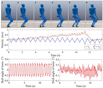
First, the dynamic variable speed is tested in the simulation. By randomly changing the reference speed
 $v_x^d$
of the gait template with
 $v_y^d = 0$
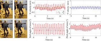
, the effectiveness of real-time planning of the template and robustness of the control algorithm are verified, as shown in Fig. 5. We gradually increase the reference speed to a maximum of 0.7 m/s in steps of 0.1 m/s. With the increase in
 $v_x^d$
, the step length of the robot changes significantly through the screenshots, which shows the real-time effectiveness of the gait template. The actual speed
 $v_x$
stably tracks the desired speed with small error. The lateral velocity fluctuates periodically around zero, because the ankle lacks the DoF in this direction. The speed tracking effect indicates that the speed control in the controller is adequate. The posture angle of the upper body changes in a small range during variable speed walking, showing the control algorithm’s effectiveness. The upper body should be kept upright to increase the stability of walking.
Walking simulation under different reference speeds. Above: screenshots of the simulation experiment. Central: running speed curve of the robot. Below: roll and pitch angle of the robot’s torso posture.

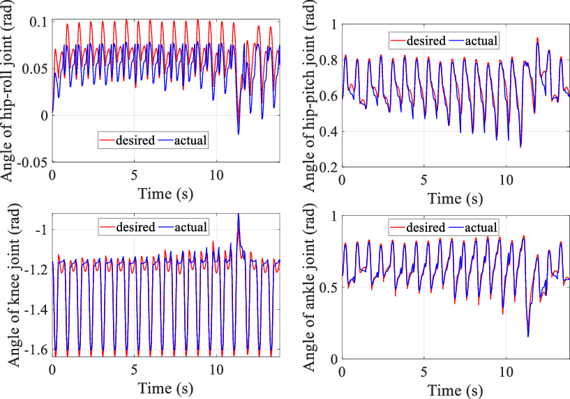
Figure 6 shows the tracking of the driving joint of the right leg during walking, and the gait shows periodicity. The trajectory keeps the robot in dynamic balance, which further illustrates the real-time effectiveness of the gait template.
The tracking curve of four joint angles for right leg in the simulation experiment of dynamic speed change. The red curve represents the desired state and the blue curve represents the actual state.

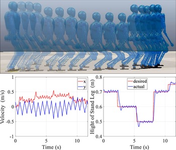
Simulation experiment of a gait template with variable support height. Screenshot of robot simulation and tracking curve of speed and support height. When the robot moves from left to right, the reference height decreases and then increases.

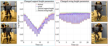
The simulation experiment of dynamic height change is shown in Fig. 7. Stepped reference height changes are smoothed by gait templates, enabling the robot to maintain balance. The stable convergence after the speed mutation indicates the effectiveness of the adjustment in the gait template. Thus, dynamic and accurate height control is realized through a gait template and control algorithm.
4.3. Steady motion experiment
The verification algorithm on a real robot is different from the simulation system because it is difficult to obtain the real value of the robot state and there is considerable noise in the sensor. Friction and other factors produce more inaccuracies in direct drive joint torque control (no torque feedback at the joint end). In the experiment, the state estimation is completed by the Kalman filter (KF) method. The velocity of the joint is obtained by numerical differentiation of the position and filtered by a first-order KF. The robot determines whether it touches the ground by force sensors installed on the soles of its feet. The communication mode of EtherCAT enables the whole control to be completed at a frequency of 1 kHz.
The stable motion control has been tested on the physical robot BHR-B2, as shown in Fig. 8. The controller makes the robot move at a predetermined speed, and the angle error of the upper body is controlled within
 $1 ^\circ$
. The shaking of the upper body will cause some interference to the speed control, but the controller can stabilize the robot within this range.
BHR-B2 stable motion experiment. The protective rope is loose and does not give any support to the robot. The carbon fiber tubes on both sides of the robot’s shoulders are added for protection.

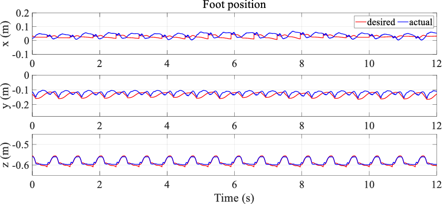
Figure 9 shows the spatial position track of the foot end relative to the upper body generated by the gait template and the actual tracking. Due to the influence of joint friction, the trajectory tracking is not ideal when the motion range of the end of the leg is small in the
 $x$
and
 $y$
directions. Especially in the leg support stage, considerable position tracking accuracy is lost to maintain the upper body posture. However, the position control in the
 $z$
-direction shows good tracking performance without the influence of other control targets. When the leg changes from the support phase to the swing phase, the reference position will change suddenly to the current actual position to avoid the sudden change in control torque, which is also the trajectory switching effect caused by the event trigger in the gait template. Using the method in subsection 2.2, the gait template can effectively transition this process.
Gait template desired trajectory and actual tracking effect during steady motion. The curve represents the position of the leg end relative to the upper body, so the
 $z$
-direction is negative. When the value in the
 $z$
-direction is smooth, it is the support stage of the current leg.

4.4. Dynamic variable template parameter in the experiment
We also experimented with dynamically adjusting the template parameters when the robot changes the height of the supporting leg, the height of the lifting foot, and the walking cycle. Figure 10 shows the experimental results of the first two parameters. The support height changes in steps from 0.48 to 0.62 m, and the curve represents the periodic position change of the upper body relative to the end of the right leg. The maximum value represents the expected support height, and the relative value in the process of reciprocating changes represents the height of leg lifting. The foot lifting height changes from 0.05 to 0.1 m. The curve represents the periodic position change of the upper body relative to the end of the right leg. The maximum value represents the expected support height, and the relative value in the process of reciprocating changes represents the height of leg lifting. Therefore, the experiment verifies the dynamic correctable characteristics of the gait template, and the control algorithm enables the robot to maintain balance.
Dynamic adjustment of support height and swing foot lifting height. The left side is the variable height experiment, and the right side is the variable foot lifting height experiment. The numerical interval between the green circle and the black circle indicates the height of foot lifting. The blue line in the video screenshot is marked with a reference datum to make this change more obvious.

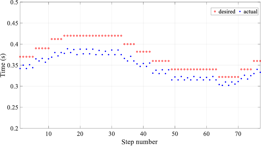
Figure 11 shows the change in the walking cycle. The slight difference between the reference walking cycle and the actual walking cycle is because the swinging leg touches the ground in advance, which makes the leg state change. The real-time planning of the gait template causes smooth switching between two gait frequencies, and the robot can move steadily. There are differences between the two adjacent blue dots in the figure, which indicates that the performance of the left and right legs on the robot is not the same, which again indicates the challenge of experimental verification.
Variable walking cycle time experiment. The horizontal axis represents the number of steps. The red circle indicates the expected walking cycle time, and the blue dot indicates the actual running time.

5. Conclusions
This study uses the UBR without roll DoF in the ankle to verify the algorithm. The simulation and experimental results show the feasibility of the gait template and the algorithm’s robustness. In real time, we can generate a walking gait with variable speed, step size, and metamorphic center height through the proposed model-free walking template. This advantage makes the real-time adjustment more reliable and faster. The template parameters which can be changed in real time will grant the robot improved robustness in the dynamic environment. For example, the robot can squat through low spaces, change the lifting height in rugged terrain, and accelerate the gait frequency (reduce the walking cycle) after being significantly disturbed to achieve rapid stability. Flexible motion generation and stable control methods will contribute to the further development of human−robot cooperation and interaction, such as remote synchronization of human and robot actions [Reference Su, Qi, Schmirander, Ovur, Cai and Xiong35]. In this study, we have tested the feasibility of a gait template with dynamically adjusted parameters and the effectiveness of the control algorithm. Further verification in complex environment application scenarios has not been carried out, which will be the focus and direction of our future work. It should be noted that there are still some limitations in verifying this algorithm in complex environments, such as the real-time and accuracy requirements of environmental awareness and parameter decision algorithms in different scenarios.
In future work, we will use multi-parameter optimization for the end planning of the swing leg to adapt to more complex environments and mission scenarios, such as climbing stairs. We believe that the artificial intelligence algorithm may help in dealing with the multi-parameter adjustment in complex situations [Reference Su, Hu, Karimi, Knoll, Ferrigno and De Momi30]; we will also try to use neural networks to adjust gait template parameters cooperatively.
Acknowledgments
This work was supported by the National Key Research and Development Program under Grant (2018YFE0126200) and the National Nature Science Foundation of China under Grant (62103053). We thank Wei-wei Wang and Min Zhu for their contributions to the construction of the robot system.
Author’s contributions
Lianqiang Han put forward the theory and carried out experimental verification; Xuechao Chen and Zhangguo Yu improved and revised the idea and manuscript; Zhifa Gao and Jintao Zhang designed the experimental process; Gao Huang designed the platform; Kenji Hashimoto and Qiang Huang supervised and managed the project. All authors have read and agreed to the published version of the manuscript.
Competing interests declaration
The authors declare none.
Ethical considerations
None.