

INTRODUCTION
Most research dealing with salt plugs focuses on the details of diapir penetration mechanisms, fracture pattern through the overburden strata, and basin stratigraphic architecture to study potential hydrocarbon reservoirs (Schultz-Ela et al., Reference Schultz-Ela, Jackson and Vendeville1993; Smith et al., Reference Smith, Hodgson and Fulton1993; Stewart and Clark, Reference Stewart and Clarke1999; Davison et al., Reference Davison, Alsop, Birch, Elders, Evans, Nicholson, Rorison, Wade, Woodward and Young2000; Hudec and Jackson, Reference Hudec and Jackson2007; Hudec et al., Reference Hudec, Jackson and Schultz-Ela2009; Trudgill, Reference Trudgill2011). According to Stewart (Reference Stewart2006), there are three different structural domains with characteristic fault styles around a salt diapir: (1) the roof zone, (2) the diapir flanks or drag zone, and (3) the root zone. Field evidence, seismic interpretations, and physical modeling indicate that the deformation related with active diapirism is mainly characterized by doming, radial faulting and occasionally conic grabens in the roof area (Davison et al., 1993, Reference Davison, Alsop, Birch, Elders, Evans, Nicholson, Rorison, Wade, Woodward and Young2000; Schultz-Ela et al., Reference Schultz-Ela, Jackson and Vendeville1993; Rowan et al., Reference Rowan, Lawton, Giles and Ratliff2003; Dooley et al., Reference Dooley, Jackson and Hudec2009), drag folding and inward- or outward-dipping concentric faults depending on the geometry of the diapir crest in the sheared sediments around the diapir flanks (Davison et al., Reference Davison, Insley, Harper, Weston, Blundell, Mcclay and Quallington1993; Alsop, Reference Alsop1996; Stewart, Reference Stewart, Harvey, Otto and Weston1996; Yamada et al., Reference Yamada, Okamura, Tamura and Tsuneyama2005), and primary and secondary rim synclines in the periphery caused by salt redistribution at depth during diapir initiation and growth, respectively (Trusheim, Reference Trusheim1960; Stewart, 1996; Sørensen, Reference Sørensen1998; Doelling et al., Reference Doelling, Ross and Mulvey2002). Parker and McDowell (Reference Parker and McDowell1955), Withjack and Scheiner (Reference Withjack and Scheiner1982), and Yamada et al. (Reference Yamada, Okamura, Tamura and Tsuneyama2005) analog models show that this overview of the structural deformation pattern may vary depending on the size and shape of the salt dome, the overburden thickness, the amount of uplift, and the regional tectonic stress field.
There has been relatively little previous work on the collapse of salt diapirs, and most of the information on this topic comes from physical modeling (Vendeville and Jackson, 1992a, Reference Vendeville and Jackson1992b; Jackson and Vendeville, Reference Jackson and Vendeville1994; Ge and Jackson, Reference Ge and Jackson1998; Gaullier and Vendeville, Reference Gaullier and Vendeville2005; Jackson et al., Reference Jackson, Adams, Dooley, Gillespie and Montgomery2011). Deformational configuration of the diapir roof predicted by analog models is in clear disagreement with fieldwork studies (Gutiérrez, Reference Gutiérrez2004; Guerrero et al., Reference Guerrero, Brunh, McCalpin, Gutiérrez and Willis2015). Furthermore, there are no detailed geologic studies on the interaction between dissolution collapse and growing diapirs, and the fracture pattern of the overburden when salt dissolution counterbalances or exceeds the upwelling rate. Good exposures and accessibility of the Spanish Salinas de Oro salt diapir in the western Pyrenees provide an example and analog to study: (1) the dissolutional collapse structures of the diapir crest to compare with analog models and previous field studies, (2) the relationship between radial faulting and concentric-ring faulting, and (3) the influence of cover rheology on diapir shape. Using Quaternary mapping and field studies of the Salinas de Oro diapir, this study therefore provides the first example of how concentric-ring faulting relates to the interstratal dissolution of a growing diapir. The displacement of fluvial terrace, pediment, and slope deposits by radial, salt-withdrawal, and concentric faults is used to demonstrate salt diapir rising, salt migration, and karstification throughout the Quaternary and allows comparisons to be made between their current and long-term slip rates.
GEOLOGIC SETTING
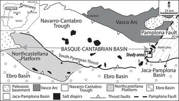
The Salinas de Oro salt diapir located in the Basque-Cantabrian Basin in the western Pyrenees orogen in Spain is a classic oval-shaped Lower Cretaceous diapir (Fig. 1). The diapir covers an area of 184 km2 and has vertical walls made up of Triassic evaporates. The Pyrenees are a narrow alpine mountain range elongated east-southeast to west-northwest along the boundary between the Iberian microplate to the south and the Eurasian plate to the north. The Basque-Cantabrian Basin is divided into three geologic provinces separated by thrust faults; from east to west, these include the Vasco Arc, the Navarro-Cántabro Trough, and the Norcastellana Platform, with the last two provinces dominated by salt tectonics (Barnolas and Pujalte, Reference Barnolas and Pujalte2004). The 120-km-long Pamplona Fault is a nonoutcropping northeast–southwest trending extensional transverse basement fault that controlled the sedimentation during the Mesozoic (Fig. 1). The Pamplona Fault delineates the boundary between the Basque-Cantabrian Basin in the western Pyrenees and the Jaca-Pamplona Basin in the central Pyrenees (Turner, Reference Turner1996; Olive et al., Reference Olive, López-Horgue, Baceta, Niñero and Villanueva2010). The south Pyrenean thrust constitutes the boundary of the Navarro-Cántabro Trough and the Jaca-Pamplona Basin with the Ebro Foreland Basin (Fig. 1).
Simplified geologic sketch of the Basque-Cantabrian Basin and location of the study area. Numbers 1 to 5 represent Triassic salt diapirs aligned along the Pamplona basement fault (1, Allo; 2, Arteta; 3, Salinas de Oro; 4, Alloz; 5, Estella).

The Salinas de Oro salt diapir is located in the Navarro-Cántabro Trough province and belongs to a group of five well-developed piercing Lower Cretaceous diapirs aligned along the Pamplona Fault. From north to south, these include the Ollo, Arteta, Salinas de Oro, Alloz, and Estella diapirs (Fig. 1). These salt diapirs are made up of Keuper and Muschelkalk halite interlayered with anhydrite, gypsum, shale, limestone and dolomite, and intruded mafic volcanic rocks (Olive et al., Reference Olive, López-Horgue, Baceta, Niñero and Villanueva2010). The original thickness of halite in the Navarro-Cántabro Trough is difficult to estimate, although it may represent more than 80% of the total Triassic strata thickness. Seismic reflection and borehole data conclude that Triassic facies vary significantly in thickness from tens of meters in the basin margins to >8000 m in salt diapirs because of salt migration (Serrano and Martinez del Olmo, Reference Serrano and Martinez del Olmo1990, 2004). An average estimated thickness of Keuper and Muschelkalk beds together lies between 2500 and 3000 m with interlayered halite bodies being more than 300 m thick (Instituto Geológico y Minero de España [IGME], 1990a, 1990b).
Salvany (Reference Salvany1990), Serrano and Martinez del Olmo (Reference Serrano and Martinez del Olmo1990, 2004), and García-Mondéjar (Reference García-Mondéjar1996) argue that halokinetic processes started during the opening of the North Atlantic in the Lower Cretaceous under an extensional tectonic regime probably because of the reactivation of the Pamplona Fault. Reactive diapirism gave way to subbasins and salt highs that largely controlled the sedimentation of thick Mesozoic limestones in rim depocenters (Pflug, Reference Pflug1973; Pinto et al., Reference Pinto, Casas, Rivero and Torné2005). Salt movement acceleration at the end of the Cretaceous coincided with a change in the tectonic regime from extensional to compressional because of the oblique convergence and subduction of the Iberian plate beneath the European plate (Ramírez et al., Reference Ramírez, Olive, Alvaro, Ramírez del Pozo, Meléndez, Gutiérrez Elorza, Carbayo, Villalobos, León and Gabaldón1987; Muñoz, Reference Muñoz1992). According to Salvany (Reference Salvany1990), the Salinas de Oro salt diapir was squeezed and pierced the surface by the end of the Cretaceous. After these initial stages of tectonic shortening and salt uplift, a period of thermal subsidence occurred, and the area underwent a succession of transgressions and regressions from the Maastrichtiense to the end of the Eocene. This led to an up to a 1400-m-thick sequence of calcarenites and bioclastic limestones that covered the salt diapirs (Castiella et al., Reference Castiella, Sole, Segismundo and Otamendi1982; Ramírez et al., Reference Ramírez, Olive, Alvaro, Ramírez del Pozo, Meléndez, Gutiérrez Elorza, Carbayo, Villalobos, León and Gabaldón1987; Salvany, Reference Salvany1990). The strata deposited during this period are divided into four megasequences that are, from base to top, as follows (Olive et al., Reference Olive, López-Horgue, Baceta, Niñero and Villanueva2010): (1) 50 to 80 m of Upper Cretaceous marls and limestones underlying a 150- to 250-m-thick Paleocene sequence consisting of a basal 50-m-thick dolomitic unit, intermediate 100-m-thick bioclastic limestones, and upper 40- to 50-m-thick marls, (2) 130 m of Lower Eocene calcarenites and limestones with abundant reworked benthonic foraminifera, (3) 350 m of Middle Eocene cross-bedded limestones and bioclastic calcarenites with two interbedded marl beds with thickness of 10–15 m and up to 40 m thick, 40 m and 80–90 m from the base, respectively, that were used as stratigraphic markers to estimate fault throw (Middle Eocene rocks unconformably overlie the Lower Eocene and Cretaceous sequence), and (4) up to 600-m-thick Middle and Upper Eocene gray marls with an assemblage of planktonic foraminifera that typifies the Morozovella lehneri and Truncorotaloides rohri biozones (40 to 37 Ma) (Payros et al., Reference Payros, Pujalte, Baceta, Orue-Etxebarria and Serrakiel1996; Payros, Reference Payros1997).
A reactivation of the previous salt structures occurred at the beginning of the Oligocene in relation with an important orogenic stage that caused the uplift of the Basque-Cantabrian Basin, piggyback thrusting, the development of the Ebro Foreland Basin, and the accumulation of several thousands of meters of endorheic continental sediments related to thrust loading (Vergés et al., Reference Vergés, Fernàndez and Martínez2002). During this period, halokinesis is recorded by syntectonic unconformities in Oligocene and Miocene continental sediments as alluvial fans and lakes migrated to the southwest away from the salt stocks (Serrano and Martinez del Olmo, Reference Serrano and Martinez del Olmo1990; Olive et al., Reference Olive, López-Horgue, Baceta, Niñero and Villanueva2010; Quintà et al., Reference Quintà, Tavani and Roca2012). The end of this period of rapid deformation coincided with the initiation of an extensional regime and the transfer of tectonic deformation from the Pyrenees to Betic Mountains in southernmost Spain, together with the opening of the Valencia Trough in the Mediterranean Sea during the Miocene (Vergés et al., Reference Vergés, Fernàndez and Martínez2002). The Ebro Foreland Basin was captured and opened toward the Mediterranean Sea in the Middle–Upper Miocene, (García-Castellanos et al., 2003; Pérez-Rivares et al., 2004), and a new drainage network started to dissect the endorheic basin fill. Since then, the salt diapirs have undergone intense erosion and karstic dissolution that resulted in cylindrical depressions surrounded by vertical limestone cliffs.
METHODOLOGY
This investigation began with the production of a preliminary map of the study area based on the interpretation of color stereoscopic aerial photographs printed at a scale of 1:30,000 and the review of published geologic information. The geologic maps of Salinas de Oro salt diapir produced by Olive et al. (Reference Olive, López-Horgue, Baceta, Niñero and Villanueva2010) were very useful for assessing the bedrock geology. The geologic map was refined in the field using color 1:5000 scale orthophotographs. Special attention was paid to the distribution of fault scarps and faulted Quaternary deposits to determine crosscutting relationships and fault motion. The geologic database was developed on a geographic information system (ArcGIS 10.1) using orthoimages with a pixel size of 50 cm and a digital elevation model with a pixel size of 25 cm from the Spanish National Geographic Institute.
Geologic cross sections were projected based on fieldwork mapping and borehole information provided by the Spanish Geological Survey (IGME, 1990a, 1990b). Special care was taken with the unconformity underlying the Middle Eocene beds that was delineated using detailed fieldwork surveys of the base and top of the deepest units. In this respect, Paleocene dolomites and Middle Eocene marl beds were good markers to determine the thickness of units and throw of faults and to trace the unconformity. Where the deeper levels did not crop out, the thickness of Middle Eocene and Paleocene/Lower Eocene units was extrapolated from the nearest outcrop. In such cases, geologic contacts in the cross sections were delineated using a dashed line (inferred contact), and fault throw became an estimated value (estimated throw).
STRUCTURAL CONFIGURATION OF SALINAS DE ORO SALT DIAPIR
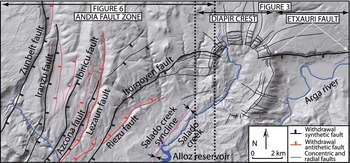
The Salinas de Oro salt diapir can be divided into three main domains with different deformation style: (1) the diapir crest, (2) the Etxauri Fault, and (3) the Andia Fault Zone (AFZ) (Fig. 2).
(color online) Hill-shade model of the study area and location of the Salinas de Oro salt diapir, the Etxauri Fault, and the Andia Fault Zone domains together with the radial, concentric, and salt-withdrawal master faults.

Diapir crest
The Salinas de Oro salt diapir has an area of 11.4 km2 and is a classic oval-shaped diapir of Keuper and Muschelkalk salt with very steep sides and no overhangs (Pinto et al., Reference Pinto, Casas, Rivero and Torné2005). The main axis trends north and has a length of 5.7 km. Seismic reflection, well exploration data, and three-dimensional gravity models indicate that salt walls extend vertically for >7 km down to Paleozoic basement (IGME, 1990a, 1990b). The salt diapir pierces a gentle folded overburden of around 200 m of Jurassic anhydrites and dolomites, 3000 m of Cretaceous limestones and marls, and up to 800 m of Paleocene and Eocene limestones, calcarenites, and marls (IGME, 1990a, 1990b; Olive et al., Reference Olive, López-Horgue, Baceta, Niñero and Villanueva2010). This carbonate sequence has been shouldered aside by >150 m above its surroundings leading to an annular limestone escarpment at the diapir contact. The beds are tilted to dips of 75°, vertical or even overturned at the contact with the Triassic evaporites. This leads to vertical limestone ridges that become dip slopes away from the diapir as the dip decreases. Oligocene and Miocene conglomerates, sandstones, and clays unconformably overlie the Early Tertiary limestones on the southern flank with dips of 50° progressively decreasing to 10–20° outward from the diapir (Fig. 3).
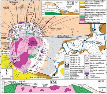
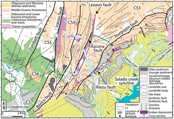
(color online) Geologic and geomorphic map of the Salinas de Oro salt diapir and the Etxauri Fault showing crosscutting relationship between radial grabens and concentric faults. Vertical and horizontal scales are the same in the cross sections. Coordinates: upper left corner X: 42.830357, Y: −1.911573; lower right corner X: 42.830357, Y: −1.778958.

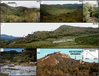
The center of the salt diapir is today a topographic depression some 300 m below the surrounding annular limestone escarpment, which is breached by the Salado Creek through its southwestern wall along a radial graben (Fig. 3). The top of the diapir is covered by a thick caprock mainly composed of massive and distorted red and gray clays that engulf thick bodies of Triassic volcanic mafic rocks. The caprock is affected by more than a hundred bending and collapse sinkholes between 2 and 310 m and up to 70 m deep that sum a total area of 0.78 km2 (7.6% of the salt outcrop) and give way to a density of 9.3 sinkholes/km2 (Fig. 4A).
(color online) (A) Sinkhole more than 70 m in diameter that hosts a permanent lake and developed in a graben formed between conjugate synthetic and antithetic concentric faults. (B) The 24 km2 Ibozak sinkhole acting as a big ponor allowing runoff to enter into the Triassic interstratal karst system. (C) Open fissure related to extension along a subvertical, synthetic, concentric fault. (D) Sequence of concentric inward-dipping faults displacing the Paleocene limestones and dolomites and crosscut by the Urdanoz radial fault. (E) Salterns in the Salinas de Oro diapir. (F) Keystone graben developed in the hinge of the annular concentric monocline and longitudinal profile (in meters) of defeated streams flowing transversely into it.

The bigger depressions often have nested collapse sinkholes that may be >80 m in diameter. Some depressions show irregular shapes and flat bottoms as a result of sinkhole coalescence and intense alluvial sedimentation and filling (Fig. 4B). Most of the sinkholes have developed along the Salado Creek valley and at the western, northern, and eastern edges of the salt diapir in the contact with the Triassic evaporites and the carbonate overburden at the intersection with radial faults, which suggests that dissolution is structurally controlled (Fig. 3). Some sinkholes intercept local piezometric levels developed in the limestone sequence hosting permanent lakes (Fig. 4A). Other sinkholes act as swallow holes that disrupt the local drainage and allow the entrance of runoff into the endokarst and the interstratal dissolution of salt.
Dissolution-induced subsidence in the western, northern, and eastern crest and flanks of the diapir has been accommodated by both passive bending (folding) and brittle collapse (normal faulting) of the overburden. The Paleocene and Eocene strata downsag toward the center of the diapir forming an annular monocline with limb dips between 10 and 45°. This monocline is broken by a sequence of inward-dipping concentric normal faults and graben structures (Figs. 3 and 4D). Using the base of the Paleocene sequence as a marker, the net vertical displacement related to karstic sagging and collapse is around 90 m (Fig. 3, cross section CS1). In paleoseismology, the net vertical displacement of a fault is defined as the total throw across the entire deformation zone, calculated as the difference between synthetic and antithetic throws (McCalpin, Reference McCalpin2009). Synthetic faults that accommodate most of the vertical displacement show throws of >20 m. In contrast, the vertical offset of antithetic faults is mostly between 3 and 10 m, producing uphill-facing scarps. The crest of the monocline is affected by a 9.5 km long and up to 200-m-wide concentric keystone graben with conspicuous geomorphic expression indicating recent formation (Fig. 4F). The vertical offset measured in the central northern and western sectors is around 40 m. Elongated, flat-bottom, 20- to 600-m-long, colluvium-filled closed depressions have developed on the hanging wall. The drainage network has captured most of the depressions while others still remain as endorheic sediment traps (Fig. 3). Linear ground hollows up to 50 m long, 4 m wide, and 1.5 m deep and cover suffosion and collapse sinkholes up to 15 m in diameter are attributed to the downward migration (raveling and piping) of trough-filling deposits through open fissures in the bedrock (Fig. 4C). The development of the keystone graben eventually obstructed several transverse radial flowing streams, creating defeated streams and enclosed depressions on the downthrown block and hanging and beheaded drainage channels in the footwall. The longitudinal profile of these defeated streams has a concave geometry with a gradient change from 10° to an almost flat surface next to the fault scarp (Fig. 4E). This evidence together with the occurrence of fresh-looking scarps, a poorly developed drainage network, open cracks up to 3 m wide and more than 100 m long in the bedrock, and numerous tilted and bent trees growing on fault planes demonstrate the current activity of concentric faults. Collapse related to salt diapir dissolution is especially important at the contact between the Triassic evaporites and Tertiary carbonates at the diapir flanks where elongated sinkholes coalescence to create linear troughs. Here, bedrocks slabs are tilted inward with dips of >30°. These have helped produce landslides (Fig. 3) rooted in the Upper Cretaceous marls leading to an irregular topography made up of a chaotic pile of limestone boulders in the sinkholes.
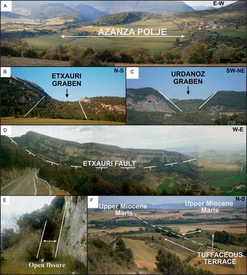
Extension of the overburden during diapir uplift caused the development of radial grabens and fractures that extend from 400 to >3000 m from the limestone escarpment (Fig. 3). The lengths of radial faults between 0.2 and 1 times the radius of this salt diapir are similar to the values obtained in analog models (Alsop, Reference Alsop1996; Yamada et al., Reference Yamada, Okamura, Tamura and Tsuneyama2005; Stewart, Reference Stewart2006; Dooley et al., Reference Dooley, Jackson and Hudec2009). Grabens in the limestone escarpment show vertical throws between 20 to 90 m decreasing to meter-throw faults and finally simple fractures with increasing distance from the diapir center. This fracture pattern has favored the dissolution of the Tertiary limestone sequence and led to the development of a large number of sinkholes aligned along radial faults and poljes. Examples are the Azanza and Arpide poljes with surface areas of 1.14 and 0.77 km2, respectively (Fig. 5A). Movement of the radial faults is disrupting of the drainage network. The western flat-bottom tributary of the Elizaburi Stream has been cut close to the tip of Urdanoz Fault and now hangs 3 m above the present valley bottom that has been captured by the Aranea Stream (Fig. 3). Subsidence along the Azanza graben has breached the limestone escarpment. Similarly, the capture and abandonment of a 300-m-long stream reach that drained several depressions developed at the keystone graben now discharges into Azanza polje instead of Ibokaz sinkhole. The Guembe graben and Urdanoz Fault on the western and northern diapir flanks, respectively, have been reactivated and are offsetting stream and colluvial deposits. This is leading to 2 m fault scarps with meter-size sinkholes and linear troughs along the hanging wall related to the opening of extensional tension cracks in the underlying bedrock. Radial faults overprint the keystone graben and concentric faults that often disappear along the main radial grabens because of their significant offset (Fig. 5B and C).
(A) The 1.14 km2 Azanza polje showing the location of radial faults (white dashed lines). (B and C) Radial grabens of Etxauri and Urdanoz overprinting concentric normal faults, respectively. (D) Panoramic view of the Etxauri Fault scarp and Arga River valley. (E) Open fissure in bedrock related to the motion of secondary reverse faults associated with the Etxauri Fault. (F) Graben in the 45-m-high Quaternary tuffaceous terrace of the Arga River because of the movement of the Etxauri Fault. See the offset of the Upper Eocene marls in the background. (For interpretation of the references to color in this figure legend, the reader is referred to the web version of this article.)

Etxauri Fault
The Etxauri Fault is the most important structure at the eastern flank of the Salinas de Oro salt diapir and gives way to a significant 350-m-high limestone escarpment that brings into contact Cretaceous and Upper Eocene formations (Figs. 3 and 5D). This fault consists of a master normal fault and a swarm of subvertical to overhanging secondary faults that all crosscut dissolutional-induced concentric fractures. These faults have an important lateral displacement component that results in the development of open fissures >200 m long and up to 3 m wide (Fig. 5E) and individualized bedrock pinnacles up to 200 m long and 50 m tall. The Arga River, a tributary of the Ebro River, abruptly changes its direction from south to west at the village of Ibero to flow parallel to the downthrown block of the Etxauri Fault suggesting that its motion may favor the migration of the river toward the hanging wall (Fig. 3). A stepped sequence of three levels of tuffaceous terraces located above the level of the present springs at Etxauri and Ibero in the hanging wall at 70, 45, and 25 m above the present Arga River channel are disturbed by the Etxauri Fault (Fig. 3). The 70-m-high tuffaceous terrace surface is tilted 10° to the south and has been offset 13 m leading to a 130-m-wide graben (Fig. 5F). The net vertical displacement related to tilting and throw is 23 m. Based on altitudinal and spatial terrace correlation, these tuffaceous terraces were considered correlative with terraces T2, T4, and T5 of the Arga River and terraces T6, T8, and T9 of the Ebro River, respectively (Lenaroz, Reference Lenaroz1993). Considering this correlation, the probable age for the 70-m-high Arga River terrace ranges between 178±21 and 151±11 ka from luminescence dating of the Ebro River (Luzón et al., Reference Luzón, Pérez, Soriano and Pocoví2008; Simón et al., Reference Simón, Soriano, Arlegui, Gracia, Liesa and Pocoví2008) and its tributaries deposits (Lewis et al., Reference Lewis, McDonald, Sancho, Peña and Rhodes2009). Using this optically stimulated luminescence age and the net vertical displacement of the terrace, the slip rate of Etxauri Fault ranges from 0.12 to 0.16 mm/yr.
Andia Fault Zone
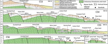
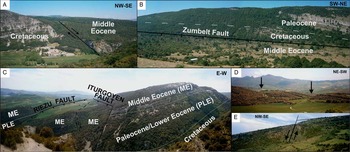
The Andia range consists of by low-dipping dip slopes and structural platforms of Cretaceous, Paleocene, and Eocene limestones and marls. West of Salinas de Oro diapir, the Andia Range is bent to the east by north–south and northeast–southwest trending gentle folds. Synthetic and antithetic normal faults developed in the hinge and limbs of the folds form a wedge-shaped graben system. This graben has an area of ~103 km2 and opens to the northeast and extends 12 km westward and 17 km southwestward from the Salinas de Oro salt diapir (Fig. 6). The faults trend north to northeast with important vertical throws of up to several hundred meters. The estimated net vertical displacement of the AFZ due to bending and faulting of the Mesozoic and Early Tertiary strata is around 620 m. This displacement decreases progressively to the south to around 100 m where faults disappear under Quaternary alluvial deposits and active landslides (Fig. 6). From west to east, the Zumbelt, Iranzu, Ibiricu, Azcona, Lezaun, Iturgoyen, and Riezu faults accommodate most of the extension (Fig. 6). The maximum vertical displacements measured along the Zumbelt, Iranzu, and Ibiricu synthetic normal faults are 320, 460, and 135 m, respectively. These faults bring into contact Cretaceous marls and Middle Eocene limestones (Fig. 7, CS4, CS5, and CS6; Fig. 8A and B). Graben-like depressions are associated with the conjugated motion of master faults and antithetic faults that have tens of meters of throw. Most of the grabens have been captured by the drainage network, except for the Iranzu graben (5.6 km long, 600 m wide, and 1.9 km2) that still is undergoing endorheic lacustrine and alluvial sedimentation (Fig. 6). Undeformed alluvial fans radiating from the erosion of the footwall of synthetic and antithetic faults discharge at the bottom of the grabens covering the fault planes. Despite the Middle Eocene sediments having been offset more than 100 m, the scarps of the Zumbelt, Iranzu, and Ibiricu faults are highly incised by the drainage network and have been degraded to gentle slopes of <40° to the south of cross section CS6 (Fig. 6). This geomorphic configuration probably indicates that these faults either have not moved for a long time or are moving at a very low slip rate.
(color online) Geomorphic and geologic map of the Andia Fault Zone with the location of the primary salt-withdrawal faults and geologic cross sections. Coordinates: upper left corner X: 42.830357, Y: −2.100562; lower right corner X: 42.702190, Y: −1.890267.

(color online) Geologic cross sections across the Andia Fault Zone showing the throws of master faults. Their locations are indicated in Figure 6.

(color online) (A) The Iranzu Fault juxtaposing Cretaceous marls and Middle Eocene limestones. (B) The 200-m-high Zumbelt Fault scarp bringing into contact Middle Eocene calcarenites and Cretaceous marls and associated graben in the hanging wall. (C) Panoramic cross section of the Iturgoyen Fault, Riezu Fault, and Riezu graben showing the bending and faulting of the Cretaceous and Tertiary sequence. (D) Abandoned stream channels hanging above the present graben bottom because of Riezu Fault motion. (E) Old pediment deposit offset 12 m in cross section CS3.

The conjugate motion of the Azcona and Lezaun faults has formed a large graben (6.5 km long and 350 m wide) with a well-developed drainage network (Fig. 6). The Lezaun Fault with a vertical estimated throw of up to 230 m (Fig. 7, cross section CS5) and a length of 7.4 km becomes the most important antithetic fault within the AFZ. This fault juxtaposes Cretaceous and Middle Eocene formations and has a degraded, 150-m-high fault scarp that is locally truncated by alluvial and colluvial sediments. The 13.9-km-long Iturgoyen Fault is the westernmost synthetic master fault that offset the Middle Eocene sequence (Figs. 6 and 8C). This fault starts as an east-trending radial fault at the salt diapir contact with a throw of 10 m and progressively bends to the southeast increasing its vertical displacement to 95 m at its central sector (Figs. 6 and 7, CS4). The fault offsets Oligocene and Miocene sediments in its southernmost reach where its scarp is almost obliterated by crop-farming activities (Fig. 6). The following arguments demonstrate that the Iturgoyen fault is moving today in contrast to the westernmost faults (Zumbelt, Iranzu, and Ibiricu faults). In places where the fault plane of the Iturgoyen Fault is exposed, it appears as a nondegraded, subvertical, non–calcium carbonate cemented shear plane in limestone bedrock that lacks of dissolution karren features. The fault scarp offsets Quaternary colluvial and pediment deposits (Fig. 8E). Trees growing at the fault plane are conspicuously tilted toward the hanging wall. Furthermore, several buildings and walls constructed in the 1990s on the downthrown block show centimeter-wide open cracks and have been tilted down more than 6 cm in the last 25 yr. These measurements indicate a minimum slip rate of 2.4 mm/yr. Finally, in its southern reach, it is crosscutting Riezu Fault that also shows signs of recent activity (Fig. 6). The Riezu Fault is a 10-km-long antithetic normal fault with a vertical throw of around 50 m. The fault is developed in the northwestern limb of a tight anticline with limb dips of 45° and is represented by dip slopes (Fig. 6). A graben 5 km long and 350 m wide partly filled by pediment deposits formed along its hanging wall (Fig. 8C). The footwall is transversely truncated by older stream channels hanging 10 to 30 m above the graben bottom. These older streams demonstrate that the Riezu Fault is clearly affecting the evolution of the drainage network (Fig. 8D). Finally, the northeast-trending Salado Creek syncline with a length in excess of 10 km and located at the bottom of the valley in continental Oligocene and Miocene sediments is the easternmost deformational structure, which influences the direction of the Salado Creek and main tributaries at the bottom of the valley (Fig. 6).
DISCUSSION
Dissolution-collapse of salt diapirs
Concentric ring faults may develop in salt diapirs during either their growth or collapse stages. During active diapirism, the roof zone arches until it breaks into set of radial faults that are occasionally truncated by an apical graben. This graben structure is restricted to the diapiric crest and tends to remain relatively undeformed (Alsop, Reference Alsop1996; Stewart, Reference Stewart2006). By contrast, during the collapse phase, the material overlying the diapir collapses into a well-defined downsag depression bounded by roughly concentric steep to vertical faults. This depression is in all cases wider than the apical graben and may extend farther outside the diapir contact (Marti et al., Reference Marti, Ablay, Redshaw and Sparks1994; Troll et al., Reference Troll, Walter and Schmincke2002). The geologic map and cross section of Salinas de Oro salt diapir shows that ring normal faulting is not restricted to the dome center but affects the diapir outer area pointing to salt dissolution collapse (Fig. 3). The Salado Creek, with an average annual discharge of 0.3 m3/s, drains the solution products of the Triassic outcrops and reaches electrical conductivities of more than 1500 μS/cm before reaching Salinas de Oro village. Several springs with a salinity of more than 250 g/L of salt discharge into the channel in Salinas de Oro village increasing electrical conductivity to more than 50,000 μS/cm and salt concentration up to 52 g/L (Ramos et al., Reference Ramos, Azcón, Araguás and García2004). These values could be even higher because most of the brine coming from the intrastratal dissolution of salt is diverted or pumped into salterns for salt making (Fig. 4E). Conductivity values together with a thick caprock and a large number of sinkholes and poljes at the top of the diapir support that salt dissolution is responsible for the ductile flexure and concentric inward-normal faulting of the Upper Cretaceous, Paleocene, and Eocene overburden.
Despite that most studies dealing with the collapse of salt domes agree that the sagging subsidence of the anticline crest forms an annular depression, there are a variety of contrasting possibilities about the expected faulting geometry. Field-mapping studies in the Paradox Basin salt anticlines (Gutiérrez, Reference Gutiérrez2004; Guerrero et al., Reference Guerrero, Brunh, McCalpin, Gutiérrez and Willis2015) and thermokarst analog models for Mars (Jackson et al., Reference Jackson, Adams, Dooley, Gillespie and Montgomery2011) point to a prevalence of normal faults. In contrast, models using viscous polymers as analogs of salt indicate that reverse faults become dominant and propagate upward from the corners of the sinking salt diapirs (Ge and Jackson, Reference Ge and Jackson1998). Analog models of caldera formation by cyclic doming and deflation support the latter structural arrangement (Squyres et al., Reference Squyres, Janes, Baer, Bindschadler, Schubert, Sharpton and Stofan1992; Marti et al., Reference Marti, Ablay, Redshaw and Sparks1994; Walter and Troll, Reference Walter and Troll2001; Kennedy et al., Reference Kennedy, Stix, Vallance, Lavallée and Longpré2004; Holohan et al., Reference Holohan, Troll, Walter, Mqnn, McDonnell and Shipton2005). Pingos, shale diapirs, and karstic subsidence structures have strong geometric similarities with collapsing salt diapirs and demonstrate that normal and reverse faults may indiscriminately happen during collapse. Mackay (Reference Mackay1998) monitored the growth, subsidence rates, and associated deformational structures of 11 pingos over 26 yr and concluded that doming and radial faulting of the cover during the rising phase usually exposed the ice core. This leads to the sublimation of the ice, sagging and normal and reverse ring faulting of the overburden, and formation of a summit crater that crosscut previously formed radial faults. Burr et al. (Reference Burr, Tanaka and Yoshikawa2009) and Nutz et al. (Reference Nutz, Franc, Ghienne and Torch2013) analyzed analogous geometries of Martian and Moroccan pingos supporting the idea that collapse-related faults may dip inward and/or outward. Three-dimensional seismic reflection data of collapsed shale diapirs in the Yinggehai–Song Hong Basin in southeast China demonstrated that when a mud diapir fails to rise or withdraws, the overlying layers around the diapir buckle and collapse into a set of ring-shaped, inward-dipping, and reverse faults (Lei et al., Reference Lei, Ren, Clift, Wang, Li and Tong2011). Paleokarst studies of sinkholes in the Ebro Basin (Gutiérrez et al., Reference Gutiérrez, Guerrero and Lucha2008; Guerrero et al., Reference Guerrero, Gutiérrez and Galve2013) and Malta (Galve et al., Reference Galve, Tonelli, Gutiérrez, Lugli, Vescogni and Soldati2015), together with sedimentological and structural analysis of sinkhole infill sediments (Gutiérrez et al., Reference Gutiérrez, Galve, Lucha, Castañeda, Bonachea and Guerrero2011; Carbonel et al., 2014a, Reference Carbonel, Rodríguez-Tribaldos, Gutiérrez, Galve, Guerrero, Zaroca, Roqué, Linares and McCalpin2014b) and field mapping and geophysical studies of large salt-related karstic structures (Hill, Reference Hill1996; Neal et al., Reference Neal, Colpitts and Johnson1998; Kirkham et al., Reference Kirkham, Streufert, Kunk, Budahn, Hudson and Perry2002; Bertoni and Cartwright, Reference Bertoni and Cartwright2005; McDonnell et al., Reference McDonnell, Loucks and Dooley2007; Gutiérrez et al., Reference Gutiérrez, Carbonel, Guerrero, McCalpin, Linares, Roque and Zarroca2012) demonstrate that suprastratal failure may be dominated by normal, reserve, or both faulting mechanisms.
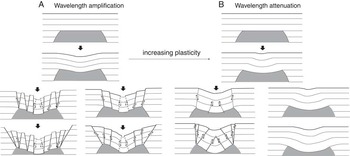
The prevalence of deformational structures type seems to be related to the fundamental aspects of folding. The ratios of layer thicknesses, viscosities and densities, the orientation of mineral grains during deformation, the mechanical properties of the interfaces, and the proportion of sideways pressure force to the gravitational force are the main factors that govern passive folding of multilayered rocks and so the geometry of folding and the ductile-brittle transition (Biot et al., Reference Biot, Odé and Roever1961; Ramsay and Huber, Reference Ramsay and Huber1987; Ranalli, Reference Ranalli1995; Stüwe, Reference Stüwe2007). These conditioning factors will control the shape of a sag basin, the wavelength and amplitude of folds, and the location, number, and type of faults. Despite the large number of possible geometric combinations and assuming dissolution concentrates in the top of the diapir, there are two main possible structural configurations expected in dissolution-collapse diapirs that depend on the rheological properties of the overburden (Fig. 9). When the overlying strata are made up of a set of competent beds (Fig. 9A), the layers start to buckle to form a parallel fold with constant curvature reaching the breaking point. Under increasing tangential longitudinal strain, the rock fails by the development of either conjugated shear fractures or subvertical normal faults in relation to extension at the margins. Contractional antithetic reverse faults (bending moment faults) may develop because of space limitation in the inner part. As bending proceeds and the area affected by subsidence increases, normal faults rotate to finally dip outward (Dias and Cabral, Reference Dias and Cabral2002). In a final stage, normal faulting propagates farther away from the diapir contact by low-dipping fracture planes. In contrast, if the overburden is mainly constituted by low mechanical strength and ductile beds, plasticity increases, layer parallel shear dominates, and passive bending is accommodated by disharmonic folding and wavelength attenuation (Fig. 9B). The lower beds may fail in the inner arc by layer contraction faults that attenuate upward, and subvertical inward-dipping faults may develop at the outer margin in an advanced subsidence stage.
Schematic sketches of collapse structures depending on the rheology of the overburden, increasing plasticity, and wavelength attenuation. (A) Wavelength amplification. (B) Wavelength attenuation.

The structural features of collapsed-salt anticlines in the Paradox Basin (Gutiérrez, Reference Gutiérrez2004; Guerrero et al., Reference Guerrero, Brunh, McCalpin, Gutiérrez and Willis2015) and Salinas de Oro salt diapir fit better with the geometric configuration of model (Fig. 9A) because the overburden is stiffened by a limestone sequence. In contrast, physical models often fit the extensional ductile model shown in Figure 9B because the analog overburden used in the rigs on top of balloons or mounds of silicon tend to be unconsolidated sandy and clayey sediments with low shear strength.
Origin of the Andia Fault Zone and Etxauri Fault
The geomorphic mapping of the Salinas de Oro salt diapir shows that radial faults disrupt the drainage network, displace Quaternary deposits, and crosscut active ring failure faults and graben structures. These are lines of evidence that suggest that the salt diapir is still rising by passive diapirism. However, where the salt withdrawing from, and what is driving the continuing movement of salt.
The first investigations considered the AFZ to be the surface expression of the motion of the Pamplona transfer basement fault (Liesa, Reference Liesa1999), whose strike at depth is approximately parallel with the Salado Creek syncline (Larrasoaña et al., Reference Larrasoaña, Parés, Millán, del Valle and Pueyo2003). Later, from paleomagnetic studies, Larrasoaña et al. (Reference Larrasoaña, Parés, Millán, del Valle and Pueyo2003) indicated that the Paleocene and Middle Eocene strata on both sides and across the Pamplona Fault did not undergo vertical axis rotation and so disregarded the strike-slip movement of the fault and transfer-related genesis for the AFZ. Based on the “hanging-wall drop model,” Elliott and Johnson (Reference Elliott and Johnson1980) concluded that the AFZ was not related to the motion of the Pamplona Fault but to the perpendicular extensional failure of the south Pyrenean thrust front during the Oligocene and Miocene compression stage. According to these researchers, the thicker Mesozoic and Tertiary sequence in the hanging wall of the Pamplona Fault involved a lateral variable thickness between the roof and floor of the thrust and consequently the development of normal faults parallel to the tectonic transport direction. There are several arguments against this tectonic explanation. First, despite the Pamplona Fault being more than 120 km long, normal faulting in the hanging wall is exclusively limited to the southeast of the Salinas de Oro salt diapir along 17 km of the fault trace. Second, drainage disruption, displacement of Quaternary piedmonts, the occurrence of nonkarstified, fresh-looking scarps, and the tilting of trees and buildings indicate recent motion of both the Iturgoyen and Riezu faults. Following Larrasoaña et al.’s (2003) hypothesis, the area should be still undergoing north–south compression to explain the present-day activity on the AFZ. In contrast, geodetic results (Nocquet and Calais, Reference Nocquet and Calais2004; Asensio et al., Reference Asensio, Khazaraddze, Echeverria, King and Vilajosana2012; Nocquet, Reference Nocquet2012), the compilation of a complete moment tensor catalog of Pyrenean earthquakes, and the analysis of focal mechanisms (Chevrot et al., Reference Chevrot, Sylvander and Delouis2011; Rigo et al., Reference Rigo, Vernant, Feigl, Goula, Khazaradze, Talaya and Morel2015) support the idea that the Pyrenees are currently experiencing a northeast-directed extensional deformation (De Vicente et al., Reference De Vicente, Cloetingh, Muñoz Martin, Olaiz, Stich, Vegas, Galindo- Zaldivar and Fernández-Lozano2008; Chevrot et al., Reference Chevrot, Sylvander and Delouis2011; Vernant et al., Reference Vernant, Hivert, Chéry, Steer, Cattin and Rigo2013) invalidating the view of Larrasoaña et al. (Reference Larrasoaña, Parés, Millán, del Valle and Pueyo2003) that there is thrust front collapse.
On the other hand, this extensional stress direction is expected to cause northwest–southeast extensional structures, whereas the northeast- and north-trending structures of the AFZ show an oblique orientation to the former stress tensors also invaliding their extensional tectonic origin. GPS measurements of deformation across the 150-km-wide Pyrenean range determine that the relative horizontal motion between European and Iberian plates responsible for Pyrenees extension is currently between 0.5 and 0.2 mm/yr depending on the segment and the measuring time period (Nocquet and Calais, Reference Nocquet and Calais2004; Asensio et al., Reference Asensio, Khazaraddze, Echeverria, King and Vilajosana2012; Nocquet, Reference Nocquet2012; Rigo et al., Reference Rigo, Vernant, Feigl, Goula, Khazaradze, Talaya and Morel2015), whereas the current vertical displacement of Iturgoyen Fault alone was estimated at around 24 mm/yr. This value is 5 to 12 times higher than the rate of plate motion and supports a nontectonic genesis. Finally, the eastern faults of the AFZ connect with Salinas de Oro radial faults suggesting a coeval formation and genetic relationship between the AFZ and Salinas de Oro salt diapir (Gil and Liesa, Reference Gil and Liesa1994; Liesa, Reference Liesa1999).
The following evidence points to the AFZ as the main withdrawal feeding area of Salinas de Oro diapir: (1) the geographic location of the AFZ around the Salinas de Oro diapir, (2) the spatial connection between extensional faults of AFZ and radial faults of the salt diapir roof, (3) throw attenuation of AFZ deformational structures away from the diapir, (4) rising of the Salinas de Oro salt diapir from fault crosscutting relationships, and (5) drainage disruption and offset of Quaternary deposits in radial and AFZ grabens. Subsurface data in the Cubeta Alavesa suggest that differential loading is the dominant force driving salt expulsion and is responsible for gravity-driven extension and brittle deformation of the AFZ. According to seismic profiles (IGME, 1990a; Serrano and Martínez del Olmo, Reference Serrano and Martinez del Olmo1990), the top of the Paleozoic basement underlying Triassic salt dips ~10° to the northeast favoring salt flow toward the Salinas de Oro diapir. Besides, the movement of salt is enhanced by lateral variations in the overburden thickness. The Mesozoic and Tertiary sequences are around 4000 and 2500 m in the AFZ and bottom of the Salado Creek valley close to Alloz Reservoir, respectively. This 1500 m difference in thickness exerts a strong differential lithostratigraphic pressure and consequently creates a significant hydraulic head gradient toward the valley.
Subsurface data around the Salinas de Oro diapir demonstrate considerable difference in the thickness of Triassic salt at both sides of Pamplona Fault because it was used as a main detachment level during Alpine compression that aided salt migration into the diapirs (Larrasoaña et al., Reference Larrasoaña, Parés, Millán, del Valle and Pueyo2003). To the east of the Salado Creek syncline, in the eastern block of the Pamplona Fault, borehole data indicate that Triassic rocks are <500 m in thickness and almost devoid of halite with just sporadic interbeds around 2–5 m thick (IGME, 1990a, 1990b). To the west of the Salado Creek syncline, in the western block of the Pamplona Fault, seismic profiles (IGME, 1990a, 1990b) and gravimetric data (Pinto et al., Reference Pinto, Casas, Rivero and Torné2005) demonstrate that Triassic facies thickness is more than 2500 m at the fault contact and decreases progressively to west. To the west of the Ibiricu Fault, Triassic rocks have been reduced to <500–1000 m thick and are either devoid of salt or there is a little salt left. According to Hudec and Jackson (Reference Hudec and Jackson2007), salt flow stops when salt expulsion reduces the salt layer below a threshold thickness. Once it is reached, friction forces related to boundary dragging along the top and bottom surfaces of the salt bed overcome differential loading. The degradation of the Zumbelt, Iranzu, and Ibiricu fault scarps and the existence of undeformed Quaternary alluvial and slope deposits covering the fault plane point to their inactivity or very low slip rate. This reinforces the idea that halite may be almost exhausted and probably reaches its creeping threshold thickness to the west of Ibiricu Fault. Salt thickness distribution at depth explains the following: (1) why salt-withdrawal structures are seen only in the western block of the Pamplona Fault at the AFZ and are absent from the eastern block of the Pamplona Fault where Triassic formations are devoid of salt; (2) their linear trend conditioned by the geographic orientation of the Pamplona basement fault; and (3) the lower activity of the western AFZ faults in response to a progressive decrease of salt thickness.
A priori, the Etxauri Fault could be considered as the most important radial fault on the eastern diapir flank. However, several arguments demonstrate that the Etxauri Fault has to be considered a salt withdrawal–induced fault rather than a radial fault. In contrast to the rest of radial faults whose throw decreases away from the diapir, the vertical displacement of the Cretaceous and Tertiary sequence associated with the motion of the Etxauri Fault increases from 70 m at the limestone escarpment to >280 m farther to the east (Fig. 3, CS2). The Etxauri and Ibero village springs located at the fault plane and 5 km to the east of the diapir discharge 250 L/s of sodium chloride–rich waters reaching conductivity values of 2.982 μS/cm and 4.490 μS/cm, respectively (Confederación Hidrográfica del Ebro, 2016). These highly saline brines demonstrate that the fault plane of the Etxauri Fault must reach the Triassic saline strata probably more than 3 km deep allowing the rise of groundwater from the Triassic aquifer. Two shallow earthquakes with focal depth at 3 km and magnitude greater than 3 (Ciriza and Etxauri earthquakes with M w 3.6 and 4.1, respectively) might be attributed to the motion of the Etxauri Fault in 2013 (Faci et al., Reference Faci, Galé, Gil, Lago, Larrasoaña, Piedrafita and Aretxabaleta2013). Because the Paleozoic basement is located by seismic reflection profiles between 2 and 1.5 km deeper than the hypocenters at this point (IGME, 1990a), it seems that earthquakes are not related to basement fault motion. Instead, they can be attributed to the migration of deep salt. Earthquakes and water conductivity values together with the displacement of tuffaceous terraces, the reorientation of the Arga River channel parallel to the fault scarp, the existence of open fissures in bedrock, and concentric fracturing overprinting all indicate continued flow of salt into the Salinas de Oro diapir. The estimated slip rate of the Etxauri Fault of 0.12–0.16 mm/yr is close to the overall extensional deformation value of the Pyrenees (Rigo et al., Reference Rigo, Vernant, Feigl, Goula, Khazaradze, Talaya and Morel2015). This points to the nontectonic genesis of the Etxauri Fault and supports salt migration into the diapir for the last 151–178 ka. Future local geodetic measurements and gravimetric data will corroborate the location and extension of the feeding areas; the slip rate of concentric, radial, and salt-withdrawal faults; and the passive diapirism uplift model.
Rising versus subsidence
The final shape of a diapir mainly depends on the flow of salt and the rates of downward dissolution, erosion, and aggradation (Vendeville and Jackson, 1992a, Reference Vendeville and Jackson1992b; Hudec and Jackson, Reference Hudec and Jackson2007). In continental settings where salt diapirs may be responsible for the highest peaks, aggradation is often limited. In these cases, the rise of the salt diapir crest is exclusively counterbalanced by salt dissolution and erosion. Once doming triggers the development of radial faults and salt is exposed to the surface, dissolution starts and the overlying strata tend to subside by a combination of passive bending and collapse. The development of ring-collapse faults enhances salt dissolution processes in a feedback mechanism that results in a continuous settlement of the salt diapir crest to finally become an annular depression covered by broken strata and insoluble residue when dissolution and erosion exceed salt diapir growth. In contrast, salt may overflow its margins and extrude where salt flow outpaces erosion and dissolution (Talbot, Reference Talbot1998; Talbot and Aftabi, Reference Talbot and Aftabi2004).
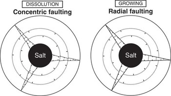
Whether salt dissolution and diapir growth occur at the same time is an important question. Geophysical data of prekinematic, synkinematic, and postkinematic strata and thickness variation demonstrate that salt diapir growth is often episodic with rising phases alternating with pauses (for examples, see Hudec and Jackson, Reference Hudec and Jackson2011). Pursuing this line of thought, recent paleoseismological studies of subsidence structures in Spain (Gutiérrez et al., Reference Gutiérrez, Carbonel, Guerrero, McCalpin, Linares, Roque and Zarroca2012; Carbonel et al., Reference Carbonel, Gutiérrez, Linares, Roqué, Zarroca, McCalpin, Guerrero and Rodríguez2013), Colorado (Gutiérrez et al., Reference Gutiérrez, Carbonel, Kirkham, Guerrero, Lucha and Matthews2014), and Utah (Guerrero et al., Reference Guerrero, Brunh, McCalpin, Gutiérrez and Willis2015) demonstrate that normal, reverse, and flexural-slip faults related to interstratal dissolution of evaporites also show episodic displacements. Thus, because salt rise and dissolution may also vary in time with alternating episodes of activity and calm, the shape of the diapir and fault crosscutting relationship may become very complex (Fig. 10). During quiescent salt diapir growth phases, salt dissolution processes will cause the roof to subside by the development of ring monoclines and concentric faults that will crosscut previous radial structures. In contrast, when the salt stock is actively growing and salt dissolution is negligible, radial grabens and faults will overprint ring-concentric faulting. Ring faults may even be covered by alluvium in the radial grabens bottom and so disappear from the surface in response to significant vertical displacements. When salt dissolution and diapir growth happen at the same time, the fault relationship will be controlled by the ratio between both processes because subsidence may counterbalance or exceed salt flow. As salt dissolution is also spatially variable, fault overprinting may differ in every sector of the salt diapir.
Sketches showing the relationship between radial and concentric fault patterns depending on the predominance of salt flow or dissolution subsidence.

In the Salinas de Oro salt diapir, the net vertical displacement related to subsidence of Middle Eocene limestones and marls using the base of the Paleocene sequence as a marker was estimated to be around 90 m (Fig. 3, cross section CS1). Nevertheless, the crest of the salt diapir is today a topographic depression 300 m bellow the surrounding annular limestone escarpment. Thus, this relief difference mainly relates to erosion rather than salt dissolution. This value of vertical displacement yields an average subsidence rate of 0.002 mm/yr considering a time interval of 37 Ma for the deformation (top of the Middle Eocene marls). Nevertheless, the activity of sinkholes at the bottom of the valley, the opening of ground fissures in the hanging wall of concentric normal faults, and the disruption of the drainage network point to a current subsidence rate being higher than the average and provide evidence of the episodic behavior of the salt dissolution phenomenon.
The Middle Eocene limestone escarpment that has uplifted 150 m from its surroundings provides an average growth rate of around 0.004 mm/yr over the past 37 Ma. This value, which is double that of the subsidence rate, has to be considered as a minimum because salt flow is partly compensated by dissolution and erosion. The estimated slip rate of the Iturgoyen salt-withdrawal fault alone in the AFZ is 600 times higher than the average growth rate of the diapir. This difference reinforces the idea that salt flow into the diapir is currently much faster. Radial grabens offsetting Quaternary deposits, disrupting the drainage network, and overprinting ring faults demonstrate that salt flow into the diapir exceeds dissolution subsidence.
CONCLUSIONS
The geomorphology and fracture pattern of the Salinas de Oro salt diapir result from upward salt flow, salt dissolution, and erosion during the last 37 Ma. Karstic subsidence and erosion have transformed the salt diapir into a deep topographic depression surrounded by an annular limestone escarpment 300 m above the top of the salt diapir. Sinkholes up to 310 m in diameter and 70 m deep act as swallow holes disrupting the local drainage. The roof of the salt diapir downsags into the center of the diapir leading to an annular monocline that is broken by a sequence of fresh-looking, inward-dipping concentric normal faults. Graben structures and a 9.5 km and up to 200-m-wide concentric keystone graben offset the diapir crest >40 m, give way to elongated closed depressions, and disrupt the drainage network. This structural configuration is expected of competent roof strata where subsidence is accommodated mainly by collapse. The net vertical displacement because of dissolution reaches around 90 m yielding an average subsidence rate of 2 m/Ma. However, the current activity of sinkholes and concentric faults, the existence of open cracks on bedrock and Quaternary pediment deposits, and drainage disruption point to a much faster rate for much of the Quaternary and suggest that most of the dissolution is compensated by salt flow.
The episodic rise of the Salinas de Oro diapir is responsible for the reactivation of radial faults and grabens that crosscut the keystone graben and most of the subsidence-induced concentric faults. This overprinting relationship indicates that the growth rate is faster than the dissolution subsidence rate. The motion of radial faults is causing the displacement of slope and pediments deposits, the development of sinkholes and grooves along the hanging wall, and the diversion and truncation of the drainage network leading to abandonment reaches and hanging creeks.
The salt feeding the growing diapir comes mainly from the AFZ, which is considered to be a collapse fault system caused by evacuation of autochthonous salt. Gravity-driven extension of the AFZ is accommodated by a stepped sequence of >10-km-long grabens and normal faults that have been active from the Middle Eocene to the Quaternary. They are responsible for the vertical offset of the cover bringing Cretaceous marls into contact with Middle Eocene limestones. Subsurface data suggest that differential loading caused by a lateral overburden thickness variation of around 1500 m above an inclined to the northeast basement is the driving force responsible for salt expulsion from the AFZ into the Salinas de Oro diapir. Unfortunately, it is difficult to ensure which is the critical salt thickness in the AFZ below which salt flow is restricted because of viscous shearing along the boundary salt layers. The western faults of the AFZ (Zumbelt, Iranzu, and Ibiricu) are probably inactive because that threshold thickness has been reached. In contrast, the eastern Iturgoyen and Riezu faults are responsible for trees tilting, façades cracking, offset of Quaternary deposits, and drainage disruption indicating current deep salt flow.
Field mapping of the Salinas de Oro salt diapir demonstrates that salt dissolution and upward flow may either alternate or happen at the same time to control the final shape of a salt plug. Concentric faulting related to subsidence will overprint radial faults when the rate of salt dissolution exceeds the diapir rise rate and vice versa. The configuration of concentric structures depends on the physical properties of the salt diapir roof. Where the overlying strata are mainly competent beds, collapse processes are dominant and the deformation is accommodated by a stepped sequence of ring-shaped, inward-dipping normal faults. In contrast, a plastic overburden bends to develop a well-developed annular monocline affected by reverse concentric faulting.
ACKNOWLEDGMENTS
The work has been partially financed by project CGL2013-40867-P (Ministerio de Economía y Competitividad, Spain). The author acknowledges the thorough review of Lewis Owen (Editor), Jaime Urrutia Fucugauchi (Associate Editor), Christopher J. Talbot (reviewer), and anonymous reviewers.