Introduction
An antenna is the most essential element of any communication systems. It is capable of signal transmission into space and vice versa. Many years ago simple antenna structure was used in a mobile communication system. This communication technology is known as single input single output. The drawback of this system is that fading arises due to multipath propagation and the data rate decreases [Reference Chouhan, Panda, Gupta and Singhal1]. Multiple input multiple output (MIMO) communication technique is used in modern days to reduce this fading problem.
MIMO is a good communication technique that offers high data rates, high channel capability, performance, and efficiency, and has the best quality service in the wireless world [Reference Malviya, Panigrahi and Kartikeyan2]. MIMO antenna requires many antennas at the transmitter, and on the receiver side a mutual coupling problem arises. Mutual coupling degrades the performance of an antenna.
To reduce the mutual coupling problem and improve the isolation among antenna elements in MIMO, various isolation techniques are used that have been investigated by researchers, like decoupling structure, parasitic elements, neutralization lines, slot etching, defected ground structure, metallic stubs, metamaterial structure, etc. [Reference Chouhan, Panda, Gupta and Singhal1–Reference Agrawal and Gupta3]. A compact MIMO antenna was designed that has used the neutralization isolation approach to reduce mutual coupling and provided >12 dB isolation [Reference Serghiou, Khalily, Singh, Araghi and Tafazolli4]. A T-shaped ground stub was placed between antenna elements to improve isolation and impedance matching and it achieved high isolation >20 dB in the whole operating band [Reference Saurabh and Meshram5]. Another technique like a combination of parasitic element and T-shaped structure is used in the ground plane to achieve better isolation >11 dB throughout the operating band and it also had a wideband. The modified feed line is also used for impedance matching [Reference Chouhan, Panda, Kushwah and Mishra6]. The balanced slot mode was used in an MIMO antenna and provided high isolation >17.5 as well as high total efficiency >62%. The operating band of this MIMO antenna is 3.4–3.6 GHz and it showed a low envelope correlation coefficient (ECC < 0.5). This antenna design is used in mobile applications [Reference Li, Luo and Yang7]. The self-isolated structure is reported which gives isolation of >19.1 dB and is very compact and used in mobile applications [Reference Zhao and Ren8]. A meander line MIMO antenna is investigated for wireless local area network (WLAN) application which has ring-shaped ground and gives low-profile design and sharp edge for better isolation [Reference Chouhan, Panda, Gupta and Singhal9]. The orthogonal mode method is also presented for reducing the mutual coupling effect between closely placed antenna elements. This method helps to obtain high isolation of >17 dB and a low ECC of 0.06 [Reference Sun, Feng, Li and Zhang10]. A compact microstrip antenna with a steady radiation pattern over the broadband range is described and it has a 5 dBi average gain, steady radiation characteristics, low cross-polarization, and minimal back lobes, making it suitable for 5G wireless communication systems [Reference An, Li, Fu, Ma, Chen and Feng11]. Additionally, monopole-like radiation patterns are achieved, which can be used for mobile communications [Reference Zhang, Liu, Wang, Gan, Wang and Sun12]. An MIMO system operates in the 3.5 GHz (3.4–3.6 GHz) band with a −17 dB isolation and also has high gain, good channel capacity, and minimal ECC (0.1) [Reference Ren, Zhao and Wu13]. Mutual coupling between neighboring radiators has been greatly decreased owing to the incorporated parasitic structure. At the resonance frequency (3.6 GHz) they consist of more than 70% overall efficiencies. Furthermore, the radiators of the suggested MIMO mobile-phone antenna has attained above 75% radiation characteristics and 60% total efficiency characteristics for the frequency range of 3.4–3.8 GHz (5G operation band). The designed scheme has enough features for 3.6 GHz applications and could be a good candidate for 5G mobile applications [Reference Chen, Chou, Hsu and Li14]. To attain wideband and great isolation, a parasitic patch and a defected ground structure are employed together. Mutual coupling among antenna sets is diminished by engraving slits on the ground. The suggested antenna includes the frequency bands n77/n78/n79 and WLAN 5 GHz band entirely, with a bandwidth of 3.3–5.95 GHz (57.3%). Aside from that, it has good isolation, efficiency, and ECC [Reference Hei, He and Li15]. A broadband 4 MIMO antenna with good isolation in a compact package is presented [Reference Kumar Saurabh, Singh Rathore and Kumar Meshram16]. Diverse antennas with high isolation of >20 dB dual-band (2.195–2.593 GHz and 5.730–5.918 GHz) for WLAN applications are investigated [Reference Singh, Pandey, Bharti and Meshram17]. It is aimed to introduce an MIMO antenna with a superior isolation of >22.5 dB. Two G-shaped components in the top layer, two reversed L extend branches, and a T slot carved inside the ground are used to minimize mutual coupling [Reference Xia, Chu and Li18]. The described antenna performs well in terms of ECC < 0.2, isolation >15 dB, and a radiation characteristic which is 80% [Reference Thakur, Jaglan, Gupta and Kanaujia19]. The suggested antenna's key features are its excellent isolation >17 dB, minimal ECC (0.047), high gain > 6 dB as well as successful diversity ability [Reference Suriya and Anbazhagan20]. Throughout the operating bandwidth, the antenna has a consistent radiation pattern. Furthermore, the ECC of the designed antenna is <0.25, which is sufficient to maintain a high channel capacity [Reference Gorai, Dasgupta and Ghatak21]. An MIMO multiband antenna is presented. It includes Wi-Fi/WiMAX/Bluetooth, as well as C-band applications. Without employing any isolation elements, more than 10 dB isolation is accomplished in all four operating bands [Reference Chouhan, Panda, Kushwah and Singhal22]. For good isolation, larger bandwidth, and pattern variation, a distinct decoupling design is implemented [Reference Agrawal, Gupta and Chauhan23]. The suggested antenna has better isolation, low ECC, and better efficiency for the 3.3–4.2 GHz operating band [Reference Chang and Wang24]. For 5G purposes, a sharing aperture S/K-band meta surface-based antenna is designed. Over the S-band (3.2–4.05 GHz) and the K-band (25.22–26.46 GHz), the designed antenna exhibits −10 dB reflection coefficient bandwidth capacities of 23.45 and 4.8%, correspondingly, with actual gains of 7.52–10.88 and 21.3–22.4 dBi [Reference Li and Chen25]. The numerous antennas [Reference Singhal, Singh and Singh26–Reference Dikmen, Çimen and Çakır29] utilize an octagon-shaped structure, enabling supports for broadband and ultra-wideband purposes that have at least 10 dB isolation. An artificial neural network [Reference Alkurt, Ozdemir, Akgol and Karaaslan35–Reference Alkurt, Karaaslan, Furat, Ünal and Akgöl37] is used to obtain desired radiation characteristics.
In this paper, a two-element slotted octagon-shaped antenna operating in 5G sub-6 GHz band at 3.1–4.5 GHz is presented. A T-formed isolation structure is placed at the ground plane to minimize mutual coupling between MIMO antennas. The proposed MIMO antenna has physical dimensions of 55 × 38 mm2 and an ECC or correlation of 0.0004 over the entire operating band. CST studio suite simulation tool is used to design and analyze the proposed antenna.
Antenna design
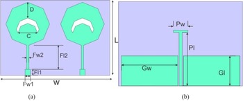
The front and back schematic structure of the proposed two-element antenna with optimized dimensions is shown in Fig. 1. Also, the design steps view of the proposed antenna is illustrated in Fig. 2. The proposed antenna is designed in three steps. At first, design microstrip feed line, and after that an octagon-shaped radiator of radius 10.98 mm is designed. At last, one octagon-shaped slot with a radius of 4.92 mm is loaded in the middle. The T-shaped structure between the ground is used to improve the isolation between two ports. The design parameters are obtained by standard formula of feed line and circular patch and then optimized by the CST tool.
Proposed antenna: (a) front and (b) back schematic.

Design steps of the proposed antenna.

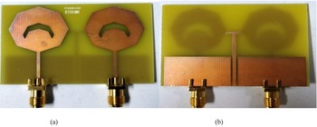
The suggested MIMO antenna's fabricated top and back views are depicted in Fig. 3. In Table 1, the antenna geometry's optimal measurements are provided. The proposed MIMO antenna is formed on an FR4 dielectric which is easily available and low cost, which has a relative permittivity of 4.3 and a loss tangent of 0.025. The substrate has a size of 55 mm × 38 mm. The top section of the substrate is etched by two-octagon radiators. A T-formed isolating structure has been placed on the lower side to minimize the consequences of mutual coupling between the MIMO radiating patch. To achieve lower dimensions of the MIMO antenna design, a partial ground is included in the design.
Proposed octagon-shaped MIMO antenna: (a) top view and (b) back view.

Optimized dimensions

Result analysis
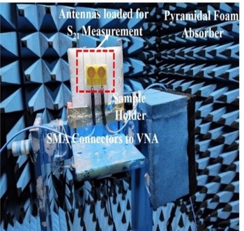
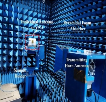
The simulation and measurement of S-parameters of the designed MIMO antenna are conducted by using the CST suite tool and vector network analyzer (VNA). The simulated and experimented resonance frequencies of the designed MIMO antenna are the same. The simulated return loss S 11 is −40 dB and the measured return loss is −36 dB at a resonance of 3.6 GHz, as shown in Fig. 4. The isolation between port-1 and port-2 is denoted by S 21. The simulated and experimental S 21 are >19.5 and 20 dB, respectively, as shown in Fig. 5. The band of the designed antenna is 3.1–4.5 GHz. The little discrepancies arise in experimental and simulated measurements due to manufacturing inaccuracies. The S-parameters measurement setup by VNA is shown in Fig. 6 and the far-field gain measurement setup is shown in Fig. 7.
Simulated and measured result of S 11.

Simulated and measured result of S 21.

S 11 and S 21 measurement setup by VNA.

Gain measurement setup.

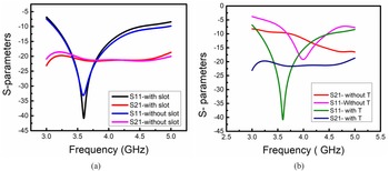
The S-parameters’ results of full octagon and slotted octagon and with T-shaped and without T-shaped element are presented in Fig. 8. It is clearly shown that good isolation and return loss are observed with the proposed design. The return loss with is −40.8 dB at resonance frequency whereas return loss without slot is −33.15 dB; therefore, return loss has improved. Similarly, isolation also improved slightly by 1.5 dB than without slot.
Comparison of (a) with and without slot and (b) with and without T-shaped.

The comparison of the same is given in Table 2. At the initial stage full octagon geometry was chosen but for the improvement of return loss, isolation, and ECC a slot of the same shape is created.
Comparison of with and without slot and T-shaped

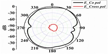
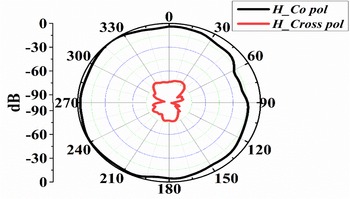
For E- and H-field radiation patterns, a far-field evaluation of the prototype system was performed. Further with the use of positioning equipment, the antenna was installed horizontally as well as vertically in an anechoic chamber to evaluate the E- and H-field values. To exhibit the radiation pattern of the antenna, the E-field for ϕ = 0° and H-field for ϕ = 90° have been provided. The E-field co-polarization and cross-polarization distribution of a proposed antenna at 3.6 GHz is depicted in Fig. 9. The major lobe has a direction of 230° and a magnitude of 17.8 dBV/m. Fig. 10 depicts the H-field at 3.6 GHz in the same way. The major lobe's direction and magnitude are 170° and 16.4 dBV/m, correspondingly. The 3-dB angular width is 106.2°.
E-field co-pole and cross-pole distribution of MIMO antenna.

H-field co-pole and cross-pole distribution of MIMO antenna.

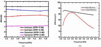
Fig. 11. shows the mean effective gain (MEG) value and the antenna efficiency of the MIMO antenna. A MEG is another performance factor of an antenna that is a fraction of the MIMO antenna array's average received signal strength to its average incident power. Each antenna's average received power intensity can be computed by using MEG. To study the diversity performance of isotropic and Gaussian/uniform mediums, the MEG is estimated through CST simulation models for various values of cross-polarization ratio (XPR). While XPR is equal to 0 dB in an isotropic environment, the MEG is −3 dB and it remains constant over the whole band. The MEG is in the range of −4.7 to −5 dB at XPR equal to 6 dB. MEG values for Gaussian medium with XPR = 0 dB and XPR = 6 dB, accordingly, are −3.5 to −3.9 dB and −6.8 to −6.85 dB for the depicted band. Fig. 11(a). presents all of the MEG data for both isotropic and Gaussian environments. Table 3 shows simulated MEG values of the designed antenna at a resonance frequency of 3.6 GHz for both isotropic and Gaussian mediums.
Proposed MIMO antenna: (a) MEG value and (b) antenna efficiency.

MEG simulated comparison result of designed MIMO antenna at the resonance frequency

The antenna efficiency of the proposed MIMO antenna varies with frequency, as illustrated in Fig. 11(b). The radiation efficiency of the antenna is defined as the ratio of transmitted signal strength to received signal strength while total efficiency is calculated by multiplying radiation efficiency and mismatched loss. Radiation efficiency and total efficiency vary from 90 to 93% and 80 to 91%, respectively, in the operating band 3.1–4.5 GHz. The radiation efficiency is 92% at resonance, while the total efficiency is 91%.
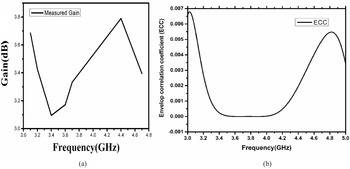
Fig. 12. shows the gain and ECC of the proposed MIMO antenna. Far-field gain is examined in an anechoic laboratory as shown in Fig. 12(a); it is found to be between 3.09 and 3.79 dBi throughout the operating range. At 3.6 GHz resonant frequency, the observed gain of the MIMO antenna is 3.17 dBi.
Proposed MIMO antenna: (a) gain and (b) ECC.

Fig. 12(b). depicts the simulated ECC result. It is <0.004 in the entire frequency spectrum, indicating that MIMO has successful diversity functionality. A 0.5 limit has been set by ITU (International Telecommunication Union). ECC should be <0.5 to improve diversity performance. The result of 0.004 indicates an extremely low correlation between the antenna parts.
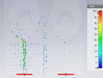
Surface current is studied at a 3.6 GHz resonance to minimize the influence of mutual coupling. Fig. 13. shows the surface current distribution of the MIMO antenna with T-formed structure. It is placed at the ground plane between antenna elements to lower the level of surface current between ports 1 and 2 and the isolation achieved is 20 dB in the entire operating band.
Surface current distribution of MIMO antenna.

Table 4 compares the proposed antenna design to the existing MIMO antenna design with sub-6 GHz band for 5G application. The sub-6 GHz bands for 5G that have been promoted in many countries are 3.1–3.55, 3.4–3.8, 3.7–4.2, 4.8–5, and 5.15–5.925 GHz. The proposed MIMO antenna's band is 3.14–4.5 GHz that is within the abovementioned 5G frequency band. The two-element antennas with operating band range are 3.34–3.87 and 3.3–4.2 GHz are described in [Reference Saurabh and Meshram5] and [Reference Chang and Wang24], while the proposed two-element MIMO antenna's operating band range is 3.14–4.5 GHz which is quite large and ECC is lower compared with the existing MIMO antenna designs. MIMO antennas proposed in [Reference Serghiou, Khalily, Singh, Araghi and Tafazolli4, Reference Li, Zhang, Wang, Chen, Chen, Li and Zhang30, Reference Desai, Patel, Upadhyaya, Kaushal and Dhasarathan31, Reference Wong, Chang, Chen and Wang32] have dual-band. The efficiency of MIMO antennas [Reference Saurabh and Meshram5, Reference Wong, Chang, Chen and Wang32] are better than the proposed antenna, but in contrast the proposed antenna has good return loss, isolation, and ECC. The antennas of [Reference Sun, Feng, Li and Zhang10] and [Reference Ren, Zhao and Wu13] are of four-element while the proposed one is a two-element having lower ECC and higher antenna efficiency. Some eight-element antenna designs were described in [Reference Li, Luo and Yang7, Reference Chen, Chou, Hsu and Li14, Reference Hei, He and Li15, Reference Ban, Li, Sim, Wu and Wong33]; the proposed MIMO antenna has a wideband, a very low ECC value, good isolation, diversity gain, and MEG while being small in size.
Comparison of the proposed antenna design to existing MIMO antenna designs with sub-6 GHz band

Conclusion
A two-element slotted octagon MIMO antenna is designed and discussed. The proposed MIMO antenna is presented with a sub-6 GHz band for 5G applications. It covers the operating band of 3.1–4.5 GHz and resonates at a 3.6 GHz frequency. It achieves good isolation, more than 20 dB in the whole operating band. Additionally, with the use of a T-shaped isolating structure between two radiators isolation is improved from 10 to 20 dB. The size of the proposed MIMO antenna is compact by using a partial ground structure with a physical dimensions of 58 × 27 mm2. Also, it provides very low ECC, wideband, high gain, and efficiency. The recommended antenna's feasibility for 5G applications is supported by a better agreement between simulated and measured results. The standard octagon-shaped antenna and proposed slotted antenna are also compared and merits of the same are discussed.
 Neetu Agrawal is currently associated with the Department of Electronics and Communication Engineering, Institute of Engineering & Technology, GLA University, Mathura. She obtained her B.E. from R.G.P.V. Bhopal (Madhya Pradesh), India, in 2002 and her M.E. in communication, control & networking (CCN) from the Madhav Institute of Technology & Science (MITS), Gwalior (Madhya Pradesh), India in 2008. Currently, she is pursuing Ph.D. at GLA University, Mathura (Uttar Pradesh), India. Her area of interest is MIMO antenna design for 5G applications. She has 15+ years of teaching experience.
 Manish Gupta is associated with the Department of Electronics and Communication Engineering, Institute of Engineering & Technology, GLA University, Mathura. He has 20+ years of teaching/research experience. He has published 50+ research papers in international and national journals and conferences. He obtained his Ph.D. in 2015 from University Engineering College, Rajasthan Technical University, Kota, Rajasthan, and his M.Tech. in 2006 from Uttar Pradesh Technical University, Lucknow, U.P., India. His research area is communication, signal and image processing.
 Sanjay Chouhan received his B.E. in electronics engineering from the Jawaharlal Institute of Technology, Borawan, Khargone (MP), India, his M.E. in electronics and telecommunication from Shri G. S. Institute of Technology and Science, Indore (MP), India, in 2008. He obtained his Ph.D. from Amity University Gwalior, India. His area of interest is in MIMO antenna design for wireless applications. He also won the best paper award in National Conference at Amity University Gwalior. He is a life member of the Indian Society for Technical Education (ISTE). He has published over 42 research papers in journals and conferences.