Introduction
Array antennas have been in use for several years on-board of telecommunication satellites [Reference Jacomb-Hood and Lier1, Reference Lier and Melcher2]. Most advanced active antenna architectures have been initially developed for military satellite applications where operational flexibility is a key requirement [Reference Fenech, Amos and Waterfield3]. In the last few years, as technology from the military sector makes itself commercially available, active array antennas are becoming very attractive, as they can respond to ever increasing demands from satellite operators [Reference Fenech, Amos, Moltzau and Guilleux4].
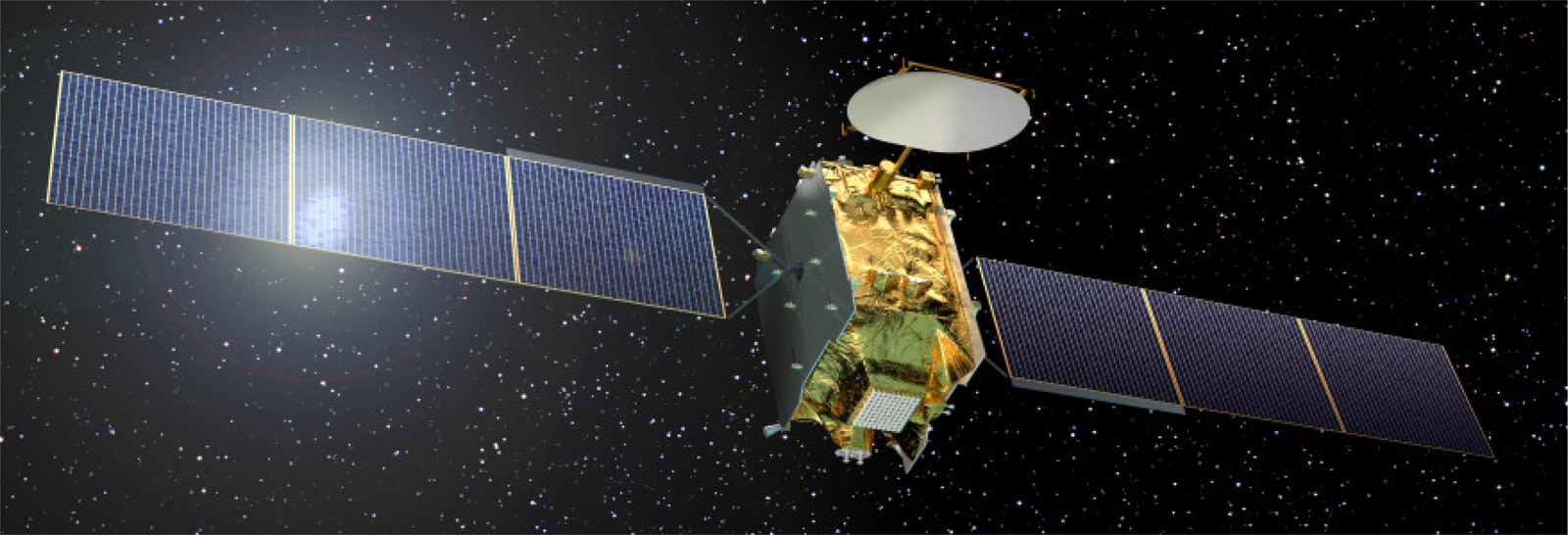
The need for in orbit re-configurability and flexibility in coverage, frequency, and power allocation, combined with secure connections and interference mitigation capabilities, are all key aspects that have seen an increasing demand for active array antennas on-board commercial telecommunication satellites. Eutelsat Quantum (https://www.eutelsat.com) is the first generation of a new class of universal satellites able to reprogram the satellite mission once the spacecraft is already in orbit and adapt it to quickly answer evolving market needs [Reference Fenech, Amos, Tomatis, Soumpholphakdy and Serrano Merino5] (Fig 1).
Eutelsat Quantum satellite artwork.

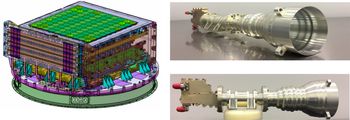
The quantum flexible payload includes an active Ku-band DRA Rx antenna operating in dual-polarization and providing reconfigurable multi-beam operation, with extended bandwidth and coverage shaping capability (Fig. 2).
Quantum Rx active DRA antenna (left, Courtesy of Airbus DS Spain) and antenna-radiating elements (right). ([Reference Pascale, Maiarelli, D'Agristina and Gatti10]; copyright EurAAP; used with permission)

Geo-location and interference mitigation capabilities are also implemented in the antenna system [Reference Montesano6]. These features allows us to monitor the position, power flux density, and polarization of interfering emitters within the whole fixed satellite service (FSS) band and to take corrective actions, such as antenna pattern nulling in the affected direction. All these features guarantee more traffic capacity, an unparalleled flexibility in coverage shaping, and an interference immune payload, currently not available in the European market. The Ku-band Rx antenna system is composed of a planar array antenna able to provide multiple beams, with full reconfiguration capability, by controlling the amplitude and phase of each antenna element independently. The beams can be configured as spot or shaped, depending on the desired scenario. The DRA is composed of radiating elements arranged on a square lattice with elements on the corners dedicated to the geolocation function. The outputs from the radiating elements are combined through an active beam-forming network. The front-end of the active antenna is composed of one low noise amplifier per element and per polarization, followed by digitally controlled RF attenuators and phase shifters for multiple beam operation [Reference Montesano, de la Fuente, Bustamante, Arenas, Peña, Gonzalez, Herrera, Pacheco, Martin, Naranjo, Dirube, Gualo, Marcos, Rodriguez, Gomez, Fenech, Amos, Piro, Le Pera, Roberts, Weinberg, Roux, Polegre, Otero, Gidney and Granell7]. The design of the Rx active antenna has been carried out by Airbus DS Spain and is described in the mentioned studies [Reference Montesano6–Reference Alvarez, Peña, Montesano, Zornoza, Rubio, Acevedo, Lopez-Mateos Paino, de la Fuente, Arenas, Mique and Villete8].
Antenna-radiating elements, subject of the current work, are dual linear polarization feed chains devoted to receive operation. Being the feed chain part of a large DRA architecture, composed of about 100 elements, size, mass, and similarity of performances become very critical requirements. The proposed design is able to provide high radiation efficiency and high gain, operating over the full FSS Ku-band, in a compact size and reduced axial length. This feature, in particular, makes the feed suitable to be integrated close to the active beamforming networks within the antenna architecture. In order to ease the connection with the active antenna front-end, subminiature version A (SMA) coaxial interfaces have been embedded as output ports of the radiating elements. Since the operative bandwidth required is about 10 times wider than in similar previously developed payloads [Reference Alvarez, Peña, Montesano, Zornoza, Rubio, Acevedo, Lopez-Mateos Paino, de la Fuente, Arenas, Mique and Villete8, Reference Gehring, Hartmann, Hartwanger, Hong, Ratkorn, Reiche and Wolf9], broad-banding and well controlled dispersion of the RF parameters represent the main challenges. A limited group-delay variation throughout the operative bandwidth and stringent transmission phase and amplitude tracking among the elements are also key design drivers.
In addition, each radiating chain shall embed a filtering section providing sharp rejection over the Ku Tx-band (10.7–12.75 GHz), to properly protect the active front-end stages.
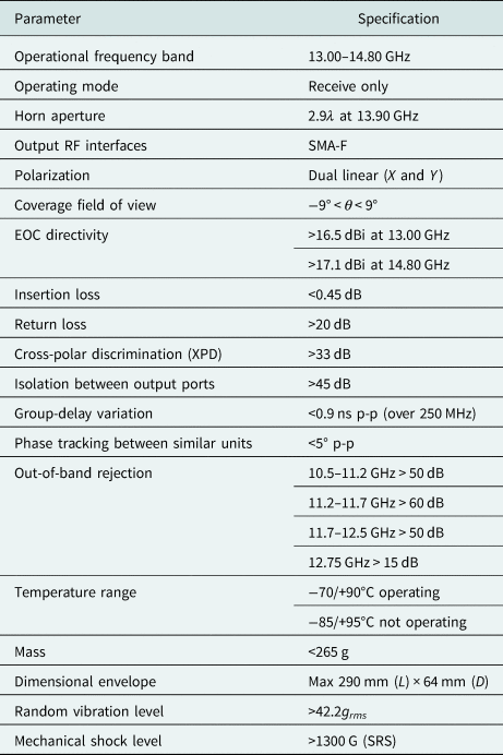
In Table 1, a summary of the main specifications of Ku-band Rx feed chains is reported.
Summary of Rx-radiating chains specifications

Feed chain RF design
The proposed design is a cascade of a thin-wall spline profile horn, a dual-polarization high-pass filter (HPF) in circular waveguide technology and an ortho-mode transducer (OMT) with standard SMA coaxial output ports [Reference Pascale, Maiarelli, D'Agristina and Gatti10] (Fig. 3).
Rx feed chain functional block schematic (left) and components identification (right).

Spline profile high-efficiency horn
Scanning capabilities and beam-shaping performances of active DRA antennas are directly dependent on the size and the spacing between the radiating elements. In these architectures, the number of active components required is multiplied by the number of radiating elements, contributing to volume, mass, and power budgets; complexity of the beamformers is also directly proportional to the number of elements.
Increasing the spacing between radiating elements allows reducing the number of units for a given DRA size, but undesired grating lobes can be generated in the antenna field of view. For geostationary satellites, where the maximum useful scanning angle is close to 8.7°, the condition for no grating lobes over the earth field of view set the maximum element spacing close to 3λ.
One of the drivers for the horn design is then to maximize radiation efficiency and directivity within the antenna field of view, with an aperture diameter close to 3λ. Due to the dual polarization operation, a high polarization purity is also an important requirement.
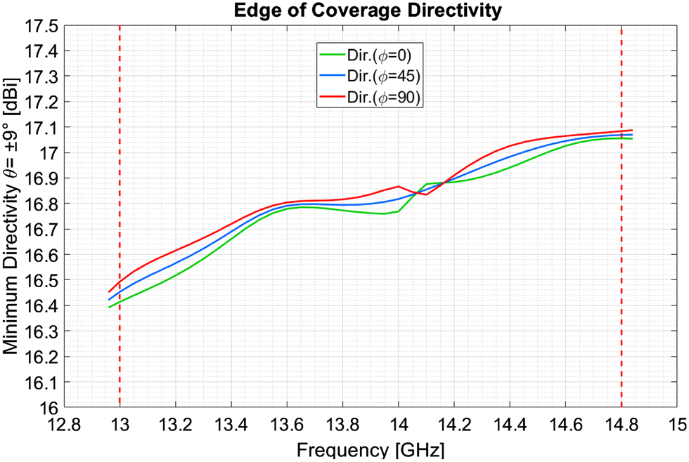
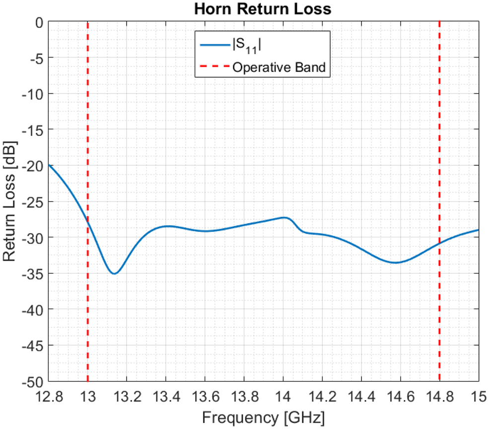
Corrugated horns can achieve very good cross-polar performances and co-polar pattern control over a wide bandwidth, but they are not very suitable for DRA applications, due to the intrinsically inefficient use of the radiating aperture and high manufacturing complexity introduced by the corrugations. Smooth wall horns, with a numerically optimized spline profile, are the best candidates to achieve high radiation efficiency, low return loss, and low cross-polarization over the full operating bandwidth, in a minimum axial length and reduced manufacturing complexity [Reference Granet, James, Bolton and Moorey11]. The horn profile must be optimized to generate both TE11/TM11 balanced modes and TE1 2/TM1 2 modes with proper amplitude and phase on the aperture, in order to achieve the required low-cross polarization and directivity performances. The solution developed is a horn with throat diameter Dt = 0.8λ and aperture diameter DA = 2.9λ. The cross-polarization level is always better than 35 dB below the co-polar peak and the return loss is better than 27 dB over 13% bandwidth. High aperture efficiency (better than 90%) and tight control of the radiation pattern are also achieved over the full operative bandwidth (Fig. 4).
Spline-profile horn – minimum EOC directivity (ϑ = 9°) versus frequency.

The preliminary design of the horn has been carried out using an “in-house” software tool based on the mode-matching method, driven by a genetic algorithm for the spline profile optimization. The input and aperture diameters Dt and DA, are set as constant and a sub set of internal diameters Dk – at a number of discrete points along the horn axis – are used as optimization parameters. The initial design has been further optimized using TICRA CHAMP® software and finally verified with a full-wave finite element method (FEM) simulation performed using CST Microwave Studio® (https://www.3ds.com) (Fig. 5).
Simulated spline-profile horn return loss.

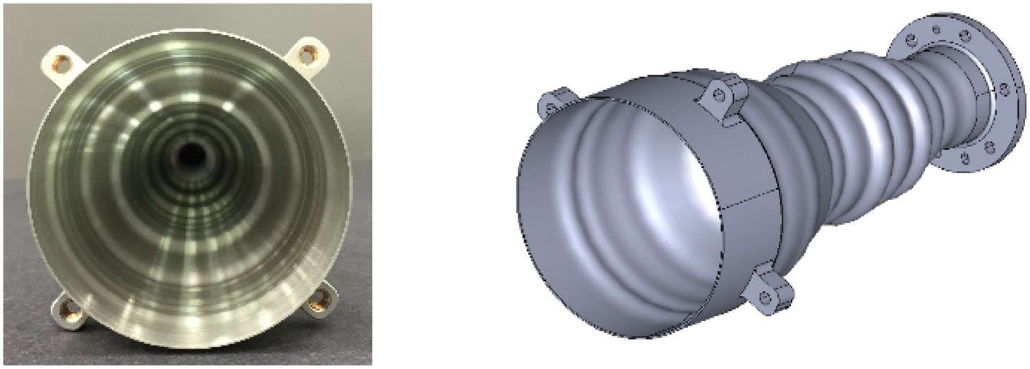
The mechanical layout of the spline horn is based on a thin-wall design, properly optimized in order to minimize mass and survive vibrations and thermo-elastic loads. Given the element spacing on the array, the wall thickness has been minimized to provide the maximum allowable radiating aperture. The wall thickness close to the horn aperture is only 0.5 mm and <1.6 mm all long the full profile (Fig. 6).
Spline-profile thin-wall horn aperture (left) and physical layout (right). ([Reference Pascale, Maiarelli, D'Agristina and Gatti10]; copyright EurAAP; used with permission)

High-pass dual-polarization filter (HPF)
The main purpose of the filters embedded in each radiating chain is to protect the low-noise Rx front-end stages from high level signals coming from the Tx antenna embarked in the same satellite. The filter shall provide very sharp rejection, due to <3% separation between Tx and Rx bands, as well as good matching and minimum group-delay variation within 14% fractional bandwidth centered about 13.9 GHz. As these functions shall be implemented for both the polarizations simultaneously, a single-filtering structure operating in dual polarization would allow minimizing the radiating chain envelope, mass, and overall complexity. The existing examples of dual-polarization HPFs are mainly based on cut-off, square, or circular, waveguide sections. These solutions are, however, quite limited in terms of achievable rejection and do not allow good control of group-delay variation and return loss characteristics in the pass-band. The overall length of the cut-off waveguide, necessary to achieve the required rejection, plus quarter wavelength sections for the required matching, would lead to unacceptable axial length, increased RF losses, and higher mass.
A solution based on iris-coupled TE11 circular resonators, implementing an all-poles Chebyshev filter, would provide better performance, but high filter orders are still necessary to achieve the required rejection slope, again leading to unacceptable lengths.
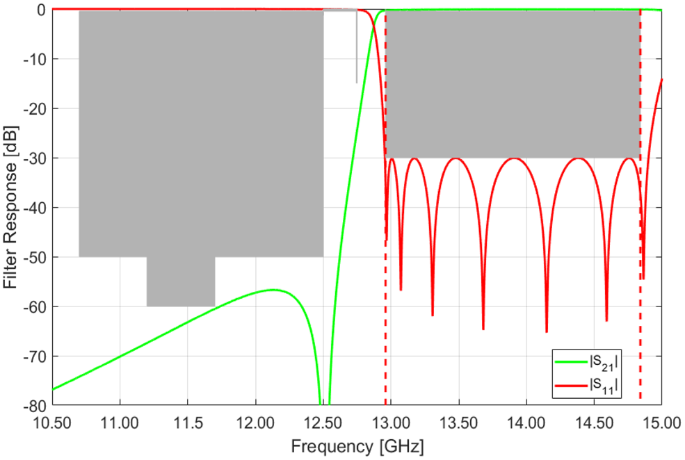
The minimum-filtering function fulfilling the specifications is a 7-2-0 generalized Chebyshev, requiring the implementation of two transmission zeros, which is not a trivial task in a dual polarization structure (Fig. 7).
Theoretical filter performance: [7-2-0] generalized Chebyshev (double transmission zero at 12.5 GHz).

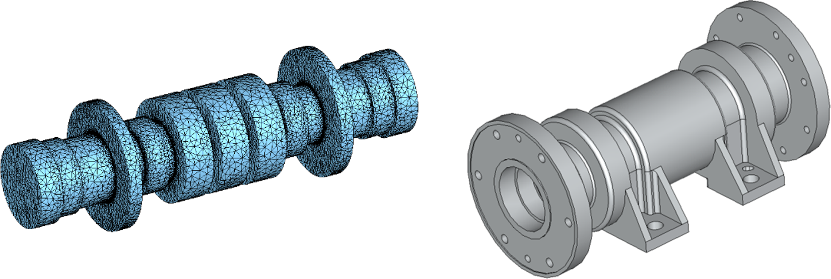
The design solution proposed, shown in Fig. 8, can overcome all the aforementioned limitations. The structure allows us to implement a pair of transmission zeros with an in-line configuration, fully suitable to dual-polarization operation, offering significant improvements in terms of RF performances, size and manufacturing costs, over the existing cut-off waveguide or TE11 realizations.
Dual polarization high-pass filter – FEM EM model (left) and physical layout (right). ([Reference Pascale, Maiarelli, D'Agristina and Gatti10]; copyright EurAAP; used with permission)

The filter is realized by a cascade of radial stubs in circular waveguide, implementing TM110 resonators separated by circular irises. The working principle is described in [Reference Bornemann and Yu12]: each radial stub acts as a TM110 mode resonator, whose magnetic field lines remain constant over the length of the resonator and couple with those of the non-resonant TE11 fundamental mode. Such interaction generates a negative bypass coupling which creates a transmission zero below the resonance frequency and an associated reflection zero. The rotational symmetry guarantees identical dual polarization operation as well as excellent polarization isolation (theoretically infinite). Radial stubs resonating at TM110 show several advantages over the more common TE11 resonators [Reference Rosenberg, Amari and Bornemann13]. In particular, the resonance frequency of the lowest order TM110 does not depend on cavity length, this feature allows us to keep the overall filter length at minimum.
In addition, the resonators can easily generate transmission zeroes below the resonance. This choice minimizes the overall complexity and provides a reliable solution for a quasi-high-pass filter implementation, with sharp rejection characteristics. Furthermore, it brings practically no additional constrains for the radiating element integration in the array, due to its compact dimensions. The non-resonant characteristics of the fundamental mode propagating through the structure, allow us to keep low RF losses also in a standard aluminum implementation, without recurring to silver plating.
The filter has been dimensioned to perform the required out-of-band rejection, together with good matching and minimum insertion loss over the full operating bandwidth, including a suitable margin for temperature drifts. The initial coupled-resonators filter synthesis has been performed with an in-house tool, followed by a preliminary dimensioning of circular waveguide resonators and coupling irises, performed using the analytical approach described in [Reference Amari and Bornemann14]. Optimization of the component electromagnetic model has been carried out using commercial mode-matching tools. Final verification and design analyses have been performed with FEM simulations in CST Microwave Studio (https://www.3ds.com).
Specific constraints have been imposed on the diameters of the irises and radial stub resonators, to allow filter manufacturing in a single block, by standard CNC turning.
Compact OMT with coaxial I/Fs
The proposed OMT design is based on a standard taper/branching waveguide configuration [Reference Uher, Bornemann and Rosenberg15]. The general layout is composed of a T-junction with two orthogonally oriented arms in rectangular waveguide, supporting single TE10 modes (Fig. 9).
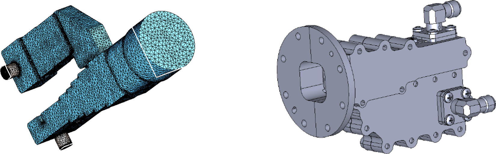
OMT with an integrated coaxial SMA O/P port – FEM model (left) and physical layout (right). ([Reference Pascale, Maiarelli, D'Agristina and Gatti10]; copyright EurAAP; used with permission)

The third arm, in square waveguide, supports the two orthogonal polarization modes TE10 and TE01. The taper between the square and the rectangular in-line arm, is stepped to achieve a good matching of the transition within the required bandwidth. The branched arm is coupled to the square waveguide through a slot iris, which provides also the required matching. A mitered H-plane bend is then implemented in order to align the branched arm with the main axis of the radiating chain. High port-to-port isolation and polarization purity are achieved, thanks to the symmetry of the structure and the orthogonality of fields' distribution. A rounded-edges square section is implemented at the common port, to match the transition to circular waveguide. The overall structure is properly dimensioned to keep residual levels of higher order TE11 and TM11 modes (that could affect cross-polar performance) practically negligible at the square common port.
The O/P port of each polarization is provided in coaxial SMA right angle (elbow type) connectors, allowing for an easy and versatile interface with the antenna RF electronics. Waveguide to coaxial transitions are directly embedded in the OMT design, realized with a single coaxial probe, in avoidance of soldering joints or sliding contacts. The probe protrudes from the SMA flange mount connector inside the waveguide and it is provided of capacitive loading to improve matching, obtained with the same dielectric material used as a connector isolator. A single-tuning screw is included in the transition design, allowing for the compensation of connector tolerances and fine tuning of the phase alignment between manufactured feed chains.
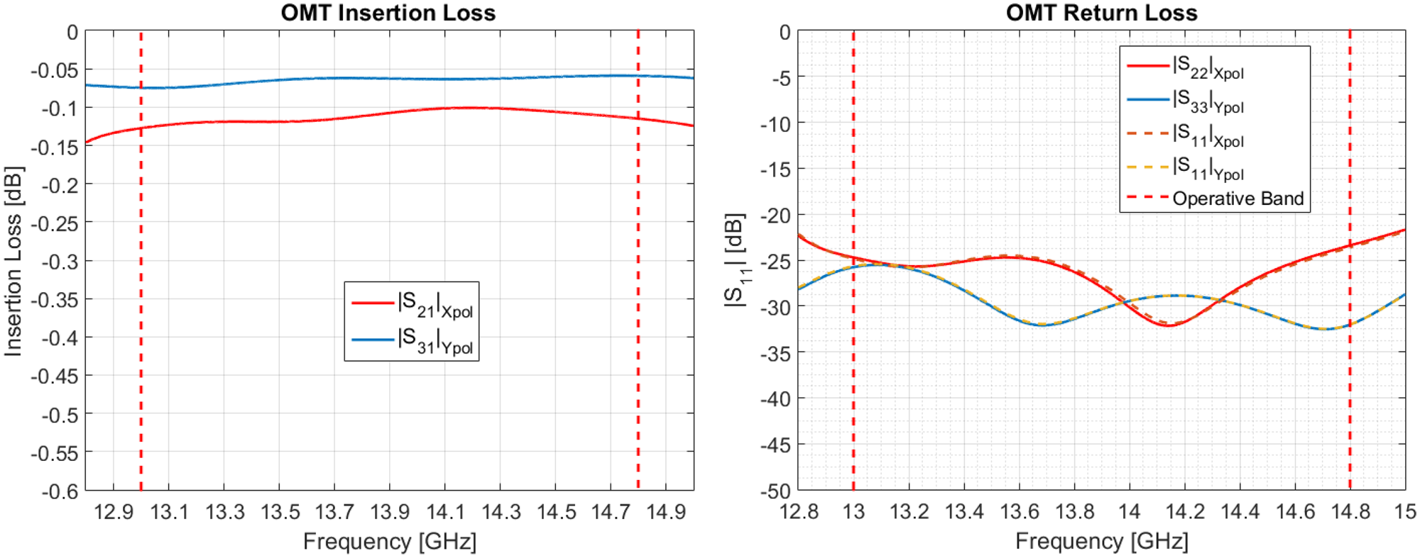
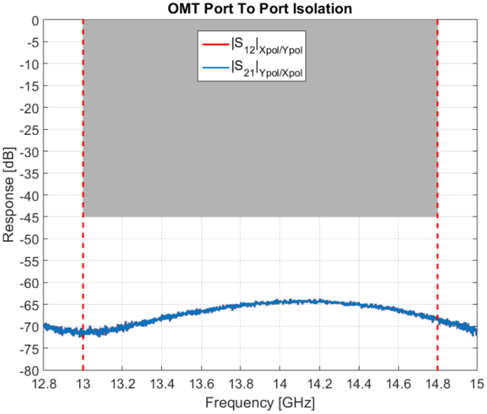
The OMT design has been entirely carried out using the full wave (FEM) simulation with CST Microwave Studio (Figs 10 and 11).
Simulated OMT insertion loss (left) and return loss (right) for both polarizations.

Measured OMT port-to-port isolation.

Rounded edges are implemented in the internal OMT geometry, to allow easy manufacturing in clamshell by direct CNC milling with high dimensional accuracy. A particular arrangement of the housing in two halves allows minimizing misalignments during the integration.
Radiating chain overall RF design
Radiating chain overall performances have been calculated and optimized at full chain level using the generalized scattering matrix method, by connecting the building blocks through multi-mode ports. Margins for thermal bandwidth have been included in the design, considering aluminum implementation. For final performance assessment, the full chain has been full-wave simulated over the operating temperature range, by varying the geometry in accordance with the thermal expansion of materials (CTE) and by adjusting materials conductivity based on temperature resistivity coefficient. Monte-Carlo analyses have been performed to determine the maximum allowable manufacturing tolerances, to avoid unnecessary complexity in the manufacturing process. Components design has been engineered for manufacturing with standard precision CNC milling or turning, avoiding spark-erosion machining, to achieve high accuracy, tight tolerances, and minimum surface roughness.
Thermo-mechanical design
The Rx feed chain structural design has been dimensioned to withstand the environmental loads seen both during satellite launch and in-orbit operating phases. A detailed FEM model of the feed chain assembly has been generated starting from the CAD solid model and used for the static and dynamic analyses. The MSC Nastran software tool has been employed for the analyses and MSC Patran and Altair Hyperworks for pre/post processing of results. In addition, the thermo-elastic behavior of the structure has been simulated using the FEM model and material properties.
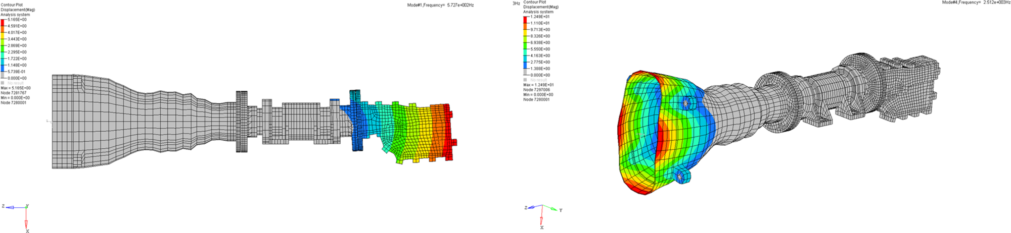
Eigen-frequencies and mode shapes of the feed have been calculated with a modal analysis; an example of outputs is shown in Fig. 12. The first two modes (560 and 600 Hz) are bending modes involving mainly the OMT, the fourth mode (2515 Hz) is a local mode of the horn.
Modal analysis – mode-shapes (deformation) of first and fourth mode.

Margins of safety of the structure have been calculated under specified random and sinusoidal vibrations loads, resulting positive in all the cases. Bolted joints verification has been also performed giving no evidence of critical aspects with the selected fasteners.
A shock analysis has been performed using MSC Nastran SOL103, based on the structural response calculated for the response spectrum input in normal modes analysis. The resultant structural margins confirmed that the feed chain assembly is not sensitive to mechanical shock.
Feed chain qualification and test results
An engineering qualification model (EQM) of the radiating element has been manufactured and subject to space qualification campaign. The following production run has comprised in excess of 90 flight units, which have been acceptance tested and delivered for the integration at the antenna level.
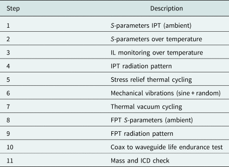
Table 2 provides a summary of the qualification test campaign performed.
Qualification test sequence

After each environmental test, an RF check (S-parameters) has been performed.
In the following paragraphs, a summary of the main qualification test results is reported.
S-parameters performances
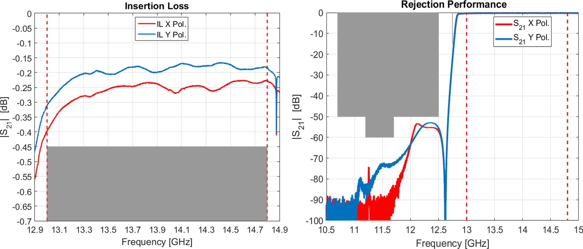
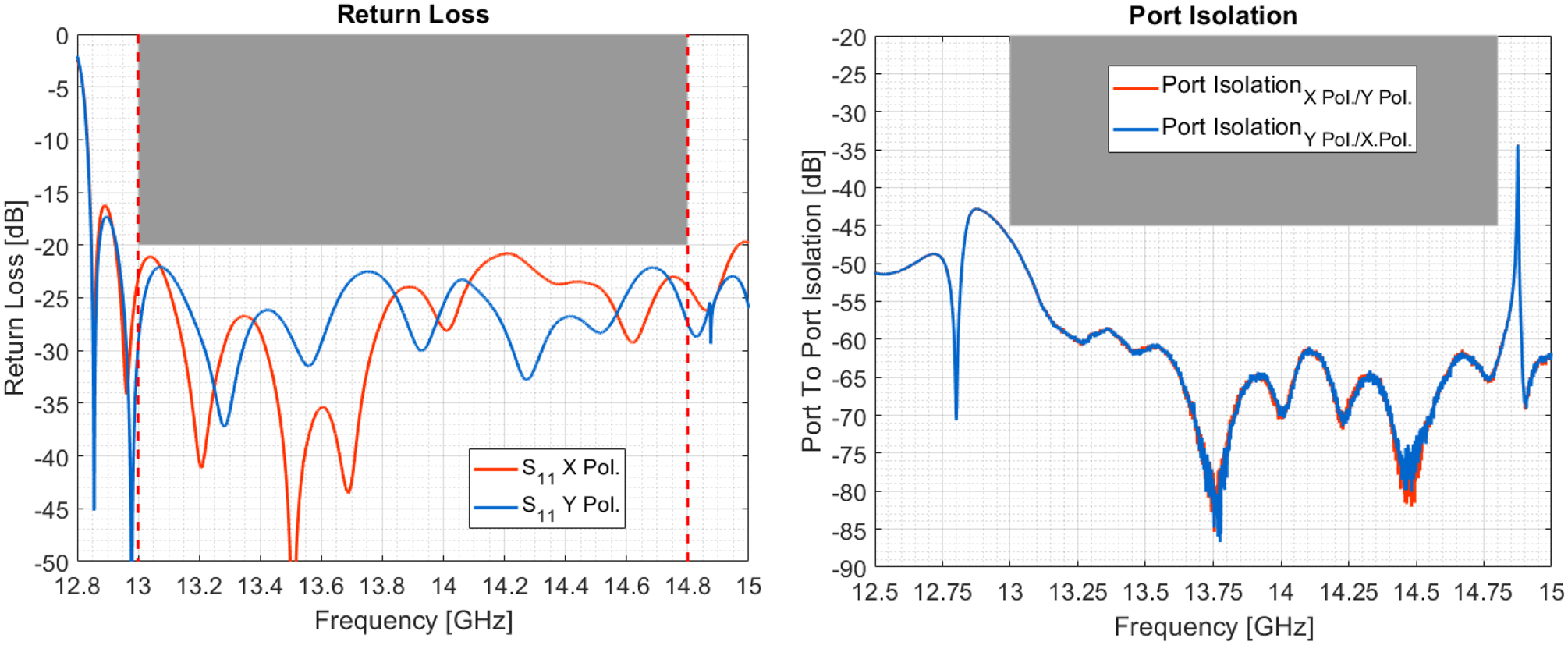
S-parameters measured under ambient conditions are reported in Figs 13 and 14.
Measured feed chain insertion loss (left) and out-of-band rejection (right) for both polarizations. ([Reference Pascale, Maiarelli, D'Agristina and Gatti10]; copyright EurAAP; used with permission)

Measured feed chain return loss (left) and port-to-port isolation (right) at coaxial SMA O/P ports for both polarizations. ([Reference Pascale, Maiarelli, D'Agristina and Gatti10]; copyright EurAAP; used with permission)

Insertion loss and rejection have been measured at the interface between filter (HPF) and horn, using a conducted S-parameters test set-up. The insertion loss of the horn has been verified stand-alone in the reflection mode and its contribution added to the overall budget. The measured losses also include the contribution of right-angle SMA connectors.
The rejection is always better than 50 dB over the full satellite downlink (Tx) bandwidth [10.7–12.5 GHz]. Group-delay variation in every 250 MHz in the operative bandwidth is always lower than 0.8 ns peak-to-peak.
The return loss at SMA I/Fs is always better than 21 dB and the measured port-to-port isolation is better than 45 dB. Note the single spike appearing at 14.87 GHz, which is due to the TM01 mode in circular waveguide between the OMT transition and the first iris of the HPF. The geometry has been optimized at the assembly level in order to keep this spike outside the operating band even including thermal allowance.
S-parameters test over temperature
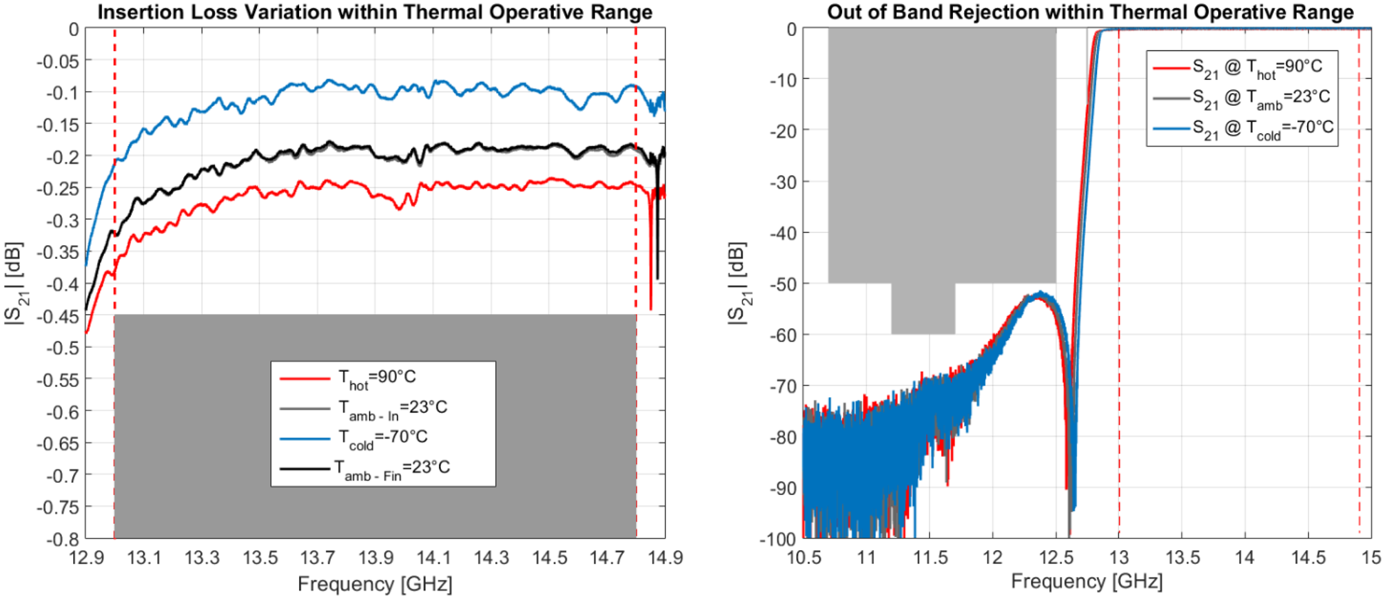
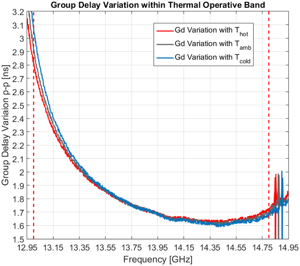
The RF performances have been measured over the operating temperature range on both the EQM and FM units. Figs 15 and 16 show the insertion loss, out-of-band rejection and group delay variation at different temperature plateaus. The measured frequency drift over temperature and the insertion loss (IL) variation with temperature is exactly in line with the predictions performed by full-wave simulations.
Y-Polarization. Measured rejection (left) and insertion loss (right) over the qualification temperature range. ([Reference Pascale, Maiarelli, D'Agristina and Gatti10]; copyright EurAAP; used with permission)

Y-Polarization. Measured group-delay variation over the qualification temperature range.

The insertion loss of the device under test has also been continuously monitored during hot–cold temperature transitions, showing no glitches or abrupt changes due to thermo-elastic distortions.
Environmental tests
Full mechanical vibration tests (sine and random), along the three axes, have been performed on the EQM. Random vibration profiles applied for qualification, reached accelerations higher than 40grms, exceeding typical satellite busses requirements. Resonance search and visual inspections have been performed before and after each vibration run, along each axis, in order to identify any possible changes or damages. To confirm the successfulness of the mechanical qualifications, RF performances (S-parameters) measured before and after mechanical testing, have been compared, showing no changes in functional behavior.
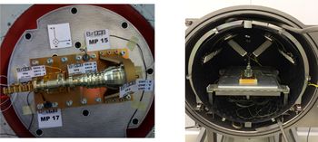
The feed chains have been designed to withstand the thermal stress induced by the antenna structure in a geostationary orbit. In order to verify the design, a thermal cycling in vacuum environment (TVAC) has been performed; the TVAC chamber set-up is shown in Fig. 17. The worst case temperatures for qualification were set to [−85 to +95°C]. The feed chains passed the thermal cycling test without damages. The S-parameters measured before and after the test show an excellent agreement.
Mechanical vibration test set-up (left) and thermal vacuum test set-up (right) used for qualification tests.

Cross-polar frequency sweep measurements
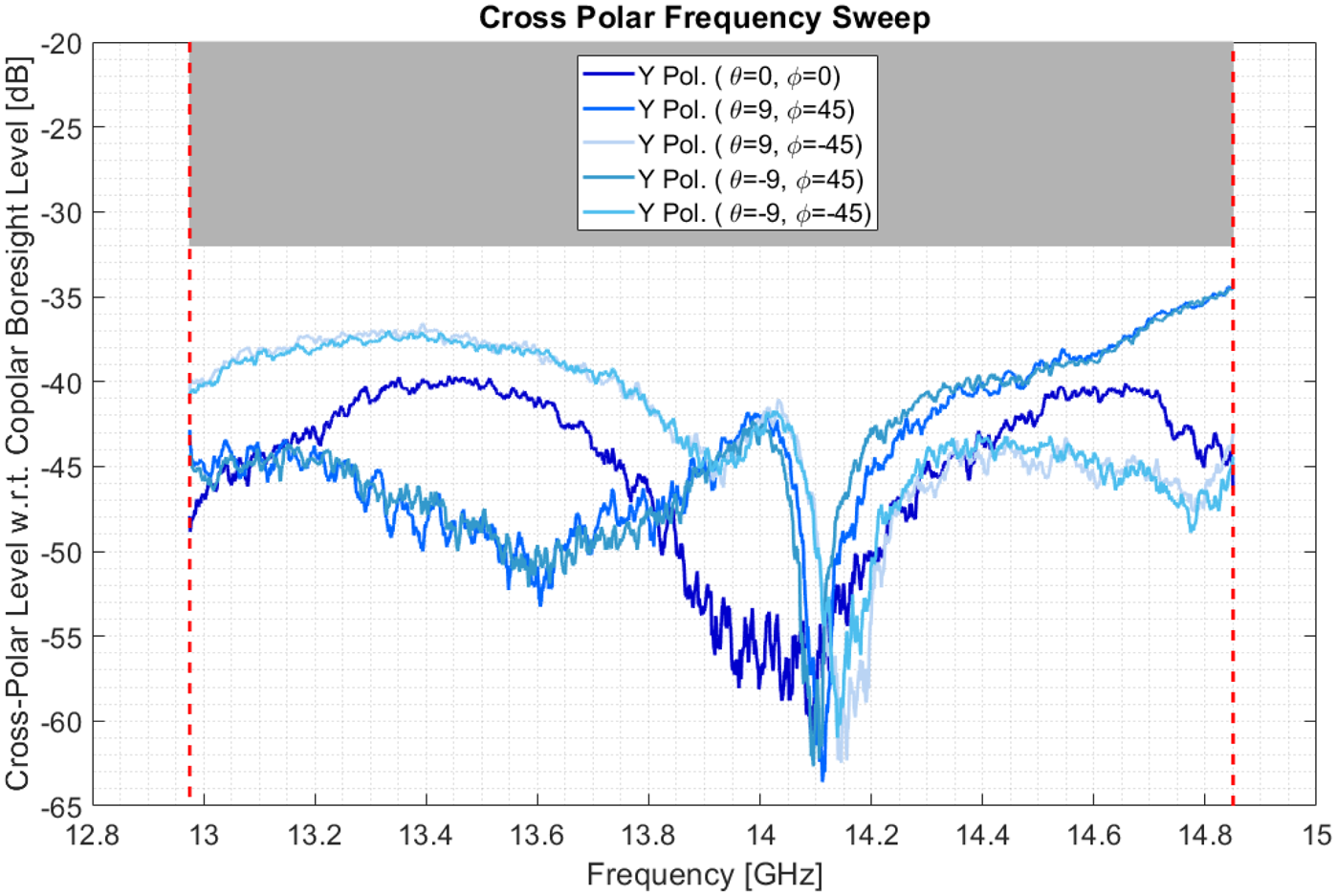
High polarization purity is a key requirement for the feed chains. A suitable design of the polarization device (OMT) allows us to theoretically achieve the required performances, but the OMT geometry must also be robust with respect to manufacturing tolerances and shall guarantee a precise assembly and integration process. Higher order modes can be triggered by asymmetries between the OMT shells, or junctions, due to manufacturing or integration mishandling, and can generate undesired cross-polar levels, or sharp resonances (spikes) if they remain trapped within the structure. In order to check the accuracy of the integration processes, a cross-polar sweep measurement, over the full frequency range, has been performed in the antenna test range. A typical plot of measured cross-polar level versus frequency is shown in Fig. 18.
Radiating chain cross-polar frequency sweep measurement.

Radiation pattern measurements
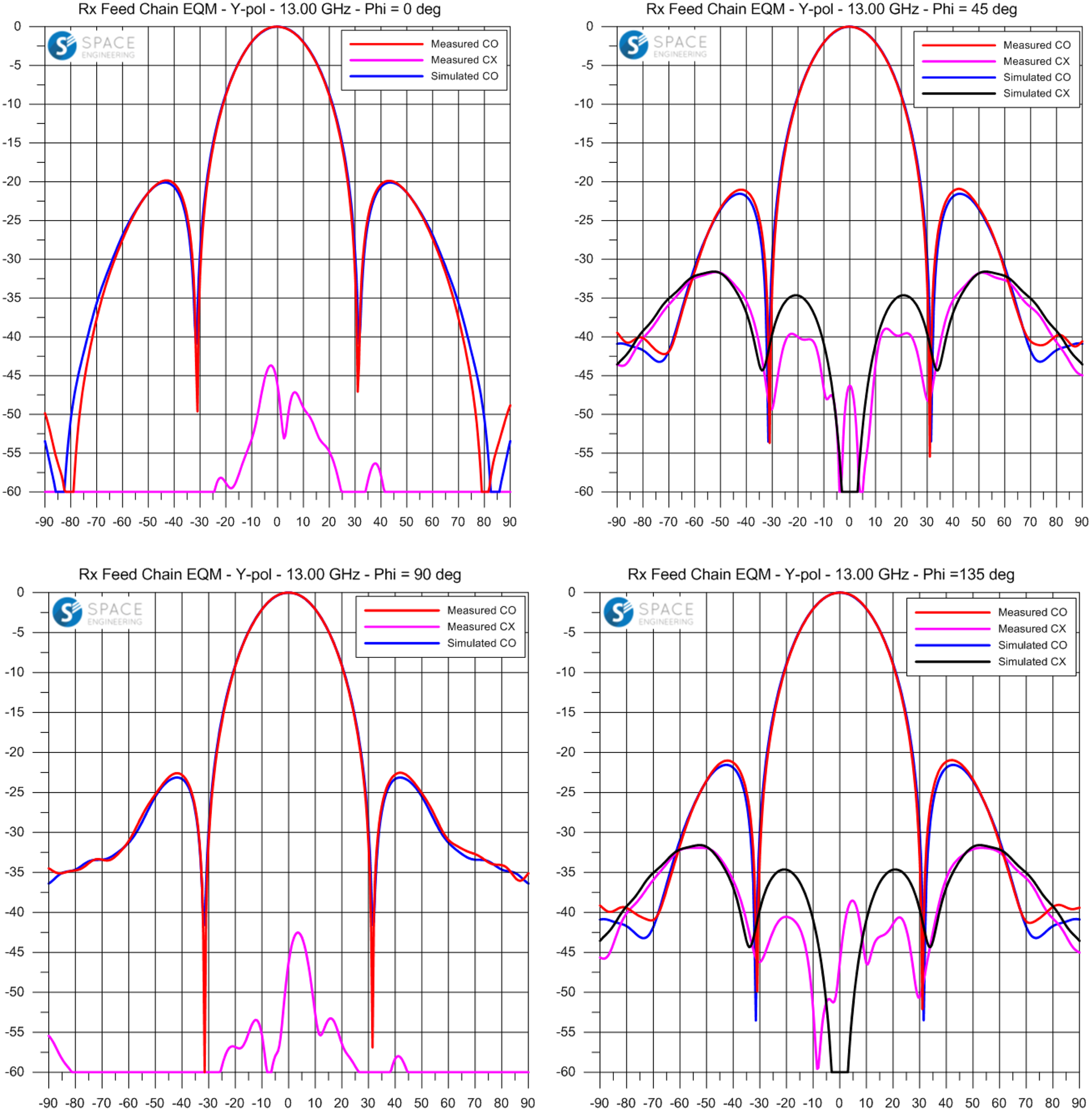
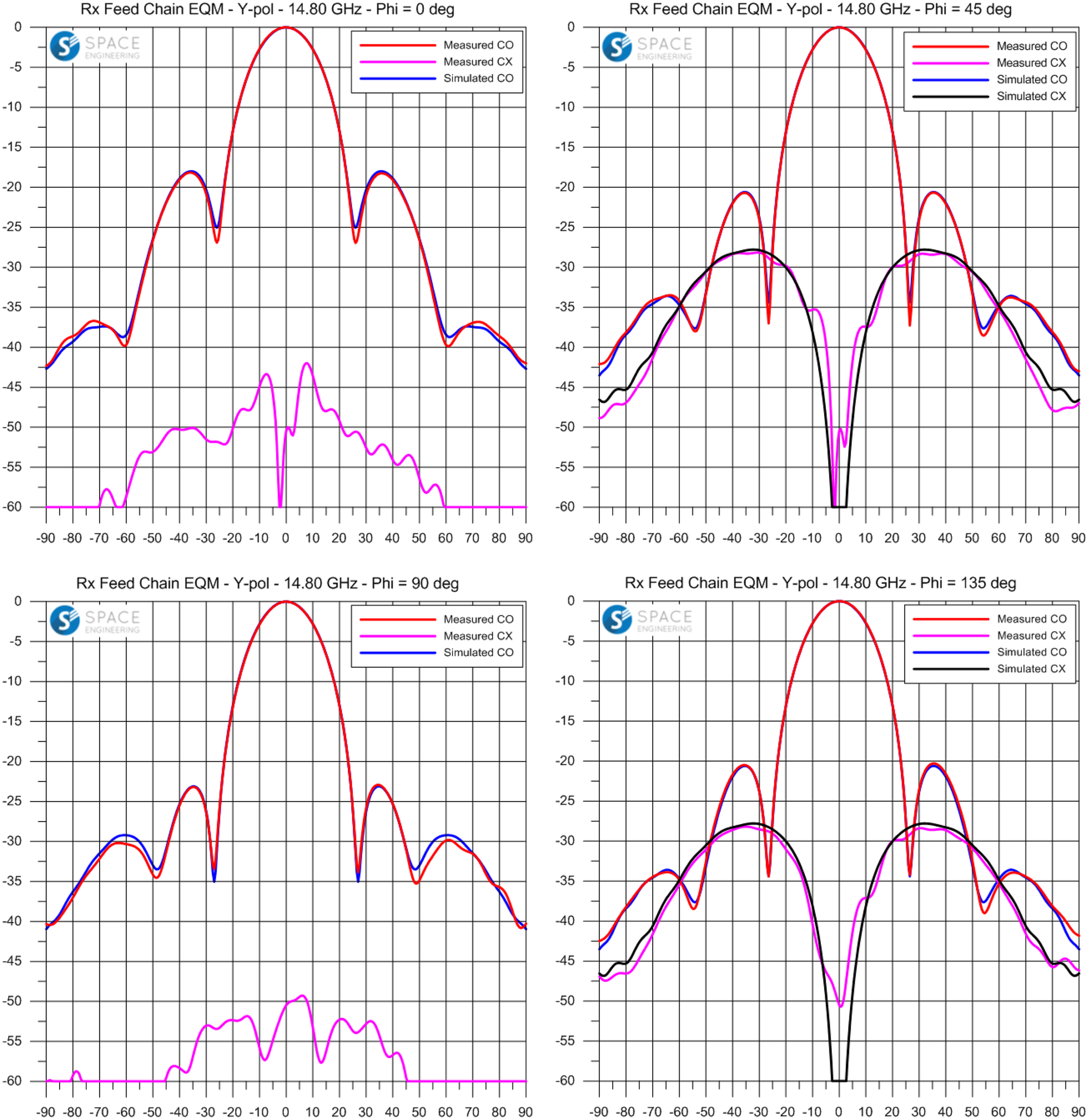
Radiation pattern measurements have been performed at the beginning and at the end of the environmental qualifications. Measured pattern cuts for Y-polarization, including comparison with simulated performances, at the extreme frequencies of the operative bandwidth, are reported in Figs 19 and 20 (X-polarization results are similar). An excellent agreement can be noticed between the measured and expected patterns, for both the co-polar and cross-polar components.
Measured pattern cuts versus simulated – Y-polarization – 13.00 GHz. ([Reference Pascale, Maiarelli, D'Agristina and Gatti10]; copyright EurAAP; used with permission)

Measured pattern cuts versus simulated – Y-polarization – 14.80 GHz. ([Reference Pascale, Maiarelli, D'Agristina and Gatti10]; copyright EurAAP; used with permission)

Radiated performances in embedded configuration
To evaluate the radiated performances in the final DRA antenna, the feed chains have also been simulated and measured in the embedded configuration. A correlation has been carried out comparing a set of range tests performed on the Rx feeds arranged in different 3 × 3 sub-array configurations.
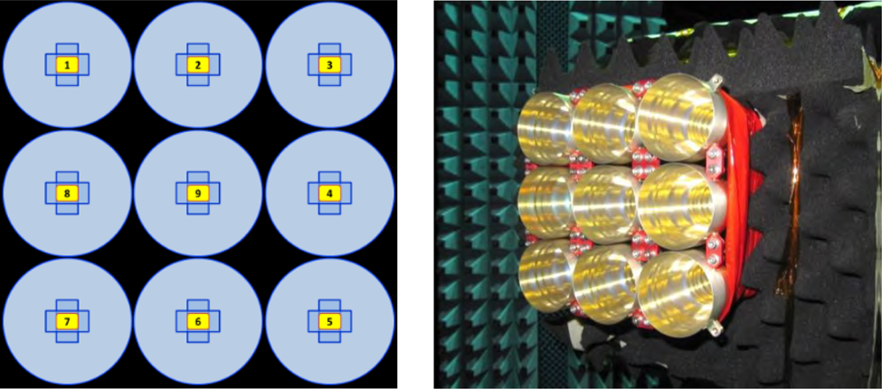
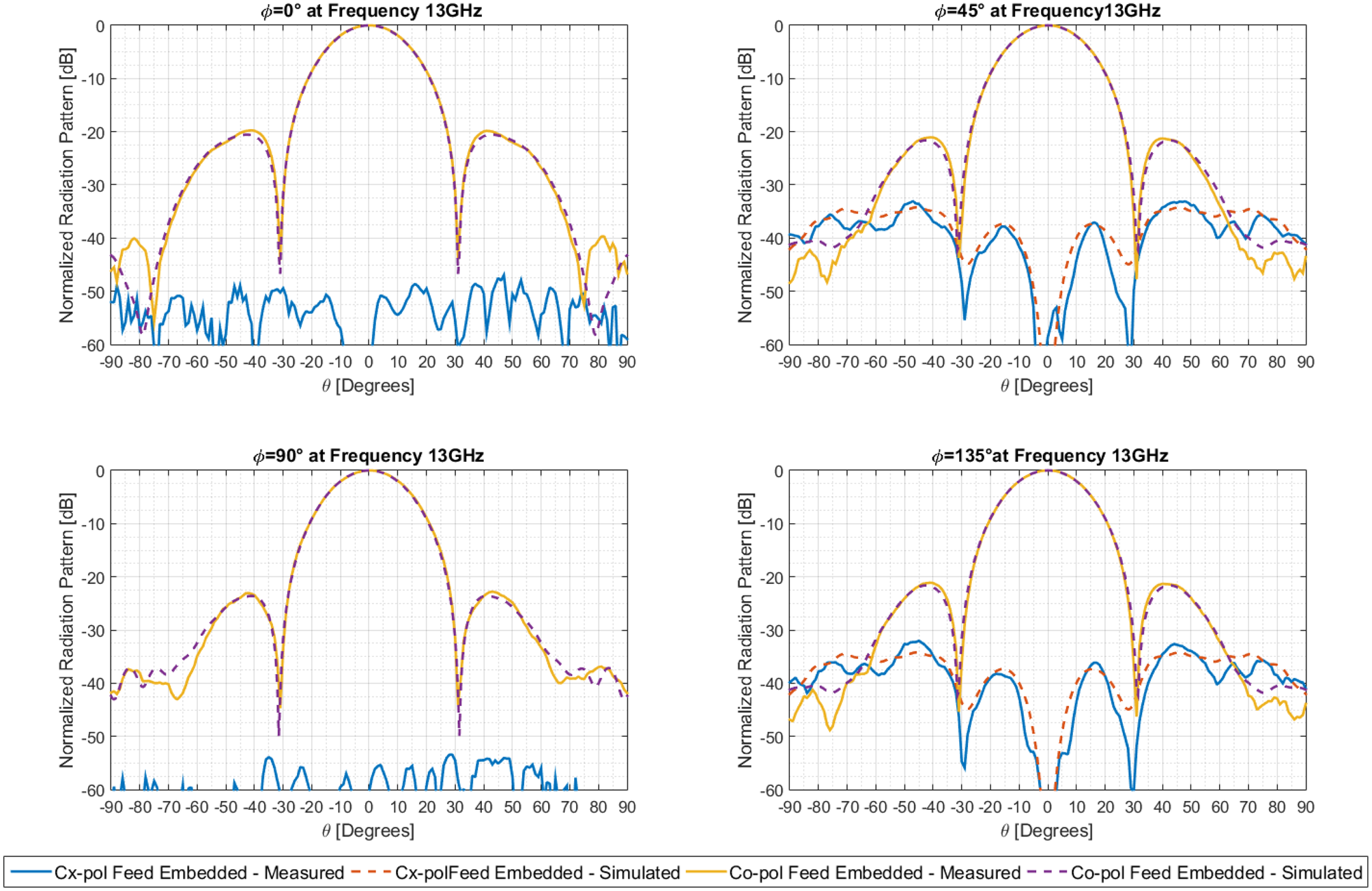
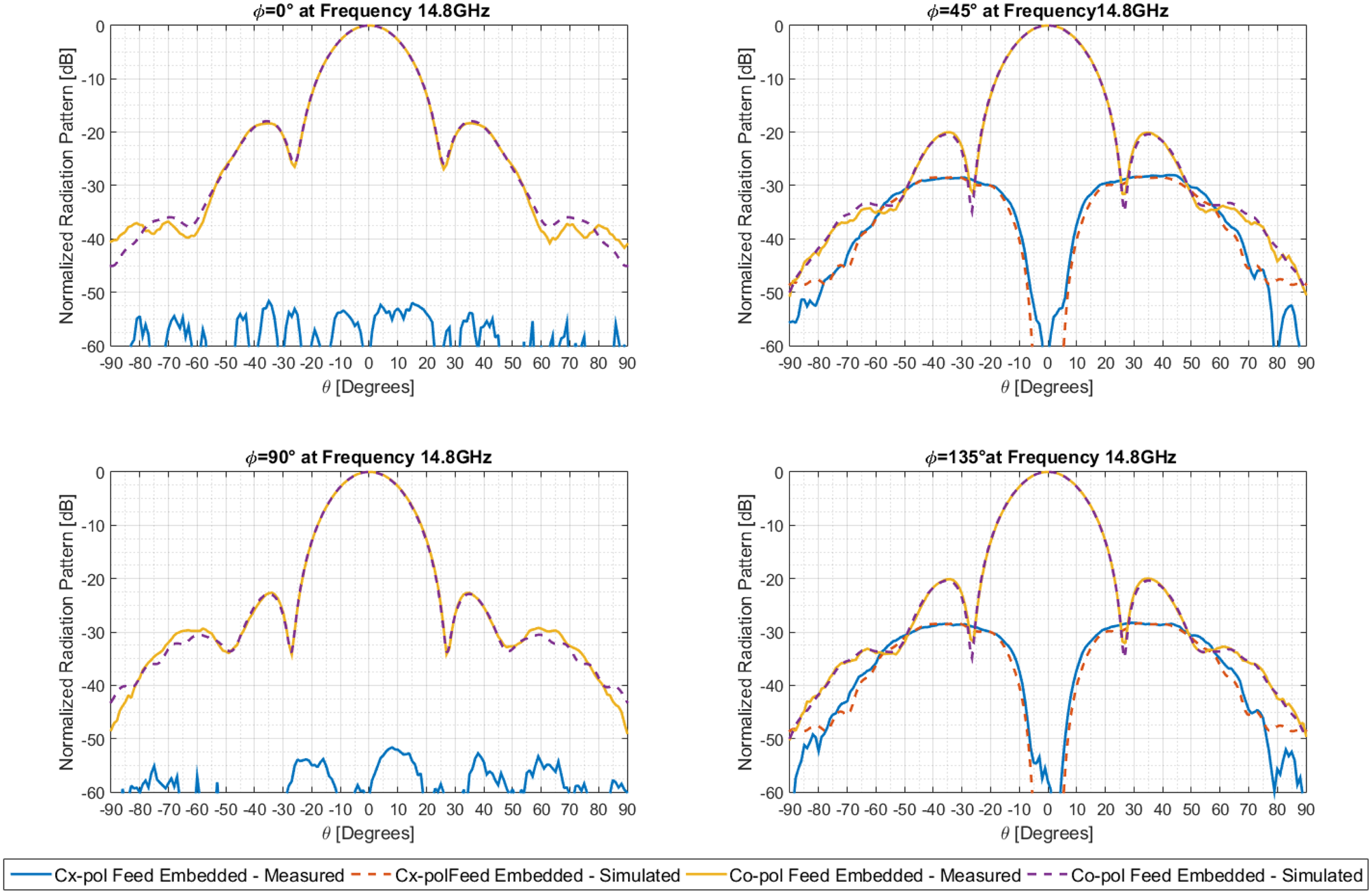
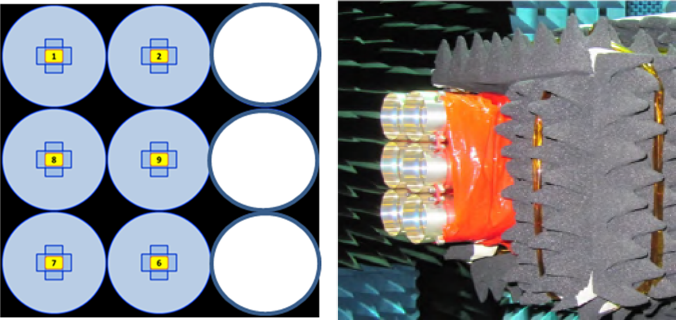
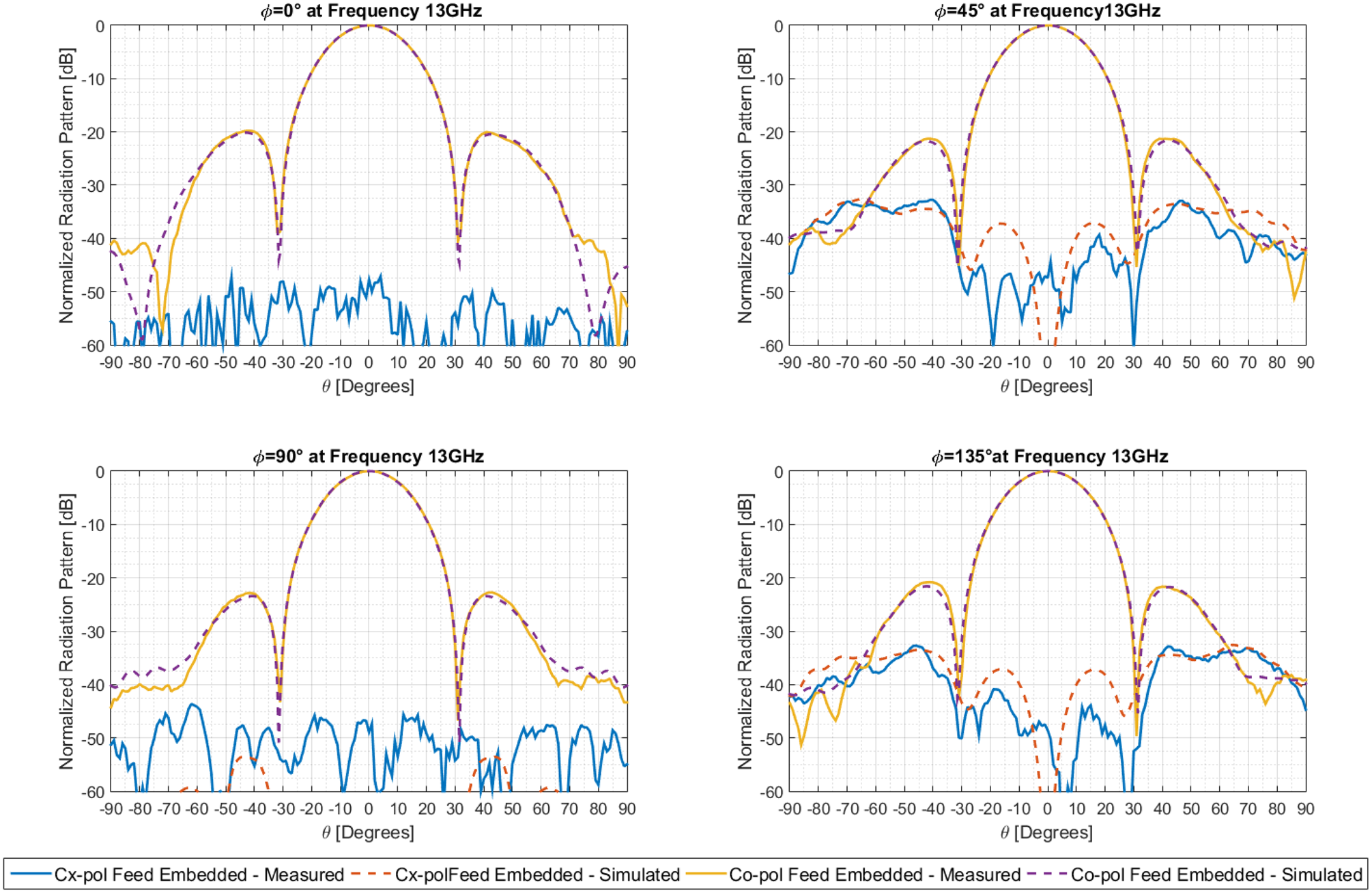
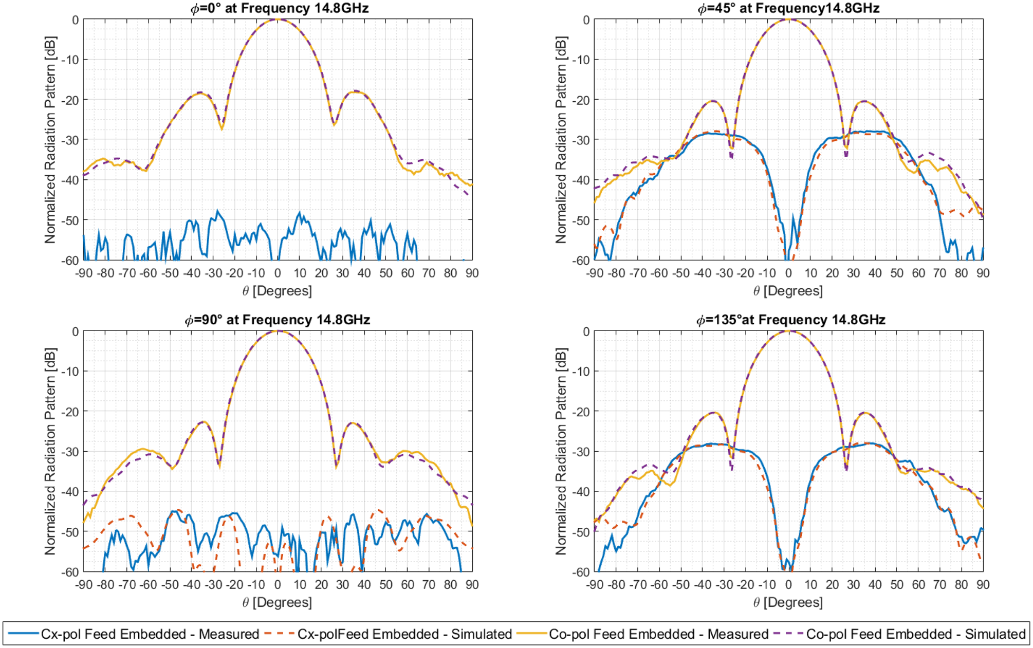
The tests have been performed for both EDGE and EMBEDDED element configurations, in order to cover all the possible cases occurring in the array. The EMBEDDED configuration reproduces the feed boundary conditions as part of the DRA square lattice. The center element is fed while the surrounding eight are closed on a matched load. Radiation pattern tests in the EMBEDDED configuration have been performed at Airbus-DS UK facilities (Figs 21–23).
Embedded element configuration (Courtesy of Airbus-DS UK).

Measured pattern versus simulated – embedded element Y-polarization – 13.00 GHz.

Measured pattern versus simulated – embedded element Y-polarization – 14.80 GHz. ([Reference Pascale, Maiarelli, D'Agristina and Gatti10]; copyright EurAAP; used with permission)

The EDGE configuration reproduces the boundary conditions of the feed placed at the edge of the DRA lattice. The center element is fed while the surrounding five are closed on a matched load (Figs 24–26).
Edge element configuration (Courtesy of Airbus-DS UK).

Measured pattern versus simulated – edge element Y-polarization – 13.00 GHz.

Measured pattern versus simulated – edge element Y-polarization – 14.80 GHz.

An excellent agreement has been found between the measured and predicted patterns for both the co-polar and cross-polar and for both the X and Y polarizations. Minor differences found between the measured and predicted patterns are within the limits of the typical accuracy achievable in antenna range measurements at Ku-band frequencies.
As expected, the larger differences are found for |θ| > 40°, due to the lower S/N ratio (lower strength of the measured field) and possible interactions with the supporting structure (Mechanical Ground Support Equipment).
The mutual coupling between the adjacent horns has also been measured and compared with simulations, showing very good agreement between the measured and predicted results.
Performance similarity among manufactured units
More than 90 flight units have been manufactured, acceptance tested, and delivered to Airbus-DS for the integration on the quantum payload. Fig. 27 shows 21 units from the first production lot.
Twenty-one radiating elements units of the first production lot (FM batch #1). ([Reference Pascale, Maiarelli, D'Agristina and Gatti10]; copyright EurAAP; used with permission)

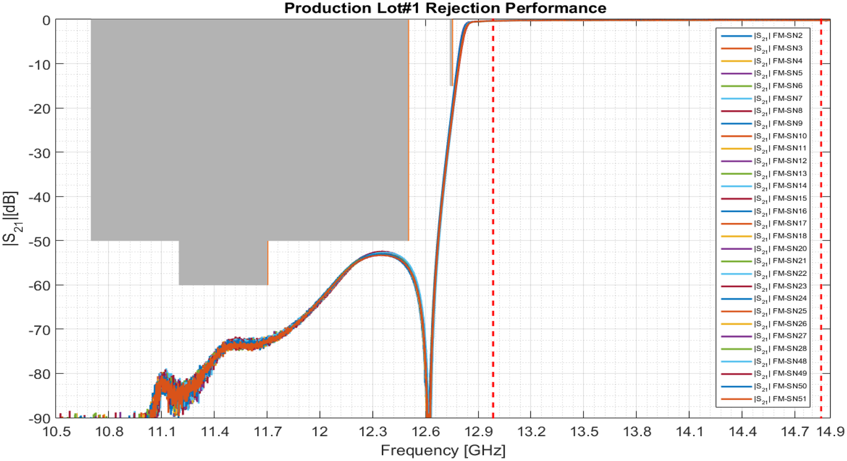
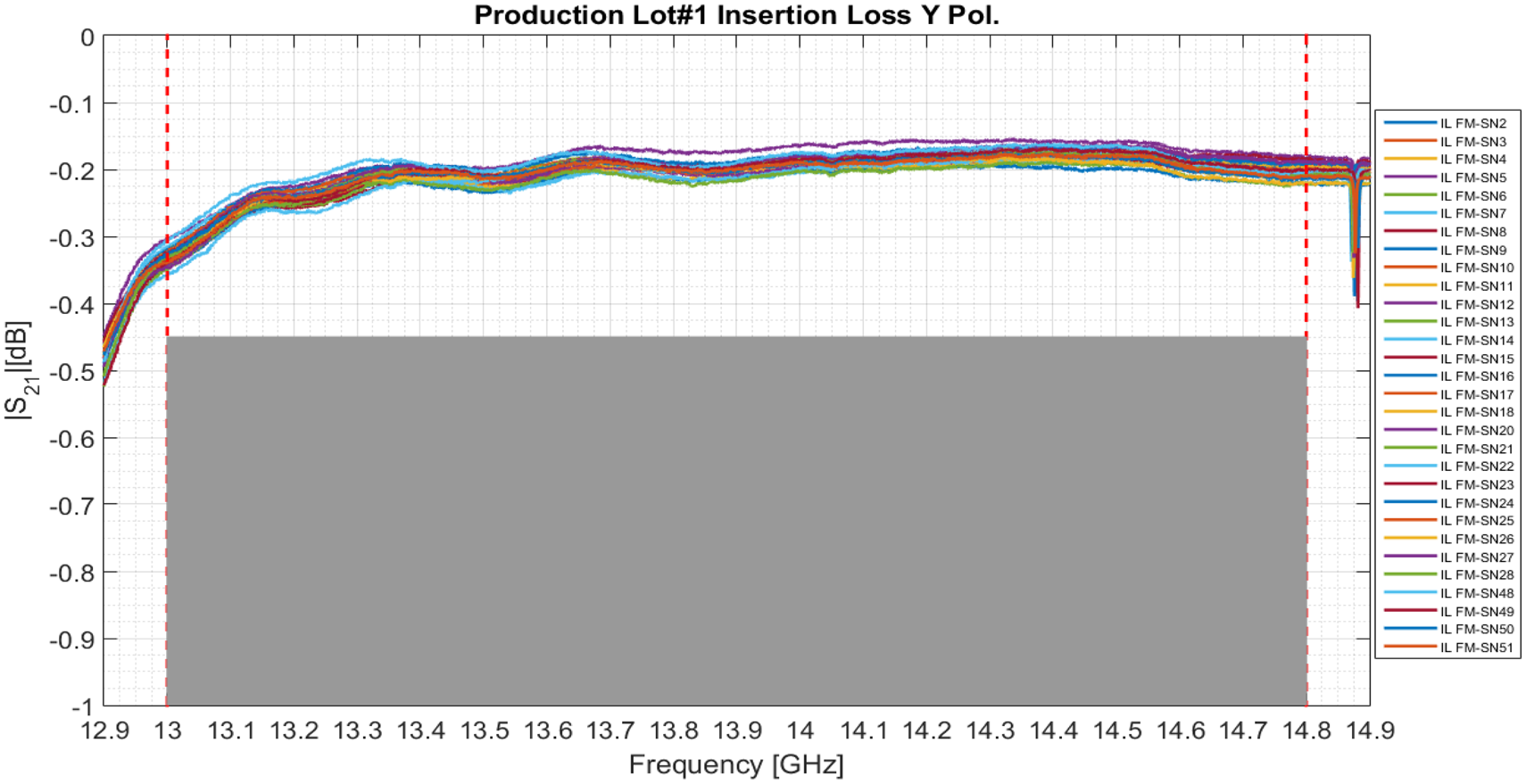
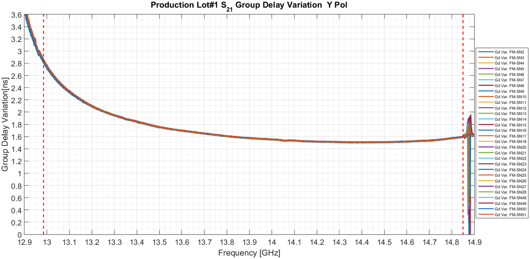
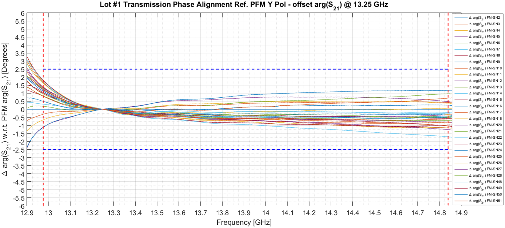
The results of some acceptance tests, as performed on the flight units of the first production batch, are reported in Figs 28 to 31.
FM batch #1 – measured rejection SN (02-28/48-51). ([Reference Pascale, Maiarelli, D'Agristina and Gatti10]; copyright EurAAP; used with permission)

Insertion loss and rejection characteristics of the different units are impressively overlapping (Figs 28 and 29).
FM batch #1 – measured IL performance, Y-polarization SN (02-28/48-51). ([Reference Pascale, Maiarelli, D'Agristina and Gatti10]; copyright EurAAP; used with permission)

In addition, the group-delay variation and transmission phase (Figs 30 and 31) show an excellent similarity among the units, confirming the robustness of the design and the accuracy of the manufacturing. The absolute phase difference among units is comprised within ±2.5° within the full pass band.
FM batch #1 – measured group-delay, Y-polarization SN (02-28/48-51).

FM batch #1 – measured phase tracking Y-polarization SN (02-28/ 48-51) – Ref. PFM SN02. ([Reference Pascale, Maiarelli, D'Agristina and Gatti10]; copyright EurAAP; used with permission)

The tests performed on all the flight units confirmed the excellent similarity among the full production run, including radiated performances.
Conclusion
The design and qualification of a compact and modular dual polarization radiating chain, developed for the Ku-band Rx antenna of Eutelsat Quantum satellite and suitable for use on several active DRA antennas and satellite payload applications has been presented. The equipment shows excellent characteristics in terms of efficiency, directivity, and polarization purity. Very low insertion loss, group-delay variation, and high performance repeatability, make the feed especially suitable for use in large wideband arrays. The radiating chains integrate also dual-polarization filters, providing sharp out-of-band rejection in the downlink Ku-band. The design is particularly optimized for small envelope, low mass and relatively high-volume productions. The equipment has been qualified for severe space environment conditions and more than 90 flight units have been already manufactured and delivered by Airbus Italia S.p.A. Measured performances are in very good agreement with the predictions and show an excellent repeatability among the full production run.
 Vincenzo Pascale received Laura degree in Telecommunication Engineering with specialization in Electromagnetic Technologies and Ph.D. in Electromagnetics from the University of Rome, “ La Sapienza,” Italy in 2010 and 2016, respectively. From 2010 to 2014 he worked as an RF and Antenna Engineer at Thales Alenia Space-Italia. He was involved with institutional and research projects supporting antenna design and testing for satellite avionic terminals and dimensioning coverages for several institutional and commercial satellite missions. He also participated, as an Antenna Engineer, in research activities concerning satellite antenna systems for interference mitigation, in collaboration with Eutelsat, Telespazio, and ESA. In 2014, he joined Airbus Italia S.p.A., formerly Space Engineering S.p.A., as an RF Engineer in the Antenna and RF Passive components group, working as RF designer for RF passive satellite components, feed chains, and filters for several Telecommunication and Earth Observations Satellite Programs.
 Davide Maiarelli received the Laura degree (cum laude) in Electronic Engineering from the University of Perugia, Italy in 2001. From 2001 to 2015 he has been with Thales Alenia Space-Italy (formerly Alenia Spazio S.p.A.), Rome, as a Senior Antenna and RF engineer, Antenna System Engineer, and Project Manager. He worked on a number of commercial, institutional, and research projects designing and developing satellite antenna systems and microwave passive components. He participated in several research activities concerning modeling techniques for microwave/antenna components and numerical EM methods, in collaboration with Italian universities. In 2015, he joined Space Engineering S.p.A. (now Airbus Italia S.p.A.), Rome, as a Senior RF Engineer in the RF Passive components group, working as RF design, technical, and program manager for several satellite components, feed chains, and filters. Since 2017 he has been the Head of Antennas and RF Passive Engineering division of Airbus Italia S.p.A.
 Luciano D'Agristina is a Senior Antenna Engineer working in Airbus Italia, Rome, Italy. He received his master's degree in Electronic Engineering from the University of Catania in 2006 and the Master Course in “Satellites and Orbiting Platforms” from La Sapienza University, Rome, in 2007. He has been involved in various international projects related to space telecom applications such as Alphasat, SAOCOM, Metop MWI, and Quantum satellites. His expertise includes the detailed design of many types of antennas (GNSS path antennas, reflector antennas, active arrays, DRA, array fed reflectors, and corrugated and spline horns), with several lines of experience in using RF commercial tools. His present activity includes also a good experience in system analysis of telecommunication satellite environment and in numerical modeling methods aimed at the analysis, design and optimization of satellite antennas and payload systems.
 Nicola Gatti is a Senior Antenna Engineer and Project Manager working in Airbus Italia, Rome, Italy. He received a degree in Electronic Engineering from the University of L'Aquila in 1997. He has been with Airbus Italia, previously Space Engineering, since 1999. He was involved as an antenna designer and project manager in many antenna activities developed in the frame of several European Satellite Programs and ESA Study projects, such as EuroSkyWay, Satelcom, Radarsat-2, Amos-2, Cosmo SkyMed, Alphasat, Eutelsat Quantum, and MetOp SG MWI. For the Eutelsat Quantum program he was the project manager for Airbus Italia and was responsible for Tx antenna RF engineering. He is at present the antenna architect for MetOp SG MWI. His present expertise includes project management and design and analysis of complex active array antennas, reflector antennas, and imaging antenna systems, with production of software instruments for RF performance optimization.