1. Introduction
It has been known for many years that tokamak performance, as measured by pressure and energy confinement time, improves substantially as the plasma cross-section becomes more elongated. There are, however, also well known limits on the maximum achievable elongation, which arise from the excitation of
 $n=0$
vertical instabilities. When designing the next generation reactor scale tokamak experiments (Najmabadi et al.
1997, 2006; Aymar, Barabaschi & Shimomura Reference Aymar, Barabaschi and Shimomura2002; Sorbom et al.
Reference Sorbom, Ball, Palmer, Mangiarotti, Sierchio, Bonoli, Kasten, Sutherland, Barnard and Haakonsen2015), where high performance is critical, it is thus important to be able to accurately predict the maximum achievable elongation
 ${\it\kappa}$
as a function of inverse aspect ratio
 ${\it\varepsilon}=a/R_{0}$
, where
 $a$
is the minor radius of the device, and
 $R_{0}$
is the major radius.
The inverse aspect ratio is a particularly important parameter since different reactor designs have substantially different values for this quantity. Specifically, standard and high field tokamak reactor designs have
 $1/{\it\varepsilon}\sim 3{-}4.5$
(Schissel et al.
Reference Schissel, DeBoo, Burrell, Ferron, Groebner, St. John, Stambaugh, Tubbing, Thomsen and Cordey1991; Hutchinson et al.
Reference Hutchinson, Boivin, Bombarda, Bonoli, Fairfax, Fiore, Goetz, Golovato, Granetz and Greenwald1994; Najmabadi et al.
1997, 2006; Aymar et al.
Reference Aymar, Barabaschi and Shimomura2002; Sorbom et al.
Reference Sorbom, Ball, Palmer, Mangiarotti, Sierchio, Bonoli, Kasten, Sutherland, Barnard and Haakonsen2015), while spherical tokamaks have smaller
 $1/{\it\varepsilon}\sim 1.5$
(Sabbagh et al.
Reference Sabbagh, Kaye, Menard, Paoletti, Bell, Bell, Bialek, Bitter, Fredrickson and Gates2001; Sykes et al.
Reference Sykes, Ahn, Akers, Arends, Carolan, Counsell, Fielding, Gryaznevich, Martin and Price2001). Since optimized plasma performance and corresponding minimized cost depend strongly on
 ${\it\kappa}$
, it is important to have an accurate determination of
 ${\it\kappa}={\it\kappa}({\it\varepsilon})$
and this is the goal of the present and accompanying paper.
The problem of determining
 ${\it\kappa}={\it\kappa}({\it\varepsilon})$
has received considerable attention in past studies but, as discussed below, there is still an important gap in our knowledge. To put the problem in perspective, we note that earlier studies generally fall into one of three main categories, each one providing valuable information, but not the whole story. These are summarized as follows.
The first class of studies involves the concept of ‘natural elongation’. Here, the tokamak is immersed in a deliberately simple external poloidal magnetic field, usually a pure vertical field. The plasma is expected to be stable against
 $n=0$
vertical instabilities since one vertical position is the same as any other. In these studies (Peng & Strickler Reference Peng and Strickler1986; Roberto & Galvão Reference Roberto and Galvão1992) the free boundary equilibrium surface is calculated (i.e. the elongation
 ${\it\kappa}$
and the triangularity
 ${\it\delta}$
are determined) for a range of
 ${\it\varepsilon}$
from which it is straightforward to extract the desired
 ${\it\kappa}={\it\kappa}({\it\varepsilon})$
. Excellent physical insight is provided by these calculations. Even so, the maximum predicted natural elongations are substantially smaller than those achieved in experiments. The reason is that experiments have feedback systems that can stabilize
 $n=0$
vertical instabilities, thereby allowing larger
 ${\it\kappa}$
’s than those predicted by marginally stable naturally elongated configurations.
The second class of studies involves the calculation of the critical normalized wall radius
 $b/a$
for an ideal perfectly conducting conformal wall required to stabilize a desired elongation; that is, the analysis basically determines
 $b/a=f({\it\varepsilon},{\it\kappa})$
. Here too, the studies (Wesson Reference Wesson1978) (and references therein) provide valuable insight. Specifically, the studies determine the maximum
 $b/a$
that might potentially be able to be stabilized by feedback. However, the analysis does not actually predict whether or not a practical feedback system can be constructed to provide stability. Equally important, from a practical point of view, the actual value of
 $b/a$
does not vary much from experiment to experiment.
The third class of studies consists of detailed, engineering level designs that predict the maximum elongation and which include many effects such as plasma profiles, real geometry, safety margins and most importantly, the engineering properties of the feedback system. Such studies (Kessel et al.
Reference Kessel, Mau, Jardin and Najmabadi2006) are very realistic and are exactly what is required to design an actual experiment. Nevertheless, these are point designs whose main goals are focused on a specific machine rather than providing scaling insight in the form of
 ${\it\kappa}={\it\kappa}({\it\varepsilon})$
.
The present analysis attempts to fill an important gap in our knowledge, namely determining the maximum elongation as a function of inverse aspect ratio including the constraints arising from the feedback system. The calculation is largely analytic combined with some straightforward numerics. In our model, the plasma is assumed to be up–down symmetric and is characterized by the following parameters: inverse aspect ratio
 ${\it\varepsilon}=a/R_{0}$
, elongation
 ${\it\kappa}$
, triangularity
 ${\it\delta}$
, poloidal beta
 ${\it\beta}_{p}$
, normalized wall radius
 $b/a$
and an appropriately defined parameter representing the capabilities of the feedback system. Defining this feedback parameter and including it in the analysis is the main new contribution of the research.
A simple but reliable definition of the feedback parameter is based on the following two observations. First, practical feedback is feasible when the growth rate
 ${\it\gamma}$
of the
 $n=0$
vertical instability is small. Since the plasma is surrounded by a finite conductivity wall, the instability of interest is actually a resistive wall mode. The second observation is that, if the feedback coils are located outside the resistive wall as they usually are, then an effective feedback system must have a rapid field diffusion time
 ${\it\tau}_{w}$
. This is important because once an unstable plasma motion is detected the feedback response fields must quickly diffuse through the wall in order to reach the plasma. In other words
 ${\it\tau}_{w}$
should be short.
In principle, it is possible to trade off growth rate in favour of response time, or vice versa. However, the overall effectiveness of the feedback system is dependent upon the combined smallness of
 ${\it\gamma}$
and
 ${\it\tau}_{w}$
. The conclusion is that a simple parameter that takes into account the feedback system is the product of these two quantities:
 $$\begin{eqnarray}{\it\gamma}{\it\tau}_{w}=\text{feedback capability parameter}.\end{eqnarray}$$
A good way to think about this parameter is as follows. In designing a new experiment, the properties of the feedback system depend mainly on the geometry of the vacuum chamber, the availability of fast-response power supplies, the maximum feedback power available, the number of feedback coils and the sensitivity of the detectors. These represent a combination of engineering and economic constraints that should not vary much as
 ${\it\varepsilon}$
changes. Consequently, the engineering value of
 ${\it\gamma}{\it\tau}_{w}$
is a good measure of the feedback capability. It represents the maximum value of the resistive wall growth rate that can be feedback stabilized.
Now, consider the design of a new experiment with
 ${\it\varepsilon}$
as a parameter over which optimization is to be performed. For a fixed
 ${\it\varepsilon}$
the plasma elongation should be increased until the growth rate of the
 $n=0$
resistive wall mode is equal to the value of the feedback capability parameter given in (1.1). In this process, the triangularity
 ${\it\delta}$
may also be adjusted to find the maximum allowable
 ${\it\kappa}$
. This resulting
 ${\it\kappa}$
is the elongation that maximizes performance for the given
 ${\it\varepsilon}$
. By repeating the procedure for different
 ${\it\varepsilon}$
, it is then possible to determine the optimum aspect ratio, including the effects of transport, heating, magnetic design, etc., that results in the peak value of maximum performance and corresponding minimizes cost. In our analysis, practical engineering values of
 ${\it\gamma}{\it\tau}_{w}$
are chosen by examining the data from existing experiments as well as ITER (Aymar et al.
Reference Aymar, Barabaschi and Shimomura2002).
Based on this discussion, we can state that the goals of the analysis are to determine the maximum allowable elongation
 ${\it\kappa}$
and corresponding triangularity
 ${\it\delta}$
as a function of inverse aspect ratio
 ${\it\varepsilon}$
subject to the constraints of fixed poloidal beta
 ${\it\beta}_{p}$
, normalized wall radius
 $b/a$
and feedback parameter
 ${\it\gamma}{\it\tau}_{w}$
; that is, we want to determine
 $$\begin{eqnarray}\left.\begin{array}{@{}c@{}}{\it\kappa}={\it\kappa}({\it\varepsilon};{\it\beta}_{p},b/a,{\it\gamma}{\it\tau}_{w})\\ {\it\delta}={\it\delta}({\it\varepsilon};{\it\beta}_{p},b/a,{\it\gamma}{\it\tau}_{w}).\end{array}\right\}\end{eqnarray}$$
This paper presents the analytic theory necessary to determine these quantities. The analysis is valid for arbitrary plasma profiles. An additional useful result presented as the derivation progresses is an explicit relationship between vertical stability and neighbouring equilibria of the Grad–Shafranov equation, a relationship long believed to be true but, to the authors’ knowledge, never explicitly appearing in the literature.
The second paper (Lee et al.
Reference Lee, Cerfon, Freidberg and Greenwald2015) in the two part series presents the numerical results. For numerical simplicity, the results are obtained for the Solov’ev profiles (Solov’ev Reference Solov’ev1968) although with some additional equilibrium numerical work it is possible to include arbitrary profiles. One may expect Solov’ev profiles to provide reliable physical insight since the qualitative properties of axisymmetric MHD modes are thought to not depend sensitively on the details of the current profile (Bernard et al.
Reference Bernard, Berger, Gruber and Troyon1978). The overall conclusions are that the maximum elongation (1.1) decreases substantially as
 ${\it\varepsilon}$
becomes smaller and (1.2) is substantially higher than that predicted by natural elongation calculations, much closer to what is observed experimentally. The maximum elongation is weakly dependent on
 ${\it\beta}_{p}$
and also does not vary much with
 $b/a$
primarily because this quantity itself has only limited variation in practical designs. There is, however, a substantial increase in maximum elongation as
 ${\it\gamma}{\it\tau}_{w}$
increases. As expected, feedback is very effective in increasing elongation and overall plasma performance. A slightly more subtle effect is the value of the optimum triangularity corresponding to maximum elongation, which is noticeably smaller than that observed experimentally in high-performance plasma discharges. The reason is presumably associated with the fact that maximum overall performance depends on turbulent transport, MHD ballooning/kink modes as well as MHD axisymmetric stability. Although the stored energy has been shown to increase with increasing triangularity, which helps explain the data, it is unfortunate that the current empirical scaling laws for transport and ballooning/kink stability do not explicitly include this effect.
The analysis is now ready to proceed.
2. Equilibrium
The equilibrium of an axisymmetric tokamak is described by the well-known Grad–Shafranov equation (Grad & Rubin Reference Grad and Rubin1958; Shafranov Reference Shafranov1958)
 $$\begin{eqnarray}{\it\Delta}^{\ast }{\it\Psi}=-{\it\mu}_{0}R^{2}\frac{\text{d}p}{\text{d}{\it\Psi}}-\frac{1}{2}\frac{\text{d}F^{2}}{\text{d}{\it\Psi}}.\end{eqnarray}$$
Here,
 ${\it\Psi}(R,Z)=\text{poloidal flux}/2{\rm\pi}$
and
 $p({\it\Psi}),F({\it\Psi})$
are two free functions. The
 ${\it\Delta}^{\ast }$
operator, plus the magnetic field
 $\boldsymbol{B}=\boldsymbol{B}_{p}+B_{{\it\phi}}\boldsymbol{e}_{{\it\phi}}$
and current density
 $\boldsymbol{J}=\boldsymbol{J}_{p}+J_{{\it\phi}}\boldsymbol{e}_{{\it\phi}}$
are given by
 $$\begin{eqnarray}\displaystyle & \displaystyle {\it\Delta}^{\ast }{\it\Psi}\equiv R\frac{\partial }{\partial R}\left(\frac{1}{R}\frac{\partial {\it\Psi}}{\partial R}\right)+\frac{\partial ^{2}{\it\Psi}}{\partial Z^{2}} & \displaystyle\end{eqnarray}$$
 $$\begin{eqnarray}\displaystyle & \displaystyle \boldsymbol{B}=\frac{1}{R}\boldsymbol{{\rm\nabla}}{\it\Psi}\times \boldsymbol{e}_{{\it\phi}}+\frac{F}{R}\boldsymbol{e}_{{\it\phi}} & \displaystyle\end{eqnarray}$$
 $$\begin{eqnarray}\displaystyle & \displaystyle {\it\mu}_{0}\boldsymbol{J}=\frac{\text{d}F}{\text{d}{\it\Psi}}\boldsymbol{B}_{p}-\frac{1}{R}{\it\Delta}^{\ast }{\it\Psi}\,\boldsymbol{e}_{{\it\phi}}. & \displaystyle\end{eqnarray}$$
 $n=0$
resistive wall modes, the essential physics is captured by considering up–down symmetric equilibria, and this is the strategy adopted here. Also, significant analytic simplicity follows by choosing the free functions to correspond to the Solov’ev profiles (Solov’ev Reference Solov’ev1968) for which
 $FF^{\prime }({\it\Psi})=C_{1}$
and
 $p^{\prime }({\it\Psi})=C_{2}$
, with primes denoting
 $\text{d}/\text{d}{\it\Psi}$
. Only two constants,
 $C_{1}$
and
 $C_{2}$
, are needed to specify an equilibrium.
The Grad–Shafranov equation can now be conveniently normalized in terms of two equivalent constants,
 ${\it\Psi}_{0}$
and
 $A$
, one of which
 $({\it\Psi}_{0})$
scales out entirely from the final formulation. The full set of normalizations is given by
 $$\begin{eqnarray}\displaystyle & \displaystyle R=R_{0}X & \displaystyle\end{eqnarray}$$
 $$\begin{eqnarray}\displaystyle & \displaystyle Z=R_{0}Y & \displaystyle\end{eqnarray}$$
 $$\begin{eqnarray}\displaystyle & \displaystyle {\it\Psi}={\it\Psi}_{0}{\it\Psi} & \displaystyle\end{eqnarray}$$
 $$\begin{eqnarray}\displaystyle & \displaystyle {\it\mu}_{0}\frac{\text{d}p}{\text{d}{\it\Psi}}=-\frac{{\it\Psi}_{0}(1-A)}{R_{0}^{4}} & \displaystyle\end{eqnarray}$$
 $$\begin{eqnarray}\displaystyle & \displaystyle F\frac{\text{d}F}{\text{d}{\it\Psi}}=-\frac{{\it\Psi}_{0}A}{R_{0}^{2}}. & \displaystyle\end{eqnarray}$$
 $$\begin{eqnarray}\displaystyle & \displaystyle {\it\Psi}_{XX}-\frac{1}{X}{\it\Psi}_{X}+{\it\Psi}_{YY}=A+(1-A)X^{2} & \displaystyle\end{eqnarray}$$
 $$\begin{eqnarray}\displaystyle & \displaystyle (R_{0}^{2}/{\it\Psi}_{0})\boldsymbol{B}_{p}=\frac{1}{X}\left(-{\it\Psi}_{Y}\boldsymbol{e}_{R}+{\it\Psi}_{X}\boldsymbol{e}_{Z}\right) & \displaystyle\end{eqnarray}$$
 $$\begin{eqnarray}\displaystyle & \displaystyle (R_{0}^{3}/{\it\Psi}_{0}){\it\mu}_{0}J_{{\it\phi}}=-\frac{1}{X}\left[A+(1-A)X^{2}\right]. & \displaystyle\end{eqnarray}$$
 ${\it\Psi}(S_{P})=0$
with
 $S_{P}$
, the plasma boundary. This implies that
 ${\it\Psi}(X,Y)<0$
in the plasma volume. Typical values of the free constant
 $A$
in decreasing order are as follows
 $$\begin{eqnarray}A=\left\{\begin{array}{@{}ll@{}}1\quad & p({\it\Psi})=0\text{ (force free)}\\ 0\quad & F({\it\Psi})=R_{0}B_{0}\text{ (vacuum toroidal field)}\\ \displaystyle -\frac{(1-{\it\varepsilon})^{2}}{1-(1-{\it\varepsilon})^{2}}\quad & J_{{\it\phi}}(1-{\it\varepsilon},0)=0\text{ (inner edge current reversal)}.\end{array}\right.\end{eqnarray}$$
The task now is to find a solution for
 ${\it\Psi}(X,Y)$
. Exact solutions to the Grad–Shafranov equation for Solov’ev profiles have been derived by a number of authors (Zheng, Wootton & Solano Reference Zheng, Wootton and Solano1996; Weening Reference Weening2000; Shi Reference Shi2005). Here, we follow the formulation of reference (Cerfon & Freidberg Reference Cerfon and Freidberg2010; Freidberg Reference Freidberg2014). Specifically, an exact solution to (2.4) can be written as
 $$\begin{eqnarray}\displaystyle {\it\Psi}\left(X,Y\right) & = & \displaystyle \frac{X^{4}}{8}+A\left(\frac{1}{2}X^{2}\ln X-\frac{X^{4}}{8}\right)+c_{1}{\it\Psi}_{1}+c_{2}{\it\Psi}_{2}+c{\it\Psi}_{3}+c_{4}{\it\Psi}_{4}\nonumber\\ \displaystyle & & \displaystyle +\,c_{5}{\it\Psi}_{5}+c_{6}{\it\Psi}_{6}+c_{7}{\it\Psi}_{7}\end{eqnarray}$$
 $$\begin{eqnarray}\displaystyle {\it\Psi}_{1} & = & \displaystyle 1\end{eqnarray}$$
 $$\begin{eqnarray}\displaystyle {\it\Psi}_{2} & = & \displaystyle X^{2}\end{eqnarray}$$
 $$\begin{eqnarray}\displaystyle {\it\Psi}_{3} & = & \displaystyle Y^{2}-X^{2}\ln X\end{eqnarray}$$
 $$\begin{eqnarray}\displaystyle {\it\Psi}_{4} & = & \displaystyle X^{4}-4X^{2}Y^{2}\end{eqnarray}$$
 $$\begin{eqnarray}\displaystyle {\it\Psi}_{5} & = & \displaystyle 2Y^{4}-9X^{2}Y^{2}+3X^{4}\ln X-12X^{2}Y^{2}\ln X\end{eqnarray}$$
 $$\begin{eqnarray}\displaystyle {\it\Psi}_{6} & = & \displaystyle X^{6}-12X^{4}Y^{2}+8X^{2}Y^{4}\end{eqnarray}$$
 $$\begin{eqnarray}\displaystyle {\it\Psi}_{7} & = & \displaystyle 8Y^{6}-140X^{2}Y^{4}+75X^{4}Y^{2}-15X^{6}\ln X+180X^{4}Y^{2}\ln X-120X^{2}Y^{4}\ln X.\nonumber\\ \displaystyle & & \displaystyle\end{eqnarray}$$
 $c_{j}$
are chosen to match as closely as possible the well-known analytic model for a smooth, elongated, ‘D’ shaped boundary cross-section
 $S_{P}$
given parametrically in terms of
 ${\it\tau}$
by Miller et al. (Reference Miller, Chu, Greene, Lin-Liu and Waltz1998)
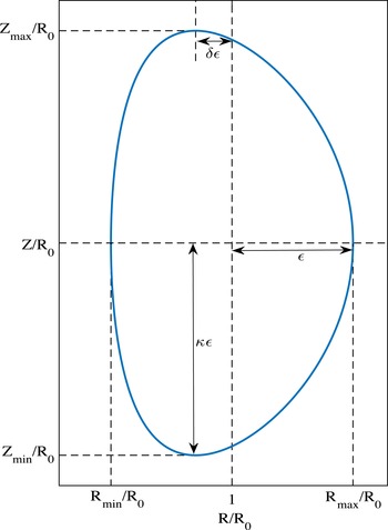
 $$\begin{eqnarray}\displaystyle & \displaystyle X=1+{\it\varepsilon}\cos ({\it\tau}+{\it\delta}_{0}\sin {\it\tau}) & \displaystyle\end{eqnarray}$$
 $$\begin{eqnarray}\displaystyle & \displaystyle Y={\it\varepsilon}{\it\kappa}\sin {\it\tau}. & \displaystyle\end{eqnarray}$$
 ${\it\varepsilon}=a/R_{0}$
is the inverse aspect ratio,
 ${\it\kappa}$
is the elongation and
 ${\it\delta}=\sin {\it\delta}_{0}$
is the triangularity. The geometry is illustrated in figure 1.
Geometry of the plasma equilibrium.

In practice the
 $c_{j}$
are determined by requiring that the exact plasma surface
 ${\it\Psi}=0$
, plus its slope and curvature match the model surface at three points: (i) the outer equatorial point, (ii) the inner equatorial point, and (iii) the high point maximum. Taking into account the up–down symmetry we see that the requirements translate to
 $$\begin{eqnarray}\displaystyle & \displaystyle {\it\Psi}(1+{\it\varepsilon},0)=0\quad \text{outer equatorial point}, & \displaystyle\end{eqnarray}$$
 $$\begin{eqnarray}\displaystyle & \displaystyle {\it\Psi}(1-{\it\varepsilon},0)=0\quad \text{inner equatorial point}, & \displaystyle\end{eqnarray}$$
 $$\begin{eqnarray}\displaystyle & \displaystyle {\it\Psi}(1-{\it\delta}{\it\varepsilon},{\it\kappa}{\it\varepsilon})=0\quad \text{high point}, & \displaystyle\end{eqnarray}$$
 $$\begin{eqnarray}\displaystyle & \displaystyle {\it\Psi}_{X}(1-{\it\delta}{\it\varepsilon},{\it\kappa}{\it\varepsilon})=0\quad \text{high point maximum}, & \displaystyle\end{eqnarray}$$
 $$\begin{eqnarray}\displaystyle & \displaystyle {\it\Psi}_{YY}(1+{\it\varepsilon},0)=-N_{1}{\it\Psi}_{X}(1+{\it\varepsilon},0)\quad \text{outer equatorial point curvature}, & \displaystyle\end{eqnarray}$$
 $$\begin{eqnarray}\displaystyle & \displaystyle {\it\Psi}_{YY}(1-{\it\varepsilon},0)=-N_{2}{\it\Psi}_{X}(1-{\it\varepsilon},0)\quad \text{inner equatorial point curvature}, & \displaystyle\end{eqnarray}$$
 $$\begin{eqnarray}\displaystyle & \displaystyle {\it\Psi}_{XX}(1-{\it\delta}{\it\varepsilon},{\it\kappa}{\it\varepsilon})=-N_{3}{\it\Psi}_{Y}(1-{\it\delta}{\it\varepsilon},{\it\kappa}{\it\varepsilon})\quad \text{high point curvature}, & \displaystyle\end{eqnarray}$$
 $$\begin{eqnarray}\displaystyle \displaystyle N_{1} & = & \displaystyle \left[\frac{\text{d}^{2}X}{\text{d}Y^{2}}\right]_{{\it\tau}=0}=-\frac{\left(1+{\it\delta}_{0}\right)^{2}}{{\it\varepsilon}{\it\kappa}^{2}}\end{eqnarray}$$
 $$\begin{eqnarray}\displaystyle \displaystyle N_{2} & = & \displaystyle \left[\frac{\text{d}^{2}X}{\text{d}Y^{2}}\right]_{{\it\tau}={\rm\pi}}=\frac{\left(1-{\it\delta}_{0}\right)^{2}}{{\it\varepsilon}{\it\kappa}^{2}}\end{eqnarray}$$
 $$\begin{eqnarray}\displaystyle \displaystyle N_{3} & = & \displaystyle \left[\frac{\text{d}^{2}Y}{\text{d}X^{2}}\right]_{{\it\tau}={\rm\pi}/2}=-\frac{{\it\kappa}}{{\it\varepsilon}\cos ^{2}{\it\delta}_{0}}.\end{eqnarray}$$
 $c_{j}$
has been reduced to finding the solution to a set of seven linear, inhomogeneous, algebraic equations; a very simple numerical problem. Hereafter, we assume that the
 $c_{j}$
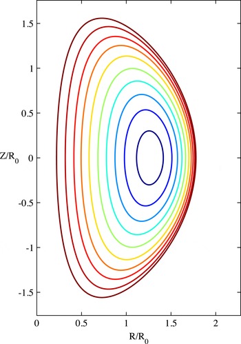
have been determined, thereby completely defining the equilibrium solution. A typical set of flux surfaces corresponding to the high
 ${\it\beta}$
, tight aspect ratio NSTX spherical tokamak is illustrated in figure 2, where
 $A$
has been chosen so that
 $J_{{\it\phi}}(1-{\it\varepsilon},0)=0$
. The surfaces look quite reasonable and, as expected, exhibit a large shift of the magnetic axis.
Flux surfaces for NSTX using the Solov’ev model. The value of
 $A$
has been chosen such that
 $J_{{\it\phi}}(1-{\it\varepsilon},0)=0$
.

The one final piece of information required for the resistive wall stability analysis is the value of poloidal beta
 ${\it\beta}_{p}$
. In general
 ${\it\beta}_{p}$
and the toroidal current
 $I$
can be expressed in terms of the free constants
 $A,{\it\Psi}_{0}$
. The advantage of the normalizations introduced by (2.3) is that
 ${\it\beta}_{p}$
is only a function of
 $A$
but not
 ${\it\Psi}_{0}$
. This can be seen by noting that the average pressure and toroidal current can be written as,
-
(i) Average pressure:
(2.10a ) $$\begin{eqnarray}\displaystyle & \displaystyle \bar{p}\equiv \frac{\displaystyle \int p\,\text{d}\boldsymbol{r}}{\displaystyle \int \text{d}\boldsymbol{r}}=-\frac{2{\rm\pi}{\it\Psi}_{0}^{2}(1-A)}{{\it\mu}_{0}R_{0}V}\int {\it\Psi}X\,\text{d}X\,\text{d}Y & \displaystyle\end{eqnarray}$$
(2.10b )
$$\begin{eqnarray}\displaystyle & \displaystyle V=\int \text{d}\boldsymbol{r}=2{\rm\pi}R_{0}^{3}\int X\,\text{d}X\,\text{d}Y. & \displaystyle\end{eqnarray}$$
-
(ii) Toroidal current:
(2.11)where
$$\begin{eqnarray}{\it\mu}_{0}I=\oint _{{\it\Psi}=0}B_{p}\text{d}l=\int _{{\it\Psi}\leqslant 0}{\it\mu}_{0}J_{{\it\phi}}\text{d}S=-\frac{{\it\Psi}_{0}}{R_{0}}\int _{{\it\Psi}\leqslant 0}\frac{1}{X}[A+(1-A)X^{2}]\,\text{d}X\,\text{d}Y,\end{eqnarray}$$
$B_{p}$
is the magnitude of the poloidal magnetic field. We now define
${\it\beta}_{p}$
as Substituting for(2.12a )
$$\begin{eqnarray}\displaystyle & \displaystyle {\it\beta}_{p}\equiv \frac{2{\it\mu}_{0}\bar{p}}{\bar{B}_{p}^{2}} & \displaystyle\end{eqnarray}$$
(2.12b )
$$\begin{eqnarray}\displaystyle & \displaystyle \bar{B}_{p}=\frac{\displaystyle \oint _{{\it\Psi}=0}B_{p}\,\text{d}l}{\displaystyle \oint _{{\it\Psi}=0}\text{d}l}=\frac{{\it\mu}_{0}I}{L_{P}} & \displaystyle\end{eqnarray}$$
(2.12c )
$$\begin{eqnarray}\displaystyle & \displaystyle L_{P}=\oint _{{\it\Psi}=0}\text{d}l. & \displaystyle\end{eqnarray}$$
$\bar{p}$
and
$I$
yields (2.13)Since
$$\begin{eqnarray}{\it\beta}_{p}=-\frac{4{\rm\pi}R_{0}L_{P}^{2}}{V}\frac{(1-A)\displaystyle \int _{{\it\Psi}\leqslant 0}{\it\Psi}X\,\text{d}X\,\text{d}Y}{\left\{\displaystyle \int _{{\it\Psi}\leqslant 0}\frac{1}{X}[A+(1-A)X^{2}]\,\text{d}X\,\text{d}Y\right\}^{2}}.\end{eqnarray}$$
${\it\Psi}$
is a function of
$A$
but not
${\it\Psi}_{0}$
, it follows that, as stated,
${\it\beta}_{p}={\it\beta}_{p}(A,{\it\varepsilon},{\it\kappa},{\it\delta})$
. Note also that the volume
$V$
and poloidal plasma circumference
$L_{P}$
are purely geometric factors that can be calculated from the solution given by (2.6) once the
$c_{j}$
have been determined. Furthermore, with our normalizations, the ratio
$R_{0}L_{P}^{2}/V$
is independent of
$R_{0}$
and
${\it\Psi}_{0}$
; that is
$R_{0}L_{P}^{2}/V=f(A,{\it\varepsilon},{\it\kappa},{\it\delta})$
. This completes the discussion of the equilibrium.


3. Resistive wall stability formulation
In this section we derive a variational principle describing the stability of
 $n=0$
resistive wall modes in a tokamak. The analysis starts from the ideal MHD normal mode equation for plasma stability. To obtain the variational principle we will need to decompose the volume surrounding the plasma into three regions: an interior vacuum region, a thin wall and an exterior vacuum region (Haney & Freidberg Reference Haney and Freidberg1989). The final variational principle is expressed in terms of three perturbed flux functions for the (i) plasma, (ii) interior vacuum region, and (iii) exterior vacuum region. To obtain this variational principle use is made of two natural boundary conditions.
The final step in the formulation is to derive relationships between the two perturbed vacuum fluxes and the perturbed plasma flux, a task accomplished by the application of Green’s theorem. The analysis is somewhat simplified by focusing on up–down symmetric equilibria and considering only vertical-type displacements, which are the most dangerous experimentally. The final form of the variational principle is straightforward to evaluate numerically and, most importantly, directly takes into account the feedback constraint
 ${\it\gamma}{\it\tau}_{w}=\text{constant}$
as described in the introduction.
The variational formulation, when implemented numerically, allows us to determine the maximum elongation and corresponding triangularity as a function of aspect ratio.
3.1. The basic ideal MHD stability equations
The starting point for the analysis is the ideal MHD linear stability equations for the plasma given by
 $$\begin{eqnarray}\displaystyle & \displaystyle {\it\omega}^{2}{\it\rho}{\bf\xi}+\boldsymbol{F}({\bf\xi})=0, & \displaystyle\end{eqnarray}$$
 $$\begin{eqnarray}\displaystyle & \displaystyle \boldsymbol{F}({\bf\xi})=\boldsymbol{J}_{1}\times \boldsymbol{B}+\boldsymbol{J}\times \boldsymbol{B}_{1}-\boldsymbol{{\rm\nabla}}p_{1}, & \displaystyle\end{eqnarray}$$
 $$\begin{eqnarray}\displaystyle & \displaystyle \boldsymbol{B}_{1}=\boldsymbol{{\rm\nabla}}\times ({\bf\xi}_{\bot }\times \boldsymbol{B}), & \displaystyle\end{eqnarray}$$
 $$\begin{eqnarray}\displaystyle & \displaystyle {\it\mu}_{0}\boldsymbol{J}_{1}=\boldsymbol{{\rm\nabla}}\times \boldsymbol{{\rm\nabla}}\times ({\bf\xi}_{\bot }\times \boldsymbol{B}), & \displaystyle\end{eqnarray}$$
 $$\begin{eqnarray}\displaystyle & \displaystyle p_{1}=-{\bf\xi}_{\bot }\boldsymbol{\cdot }\boldsymbol{{\rm\nabla}}p-{\it\gamma}p\boldsymbol{{\rm\nabla}}\boldsymbol{\cdot }{\bf\xi}, & \displaystyle\end{eqnarray}$$
 ${\bf\xi}$
is the plasma displacement vector and quantities with a 1 subscript represent first order perturbations (see for instance Freidberg (Reference Freidberg2014) and references therein). For resistive wall modes, the inertial effects can be neglected because the corresponding growth rates are very slow compared to the characteristic MHD time
 $a/V_{Ti}$
where
 $V_{Ti}$
is the ion thermal speed. Thus, the plasma behaviour is described by
 $$\begin{eqnarray}\boldsymbol{F}({\bf\xi})=0.\end{eqnarray}$$
In other words, referring to the general ideal MHD formulation of the energy principle only
 ${\it\delta}W({\bf\xi}^{\ast },{\bf\xi})$
is needed to describe the plasma behaviour, and
 ${\it\omega}^{2}K({\bf\xi}^{\ast },{\bf\xi})$
can be ignored.
Next, form the total energy integral
 ${\it\delta}W$
in the usual way:
 $$\begin{eqnarray}{\it\delta}W=-\frac{1}{2}\int {\bf\xi}^{\ast }\boldsymbol{\cdot }\boldsymbol{F}({\bf\xi})\,\text{d}\boldsymbol{r}=0.\end{eqnarray}$$
Using standard analysis (Sykes et al. Reference Sykes, Ahn, Akers, Arends, Carolan, Counsell, Fielding, Gryaznevich, Martin and Price2001) we can rewrite (3.3) as follows
 $$\begin{eqnarray}\displaystyle & \displaystyle {\it\delta}W({\bf\xi}^{\ast },{\bf\xi})={\it\delta}W_{F}({\bf\xi}^{\ast },{\bf\xi})+\text{BT}=0, & \displaystyle\end{eqnarray}$$
 $$\begin{eqnarray}\displaystyle & \displaystyle {\it\delta}W_{F}({\bf\xi}^{\ast },{\bf\xi})=\frac{1}{2{\it\mu}_{0}}\int [|\boldsymbol{Q}|^{2}+{\it\gamma}{\it\mu}_{0}p|\boldsymbol{{\rm\nabla}}\boldsymbol{\cdot }{\bf\xi}|^{2}-{\it\mu}_{0}{\bf\xi}_{\bot }^{\ast }\boldsymbol{\cdot }\boldsymbol{J}\times \boldsymbol{Q}+{\it\mu}_{0}({\bf\xi}_{\bot }\boldsymbol{\cdot }\boldsymbol{{\rm\nabla}}p)(\boldsymbol{{\rm\nabla}}\boldsymbol{\cdot }{\bf\xi}_{\bot }^{\ast })]\,\text{d}\boldsymbol{r}, & \displaystyle \nonumber\\ \displaystyle & & \displaystyle\end{eqnarray}$$
 $$\begin{eqnarray}\displaystyle & \displaystyle \text{BT}=\frac{1}{2{\it\mu}_{0}}\int _{S_{P}}(\boldsymbol{n}\boldsymbol{\cdot }{\bf\xi}_{\bot }^{\ast })[\boldsymbol{B}\boldsymbol{\cdot }\boldsymbol{Q}-{\it\gamma}{\it\mu}_{0}p\boldsymbol{{\rm\nabla}}\boldsymbol{\cdot }{\bf\xi}-{\it\mu}_{0}{\bf\xi}_{\bot }\boldsymbol{\cdot }\boldsymbol{{\rm\nabla}}p]\,\text{d}S_{P}, & \displaystyle\end{eqnarray}$$
 $\boldsymbol{Q}=\boldsymbol{{\rm\nabla}}\times ({\bf\xi}_{\bot }\times \boldsymbol{B})$
,
 $\boldsymbol{n}$
is the outward unit surface normal vector, and the surface integral in
 $\text{BT}$
is evaluated on the plasma surface
 $S_{P}$
given by
 ${\it\Psi}=0$
. This form is general, and in particular is valid for
 $n=0$
modes in a tokamak with arbitrary profiles.
Many researchers have long believed that
 $n=0$
stability is closely related to the problem of neighbouring equilibria of the Grad–Shafranov equation. This is indeed a correct belief, although to the authors’ knowledge, a derivation of this connection has not appeared in the literature. We have derived a relationship which explicitly shows this connection. The analysis is somewhat lengthy and is given in appendix A. The final result is a simplified form of
 ${\it\delta}W_{F}$
valid for up–down symmetric tokamaks undergoing vertical-like displacements; that is displacements for which
 ${\it\xi}_{Z}(R,Z)={\it\xi}_{Z}(R,-Z)$
and
 ${\it\xi}_{R}(R,Z)=-{\it\xi}_{R}(R,-Z)$
, (e.g.
 ${\it\xi}_{Z}={\it\xi}_{0}=\text{constant},{\it\xi}_{R}=0$
). Because of up–down symmetry, these displacements exactly decouple from the horizontal-like displacements for which
 ${\it\xi}_{Z}(R,Z)=-{\it\xi}_{Z}(R,-Z),{\it\xi}_{R}(R,Z)={\it\xi}_{R}(R,-Z)$
. In addition, it is shown in appendix A that the most unstable displacements are incompressible;
 $\boldsymbol{{\rm\nabla}}\boldsymbol{\cdot }{\bf\xi}=0$
Note also that for the
 $n=0$
mode in an up–down symmetric tokamak, it follows that
 ${\bf\xi}$
is purely real.
The simplified form of
 ${\it\delta}W_{F}$
is conveniently expressed in terms of the perturbed plasma flux
 ${\it\psi}$
which is related to the displacement vector by
 $$\begin{eqnarray}{\it\psi}=-{\bf\xi}_{\bot }\boldsymbol{\cdot }\boldsymbol{{\rm\nabla}}{\it\Psi}.\end{eqnarray}$$
The resulting form of
 ${\it\delta}W_{F}$
, valid for arbitrary equilibrium profiles, is given by
 $$\begin{eqnarray}\displaystyle {\it\delta}W_{F}=\frac{1}{2{\it\mu}_{0}}\int \left[\frac{(\boldsymbol{{\rm\nabla}}{\it\psi})^{2}}{R^{2}}-\left({\it\mu}_{0}p^{\prime \prime }+\frac{1}{2R^{2}}F^{2\prime \prime }\right){\it\psi}^{2}\right]\,\text{d}\boldsymbol{r}+\frac{1}{2{\it\mu}_{0}}\int _{S_{P}}\left(\frac{{\it\mu}_{0}J_{{\it\phi}}}{R^{2}B_{p}}{\it\psi}^{2}\right)\,\text{d}S_{P}, & & \displaystyle \nonumber\\ \displaystyle & & \displaystyle\end{eqnarray}$$
where, as before, a prime denotes a derivative with respect to the poloidal flux function, i.e.
 $\text{d}/\text{d}{\it\Psi}$
. Note that
 ${\it\delta}W_{F}$
is already written in self-adjoint form.
The connection to Grad–Shafranov neighbouring equilibria is now apparent. The differential equation in
 ${\it\psi}$
obtained by setting the variation in
 ${\it\delta}W_{F}$
to zero is identical to the neighbouring equilibrium equation obtained by letting
 ${\it\Psi}\rightarrow {\it\Psi}+{\it\psi}$
in the Grad–Shafranov equation and setting the first-order contribution to zero.
Observe that there is a boundary term arising from several integrations by parts in the derivation. This term is often zero since
 $J_{{\it\phi}}(S)=0$
on the plasma surface for many realistic profiles. However, it is non-zero for the Solov’ev profiles since the edge current density is finite and is, in fact, the main drive for vertical instabilities. To compensate this difficulty note that
 $p^{\prime \prime }=F^{2\prime \prime }=0$
for the Solov’ev profiles, implying that the volume contribution to
 ${\it\delta}W_{F}$
reduces to that of a vacuum field. In other words, the perturbed toroidal current density in the plasma is zero for the Solov’ev profiles. This simplification greatly outweighs the difficulty of maintaining the surface contribution. Specifically, it will ultimately allow us to make use of an analytic form of the Green’s function for the plasma region when evaluating
 ${\it\delta}W_{F}$
, a mathematical advantage that does not apply to general profiles.
The task now is to evaluate and simplify the boundary term
 $\text{BT}$
, recasting it in a form that is automatically self-adjoint.
3.2. The inner vacuum region
The first step in the simplification of
 $\text{BT}$
in (3.4) focuses on the inner vacuum region between the plasma and the resistive wall. By making use of incompressibility and rewriting (3.5) as
 $\boldsymbol{n}\boldsymbol{\cdot }{\bf\xi}_{\bot }={\it\psi}/RB_{p}$
where
 $\boldsymbol{n}$
is the unit normal vector to the plasma surface, we see that the boundary term reduces to
 $$\begin{eqnarray}\text{BT}=-\frac{1}{2{\it\mu}_{0}}\int \frac{{\it\psi}}{RB_{p}}(\boldsymbol{B}\boldsymbol{\cdot }\boldsymbol{Q}-{\it\mu}_{0}{\bf\xi}_{\bot }\boldsymbol{\cdot }\boldsymbol{{\rm\nabla}}p)\,\text{d}S_{P}.\end{eqnarray}$$
Next, assume that the perturbed magnetic field in the inner vacuum region is also written in terms of a flux function
 $\hat{{\it\psi}}_{i}$
. This is convenient because the previous analysis for the plasma region in terms of
 ${\it\psi}$
is directly applicable to the inner vacuum region by simply setting the equilibrium
 $\boldsymbol{J}=p=0$
in the vacuum region.
Now, the jump conditions across
 $S_{P}$
require that (for incompressible displacements and no surface currents) (Sykes et al.
Reference Sykes, Ahn, Akers, Arends, Carolan, Counsell, Fielding, Gryaznevich, Martin and Price2001)
 $$\begin{eqnarray}\displaystyle & \displaystyle \hat{{\it\psi}}_{i}|_{S_{P}}={\it\psi}|_{S_{P}}, & \displaystyle\end{eqnarray}$$
 $$\begin{eqnarray}\displaystyle & \displaystyle \hat{\boldsymbol{B}}\boldsymbol{\cdot }\hat{\boldsymbol{B}}_{i}|_{S_{P}}=(\boldsymbol{B}\boldsymbol{\cdot }\boldsymbol{Q}-{\it\mu}_{0}{\bf\xi}_{\bot }\boldsymbol{\cdot }\boldsymbol{{\rm\nabla}}p)|_{S_{P}}, & \displaystyle\end{eqnarray}$$
 $\hat{\boldsymbol{B}}$
the equilibrium vacuum field in the inner vacuum region. At this point, the first natural boundary condition is introduced into the formulation by substituting (3.8) into (3.7)
 $$\begin{eqnarray}\text{BT}=-\frac{1}{2{\it\mu}_{0}}\int _{S_{P}}\frac{\hat{{\it\psi}}_{i}}{RB_{p}}(\hat{\boldsymbol{B}}\boldsymbol{\cdot }\hat{\boldsymbol{B}}_{i})\,\text{d}S.\end{eqnarray}$$
Continuing, in the inner vacuum region the total (i.e. equilibrium plus perturbation) magnetic field can be written as
 $$\begin{eqnarray}\hat{\boldsymbol{B}}_{Tot}=\frac{1}{R}\boldsymbol{{\rm\nabla}}(\hat{{\it\Psi}}+\hat{{\it\psi}}_{i})\times \boldsymbol{e}_{{\it\phi}}+\frac{\hat{F}(\hat{{\it\Psi}}+\hat{{\it\psi}}_{i})}{R}\boldsymbol{e}_{{\it\phi}}.\end{eqnarray}$$
Since
 $\hat{F}(\hat{{\it\Psi}}+\hat{{\it\psi}}_{i})=R_{0}B_{0}=\text{ constant}$
in a vacuum region it follows that the perturbation
 $\hat{F}_{i}=(\partial \hat{F}/\partial \hat{{\it\Psi}})\hat{{\it\psi}}_{i}=0$
. Thus the perturbed magnetic field in the inner vacuum region for an
 $n=0$
perturbation is given by
 $$\begin{eqnarray}\hat{\boldsymbol{B}}_{i}=\frac{1}{R}\boldsymbol{{\rm\nabla}}\hat{{\it\psi}}_{i}\times \boldsymbol{e}_{{\it\phi}},\end{eqnarray}$$
from which it follows that
 $$\begin{eqnarray}\hat{\boldsymbol{B}}\boldsymbol{\cdot }\hat{\boldsymbol{B}}_{i}|_{S_{P}}=\frac{1}{R^{2}}(\boldsymbol{{\rm\nabla}}{\it\Psi}\boldsymbol{\cdot }\boldsymbol{{\rm\nabla}}\hat{{\it\psi}}_{i})|_{S_{P}}=\frac{B_{p}}{R}(\boldsymbol{n}\boldsymbol{\cdot }\boldsymbol{{\rm\nabla}}\hat{{\it\psi}}_{i})|_{S_{P}}.\end{eqnarray}$$
Here we have used the equilibrium continuity relation
 $\hat{\boldsymbol{B}}(S_{P})=\boldsymbol{B}(S_{P})$
which is valid when no surface currents are present. The boundary term can thus be written as
 $$\begin{eqnarray}\text{BT}=-\frac{1}{2{\it\mu}_{0}}\int _{S_{P}}\frac{1}{R^{2}}\hat{{\it\psi}}_{i}(\boldsymbol{n}\boldsymbol{\cdot }\boldsymbol{{\rm\nabla}}\hat{{\it\psi}}_{i})\,\text{d}S_{P}.\end{eqnarray}$$
The last part of this first step is to recognize that the magnetic energy in the inner vacuum region (with subscript
 $i$
) can be written as
 $$\begin{eqnarray}{\it\delta}W_{V_{I}}=\frac{1}{2{\it\mu}_{0}}\int (\hat{\boldsymbol{B}}_{i})^{2}\,\text{d}\boldsymbol{r}=\frac{1}{2{\it\mu}_{0}}\int \frac{(\boldsymbol{{\rm\nabla}}\hat{{\it\psi}}_{i})^{2}}{R^{2}}\,\text{d}\boldsymbol{r},\end{eqnarray}$$
with
 $\hat{{\it\psi}}_{i}$
satisfying
 $$\begin{eqnarray}{\it\Delta}^{\ast }\hat{{\it\psi}}_{i}=0.\end{eqnarray}$$
Using (3.15) we can easily convert (3.14) into two surface integrals, one on the plasma surface
 $S_{P}$
and the other on the inner wall surface
 $S_{W}$
,
 $$\begin{eqnarray}{\it\delta}W_{V_{I}}=\frac{1}{2{\it\mu}_{0}}\int \frac{(\boldsymbol{{\rm\nabla}}\hat{{\it\psi}}_{i})^{2}}{R^{2}}\,\text{d}\boldsymbol{r}=\frac{1}{2{\it\mu}_{0}}\int _{S_{W}}\frac{1}{R^{2}}\hat{{\it\psi}}_{i}(\boldsymbol{n}\boldsymbol{\cdot }\boldsymbol{{\rm\nabla}}\hat{{\it\psi}}_{i})\,\text{d}S_{W}-\frac{1}{2{\it\mu}_{0}}\int _{S_{P}}\frac{1}{R^{2}}\hat{{\it\psi}}_{i}(\boldsymbol{n}\boldsymbol{\cdot }\boldsymbol{{\rm\nabla}}\hat{{\it\psi}}_{i})\,\text{d}S_{P}.\end{eqnarray}$$
Here and below,
 $\boldsymbol{n}$
always refers to an outward pointing normal. This relation allows us to write (3.13) as
 $$\begin{eqnarray}\text{BT}={\it\delta}W_{V_{I}}-\frac{1}{2{\it\mu}_{0}}\int _{S_{W}}\frac{1}{R^{2}}\hat{{\it\psi}}_{i}(\boldsymbol{n}\boldsymbol{\cdot }\boldsymbol{{\rm\nabla}}\hat{{\it\psi}}_{i})\,\text{d}S_{W}.\end{eqnarray}$$
3.3. The outer vacuum region
The boundary term can be further simplified by introducing the magnetic energy in the outer vacuum region. In analogy with (3.14)–(3.16) we can write the outer vacuum energy (with subscript
 $o$
) as
 $$\begin{eqnarray}\displaystyle {\it\delta}W_{V_{O}} & = & \displaystyle \frac{1}{2{\it\mu}_{0}}\int (\hat{\boldsymbol{B}}_{o})^{2}\,\text{d}\boldsymbol{r}=\frac{1}{2{\it\mu}_{0}}\int \frac{(\boldsymbol{{\rm\nabla}}\hat{{\it\psi}}_{o})^{2}}{R^{2}}\,\text{d}\boldsymbol{r}\nonumber\\ \displaystyle & = & \displaystyle \frac{1}{2{\it\mu}_{0}}\int _{S_{\infty }}\frac{1}{R^{2}}\hat{{\it\psi}}_{o}(\boldsymbol{n}\boldsymbol{\cdot }\boldsymbol{{\rm\nabla}}\hat{{\it\psi}}_{o})\,\text{d}S_{\infty }-\frac{1}{2{\it\mu}_{0}}\int _{S_{W}}\frac{1}{R^{2}}\hat{{\it\psi}}_{o}(\boldsymbol{n}\boldsymbol{\cdot }\boldsymbol{{\rm\nabla}}\hat{{\it\psi}}_{o})\,\text{d}S_{W}.\end{eqnarray}$$
The contribution at the surface at infinity,
 $S_{\infty }$
, vanishes because of the regularity boundary condition far from the plasma. Thus, (3.18) reduces to
 $$\begin{eqnarray}{\it\delta}W_{V_{O}}+\frac{1}{2{\it\mu}_{0}}\int _{S_{W}}\frac{1}{R^{2}}\hat{{\it\psi}}_{o}(\boldsymbol{n}\boldsymbol{\cdot }\boldsymbol{{\rm\nabla}}\hat{{\it\psi}}_{o})\,\text{d}S_{W}=0.\end{eqnarray}$$
This expression is now added to (3.17) leading to
 $$\begin{eqnarray}\text{BT}={\it\delta}W_{V_{I}}+{\it\delta}W_{V_{O}}+\frac{1}{2{\it\mu}_{0}}\int _{S_{W}}\frac{1}{R^{2}}[\hat{{\it\psi}}_{o}(\boldsymbol{n}\boldsymbol{\cdot }\boldsymbol{{\rm\nabla}}\hat{{\it\psi}}_{o})-\hat{{\it\psi}}_{i}(\boldsymbol{n}\boldsymbol{\cdot }\boldsymbol{{\rm\nabla}}\hat{{\it\psi}}_{i})]\,\text{d}S_{W}.\end{eqnarray}$$
In (3.20), it is understood that the
 $\hat{{\it\psi}}_{i}$
terms are evaluated on the inner surface of the wall while the
 $\hat{{\it\psi}}_{o}$
terms are evaluated on the outer surface.
Equation (3.20) is in a convenient form since in the limit of a thin wall, the surface terms are ultimately transformed into a simple set of jump conditions arising from the solution for the fields within the resistive wall.
3.4. The fields within the resistive wall
The perturbed fields within the resistive wall are determined as follows. We write
 $$\begin{eqnarray}\displaystyle & \displaystyle \boldsymbol{B}_{w}=\boldsymbol{{\rm\nabla}}\times \boldsymbol{A}_{w} & \displaystyle\end{eqnarray}$$
 $$\begin{eqnarray}\displaystyle & \displaystyle \boldsymbol{E}_{w}=-{\it\gamma}\boldsymbol{A}_{w}-\boldsymbol{{\rm\nabla}}V_{w}=-{\it\gamma}\boldsymbol{A}_{w} & \displaystyle\end{eqnarray}$$
 $$\begin{eqnarray}\displaystyle & \displaystyle \boldsymbol{J}_{w}={\it\sigma}\boldsymbol{E}_{w}. & \displaystyle\end{eqnarray}$$
 ${\it\sigma}$
is the wall conductivity, the scalar electric potential
 $V_{w}$
has been set to zero as the gauge condition and all quantities are assumed to vary as
 $Q(\boldsymbol{r},t)=Q(\boldsymbol{r})\exp ({\it\gamma}t)$
. Ampere’s law then can be written as
 $$\begin{eqnarray}\boldsymbol{{\rm\nabla}}\times \boldsymbol{{\rm\nabla}}\times \boldsymbol{A}_{w}=-{\it\mu}_{0}{\it\sigma}{\it\gamma}\boldsymbol{A}_{w}.\end{eqnarray}$$
Now, form the dot product of (3.22) with
 $\boldsymbol{e}_{{\it\phi}}/R$
and define
 $\boldsymbol{A}_{w}\boldsymbol{\cdot }\boldsymbol{e}_{{\it\phi}}={\it\psi}_{w}/R$
. A short calculation for
 $n=0$
symmetry yields
 $$\begin{eqnarray}{\rm\nabla}^{2}{\it\psi}_{w}-\frac{2}{R}\boldsymbol{{\rm\nabla}}{\it\psi}_{w}\boldsymbol{\cdot }\boldsymbol{{\rm\nabla}}R={\it\mu}_{0}{\it\sigma}{\it\gamma}{\it\psi}_{w}.\end{eqnarray}$$
It is at this point that the thin wall approximation is introduced in order to obtain an analytic solution for
 ${\it\psi}_{w}$
. Assume that the wall thickness is denoted by
 $d$
while the minor radius of the wall at
 $Z=0$
is denoted by
 $b\sim L_{W}/2{\rm\pi}$
, where
 $L_{W}$
is the wall circumference. The thin wall approximation assumes that
 $d/b\ll 1$
. The thin wall ordering is then given by
 $$\begin{eqnarray}\displaystyle & \displaystyle {\it\mu}_{0}{\it\gamma}{\it\sigma}bd\sim {\it\gamma}{\it\tau}_{w}\sim 1 & \displaystyle\end{eqnarray}$$
 $$\begin{eqnarray}\displaystyle & \displaystyle \boldsymbol{n}\boldsymbol{\cdot }\boldsymbol{{\rm\nabla}}\sim \frac{1}{d} & \displaystyle\end{eqnarray}$$
 $$\begin{eqnarray}\displaystyle & \displaystyle \boldsymbol{t}\boldsymbol{\cdot }\boldsymbol{{\rm\nabla}}\sim \frac{1}{b}. & \displaystyle\end{eqnarray}$$
 ${\it\gamma}^{-1}\sim {\it\mu}_{0}{\it\sigma}bd\sim {\it\tau}_{w}$
is the characteristic diffusion time of magnetic flux through a wall of thickness
 $d$
and conductivity
 ${\it\sigma}$
into a vacuum region of thickness
 $b$
. The unit vector
 $\boldsymbol{n}$
is the outward normal to the wall and the ordering
 $\boldsymbol{n}\boldsymbol{\cdot }\boldsymbol{{\rm\nabla}}\sim 1/d$
implies rapid variation across the wall. Similarly, the unit vector
 $\boldsymbol{t}$
is tangential to the wall in the poloidal direction. The ordering
 $\boldsymbol{t}\boldsymbol{\cdot }\boldsymbol{{\rm\nabla}}\sim 1/b$
implies that tangential variation is slower (of the scale of the device size) than normal variation.
The analytic solution to (3.23) can now be obtained using the resistive wall analog of the ‘constant
 ${\it\psi}$
’ approximation that arises in tearing mode theory (Furth, Killeen & Rosenbluth Reference Furth, Killeen and Rosenbluth1963). We define a tangential poloidal arc length
 $l$
and a normal distance
 $s$
measured with respect to the inner surface of the resistive wall such that
 $0<s<d$
. This implies that
 $$\begin{eqnarray}\displaystyle & \displaystyle \boldsymbol{n}\boldsymbol{\cdot }\boldsymbol{{\rm\nabla}}=\frac{\partial }{\partial s} & \displaystyle\end{eqnarray}$$
 $$\begin{eqnarray}\displaystyle & \displaystyle \boldsymbol{t}\boldsymbol{\cdot }\boldsymbol{{\rm\nabla}}=\frac{\partial }{\partial l}. & \displaystyle\end{eqnarray}$$
 ${\it\psi}_{w}$
is then written as
 $$\begin{eqnarray}{\it\psi}_{w}(s,l)=\bar{{\it\psi}}(l)+\tilde{{\it\psi}}(s,l)+\cdots \,,\end{eqnarray}$$
where
 $\tilde{{\it\psi}}/\bar{{\it\psi}}\sim d/b$
. After some analysis, we find that the first non-vanishing contribution to (3.23) is given by
 $$\begin{eqnarray}\frac{\partial ^{2}\tilde{{\it\psi}}}{\partial s^{2}}={\it\mu}_{0}{\it\sigma}{\it\gamma}\bar{{\it\psi}}.\end{eqnarray}$$
This equation can be easily integrated leading to the following analytic solution for
 ${\it\psi}_{w}$
 $$\begin{eqnarray}{\it\psi}_{w}(s,l)=\left(1+{\it\mu}_{0}{\it\sigma}{\it\gamma}\frac{s^{2}}{2}+c_{1}+c_{2}\frac{s}{d}\right)\bar{{\it\psi}},\end{eqnarray}$$
where
 $c_{1}(l),c_{2}(l)$
are two free, order
 $d/b$
integration constants arising from the solution to (3.27).
The critical information to extract from these solutions is the change in
 ${\it\psi}_{w}$
and its normal derivative across the resistive wall. These values are given by
 $$\begin{eqnarray}\displaystyle & \displaystyle {\it\psi}_{w}(d,l)-{\it\psi}_{w}(0,l)=\bar{{\it\psi}}\left(\frac{{\it\alpha}d}{2}+c_{2}\right)\sim \frac{d}{b}\bar{{\it\psi}}\approx 0 & \displaystyle\end{eqnarray}$$
 $$\begin{eqnarray}\displaystyle & \displaystyle \boldsymbol{n}\boldsymbol{\cdot }\boldsymbol{{\rm\nabla}}{\it\psi}_{w}(d,l)-\boldsymbol{n}\boldsymbol{\cdot }\boldsymbol{{\rm\nabla}}{\it\psi}_{w}(0,l)=\frac{\partial {\it\psi}_{w}(d,l)}{\partial s}-\frac{\partial {\it\psi}_{w}(0,l)}{\partial s}={\it\alpha}\bar{{\it\psi}}. & \displaystyle\end{eqnarray}$$
 ${\it\alpha}={\it\gamma}{\it\mu}_{0}{\it\sigma}d\sim 1/b$
is related to the resistive wall growth time. Observe that there is a small, negligible, jump in the flux across the wall. There is, however, a finite jump in the normal derivative, representing the current flowing in the wall.
The information in (3.29) is related to the inner and outer vacuum solutions by recognizing that even though the wall is thin, it still has a small finite thickness. The implication of finite thickness is that there are no ideal infinitesimally thin surface currents on either face of the wall. Therefore, across each face of the wall, the flux and its normal derivative must be continuous with the adjacent vacuum fields. Specifically, coupling from the wall to the vacuum regions requires that
 $$\begin{eqnarray}\left.\hspace{-14.39996pt}\begin{array}{@{}ll@{}}\text{Inner surface} & \text{Outer surface}\\ \left[\hat{{\it\psi}}_{i}(s,l)-{\it\psi}_{w}(s,l)\right]_{s=0}=0 & \left[\hat{{\it\psi}}_{o}(s,l)-{\it\psi}_{w}(s,l)\right]_{s=d}=0\\ \left[\boldsymbol{n}\boldsymbol{\cdot }\boldsymbol{{\rm\nabla}}\hat{{\it\psi}}_{i}(s,l)-\boldsymbol{n}\boldsymbol{\cdot }\boldsymbol{{\rm\nabla}}{\it\psi}_{w}(s,l)\right]_{s=0}=0 & \left[\boldsymbol{n}\boldsymbol{\cdot }\boldsymbol{{\rm\nabla}}\hat{{\it\psi}}_{o}(s,l)-\boldsymbol{n}\boldsymbol{\cdot }\boldsymbol{{\rm\nabla}}{\it\psi}_{w}(s,l)\right]_{s=d}=0.\end{array}\right\}\end{eqnarray}$$
By combining (3.29) and (3.30), we obtain a set of jump conditions on the vacuum magnetic fields that takes into account the effects of the resistive wall. Simple substitution yields
 $$\begin{eqnarray}\displaystyle & \displaystyle \hat{{\it\psi}}_{o}(d,l)-\hat{{\it\psi}}_{i}(0,l)=0 & \displaystyle\end{eqnarray}$$
 $$\begin{eqnarray}\displaystyle & \displaystyle \boldsymbol{n}\boldsymbol{\cdot }\boldsymbol{{\rm\nabla}}\hat{{\it\psi}}_{o}(d,l)-\boldsymbol{n}\boldsymbol{\cdot }\boldsymbol{{\rm\nabla}}\hat{{\it\psi}}_{i}(0,l)={\it\alpha}\hat{{\it\psi}}_{i}(0,l). & \displaystyle\end{eqnarray}$$
3.5. The final variational principle
Return now to the expression for the boundary term given by (3.20). By substituting the top relation in (3.31) we obtain an expression for the boundary term in the thin wall limit that can be written as
 $$\begin{eqnarray}\text{BT}={\it\delta}W_{V_{I}}+{\it\delta}W_{V_{O}}+\frac{1}{2{\it\mu}_{0}}\int _{S_{W}}\frac{\hat{{\it\psi}}_{i}}{R^{2}}[(\boldsymbol{n}\boldsymbol{\cdot }\boldsymbol{{\rm\nabla}}\hat{{\it\psi}}_{o})-(\boldsymbol{n}\boldsymbol{\cdot }\boldsymbol{{\rm\nabla}}\hat{{\it\psi}}_{i})]\,\text{d}S_{W}.\end{eqnarray}$$
The second natural boundary condition is introduced into (3.32) by substituting the bottom relation from (3.31)
 $$\begin{eqnarray}\text{BT}={\it\delta}W_{V_{I}}+{\it\delta}W_{V_{O}}+\frac{{\it\alpha}}{2{\it\mu}_{0}}\int _{S_{W}}\frac{\hat{{\it\psi}}_{i}^{2}}{R^{2}}\,\text{d}S_{W}.\end{eqnarray}$$
Observe that the last term is now in a self-adjoint form.
By combining (3.33) with (3.4) we finally obtain the desired variational principle
 $$\begin{eqnarray}\displaystyle & \displaystyle {\it\delta}W={\it\delta}W_{F}+{\it\delta}W_{V_{I}}+{\it\delta}W_{V_{0}}+{\it\alpha}W_{D}=0 & \displaystyle\end{eqnarray}$$
 $$\begin{eqnarray}\displaystyle & \displaystyle {\it\delta}W_{F}=\frac{1}{2{\it\mu}_{0}}\int _{V_{P}}\left[\frac{(\boldsymbol{{\rm\nabla}}{\it\psi})^{2}}{R^{2}}-\left({\it\mu}_{0}p^{\prime \prime }+\frac{1}{2R^{2}}F^{2\prime \prime }\right){\it\psi}^{2}\right]\,\text{d}\boldsymbol{r}+\frac{1}{2{\it\mu}_{0}}\int _{S_{P}}\left(\frac{{\it\mu}_{0}J_{{\it\phi}}}{R^{2}B_{p}}{\it\psi}^{2}\right)\,\text{d}S_{P} & \displaystyle \nonumber\\ \displaystyle & & \displaystyle\end{eqnarray}$$
 $$\begin{eqnarray}\displaystyle & \displaystyle {\it\delta}W_{V_{I}}=\frac{1}{2{\it\mu}_{0}}\int _{V_{I}}\frac{(\boldsymbol{{\rm\nabla}}\hat{{\it\psi}}_{i})^{2}}{R^{2}}\,\text{d}\boldsymbol{r} & \displaystyle\end{eqnarray}$$
 $$\begin{eqnarray}\displaystyle & \displaystyle {\it\delta}W_{V_{O}}=\frac{1}{2{\it\mu}_{0}}\int _{V_{O}}\frac{(\boldsymbol{{\rm\nabla}}\hat{{\it\psi}}_{o})^{2}}{R^{2}}\,\text{d}\boldsymbol{r} & \displaystyle\end{eqnarray}$$
 $$\begin{eqnarray}\displaystyle & \displaystyle W_{D}=\frac{1}{2{\it\mu}_{0}}\int _{S_{W}}\frac{\hat{{\it\psi}}_{i}^{2}}{R^{2}}\,\text{d}S_{W}. & \displaystyle\end{eqnarray}$$
4. Summary
We have presented a general formulation of the
 $n=0$
resistive wall stability problem. The end result is a variational principle which, as shown in the accompanying paper, is quite amenable to numerical analysis. The key new feature introduced in the analysis is the presence of a feedback system. A simple but reliable measure of the effect of feedback is determined by calculating the maximum stable
 ${\it\kappa}$
and corresponding
 ${\it\delta}$
for fixed
 ${\it\gamma}{\it\tau}_{w}\propto {\it\alpha}b$
Footnote
1
. Numerical results obtained with this formalism and implications for reactor designs are given in the accompanying paper.
Acknowledgements
The authors would like to thank Professor D. Whyte (MIT) for providing the motivation for this work and for many insightful conversations. J. P. Lee and A. J. Cerfon were supported by the U.S. Department of Energy, Office of Science, Fusion Energy Sciences under Award Numbers DE-FG02-86ER53223 and DE-SC0012398. J. P. Freidberg was partially supported by the U.S. Department of Energy, Office of Science, Fusion Energy Sciences under Award Number DE-FG02-91ER54109.
Appendix A. Relation between MHD stability and neighbouring equilibria
A.1. Introduction
We present a derivation of the fluid contribution
 $({\it\delta}W_{F})$
to the total potential energy
 $({\it\delta}W)$
describing the
 $n=0$
stability of a tokamak. The derivation is presented for arbitrary profiles and then simplified at the end for the Solov’ev profiles. The derivation requires a substantial amount of analysis. However, the final result is quite simple and is shown to be directly related to neighbouring equilibria of the Grad–Shafranov equation.
A.2. The starting point
The starting point for the analysis is the expression for the total MHD potential energy
 ${\it\delta}W$
written in the ‘standard’ form (see (3.4)) (Sykes et al.
Reference Sykes, Ahn, Akers, Arends, Carolan, Counsell, Fielding, Gryaznevich, Martin and Price2001)
 $$\begin{eqnarray}\displaystyle & \displaystyle {\it\delta}W({\bf\xi}^{\ast },{\bf\xi})={\it\delta}W_{F}({\bf\xi}^{\ast },{\bf\xi})+\text{BT}, & \displaystyle\end{eqnarray}$$
 $$\begin{eqnarray}\displaystyle & \displaystyle {\it\delta}W_{F}({\bf\xi}^{\ast },{\bf\xi})=\frac{1}{2{\it\mu}_{0}}\int [|\boldsymbol{Q}|^{2}+{\it\gamma}{\it\mu}_{0}p|\boldsymbol{{\rm\nabla}}\boldsymbol{\cdot }{\bf\xi}|^{2}-{\it\mu}_{0}{\bf\xi}_{\bot }^{\ast }\boldsymbol{\cdot }\boldsymbol{J}\times \boldsymbol{Q}+{\it\mu}_{0}({\bf\xi}_{\bot }\boldsymbol{\cdot }\boldsymbol{{\rm\nabla}}p)(\boldsymbol{{\rm\nabla}}\boldsymbol{\cdot }{\bf\xi}_{\bot }^{\ast })]\,\text{d}\boldsymbol{r}, & \displaystyle \nonumber\\ \displaystyle & & \displaystyle\end{eqnarray}$$
 $$\begin{eqnarray}\displaystyle & \displaystyle \text{BT}=\frac{1}{2{\it\mu}_{0}}\int _{S_{P}}(\boldsymbol{n}\boldsymbol{\cdot }{\bf\xi}_{\bot }^{\ast })[\boldsymbol{B}\boldsymbol{\cdot }\boldsymbol{Q}-{\it\gamma}{\it\mu}_{0}p\boldsymbol{{\rm\nabla}}\boldsymbol{\cdot }{\bf\xi}-{\it\mu}_{0}{\bf\xi}_{\bot }\boldsymbol{\cdot }\boldsymbol{{\rm\nabla}}p]\,\text{d}S_{P}, & \displaystyle\end{eqnarray}$$
 $\boldsymbol{Q}=\boldsymbol{{\rm\nabla}}\times ({\bf\xi}_{\bot }\times \boldsymbol{B})$
. The quantity
 ${\it\delta}W_{F}$
is the fluid contribution while
 $\text{BT}$
is the boundary term that will ultimately be related to the vacuum energy and the resistive dissipated wall power. Note also that for the
 $n=0$
mode in an up–down symmetric tokamak we can assume that
 ${\bf\xi}$
is purely real.
The present analysis is focused solely on obtaining a simple form for
 ${\it\delta}W_{F}$
. Observe that even though our goal is to calculate the eigenvalue
 ${\it\omega}$
for resistive wall modes, we can neglect the
 ${\it\omega}^{2}$
contribution due to the plasma inertia. The reason is that resistive wall growth rates are much slower than ideal MHD growth rates, thus justifying the neglect of MHD inertial effects. This is the explanation of why only
 ${\it\delta}W({\bf\xi},{\bf\xi})$
and not
 ${\it\omega}^{2}K({\bf\xi},{\bf\xi})$
is needed to describe the plasma behaviour. The eigenvalue
 ${\it\omega}$
will appear in the evaluation of
 $\text{BT}$
.
A.3. Incompressibility
The first step in the analysis is to examine the plasma compressibility term. As is well known this is the only term in which
 ${\it\xi}_{\Vert }$
appears. The question is whether or not a well behaved
 ${\it\xi}_{\Vert }$
can be found that makes
 $\boldsymbol{{\rm\nabla}}\boldsymbol{\cdot }{\bf\xi}=0$
which, if possible, clearly minimizes the plasma compressibility term.
To answer this question we have to make use of the following symmetries with respect to the
 $Z$
dependence of the equilibrium magnetic fields
 $$\begin{eqnarray}\displaystyle & \displaystyle B_{R}(R,-Z)=-B_{R}(R,Z) & \displaystyle\end{eqnarray}$$
 $$\begin{eqnarray}\displaystyle & \displaystyle B_{Z}(R,-Z)=+B_{Z}(R,Z) & \displaystyle\end{eqnarray}$$
 $$\begin{eqnarray}\displaystyle & \displaystyle B_{{\it\phi}}(R,-Z)=+B_{{\it\phi}}(R,Z). & \displaystyle\end{eqnarray}$$
 $n=0$
mode, a general perturbation
 ${\bf\xi}$
can be always be written as the sum of an ‘even
 ${\it\xi}_{Z}$
’ contribution plus an ‘odd
 ${\it\xi}_{Z}$
’ contribution, which are completely decoupled from one another because of the equilibrium symmetry. The perturbation symmetries are as follows,
 $$\begin{eqnarray}\left.\begin{array}{@{}ll@{}}\text{Even}~{\it\xi}_{Z}~\text{symmetry} & \text{Odd }{\it\xi}_{Z}~\text{symmetry}\\ {\it\xi}_{Z}(R,-Z)=+{\it\xi}_{Z}(R,Z) & {\it\xi}_{Z}(R,-Z)=-{\it\xi}_{Z}(R,Z)\\ {\it\xi}_{R}(R,-Z)=-{\it\xi}_{R}(R,Z) & {\it\xi}_{R}(R,-Z)=+{\it\xi}_{R}(R,Z)\\ {\it\xi}_{{\it\phi}}(R,-Z)=+{\it\xi}_{{\it\phi}}(R,Z) & {\it\xi}_{{\it\phi}}(R,-Z)=-{\it\xi}_{{\it\phi}}(R,Z)\\ {\it\xi}_{\Vert }(R,-Z)=+{\it\xi}_{\Vert }(R,Z) & {\it\xi}_{\Vert }(R,-Z)=-{\it\xi}_{\Vert }(R,Z)\\ \boldsymbol{{\rm\nabla}}\boldsymbol{\cdot }{\bf\xi}_{\bot }(R,-Z)=-\boldsymbol{{\rm\nabla}}\boldsymbol{\cdot }{\bf\xi}_{\bot }(R,-Z) & \boldsymbol{{\rm\nabla}}\boldsymbol{\cdot }{\bf\xi}_{\bot }(R,-Z)=+\boldsymbol{{\rm\nabla}}\boldsymbol{\cdot }{\bf\xi}_{\bot }(R,-Z).\end{array}\right\}\end{eqnarray}$$
The
 $n=0$
modes of interest have even
 ${\it\xi}_{Z}$
symmetry (e.g.
 ${\it\xi}_{Z}=\text{constant}$
) corresponding to ‘vertical displacements’. The less interesting modes have odd
 ${\it\xi}_{Z}$
symmetry (e.g.
 ${\it\xi}_{R}=\text{constant}$
) and represent ‘horizontal displacements’.
For the vertical displacements of interest, the most unstable modes are always incompressible. To show this we note that for a minimizing incompressible displacement
 ${\it\xi}_{\Vert }$
must satisfy
 $$\begin{eqnarray}\boldsymbol{B}\boldsymbol{\cdot }\boldsymbol{{\rm\nabla}}\frac{{\it\xi}_{\Vert }}{B}=\boldsymbol{B}_{p}\boldsymbol{\cdot }\boldsymbol{{\rm\nabla}}\frac{{\it\xi}_{\Vert }}{B}=B_{p}\frac{\partial }{\partial l}\frac{{\it\xi}_{\Vert }}{B}=-\boldsymbol{{\rm\nabla}}\boldsymbol{\cdot }{\bf\xi}_{\bot },\end{eqnarray}$$
where
 $\boldsymbol{B}_{p}$
is the poloidal magnetic field and
 $l$
is poloidal arc length. Thus, for
 ${\it\xi}_{\Vert }$
to be well behaved (i.e. be periodic) it must satisfy the periodicity constraint
 $$\begin{eqnarray}0=\oint \frac{\partial }{\partial l}\left(\frac{{\it\xi}_{\Vert }}{B}\right)\,\text{d}l=-\oint \frac{\boldsymbol{{\rm\nabla}}\boldsymbol{\cdot }{\bf\xi}_{\bot }}{B_{p}}\,\text{d}l=-\oint \frac{\boldsymbol{{\rm\nabla}}\boldsymbol{\cdot }{\bf\xi}_{\bot }}{B_{Z}}\,\text{d}Z.\end{eqnarray}$$
This constraint is automatically satisfied for the even
 ${\it\xi}_{Z}$
symmetry displacement.
The conclusion is that the plasma compressibility term in
 ${\it\delta}W_{F}$
is minimized by choosing
 ${\it\xi}_{\Vert }$
to satisfy (A 4) leading to the result
 ${\it\gamma}p(\boldsymbol{{\rm\nabla}}\boldsymbol{\cdot }{\bf\xi})^{2}=0$
. The remainder of
 ${\it\delta}W_{F}$
is only a function of
 ${\bf\xi}_{\bot }$
A.4. Reformulating
${\it\delta}W_{F}$
in terms of the vector potential

The evaluation of
 ${\it\delta}W_{F}$
is more conveniently carried out in terms of the perturbed vector potential
 $\boldsymbol{A}_{\bot 1}$
rather than the plasma displacement
 ${\bf\xi}_{\bot }$
. The familiar relation between these two quantities is
 $$\begin{eqnarray}\boldsymbol{A}_{\bot 1}={\bf\xi}_{\bot }\times \boldsymbol{B}\quad {\bf\xi}_{\bot }=\frac{\boldsymbol{B}\times \boldsymbol{A}_{\bot 1}}{B^{2}}.\end{eqnarray}$$
In general
 $\boldsymbol{A}_{\bot 1}$
can be vector decomposed as follows
 $$\begin{eqnarray}\boldsymbol{A}_{\bot 1}=f(R,Z)\boldsymbol{{\rm\nabla}}{\it\Psi}+g(R,Z)\boldsymbol{B}_{p}+h(R,Z)\boldsymbol{e}_{{\it\phi}}.\end{eqnarray}$$
Here,
 ${\it\Psi}(R,Z)$
is the equilibrium flux function satisfying the Grad–Shafranov equation. We next make use of the constraint
 $\boldsymbol{A}_{\bot 1}\boldsymbol{\cdot }\boldsymbol{B}=0$
and introduce the perturbed flux
 ${\it\psi}(R,Z)=RA_{{\it\phi}1}(R,Z)=Rh(R,Z)$
. A short calculation then enables us to rewrite
 $\boldsymbol{A}_{\bot 1}$
as
 $$\begin{eqnarray}\boldsymbol{A}_{\bot 1}=f\boldsymbol{{\rm\nabla}}{\it\Psi}-\frac{F{\it\psi}}{R^{2}B_{p}^{2}}\boldsymbol{B}_{p}+\frac{{\it\psi}}{R}\boldsymbol{e}_{{\it\phi}},\end{eqnarray}$$
where
 $F({\it\psi})=RB_{{\it\phi}}$
. The basic unknowns in the problem are
 ${\it\psi},f$
.
Before proceeding with the evaluation of
 ${\it\delta}W_{F}$
, it is useful to list a number of relations involving
 $\boldsymbol{A}_{\bot 1}$
that enter the analysis. These are relatively straightforward to derive:
 $$\begin{eqnarray}\displaystyle & \displaystyle \boldsymbol{Q}=\boldsymbol{{\rm\nabla}}\times \boldsymbol{A}_{\bot 1}=\frac{1}{R}\boldsymbol{{\rm\nabla}}{\it\psi}\times \boldsymbol{e}_{{\it\phi}}+\boldsymbol{{\rm\nabla}}f\times \boldsymbol{{\rm\nabla}}{\it\Psi}+\left[\frac{1}{R}\boldsymbol{{\rm\nabla}}{\it\Psi}\boldsymbol{\cdot }\boldsymbol{{\rm\nabla}}\left(\frac{F{\it\psi}}{R^{2}B_{p}^{2}}\right)-\frac{{\it\mu}_{0}J_{{\it\phi}}F{\it\psi}}{R^{2}B_{p}^{2}}\right]\boldsymbol{e}_{{\it\phi}}, & \displaystyle \nonumber\\ \displaystyle & & \displaystyle\end{eqnarray}$$
 $$\begin{eqnarray}\displaystyle & \displaystyle \boldsymbol{Q}\boldsymbol{\cdot }\boldsymbol{A}_{\bot 1}=\frac{{\it\psi}}{R}\left[\frac{1}{R}\boldsymbol{{\rm\nabla}}{\it\Psi}\boldsymbol{\cdot }\boldsymbol{{\rm\nabla}}\left(\frac{F{\it\psi}}{R^{2}B_{p}^{2}}\right)-\frac{{\it\mu}_{0}J_{{\it\phi}}F{\it\psi}}{R^{2}B_{p}^{2}}\right]-\frac{F{\it\psi}}{R^{4}B_{p}^{2}}\boldsymbol{{\rm\nabla}}{\it\Psi}\boldsymbol{\cdot }\boldsymbol{{\rm\nabla}}{\it\psi} & \displaystyle \nonumber\\ \displaystyle & \displaystyle \hspace{-30.0pt}\quad +\,2{\it\psi}(\boldsymbol{B}_{p}\boldsymbol{\cdot }\boldsymbol{{\rm\nabla}}f)-\boldsymbol{{\rm\nabla}}\boldsymbol{\cdot }({\it\psi}f\,\boldsymbol{B}_{p}), & \displaystyle\end{eqnarray}$$
 $$\begin{eqnarray}\displaystyle & \displaystyle \boldsymbol{Q}\boldsymbol{\cdot }\boldsymbol{B}=\frac{1}{R^{2}}\boldsymbol{{\rm\nabla}}{\it\Psi}\boldsymbol{\cdot }\boldsymbol{{\rm\nabla}}{\it\psi}+\frac{F}{R}\left[\frac{1}{R}\boldsymbol{{\rm\nabla}}{\it\Psi}\boldsymbol{\cdot }\boldsymbol{{\rm\nabla}}\left(\frac{F{\it\psi}}{R^{2}B_{p}^{2}}\right)-\frac{{\it\mu}_{0}J_{{\it\phi}}F{\it\psi}}{R^{2}B_{p}^{2}}\right]+F(\boldsymbol{B}_{p}\boldsymbol{\cdot }\boldsymbol{{\rm\nabla}}f), & \displaystyle\end{eqnarray}$$
 $$\begin{eqnarray}\displaystyle & \displaystyle \boldsymbol{{\rm\nabla}}{\it\psi}\boldsymbol{\cdot }(\boldsymbol{e}_{{\it\phi}}\times \boldsymbol{A}_{\bot 1})=-\frac{F{\it\psi}}{R^{3}B_{p}^{2}}\boldsymbol{{\rm\nabla}}{\it\Psi}\boldsymbol{\cdot }\boldsymbol{{\rm\nabla}}{\it\psi}-Rf\boldsymbol{B}_{p}\boldsymbol{\cdot }\boldsymbol{{\rm\nabla}}{\it\psi}, & \displaystyle\end{eqnarray}$$
 $$\begin{eqnarray}\displaystyle & \displaystyle {\bf\xi}_{\bot }\boldsymbol{\cdot }\boldsymbol{{\rm\nabla}}p=-p^{\prime }{\it\psi}, & \displaystyle\end{eqnarray}$$
 $$\begin{eqnarray}\displaystyle & \displaystyle \boldsymbol{A}_{\bot 1}\boldsymbol{\cdot }(\boldsymbol{{\rm\nabla}}{\it\Psi}\times \boldsymbol{B})=-B^{2}{\it\psi}, & \displaystyle\end{eqnarray}$$
 $\text{d}/\text{d}{\it\Psi}$
as in the main text. We are now ready to evaluate
 ${\it\delta}W_{F}$
A.5. Evaluation of
${\it\delta}W_{F}$

There are three terms appearing in
 ${\it\delta}W_{F}$
as given by (A 1) after setting
 $\boldsymbol{{\rm\nabla}}\boldsymbol{\cdot }{\bf\xi}=0$
. Using (A 9), these terms can be evaluated in a straightforward way. The magnetic energy term is given by
 $$\begin{eqnarray}\displaystyle (\boldsymbol{Q})^{2} & = & \displaystyle \frac{(\boldsymbol{{\rm\nabla}}{\it\psi})^{2}}{R^{2}}+\left[\frac{1}{R}\boldsymbol{{\rm\nabla}}{\it\Psi}\boldsymbol{\cdot }\boldsymbol{{\rm\nabla}}\left(\frac{F{\it\psi}}{R^{2}B_{p}^{2}}\right)-\frac{{\it\mu}_{0}J_{{\it\phi}}F{\it\psi}}{R^{2}B_{p}^{2}}\right]^{2}\nonumber\\ \displaystyle & & \displaystyle +\,(R\boldsymbol{B}_{p}\boldsymbol{\cdot }\boldsymbol{{\rm\nabla}}f)^{2}+2(R\boldsymbol{B}_{p}\boldsymbol{\cdot }\boldsymbol{{\rm\nabla}}f)\left[\frac{1}{R}\boldsymbol{{\rm\nabla}}{\it\Psi}\boldsymbol{\cdot }\boldsymbol{{\rm\nabla}}\left(\frac{F{\it\psi}}{R^{2}B_{p}^{2}}\right)-\frac{{\it\mu}_{0}J_{{\it\phi}}F{\it\psi}}{R^{2}B_{p}^{2}}\right].\end{eqnarray}$$
The current term is evaluated by making use of the equilibrium relation
 ${\it\mu}_{0}\boldsymbol{J}=F^{\prime }\boldsymbol{B}+{\it\mu}_{0}Rp^{\prime }\boldsymbol{e}_{{\it\phi}}$
which leads to a fairly complicated expression
 $$\begin{eqnarray}\displaystyle & & \displaystyle -{\bf\xi}_{\bot }\boldsymbol{\cdot }({\it\mu}_{0}\boldsymbol{J}\times \boldsymbol{Q})=-\left(F^{\prime }+F\frac{{\it\mu}_{0}p^{\prime }}{B^{2}}\right)(\boldsymbol{A}_{\bot 1}\boldsymbol{\cdot }\boldsymbol{Q})+\frac{{\it\mu}_{0}p^{\prime }}{B^{2}}{\it\psi}(\boldsymbol{B}\boldsymbol{\cdot }\boldsymbol{Q})\nonumber\\ \displaystyle & & \displaystyle \quad =-\hspace{-1.0pt}\left(F^{\prime }+F\frac{{\it\mu}_{0}p^{\prime }}{B^{2}}\right)\left\{\frac{{\it\psi}}{R}\left[\frac{1}{R}\boldsymbol{{\rm\nabla}}{\it\Psi}\boldsymbol{\cdot }\boldsymbol{{\rm\nabla}}\left(\frac{F{\it\psi}}{R^{2}B_{p}^{2}}\right)-\frac{{\it\mu}_{0}J_{{\it\phi}}F{\it\psi}}{R^{2}B_{p}^{2}}\right]\right.\nonumber\\ \displaystyle & & \displaystyle \hspace{-3.5pt}\qquad \left.\vphantom{\left[\left(\frac{F{\it\psi}}{R^{2}B_{p}^{2}}\right)-\frac{{\it\mu}_{0}J_{{\it\phi}}F{\it\psi}}{R^{2}B_{p}^{2}}\right]}-\,\frac{F{\it\psi}}{R^{4}B_{p}^{2}}\boldsymbol{{\rm\nabla}}{\it\Psi}\boldsymbol{\cdot }\boldsymbol{{\rm\nabla}}{\it\psi}+2\frac{{\it\psi}}{R}(R\boldsymbol{B}_{p}\boldsymbol{\cdot }\boldsymbol{{\rm\nabla}}f)-\boldsymbol{{\rm\nabla}}\boldsymbol{\cdot }({\it\psi}f\,\boldsymbol{B}_{p})\right\}\nonumber\\ \displaystyle & & \displaystyle \qquad +\,\frac{{\it\mu}_{0}p^{\prime }{\it\psi}}{B^{2}}\left\{\frac{1}{R^{2}}\boldsymbol{{\rm\nabla}}{\it\Psi}\boldsymbol{\cdot }\boldsymbol{{\rm\nabla}}{\it\psi}+\frac{F}{R}\left[\frac{1}{R}\boldsymbol{{\rm\nabla}}{\it\Psi}\boldsymbol{\cdot }\boldsymbol{{\rm\nabla}}\left(\frac{F{\it\psi}}{R^{2}B_{p}^{2}}\right)-\frac{{\it\mu}_{0}J_{{\it\phi}}F{\it\psi}}{R^{2}B_{p}^{2}}\right]\right.\nonumber\\ \displaystyle & & \displaystyle \hspace{-3.0pt}\qquad \left.\vphantom{\left[\left(\frac{F{\it\psi}}{R^{2}B_{p}^{2}}\right)-\frac{{\it\mu}_{0}J_{{\it\phi}}F{\it\psi}}{R^{2}B_{p}^{2}}\right]}+\,\frac{F}{R}(R\boldsymbol{B}_{p}\boldsymbol{\cdot }\boldsymbol{{\rm\nabla}}f)\right\}.\end{eqnarray}$$
The remaining pressure term requires some minor algebraic manipulations. The result is
 $$\begin{eqnarray}\displaystyle \hspace{-24.0pt} & & \displaystyle {\it\mu}_{0}({\bf\xi}_{\bot }\boldsymbol{\cdot }\boldsymbol{{\rm\nabla}}p)(\boldsymbol{{\rm\nabla}}\boldsymbol{\cdot }{\bf\xi}_{\bot })={\it\mu}_{0}\boldsymbol{{\rm\nabla}}\boldsymbol{\cdot }[({\bf\xi}_{\bot }\boldsymbol{\cdot }\boldsymbol{{\rm\nabla}}p){\bf\xi}_{\bot }]-{\it\mu}_{0}{\bf\xi}_{\bot }\boldsymbol{\cdot }\boldsymbol{{\rm\nabla}}({\bf\xi}_{\bot }\boldsymbol{\cdot }\boldsymbol{{\rm\nabla}}p)\nonumber\\ \displaystyle \hspace{-24.0pt} & & \displaystyle \quad =-{\it\mu}_{0}\boldsymbol{{\rm\nabla}}\boldsymbol{\cdot }(p^{\prime }{\it\psi}{\bf\xi}_{\bot })+\frac{{\it\mu}_{0}p^{\prime \prime }{\it\psi}}{B^{2}}[\boldsymbol{A}_{\bot 1}\boldsymbol{\cdot }(\boldsymbol{{\rm\nabla}}{\it\Psi}\times \boldsymbol{B})]+\frac{{\it\mu}_{0}p^{\prime }}{B^{2}}[\boldsymbol{A}_{\bot 1}\boldsymbol{\cdot }(\boldsymbol{{\rm\nabla}}{\it\psi}\times \boldsymbol{B})]\nonumber\\ \displaystyle \hspace{-24.0pt} & & \displaystyle \quad =-{\it\mu}_{0}\boldsymbol{{\rm\nabla}}\boldsymbol{\cdot }(p^{\prime }{\it\psi}{\bf\xi}_{\bot })-{\it\mu}_{0}p^{\prime \prime }{\it\psi}^{2}+\frac{{\it\mu}_{0}p^{\prime }F}{RB^{2}}[\boldsymbol{{\rm\nabla}}{\it\psi}\boldsymbol{\cdot }(\boldsymbol{e}_{{\it\phi}}\times \boldsymbol{A}_{\bot 1})]-\frac{{\it\mu}_{0}p^{\prime }{\it\psi}}{R^{2}B^{2}}(\boldsymbol{{\rm\nabla}}{\it\Psi}\boldsymbol{\cdot }\boldsymbol{{\rm\nabla}}{\it\psi})\nonumber\\ \displaystyle \hspace{-24.0pt} & & \displaystyle \quad =-{\it\mu}_{0}\boldsymbol{{\rm\nabla}}\boldsymbol{\cdot }(p^{\prime }{\it\psi}{\bf\xi}_{\bot })-{\it\mu}_{0}p^{\prime \prime }{\it\psi}^{2}-\frac{{\it\mu}_{0}p^{\prime }{\it\psi}}{R^{2}B_{p}^{2}}(\boldsymbol{{\rm\nabla}}{\it\Psi}\boldsymbol{\cdot }\boldsymbol{{\rm\nabla}}{\it\psi})-\frac{{\it\mu}_{0}p^{\prime }F}{RB^{2}}[f(R\boldsymbol{B}_{p}\boldsymbol{\cdot }\boldsymbol{{\rm\nabla}}{\it\psi})].\end{eqnarray}$$
The next task is to sum these three complicated contributions and simplify the result. The terms in the sum can be collected and written as follows
 $$\begin{eqnarray}\displaystyle & \displaystyle {\it\delta}W_{F}({\bf\xi},{\bf\xi})=\frac{1}{2{\it\mu}_{0}}\int [(\boldsymbol{Q})^{2}-{\it\mu}_{0}{\bf\xi}_{\bot }\boldsymbol{\cdot }\boldsymbol{J}\times \boldsymbol{Q}+{\it\mu}_{0}({\bf\xi}_{\bot }\boldsymbol{\cdot }\boldsymbol{{\rm\nabla}}p)(\boldsymbol{{\rm\nabla}}\boldsymbol{\cdot }{\bf\xi}_{\bot })]\,\text{d}\boldsymbol{r}=\frac{1}{2{\it\mu}_{0}}\int U\,\text{d}\boldsymbol{r} & \displaystyle \nonumber\\ \displaystyle & & \displaystyle\end{eqnarray}$$
 $$\begin{eqnarray}\displaystyle & \displaystyle U=U_{1}(f,f)+U_{2}(f,{\it\psi})+U_{3}({\it\psi},{\it\psi}). & \displaystyle\end{eqnarray}$$
Here, each
 $U_{j}$
is a combination of algebraic and differential operators acting on the terms appearing in the arguments. After a short calculation, the first two terms on the right-hand side can be simplified, leading to
 $$\begin{eqnarray}\displaystyle & & \displaystyle U_{1}(f,f)+U_{2}(f,{\it\psi})=(R\boldsymbol{B}_{p}\boldsymbol{\cdot }\boldsymbol{{\rm\nabla}}f)^{2}+\boldsymbol{{\rm\nabla}}\boldsymbol{\cdot }(F^{\prime }f{\it\psi}\boldsymbol{B}_{p})\nonumber\\ \displaystyle & & \displaystyle \qquad +\,2(R\boldsymbol{B}_{p}\boldsymbol{\cdot }\boldsymbol{{\rm\nabla}}f)\left[\frac{1}{R}\boldsymbol{{\rm\nabla}}{\it\Psi}\boldsymbol{\cdot }\boldsymbol{{\rm\nabla}}\left(\frac{F{\it\psi}}{R^{2}B_{p}^{2}}\right)-\frac{{\it\mu}_{0}J_{{\it\phi}}F{\it\psi}}{R^{2}B_{p}^{2}}-\frac{F^{\prime }{\it\psi}}{R}\right].\end{eqnarray}$$
The divergence term integrates to zero over the plasma surface. The
 $f$
dependence of the remaining terms involves only
 $(R\boldsymbol{B}_{p}\boldsymbol{\cdot }\boldsymbol{{\rm\nabla}}f)$
. These terms are simplified by completing the square on
 $(R\boldsymbol{B}_{p}\boldsymbol{\cdot }\boldsymbol{{\rm\nabla}}f)$
. The fluid energy
 ${\it\delta}W_{F}$
is then minimized by choosing
 $$\begin{eqnarray}(R\boldsymbol{B}_{p}\boldsymbol{\cdot }\boldsymbol{{\rm\nabla}}f)=-\frac{1}{R}\boldsymbol{{\rm\nabla}}{\it\Psi}\boldsymbol{\cdot }\boldsymbol{{\rm\nabla}}\left(\frac{F{\it\psi}}{R^{2}B_{p}^{2}}\right)+\frac{{\it\mu}_{0}J_{{\it\phi}}F{\it\psi}}{R^{2}B_{p}^{2}}+\frac{F^{\prime }{\it\psi}}{R}.\end{eqnarray}$$
Note that as for the incompressibility analysis, the periodicity constraint on
 $(R\boldsymbol{B}_{p}\boldsymbol{\cdot }\boldsymbol{{\rm\nabla}}f)$
is automatically satisfied for the perturbation with even
 ${\it\xi}_{Z}$
symmetry. The end result is that
 $$\begin{eqnarray}U_{1}(f,f)+U_{2}(f,{\it\psi})=-\left[\frac{1}{R}\boldsymbol{{\rm\nabla}}{\it\Psi}\boldsymbol{\cdot }\boldsymbol{{\rm\nabla}}\left(\frac{F{\it\psi}}{R^{2}B_{p}^{2}}\right)-\frac{{\it\mu}_{0}J_{{\it\phi}}F{\it\psi}}{R^{2}B_{p}^{2}}-\frac{F^{\prime }{\it\psi}}{R}\right]^{2},\end{eqnarray}$$
which is only a function of
 ${\it\psi}$
.
The complete integrand
 $U$
is now evaluated by adding (A 16) to
 $U_{3}({\it\psi},{\it\psi})$
. After another calculation, we obtain
 $$\begin{eqnarray}\displaystyle U & = & \displaystyle \frac{(\boldsymbol{{\rm\nabla}}{\it\psi})^{2}}{R^{2}}-\left({\it\mu}_{0}p^{\prime \prime }+\frac{F^{\prime 2}}{R^{2}}+\frac{FF^{\prime }{\it\mu}_{0}J_{{\it\phi}}}{R^{3}B_{p}^{2}}\right){\it\psi}^{2}-{\it\mu}_{0}\boldsymbol{{\rm\nabla}}\boldsymbol{\cdot }(p^{\prime }{\it\psi}{\bf\xi}_{\bot })\nonumber\\ \displaystyle & & \displaystyle \qquad +\,\frac{F^{\prime }{\it\psi}}{R^{2}}\left[\boldsymbol{{\rm\nabla}}{\it\Psi}\boldsymbol{\cdot }\boldsymbol{{\rm\nabla}}\left(\frac{F{\it\psi}}{R^{2}B_{p}^{2}}\right)+\frac{F}{R^{2}B_{p}^{2}}(\boldsymbol{{\rm\nabla}}{\it\Psi}\boldsymbol{\cdot }\boldsymbol{{\rm\nabla}}{\it\psi})\right].\end{eqnarray}$$
After some further manipulations that make use of the equilibrium Grad–Shafranov equation, we find that the term on the second line of (A 17) can be rewritten as
 $$\begin{eqnarray}\displaystyle & & \displaystyle \frac{F^{\prime }{\it\psi}}{R^{2}}\left[\boldsymbol{{\rm\nabla}}{\it\Psi}\boldsymbol{\cdot }\boldsymbol{{\rm\nabla}}\left(\frac{F{\it\psi}}{R^{2}B_{p}^{2}}\right)+\frac{F}{R^{2}B_{p}^{2}}(\boldsymbol{{\rm\nabla}}{\it\Psi}\boldsymbol{\cdot }\boldsymbol{{\rm\nabla}}{\it\psi})\right]\nonumber\\ \displaystyle & & \displaystyle \quad =\boldsymbol{{\rm\nabla}}\boldsymbol{\cdot }\left(\frac{FF^{\prime }{\it\psi}^{2}}{R^{4}B_{p}^{2}}\boldsymbol{{\rm\nabla}}{\it\Psi}\right)-\left(\frac{FF^{\prime \prime }}{R^{2}}-\frac{FF^{\prime }{\it\mu}_{0}J_{{\it\phi}}}{R^{3}B_{p}^{2}}\right){\it\psi}^{2}.\end{eqnarray}$$
Equation (A 18) is substituted into (A 17). The divergence terms are converted into surface integrals and then simplified using the equilibrium Grad–Shafranov equation. This leads to the final desired form of
 ${\it\delta}W_{F}$
 $$\begin{eqnarray}{\it\delta}W_{F}=\frac{1}{2{\it\mu}_{0}}\int \left[\frac{(\boldsymbol{{\rm\nabla}}{\it\psi})^{2}}{R^{2}}-\left({\it\mu}_{0}p^{\prime \prime }+\frac{1}{2R^{2}}F^{2\prime \prime }\right){\it\psi}^{2}\right]\,\text{d}\boldsymbol{r}+\frac{1}{2{\it\mu}_{0}}\int _{S_{P}}\left(\frac{{\it\mu}_{0}J_{{\it\phi}}}{R^{2}B_{p}}{\it\psi}^{2}\right)\,\text{d}S.\end{eqnarray}$$
There are three points worth noting. First, a simple variational analysis shows that the function
 ${\it\psi}$
that minimizes the volume contribution satisfies
 $$\begin{eqnarray}{\it\Delta}^{\ast }{\it\psi}=-\left(R^{2}{\it\mu}_{0}p^{\prime \prime }+{\textstyle \frac{1}{2}}F^{2\prime \prime }\right){\it\psi}.\end{eqnarray}$$
This equation is identical to the perturbed Grad–Shafranov equation corresponding to neighbouring equilibria. Second, the surface contribution is non-zero only if there is a jump in the edge-current density. For many profiles,
 $J_{{\it\phi}}$
is zero at the plasma edge but it is finite for the Solov’ev profiles. Third, there is a great simplification in the volume contribution for the Solov’ev model in that
 $p^{\prime \prime }=F^{2\prime \prime }=0$
. Thus the fluid energy for the Solov’ev model reduces to
 $$\begin{eqnarray}{\it\delta}W_{F}=\frac{1}{2{\it\mu}_{0}}\int \left[\frac{(\boldsymbol{{\rm\nabla}}{\it\psi})^{2}}{R^{2}}\right]\,\text{d}\boldsymbol{r}+\frac{1}{2{\it\mu}_{0}}\int _{S_{P}}\left(\frac{{\it\mu}_{0}J_{{\it\phi}}}{R^{2}B_{p}}{\it\psi}^{2}\right)\,\text{d}S,\end{eqnarray}$$
with
 ${\it\psi}$
satisfying
 $$\begin{eqnarray}{\it\Delta}^{\ast }{\it\psi}=0.\end{eqnarray}$$
Assuming a solution to this equation can be found, then the volume contribution can be converted into a surface integral. The fluid energy can then be written solely in terms of a surface integral
 $$\begin{eqnarray}{\it\delta}W_{F}=\frac{1}{2{\it\mu}_{0}}\int _{S_{P}}\left(\frac{1}{R^{2}}{\it\psi}\,\boldsymbol{n}\boldsymbol{\cdot }\boldsymbol{{\rm\nabla}}{\it\psi}+\frac{{\it\mu}_{0}J_{{\it\phi}}}{R^{2}B_{p}}{\it\psi}^{2}\right)\,\text{d}S.\end{eqnarray}$$
This form is actually valid for any equilibrium profile. The beauty of the Solov’ev profiles is that
 $\boldsymbol{n}\boldsymbol{\cdot }\boldsymbol{{\rm\nabla}}{\it\psi}$
on the plasma surface can be conveniently evaluated in terms of
 ${\it\psi}$
on the surface using Green’s theorem, since we know the analytic form of the Green’s function corresponding to equation (A 22). For general profiles, this procedure is not as convenient since we do not know the Green’s function in a simple analytic form.