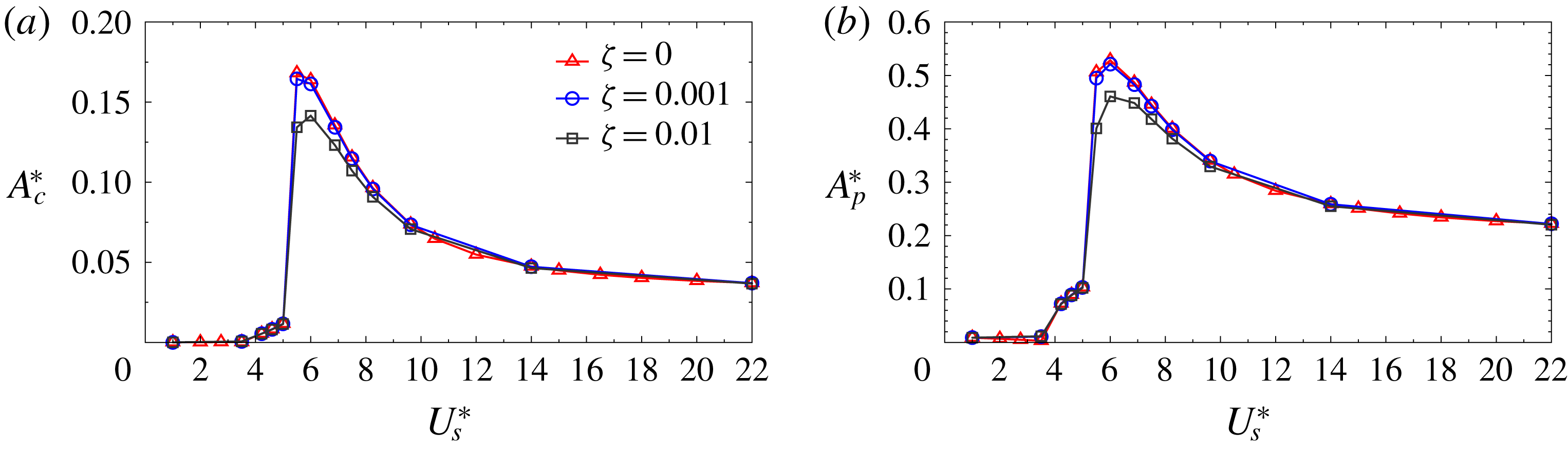
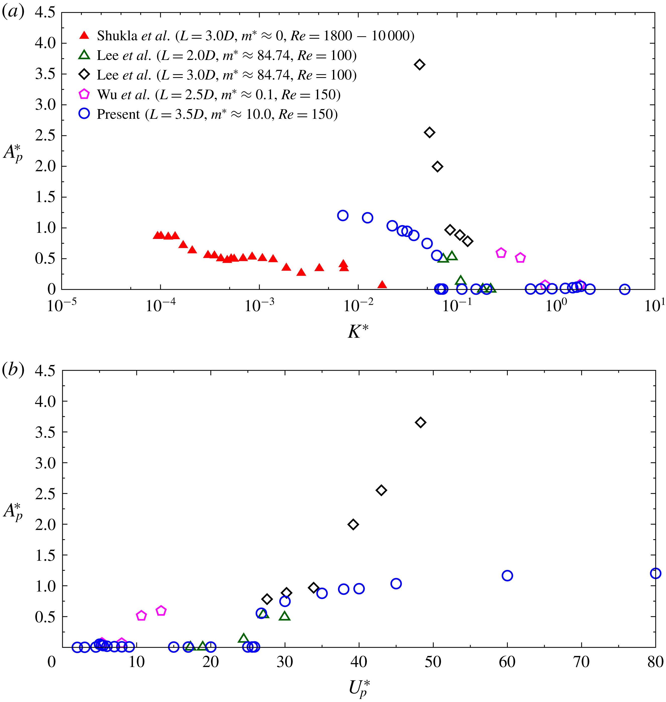
1 Introduction
Bluff body flows are ubiquitous in nature. Extensive studies have been conducted in the past to unravel the underlying physics, and to address the associated engineering applications (Williamson Reference Williamson1996b ). Many of these studies have focused on cylindrical structures. The force exerted by the fluid on the structure in such flows is often unsteady and may lead to flow-induced vibration (FIV) (Anagnostopoulos Reference Anagnostopoulos2002). The FIV is undesirable in several engineering applications. For example, the phenomenon was responsible for the failure of the Tacoma Narrows bridge (Amman, von Kármán & Woodruff Reference Amman, von Kármán and Woodruff1941). However, FIV can also be exploited to be useful such as in applications related to harvesting of energy (Bernitsas et al. Reference Bernitsas, Raghavan, Ben-Simon and Garcia2008, Reference Bernitsas, Ben-Simon, Raghavan and Garcia2009; Soti et al. Reference Soti, Thompson, Sheridan and Bharadwaj2017).
Two types of FIV are of interest in this paper: vortex-induced vibration (VIV) and galloping. We briefly review the two phenomena. Beyond a certain Reynolds number, the wake of a bluff body is associated with vortex shedding. The unsteady forces arising from this shedding may lead to vibration of the body. This is termed as VIV (Bearman Reference Bearman1984, Reference Bearman2011; Sarpkaya Reference Sarpkaya2004; Williamson & Govardhan Reference Williamson and Govardhan2004; Wu, Ge & Hong Reference Wu, Ge and Hong2012). VIV is associated with lock-in/synchronization wherein the vibration frequency of the structure is identical to the vortex-shedding frequency. An important parameter in VIV is
 $m^{\ast }$
, the ratio of the mass of the structure to that of the fluid it displaces. For structures with large
 $m^{\ast }$
the vibration frequency is close to the natural frequency of the structure (
 $f_{n}$
) during lock-in. However, they can be significantly different from
 $f_{n}$
for relatively low
 $m^{\ast }$
, as experimentally observed by Khalak & Williamson (Reference Khalak and Williamson1997, Reference Khalak and Williamson1999). Later, this was numerically verified for low
 $Re$
by Mittal & Kumar (Reference Mittal and Kumar1999) and Sen & Mittal (Reference Sen and Mittal2011). Navrose & Mittal (Reference Mittal2016) investigated lock-in at low
 $Re$
via linear stability analysis of the coupled equations governing the fluid–structure interaction. It was found that the amplitude of the fully developed response of the structure depends on the energy ratio of the unstable eigenmode. Energy ratio is defined as the ratio of the mechanical energy of the spring–mass system to the total energy of the unstable eigenmode. It was shown that much of the growth of amplitude of structural response occurs while the time evolution of the fluid flow is in the linear regime. Kumar & Mittal (Reference Kumar and Mittal2016) studied lock-in via forced oscillations of a cylinder in a uniform flow by carrying out computations for various amplitudes and frequencies of vibration. Lock-in boundary, wherein the shedding frequency latches on to the vibration frequency of the cylinder, was mapped. The results from earlier investigations show significant scatter in identifying lock-in boundary. Kumar & Mittal (Reference Kumar and Mittal2016) showed that the scatter can be attributed to the definition of lock-in utilized by various studies. They proposed a new criterion and showed that it reduces the scatter significantly. They also related the free vibrations to forced vibration by utilizing the energy transfer from the fluid to the structure in each cycle of cylinder oscillation.
Large-amplitude vibrations of the body may also result from galloping instability (Blevins Reference Blevins1990; Anagnostopoulos Reference Anagnostopoulos2002). The force on any structure, of non-circular cross-section, varies with its orientation with respect to the incoming flow. Even if the incident flow is of uniform and constant speed, the lateral oscillation of the body can lead to it experiencing an unsteady inflow in its own frame of reference. Galloping ensues when the unsteady force on the body, due to its lateral movement, causes a further increase in its amplitude of vibration (Blevins Reference Blevins1990).
Regulation of FIV is of great interest in several engineering applications. It can be achieved via control of the unsteadiness of flow. Alternatively, control of the vibration of a structure can also be exploited as a mechanism for flow control (Choi, Jeon & Kim Reference Choi, Jeon and Kim2008). Flow control techniques can be classified into two types, active and passive, based on their energy need other than that in the incoming flow (Gad-el Hak Reference Gad-el Hak1989). Active flow control strategies require external energy input. Some examples of such strategies are control via blowing/suction of boundary layer (Min & Choi Reference Min and Choi1999), steady rotation of the body (Mittal Reference Mittal2001; Mittal & Kumar Reference Mittal and Kumar2003; Navrose & Mittal Reference Navrose and Mittal2015), subjecting it to rotary oscillations (Tokumaru & Dimotakis Reference Tokumaru and Dimotakis1991; Shiels & Leonard Reference Shiels and Leonard2001) and heating of the body (Wan & Patnaik Reference Wan and Patnaik2016). On the other hand, no external energy input is required in passive control. Flow control is achieved by modification of the shape of the body or via use of additional bodies, for example, control cylinder(s) (Mittal & Raghuvanshi Reference Mittal and Raghuvanshi2001) or splitter plate(s) (Roshko Reference Roshko1954, Reference Roshko1955; Law & Jaiman Reference Law and Jaiman2017).
A splitter plate can be utilized to suppress/weaken the vortex shedding from a bluff body. It has also been used in the past for extracting energy from flows (Li & Sun Reference Li and Sun2015; Song et al.
Reference Song, Shan, Lv and Xie2015; Soti et al.
Reference Soti, Thompson, Sheridan and Bharadwaj2017). Roshko (Reference Roshko1954, Reference Roshko1955) carried out some of the earliest experiments for flow past a cylinder with a rigid splitter plate. The
 $Re$
for the study, based on the diameter of the cylinder, was greater than
 $5000$
. Suppression of vortex shedding using a rigid splitter plate has since then been studied experimentally by several other researchers (Apelt, West & Szewczyk Reference Apelt, West and Szewczyk1973; Apelt & West Reference Apelt and West1975; Unal & Rockwell Reference Unal and Rockwell1988; Anderson & Szewczyk Reference Anderson and Szewczyk1997). A rigid splitter plate has also been utilized to suppress VIV (Assi, Bearman & Kitney Reference Assi, Bearman and Kitney2009; Stappenbelt Reference Stappenbelt2010; Assi & Bearman Reference Assi and Bearman2015). In addition, the effect of a rigid plate hinged at the base point of the cylinder (Shukla, Govardhan & Arakeri Reference Shukla, Govardhan and Arakeri2009) as well as that of a flexible plate (Shukla, Govardhan & Arakeri Reference Shukla, Govardhan and Arakeri2013) has been studied. Both periodic and aperiodic oscillations were observed for different plate lengths. All these studies, except the one by Unal & Rockwell (Reference Unal and Rockwell1988), were conducted at
 $Re>1000$
.
There have been several numerical efforts in the past to study suppression of vortex shedding with a rigid splitter plate at low
 $Re$
(Kwon & Choi Reference Kwon and Choi1996; Ozono Reference Ozono1999; Hwang, Yang & Sun Reference Hwang, Yang and Sun2003; Mittal Reference Mittal2003; Bao & Tao Reference Bao and Tao2013). However, there have been relatively few studies on the FIV of a cylinder at low
 $Re$
with a flexible splitter plate. We present a brief review of some of the numerical studies. Lee & You (Reference Lee and You2013) studied the
 $Re=100$
flow past a fixed cylinder with flexible splitter plates of three different lengths. It was shown that the amplitude of VIV was least for the plate of length two times the cylinder diameter. For a highly flexible plate, this length also results in the smallest Strouhal number. However, for an almost rigid plate, Strouhal number monotonically decreases with an increase in plate length. Wu, Shu & Zhao (Reference Wu, Shu and Zhao2014b
) studied the VIV of an elastically supported circular cylinder with a hinged flat plate at
 $Re=150$
. The maximum amplitude of cylinder oscillation and force fluctuations were found to be significantly smaller than those for the VIV of an isolated cylinder. They extended the study to flexible filaments (zero-thickness plates) attached to a fixed as well as an elastically mounted circular cylinder (Wu et al.
Reference Wu, Qiu, Shu and Zhao2014a
). The flexibility and length of the filament were varied. A filament, of certain flexibility and length twice the cylinder diameter, was found to be more effective in weakening the vortex shedding past a fixed cylinder as compared to a rigid plate of the same length. It was also noted that, in certain cases, the mean location of the oscillation of the tip of the filament is away from the centreline. Similar observation was made by Lācis et al. (Reference Lācis, Brosse, Ingremeau, Mazzino, Lundell, Kellay and Bagheri2014) in their experiments using a soap tunnel. For an elastically mounted cylinder, Wu et al. (Reference Wu, Qiu, Shu and Zhao2014a
) identified the range of length of the filament and its flexibility where VIV is suppressed for
 $Re=150$
and certain values of mass ratio and reduced speed. It was found that the minimum length of the filament for suppression of VIV is twice the cylinder diameter.
Furquan & Mittal (Reference Furquan and Mittal2015) numerically investigated flow past two square cylinders, placed side-by-side, with attached flexible splitter plates. The value of
 $Re$
, based on the edge length of the cylinder, was
 $100$
. The plates undergo large-amplitude oscillation when the dominant frequency of vibration is close to the first natural frequency of the plates. This is similar to the well-known phenomenon of lock-in observed in VIV of an isolated cylinder (Singh & Mittal Reference Singh and Mittal2005; Prasanth & Mittal Reference Prasanth and Mittal2008; Prasanth, Premchandran & Mittal Reference Prasanth, Premchandran and Mittal2011; Navrose & Mittal Reference Mittal2016, Reference Mittal2017a
,Reference Mittal
b
). Kundu et al. (Reference Kundu, Soti, Bhardwaj and Thompson2017) studied the response of a flexible splitter plate attached to the base of a circular cylinder for a pulsatile incoming flow at
 $Re=100$
. The plate tip attains maximum amplitude of oscillation when the pulsation frequency is twice the second natural frequency of the plate. The deformed shape of the plate resembles the second eigenmode. They also attributed this observation to lock-in. Using the discrete vortex method, Kawai (Reference Kawai1990) found that a fixed rigid plate placed in the wake of a circular cylinder reduces the VIV significantly. However, oscillations due to galloping occur at higher flow speed. Galloping, at higher reduced flow speeds, has also been observed for a circular cylinder with an attached rigid splitter plate at higher
 $Re$
in several experimental studies (Nakamura, Hirata & Kashima Reference Nakamura, Hirata and Kashima1994; Assi et al.
Reference Assi, Bearman and Kitney2009; Stappenbelt Reference Stappenbelt2010; Assi & Bearman Reference Assi and Bearman2015). Law & Jaiman (Reference Law and Jaiman2017) observed that a C-shaped profile attached to the tip of a rigid splitter plate, at
 $Re=150$
, reduces the amplitude of vibration in VIV and eliminates the galloping instability.
The present work addresses the following questions related to the flow past a circular cylinder with flexible splitter plate at low Reynolds numbers. (i) Most work on lock-in/synchronization has been carried out for a cylinder on an elastic support wherein the system is associated with only one natural frequency. A flexible splitter plate attached to a rigidly mounted cylinder is associated with several natural frequencies/modes. How, then, does the lock-in/synchronization occur in such a scenario? (ii) Further, if the cylinder with a flexible splitter plate is mounted on elastic supports, how do the natural structural frequencies of the system get modified? (iii) What are the response characteristics of this structure? In particular, how does it compare to the free vibration of an isolated cylinder on an elastic support and free vibration of a flexible plate attached to a cylinder on a rigid support? How are the regimes of VIV and galloping affected by the various flow and structural parameters? (iv) How does the flexibility of the plate affect the VIV and galloping response of the structure? Is there an optimal flexibility of the plate that suppresses/minimizes the FIV of the structure? (v) Qualitatively, what is the effect of the length of the splitter plate, the mass ratio and the coefficient of damping of the elastic support?
The present effort is entirely numerical. A stabilized finite element method is utilized. First, the effect of
 $Re$
and plate length (
 $L$
) is studied for flow past a stationary circular cylinder with a rigid splitter plate in the laminar flow regime. The critical
 $Re$
for the onset of vortex shedding for various
 $L$
is determined. For all values of
 $L$
considered, it is found that
 $Re=150$
is large enough for vortex shedding to occur. Next, the effect of flexibility of an attached splitter plate on the FIV of a circular cylinder at
 $Re=150$
is investigated. To better understand the dynamics, the flow past a stationary cylinder with a flexible splitter plate is also studied. The natural frequencies and mode shapes of the flexible plate are obtained using the Euler–Bernoulli beam theory. The variation of the amplitude of the plate tip and its frequency with change in flexibility of the plate is investigated. The deflected shapes and the vibration frequencies of the plate, at various flexibilities, are compared to the corresponding mode shapes and natural frequencies of the plate. Modal analysis is also carried out for the cylinder, mounted on a spring support, with an attached flexible plate. The resulting natural frequencies and the corresponding mode shapes are useful in developing a better understanding of the response of the system. For the elastically mounted cylinder, the amplitude of the cylinder and the plate tip, the phase difference between their displacement and the frequency of vibration are studied for different lengths and flexibilities of the plate. Three regimes of the flow based on the response of the system are identified: VIV, steady flow and galloping. The effect of flexibility of the plate is investigated in the VIV and galloping regimes. Both experimental (Williamson Reference Williamson1996a
) and numerical (Barkley & Henderson Reference Barkley and Henderson1996) investigations show that the flow past a stationary circular cylinder remains two-dimensional up to
 $Re\approx 180$
. Vibration of the cylinder, transverse to the free stream, delays the onset of three-dimensionality to well beyond
 $Re=250$
(Leontini, Thompson & Hourigan Reference Leontini, Thompson and Hourigan2007; Prasanth & Mittal Reference Prasanth and Mittal2008). Laboratory experiments conducted by Gomes et al. (Reference Gomes, Yigit, Lienhart and Schäfer2011) and Gomes & Lienhart (Reference Gomes and Lienhart2013) show that a splitter plate also delays the transition to three-dimensionality to a larger
 $Re$
. Since the present study is restricted to
 $Re=150$
, the flow has been assumed to be two-dimensional.
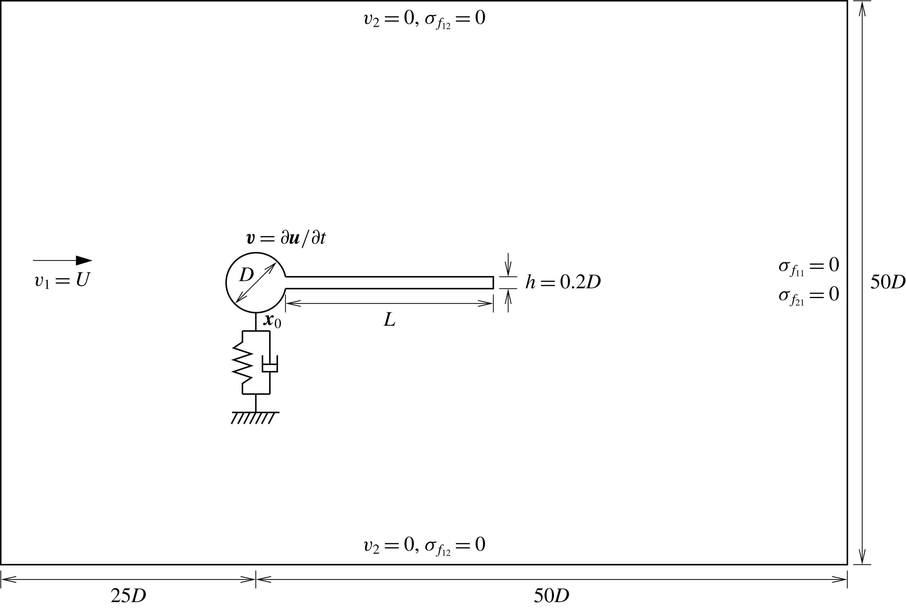
Schematic of the computational set-up (not to scale) for a spring-mounted circular cylinder with flexible splitter plate. Also shown are the boundary conditions.

2 Problem formulation
2.1 Mathematical model
2.1.1 Incompressible flow equations
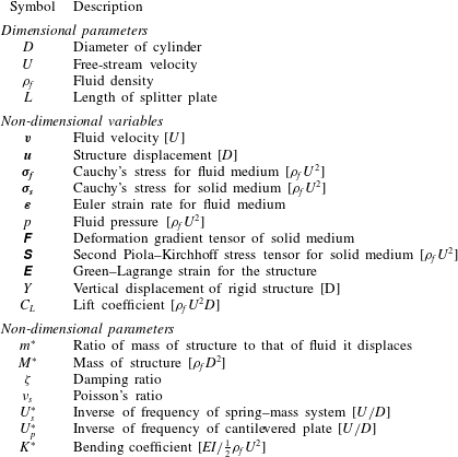
The fluid flow is modelled by the incompressible Navier–Stokes equation along with the continuity constraint defined on an evolving spatial domain
 $\unicode[STIX]{x1D6FA}_{f}(t)$
. The equations, in non-dimensional variables, are
 $$\begin{eqnarray}\displaystyle & \displaystyle \left(\frac{\unicode[STIX]{x2202}\boldsymbol{v}}{\unicode[STIX]{x2202}t}+\boldsymbol{v}\boldsymbol{\cdot }\unicode[STIX]{x1D735}\boldsymbol{v}\right)-\unicode[STIX]{x1D735}\boldsymbol{\cdot }\unicode[STIX]{x1D748}_{\boldsymbol{f}}=\mathbf{0}, & \displaystyle\end{eqnarray}$$
 $$\begin{eqnarray}\displaystyle & \displaystyle \unicode[STIX]{x1D735}\boldsymbol{\cdot }\boldsymbol{v}=0. & \displaystyle\end{eqnarray}$$
Here,
 $\boldsymbol{v}$
and
 $\unicode[STIX]{x1D748}_{\boldsymbol{f}}$
represent the fluid velocity and the Cauchy’s stress tensor, respectively. Length, velocity and time are non-dimensionalized with
 $D$
,
 $U$
and
 $D/U$
, respectively, as also listed in table 1. Cauchy’s stress is non-dimensionalized with
 $\unicode[STIX]{x1D70C}_{f}U^{2}$
, where
 $\unicode[STIX]{x1D70C}_{f}$
is the density of the fluid. Here,
 $D$
is the diameter of the circular cylinder and
 $U$
the free-stream speed of the fluid. For a Newtonian fluid, the constitutive relation that relates
 $\unicode[STIX]{x1D748}_{\boldsymbol{f}}$
to the spatial strain-rate tensor,
 $\unicode[STIX]{x1D750}(\boldsymbol{v})$
, is
 $$\begin{eqnarray}\unicode[STIX]{x1D748}_{\boldsymbol{f}}=-p\unicode[STIX]{x1D644}+\frac{2}{Re}\unicode[STIX]{x1D73A}(\boldsymbol{v}),\end{eqnarray}$$
where
 $p$
and
 $Re$
are the non-dimensional pressure and the Reynolds number of the flow, respectively. Here
 $Re$
is defined as
 $\unicode[STIX]{x1D70C}_{f}UD/\unicode[STIX]{x1D707}$
, where
 $\unicode[STIX]{x1D707}$
is the dynamic viscosity of the fluid. The strain-rate tensor is related to the velocity field as
 $\unicode[STIX]{x1D73A}(\boldsymbol{v})=\frac{1}{2}[\unicode[STIX]{x1D735}\boldsymbol{v}+(\unicode[STIX]{x1D735}\boldsymbol{v})^{\mathsf{T}}]$
. Let
 $\unicode[STIX]{x1D6E4}_{f}(t)$
denote the boundary of the spatial domain
 $\unicode[STIX]{x1D6FA}_{f}(t)$
at any time
 $t$
. The boundary conditions may be of Dirichlet or Neumann type:
 $$\begin{eqnarray}\boldsymbol{v}=\boldsymbol{g}\quad \text{on }\unicode[STIX]{x1D6E4}_{f}^{g}(t)\quad \text{and}\quad \unicode[STIX]{x1D748}_{\boldsymbol{ f}}\boldsymbol{n}=\boldsymbol{h}\quad \text{on }\unicode[STIX]{x1D6E4}_{f}^{h}(t),\end{eqnarray}$$
where
 $\unicode[STIX]{x1D6E4}_{f}^{g}(t)$
and
 $\unicode[STIX]{x1D6E4}_{f}^{h}(t)$
are complementary subsets of the boundary
 $\unicode[STIX]{x1D6E4}_{f}(t)$
and
 $\boldsymbol{n}$
is its unit normal vector. The computational domain along with the boundary conditions is shown in figure 1. The initial condition on the velocity is specified on
 $\unicode[STIX]{x1D6FA}_{f}(t)$
at
 $t=0$
:
 $$\begin{eqnarray}\boldsymbol{v}(\boldsymbol{x},0)=\boldsymbol{v}_{0}(\boldsymbol{x})\quad \text{on }\unicode[STIX]{x1D6FA}_{f}(t=0),\end{eqnarray}$$
where
 $\boldsymbol{v}_{0}$
is divergence free.
Description of some of the key symbols. The scales used for non-dimensionalization of the quantities are placed in square brackets.

2.1.2 Equations governing the elastic structure
A cylindrical structure, of mass per unit span length
 $m$
, is supported by a linear spring at point
 $\boldsymbol{x}_{0}$
that attaches it to a rigid foundation. The damping ratio of the spring–mass system is
 $\unicode[STIX]{x1D701}$
. The deformation of the structure is modelled via the equations for finite elasticity. The equation of motion of the structure, in non-dimensional form, in the total Lagrangian framework is
 $$\begin{eqnarray}m^{\ast }\frac{\text{D}^{2}\boldsymbol{u}}{\text{D}t^{2}}=\unicode[STIX]{x1D735}_{0}\boldsymbol{\cdot }(\unicode[STIX]{x1D641}\unicode[STIX]{x1D64E})+M^{\ast }\left[\left(\frac{2\unicode[STIX]{x03C0}}{U_{s}^{\ast }}\right)^{2}\boldsymbol{u}+\frac{4\unicode[STIX]{x03C0}\unicode[STIX]{x1D701}}{U_{s}^{\ast }}\frac{\text{D}\boldsymbol{u}}{\text{D}t}\right]\unicode[STIX]{x1D6FF}(\boldsymbol{x}-\boldsymbol{x}_{0}).\end{eqnarray}$$
In (2.6),
 $\unicode[STIX]{x1D735}_{0}\boldsymbol{\cdot }(\,)$
denotes the divergence operator in the reference configuration,
 $\unicode[STIX]{x1D6FF}()$
is the Dirac delta function,
 $\boldsymbol{u}$
is the non-dimensional displacement field of the structure, normalized with
 $D$
,
 $M^{\ast }=m/(\unicode[STIX]{x1D70C}_{f}D^{2})$
is the non-dimensional mass of the structure while
 $m^{\ast }$
is the ratio of the density of the structure in its undeformed state to the density of fluid. Here,
 $m^{\ast }$
is also referred to as the mass ratio. For a structure with homogeneous density,
 $m^{\ast }$
corresponds to the ratio of mass of the structure to the mass of the fluid it displaces. The reduced speed is
 $U_{s}^{\ast }=U/f_{n}D$
, where
 $f_{n}$
is the natural frequency of the spring–mass system and
 $D$
the characteristic length;
 $U_{s}^{\ast }$
is the inverse of the non-dimensional natural frequency (
 $F_{ns}$
) of the structure. For the case when the structure is a circular cylinder, we note that
 $m^{\ast }=4/\unicode[STIX]{x03C0}~M^{\ast }$
. In (2.6),
 $\unicode[STIX]{x1D641}$
is the deformation gradient and
 $\unicode[STIX]{x1D64E}$
is the second Piola–Kirchhoff stress tensor, which is related to the Green–Lagrange strain tensor,
 $\unicode[STIX]{x1D640}(\boldsymbol{u})$
, via a constitutive relation. The present study assumes that the material follows the Saint Venant–Kirchhoff constitutive relation:
 $$\begin{eqnarray}\unicode[STIX]{x1D64E}=Ae\left[\frac{\unicode[STIX]{x1D708}_{s}}{(1+\unicode[STIX]{x1D708}_{s})(1-2\unicode[STIX]{x1D708}_{s})}\text{tr}(\unicode[STIX]{x1D640})\unicode[STIX]{x1D644}+\frac{1}{(1+\unicode[STIX]{x1D708}_{s})}\unicode[STIX]{x1D640}\right].\end{eqnarray}$$
Here,
 $\unicode[STIX]{x1D708}_{s}$
and
 $Ae$
represent the Poisson’s ratio and the elasticity of the material;
 $Ae$
is defined as
 $E/\unicode[STIX]{x1D70C}_{f}U^{2}$
, where
 $E$
is the Young’s modulus.
Also, considered in the present study is the FIV of a rigid structure mounted on a linear spring, and allowed to translate only in the vertical direction. In this situation, equation (2.6), which governs the motion of the structure, simplifies to the following:
 $$\begin{eqnarray}\ddot{Y} +\frac{4\unicode[STIX]{x03C0}\unicode[STIX]{x1D701}}{U_{s}^{\ast }}{\dot{Y}}+\left(\frac{2\unicode[STIX]{x03C0}}{U_{s}^{\ast }}\right)^{2}Y=\frac{C_{L}(t)}{2M^{\ast }}.\end{eqnarray}$$
This equation represents the motion of a spring–mass oscillator. Here,
 $Y$
is the normalized vertical displacement of the structure.
2.1.3 Boundary conditions at the fluid–structure interface
The velocity and traction fields are continuous across the interface of the fluid and structure,
 $\unicode[STIX]{x1D6E4}_{fs}$
:
 $$\begin{eqnarray}\frac{\unicode[STIX]{x2202}\boldsymbol{u}}{\unicode[STIX]{x2202}t}=\boldsymbol{v}\quad \text{and}\quad \unicode[STIX]{x1D748}_{\boldsymbol{s}}\boldsymbol{n}=\unicode[STIX]{x1D748}_{\boldsymbol{f}}\boldsymbol{n}\quad \text{on }\unicode[STIX]{x1D6E4}_{fs}.\end{eqnarray}$$
Here,
 $\unicode[STIX]{x1D748}_{\boldsymbol{s}}$
and
 $\unicode[STIX]{x1D748}_{\boldsymbol{f}}$
denote the Cauchy’s stress tensor for the structure and fluid, respectively, and
 $\boldsymbol{n}$
is a vector normal to the interface.
2.2 Computational approach
2.2.1 Finite element formulations
The deforming-spatial-domain/stabilized space–time (DSD/SST) method (Tezduyar, Behr & Liou Reference Tezduyar, Behr and Liou1992a ; Tezduyar et al. Reference Tezduyar, Behr, Mittal and Liou1992c ; Mittal Reference Mittal2000; Tezduyar Reference Tezduyar2003) is utilized to solve the equations governing the flow. This method is also applicable to a temporally evolving spatial domain. The stabilizations are based on the streamline-upwind/Petrov–Galerkin (Brooks & Hughes Reference Brooks and Hughes1982) and pressure-stabilizing/Petrov–Galerkin (Tezduyar et al. Reference Tezduyar, Mittal, Ray and Shih1992d ) approaches.
Calculix (Dhondt & Wittig Reference Dhondt and Wittig1998; Dhondt Reference Dhondt2004), an open-source program, is used for simulating the dynamics of the structure. It utilizes the Galerkin method to solve equation (2.6) and accounts for geometric nonlinearity. A two-noded spring element is deployed to model the point support to the structure via a linear spring. In the implementation, a rigid structure is modelled by applying appropriate kinematic constraints, while solving equation (2.6). The semi-discrete equations are integrated in time by the modified Newmark scheme (Dhondt Reference Dhondt2004).
2.2.2 Fluid–structure coupling and mesh moving scheme
A partitioned method based on block-iterative coupling, similar to that presented in Kalro & Tezduyar (Reference Kalro and Tezduyar2000) and Bazilevs, Takizawa & Tezduyar (Reference Bazilevs, Takizawa and Tezduyar2013), is utilized for solving the coupled fluid–structure problem. The flow solver provides the loads that act on the structure at its interface with the fluid. The response of the structure to these loads, computed from the structure solver, alters the velocity and the shape of the interface, to be conformed by the fluid. The fluid flow and structural analyses are carried out alternately until convergence is achieved at each time step. Each of the fluid solver and structure solver is based on an implicit method.
The finite element mesh for the flow problem is updated to conform to the new spatial domain as the structure deforms. A mesh moving scheme, that models the domain as a linear elastic pseudo-solid, is utilized (Tezduyar et al. Reference Tezduyar, Behr, Mittal and Johnson1992b , Reference Tezduyar, Aliabadi, Behr, Johnson and Mittal1993; Johnson & Tezduyar Reference Johnson and Tezduyar1994). This scheme enables avoiding/minimizing remeshing, and the associated projection errors. The nodes are simply relocated without changing the topology of the initial grid. This also enables an efficient parallelization of the computations. The displacement of the structure is used as a boundary condition at the fluid–structure interface and the governing equations of linear elasticity are solved to determine the displacement of the other nodes of the finite element mesh for the flow problem. To minimize the distortion of the mesh, the stiffness is assumed to be inversely proportional to the volume of each element. The implementation of the scheme is the same as for the flow past two square cylinders, in side-by-side arrangement, with flexible splitter plates (Furquan & Mittal Reference Furquan and Mittal2015).
2.2.3 Validation of the method
The DSD/SST method has been applied to a variety of fluid–structure interaction problems in the past (e.g. Bazilevs et al.
Reference Bazilevs, Takizawa and Tezduyar2013). In the present work, the flow solver based on the DSD/SST method is coupled with Calculix, an open-source program for solving structural dynamics (Dhondt & Wittig Reference Dhondt and Wittig1998). The same was utilized in one of our earlier studies (Furquan & Mittal Reference Furquan and Mittal2015). The study also presented a validation of the implementation of the coupling between the solvers via solution to a benchmark problem (Turek & Hron Reference Turek and Hron2006). The test case involves flow past a rigid circular cylinder, of diameter
 $D$
, with an attached flexible splitter plate of length
 $3.5D$
and thickness
 $0.2D$
, placed inside a channel. The self-excited oscillations of the fluid–structure system are considered. No-slip condition on the velocity is applied at the channel walls. A parabolic velocity profile is specified at the inflow. The cylinder and splitter plate assembly is located slightly away from the centreline of the channel. The Reynolds number, based on
 $D$
and the average speed at the inflow, is
 $100$
. The other parameters are
 $m^{\ast }=10$
,
 $\unicode[STIX]{x1D708}_{s}=0.4$
and
 $Ae=1400$
. The results from the present implementation are found to be in good agreement with those from Turek & Hron (Reference Turek and Hron2006). The implementation was utilized to study the flow past two square cylinders, in side-by-side arrangement, with flexible splitter plates (Furquan & Mittal Reference Furquan and Mittal2015).
The various configurations of cylinder and splitter plate studied in this work.

2.3 Problem description
Flow-induced vibration of a rigid circular cylinder with a flexible splitter plate, mounted on an elastic support, is investigated. A schematic of the set-up is shown in figure 1. Three values of plate length are considered:
 $L=1.5D$
,
 $2.5D$
and
 $3.5D$
, where
 $D$
is the diameter of the cylinder. The thickness of the plate is
 $h=0.2D$
. The value of
 $Re$
, based on the free-stream speed and
 $D$
, is
 $150$
. The mass and damping ratios for the structure are
 $m^{\ast }=10$
and
 $\unicode[STIX]{x1D701}=0$
, unless stated otherwise. We note that
 $\unicode[STIX]{x1D701}=0$
encourages a high amplitude of vibration. The spring is permitted to deform only in the vertical direction, thereby restricting the vibration of the cylinder to
 $y$
- only. Computations are carried out for various values of the reduced speeds:
 $U_{s}^{\ast }$
and
 $U_{p}^{\ast }$
which characterize the stiffness of the spring support and the flexible splitter plate. The study involves combinations of the cylinder, an attached splitter plate and an elastic support that attaches the cylinder to a fixed foundation. The notation to identify these combinations is listed in table 2. Here
 ${\mathcal{C}}$
denotes the cylinder and
 ${\mathcal{P}}$
the splitter plate. The subscripts
 $stat$
and
 $vib$
refer to the stationary and vibrating states, respectively. A stationary cylinder is denoted using
 ${\mathcal{C}}_{stat}$
, while a freely vibrating one, i.e. a cylinder mounted on spring support, is denoted by
 ${\mathcal{C}}_{vib}$
. Similarly,
 ${\mathcal{P}}_{stat}$
and
 ${\mathcal{P}}_{vib}$
represent a stationary/rigid and flexible/vibrating splitter plate. The configuration corresponding to a rigid splitter plate attached to a freely vibrating cylinder is denoted by
 ${\mathcal{C}}_{vib}{\mathcal{P}}_{stat}$
.
2.3.1 The non-dimensional parameters
The natural frequency of the spring–mass system, for the case either with no plate (
 ${\mathcal{C}}_{vib}$
) or when the plate is rigid (
 ${\mathcal{C}}_{vib}{\mathcal{P}}_{stat}$
), is denoted by
 $f_{ns}$
. The flexible splitter plate is a continuous system, and is therefore associated with infinite natural frequencies. Let
 $f_{np}^{k}$
denote the natural frequency corresponding to the
 $k\text{th}$
eigenmode of the system
 ${\mathcal{C}}_{stat}{\mathcal{P}}_{vib}$
. Similarly, let
 $f_{nsp}^{k}$
denote the natural frequency corresponding to the
 $k\text{th}$
eigenmode of the combined system of the cylinder on spring and flexible plate
 ${\mathcal{C}}_{vib}{\mathcal{P}}_{vib}$
. The normalized natural frequency of the structure, non-dimensionalized with
 $U/D$
, in the respective cases is
 $F_{ns}$
,
 $F_{np}^{k}$
and
 $F_{nsp}^{k}$
. The subscripts
 $n$
,
 $s$
and
 $p$
refer to natural frequency, spring and plate, respectively. The reduced speed is defined as the inverse of the normalized natural frequency for
 $k=1$
. In particular, the reduced speeds based on the natural frequency for the spring–mass and for the flexible splitter plate without the spring are extensively utilized in this work to present the results. They are defined as
 $U_{s}^{\ast }=1/F_{ns}$
and
 $U_{p}^{\ast }=1/F_{np}^{1}$
.
Overall, the present model of fluid–structure interaction can be described via five non-dimensional parameters. One possible combination is: Reynolds number (
 $Re$
), reduced speed of the spring–mass oscillator (
 $U_{s}^{\ast }$
), reduced speed of the flexible structure (
 $U_{p}^{\ast }$
), mass ratio (
 $m^{\ast }$
) and Poisson’s ratio of the material (
 $\unicode[STIX]{x1D708}_{s}$
).
2.3.2 Computational domain, boundary and initial conditions
The circular cylinder with a flexible splitter plate is placed in a rectangular domain. The upstream and downstream boundaries are located at a distance of
 $25D$
and
 $50D$
from the centre of the cylinder, respectively. The lateral boundaries are separated by a distance of
 $H=50D$
; the blockage,
 $B=D/H$
, is
 $2\,\%$
. The boundary conditions are shown in figure 1. Uniform flow is specified at the inflow boundary. The velocity on the fluid–solid interface satisfies the no-slip condition; the velocity of the structure is identical to that of the fluid. The normal component of the velocity and tangential component of the stress vector are prescribed zero value on the lateral boundaries. The stress vector, on the outflow boundary, is set to a zero value. Most computations have been initiated from the fully developed unsteady flow past a stationary cylinder with rigid splitter plate. The exceptions to this initial condition are the computations to investigate the hysteresis due to increasing and decreasing
 $U_{p}^{\ast }$
, and presented in § 3.4. The details of the initial conditions for those computations are described therein.
2.3.3 The finite element mesh and mesh convergence
A three-dimensional implementation of the finite element formulation is utilized to carry out the computations. Two layers of a two-dimensional mesh, with linear triangles, are stacked along the span to result in a grid with six-noded wedge elements. This set-up is equivalent to carrying out two-dimensional computations. The flow domain, for cylinder with splitter plate of length
 $L=3.5D$
, is discretized using
 $54\,536$
elements. Equal-in-order interpolation functions are employed for velocity and pressure. We refer to this mesh as
 $M1$
. To ascertain the adequacy of the mesh, the results of the computations on this mesh are compared to those on a finer mesh,
 $M2$
. Mesh
 $M2$
consists of approximately twice the number of elements in
 $M1$
. The details of the two meshes are listed in table 3. The test case considered is of the type
 ${\mathcal{C}}_{vib}{\mathcal{P}}_{vib}$
. Twenty-noded brick elements are utilized for the structural analysis of the flexible plate. A two-noded linear spring element is included, to provide elastic support, between a node on the cylinder and an external fixed node. Table 3 lists the normalized amplitude of vibration of the cylinder (
 $A_{c}^{\ast }$
) and the tip of the flexible plate (
 $A_{p}^{\ast }$
), the coefficient of fluid force on the structure and normalized frequency of vibration of the structure (
 $F$
) for the limit-cycle oscillations corresponding to
 $U_{s}^{\ast }=6$
,
 $U_{p}^{\ast }=12.8$
and
 $L=3.5D$
. These values of reduced speed are used for the convergence test as they result in close-to-highest amplitude of cylinder and plate tip oscillation in the VIV regime. The results from the two meshes, and with a time step size of
 $\unicode[STIX]{x0394}t=0.025$
, are listed in rows
 $1$
and
 $3$
of the table. They are in excellent agreement; the largest deviation between the two sets of results is for the fluctuating component of the cylinder displacement (
 ${\sim}2.1\,\%$
). Therefore, mesh
 $M1$
is used for all computations in this work. The effect of time step size is also studied. The results for
 $\unicode[STIX]{x0394}t=0.025$
and
 $0.0125$
with mesh
 $M1$
are listed in rows
 $1$
and
 $2$
of the table. Again, the two sets of results are in very good agreement. The maximum difference is in the oscillation amplitude of the cylinder and is approximately
 $2.4\,\%$
. Since this is in the acceptable range,
 $\unicode[STIX]{x0394}t=0.025$
is used for all the calculations in this paper.
Flow past a spring-mounted circular cylinder with flexible splitter plate for
 $Re=150$
,
 $m^{\ast }=10$
,
 $U_{s}^{\ast }=6$
,
 $U_{p}^{\ast }=12.8$
,
 $L=3.5D$
and
 $B=2\,\%$
: effect of mesh resolution and time step size (
 $\unicode[STIX]{x0394}t$
).

3 Results
3.1 Modal analysis of the structure
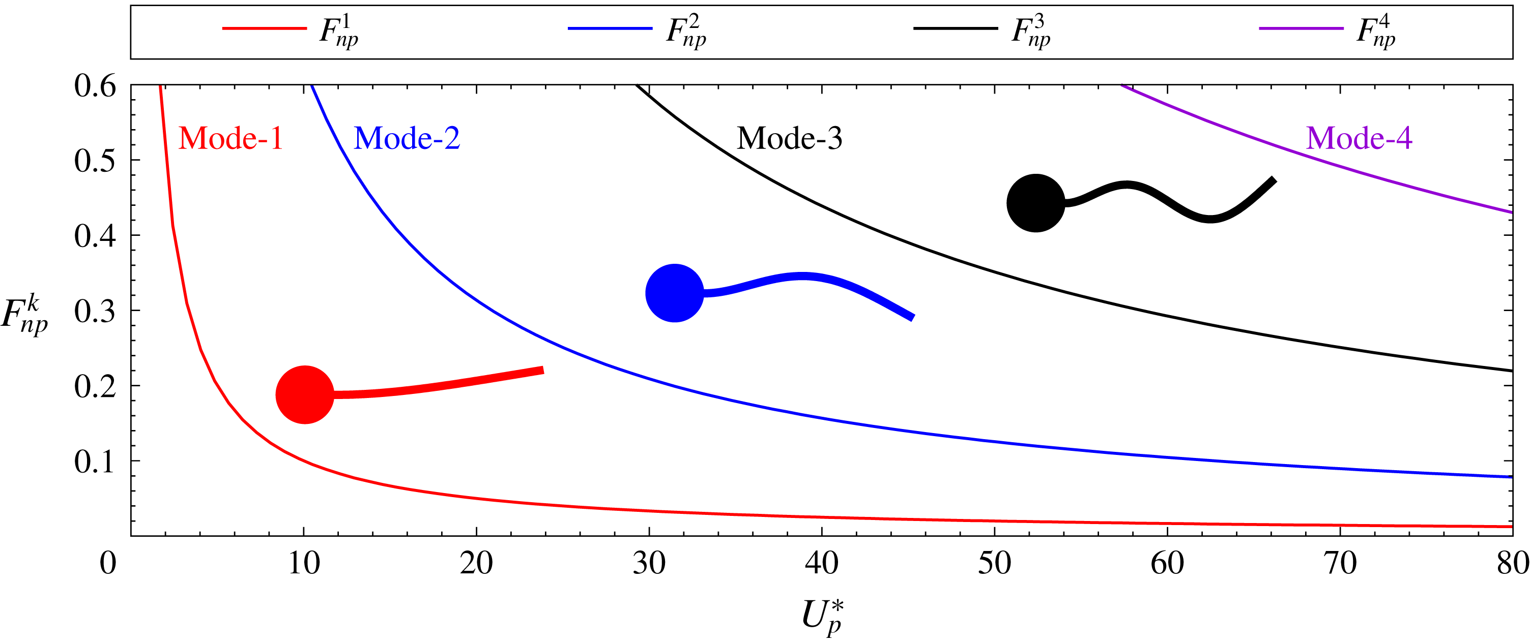
3.1.1 Stationary cylinder with a flexible splitter plate (
 ${\mathcal{C}}_{stat}{\mathcal{P}}_{vib}$
)

Free vibration of a flexible splitter plate attached to a fixed cylinder (
 ${\mathcal{C}}_{stat}{\mathcal{P}}_{vib}$
): variation of non-dimensionalized natural frequencies,
 $F_{np}^{k}$
, with reduced velocity,
 $U_{p}^{\ast }$
, for the first four modes of vibration. The corresponding mode shapes of the plate are shown for
 $L=3.5D$
.

The natural frequency of the flexible splitter plate is estimated for defining
 $U_{p}^{\ast }$
. Each plate, of certain flexibility, is associated with infinite natural frequencies and eigenmodes. It is modelled as a cantilever beam and the first few modes are estimated using the Euler–Bernoulli beam theory. We utilize the natural frequency of the first mode of the plate, thus obtained, to characterize its flexibility. To this extent, the reduced velocity of the plate is defined as
 $U_{p}^{\ast }=1/F_{np}^{1}=(6.191(L/D)^{2}/(h/D))\sqrt{m^{\ast }/Ae}$
. The details of the estimation are in appendix A. We note that
 $U_{p}^{\ast }=0$
corresponds to a rigid plate. The value of
 $U_{p}^{\ast }$
increases with an increase in flexibility of the plate. Figure 2 shows the variation of
 $F_{np}^{k}$
with
 $U_{p}^{\ast }$
for the first four eigenmodes. The natural frequency of vibration for each mode varies inversely with variation in
 $U_{p}^{\ast }$
. The characteristic mode shape associated with each of the first three natural frequencies is also shown in the figure.
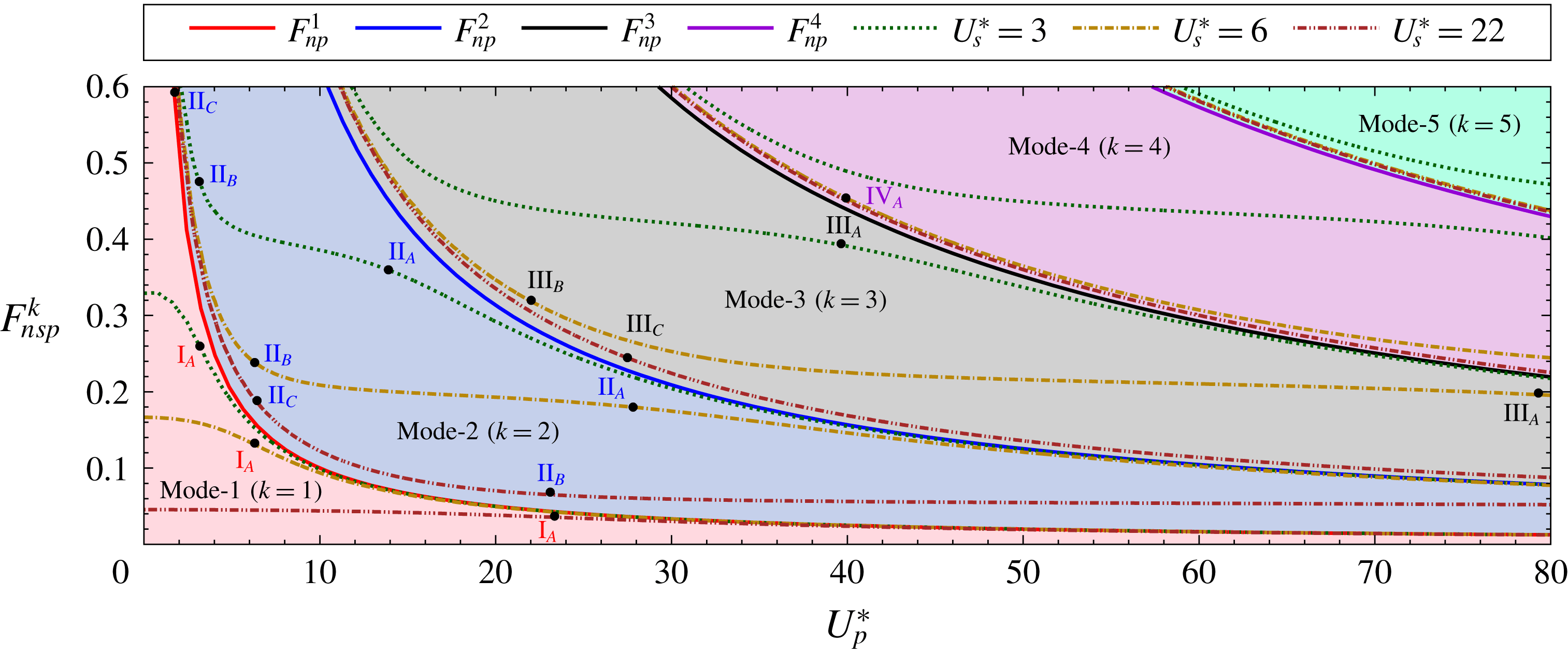
Free vibration of an elastically supported circular cylinder with flexible plate (
 ${\mathcal{C}}_{vib}{\mathcal{P}}_{vib}$
): variation of non-dimensionalized natural frequency,
 $F_{nsp}^{k}$
, with the reduced velocity,
 $U_{p}^{\ast }$
, for various values of
 $U_{s}^{\ast }$
. The natural frequencies associated with different eigenmodes lie in non-overlapping regions, shown with different shades. These regions are bounded by the
 $F_{np}^{k}$
versus
 $U_{p}^{\ast }$
curves, drawn with solid lines, which are also shown in figure 2.

3.1.2 Elastically supported cylinder with a flexible splitter plate (
${\mathcal{C}}_{vib}{\mathcal{P}}_{vib}$
)

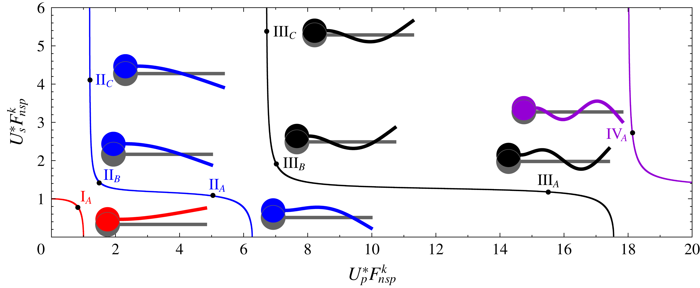
The system can undergo combined heave oscillations of spring–mass and bending vibrations of the plate. The compliance of the splitter plate and elastic support is characterized by the reduced speeds
 $U_{p}^{\ast }$
and
 $U_{s}^{\ast }$
, respectively. Figure 3 shows the variation of the first five natural frequencies of the system (
 $F_{nsp}^{k}$
,
 $k=1,2,\ldots ,5$
) with
 $U_{p}^{\ast }$
and
 $U_{s}^{\ast }$
. We note that the system
 ${\mathcal{C}}_{vib}{\mathcal{P}}_{vib}$
degenerates to
 ${\mathcal{C}}_{stat}{\mathcal{P}}_{vib}$
, i.e. a rigid support, for
 $U_{s}^{\ast }=0$
. Consequently, the curve corresponding to
 $F_{nsp}^{k}$
, shown in solid line for
 $U_{s}^{\ast }=0$
in figure 3, is identical to the curve for
 $F_{np}^{k}$
in figure 2 for all
 $k$
. It is seen from figure 3 that each mode occupies a distinct region in the
 $F_{nsp}^{k}$
–
 $U_{p}^{\ast }$
plane. It can be shown (see appendix A) that each region can be collapsed into a curve by using the similarity variables
 $U_{s}^{\ast }F_{nsp}^{k}$
and
 $U_{p}^{\ast }F_{nsp}^{k}$
. This is shown in figure 4 along with mode shapes for a few points on these curves. The figure is useful in understanding as to how the addition of the heave degree of freedom to
 ${\mathcal{C}}_{stat}{\mathcal{P}}_{vib}$
, in terms of the elastic support, modifies the eigenmodes/values of the system
 ${\mathcal{C}}_{vib}{\mathcal{P}}_{vib}$
. We make the following four observations. (i) The cylinder and plate tip move in phase for the odd-numbered modes and out of phase for the even-numbered ones. (ii) The first mode of
 ${\mathcal{C}}_{vib}{\mathcal{P}}_{vib}$
is similar to that for
 ${\mathcal{C}}_{stat}{\mathcal{P}}_{vib}$
. (iii) For
 $k>1$
,
 $F_{nsp}^{k}$
as well as the shape of the plate in the
 $k\text{th}$
eigenmode of
 ${\mathcal{C}}_{vib}{\mathcal{P}}_{vib}$
are, respectively, close to
 $F_{np}^{k-1}$
and the
 $(k-1)\text{th}$
eigenmode of
 ${\mathcal{C}}_{stat}{\mathcal{P}}_{vib}$
for large values of
 $U_{s}^{\ast }$
and fixed
 $U_{p}^{\ast }$
. For small
 $U_{s}^{\ast }$
, they are close to the
 $F_{np}^{k}$
and the
 $k\text{th}$
eigenmode of
 ${\mathcal{C}}_{stat}{\mathcal{P}}_{vib}$
. (iv) As a consequence of observation (iii), we see from figure 4 that both
 $F_{nsp}^{k}$
and
 $F_{nsp}^{k+1}$
can be close to
 $F_{np}^{k}$
, for suitable values of
 $U_{p}^{\ast }$
and
 $U_{s}^{\ast }$
. In either case, the shape of the deformed plate is similar to that in the
 $k\text{th}$
mode of
 ${\mathcal{C}}_{stat}{\mathcal{P}}_{vib}$
. However, the plate tip is in phase with the cylinder in one case and out of phase in the other.
Free vibration of an elastically supported circular cylinder with flexible splitter plate (
 ${\mathcal{C}}_{vib}{\mathcal{P}}_{vib}$
): figure 3 that shows variation of natural frequency with
 $U_{p}^{\ast }$
and
 $U_{s}^{\ast }$
is re-plotted in terms of similarity variables
 $U_{s}^{\ast }F_{nsp}^{k}$
and
 $U_{p}^{\ast }F_{nsp}^{k}$
. Curves I, II, III and IV, shown in different colours, correspond to first four natural frequencies. Also shown are the different mode shapes for
 $L=3.5D$
.

3.2 Flow past a stationary circular cylinder (
${\mathcal{C}}_{stat}$
) and with an attached rigid splitter plate (
${\mathcal{C}}_{stat}{\mathcal{P}}_{stat}$
)


Uniform flow past an isolated cylinder, and that with an attached rigid splitter plate is studied. It is well known that the splitter plate reduces/suppresses the vortex shedding (Roshko Reference Roshko1954, Reference Roshko1955; Apelt et al.
Reference Apelt, West and Szewczyk1973; Apelt & West Reference Apelt and West1975; Unal & Rockwell Reference Unal and Rockwell1988; Kwon & Choi Reference Kwon and Choi1996; Anderson & Szewczyk Reference Anderson and Szewczyk1997; Ozono Reference Ozono1999; Hwang et al.
Reference Hwang, Yang and Sun2003; Mittal Reference Mittal2003; Bao & Tao Reference Bao and Tao2013). The minimum length of a rigid splitter plate, attached to the cylinder, that suppresses the vortex shedding increases with an increase in
 $Re$
(Kwon & Choi Reference Kwon and Choi1996). Conversely, the critical
 $Re$
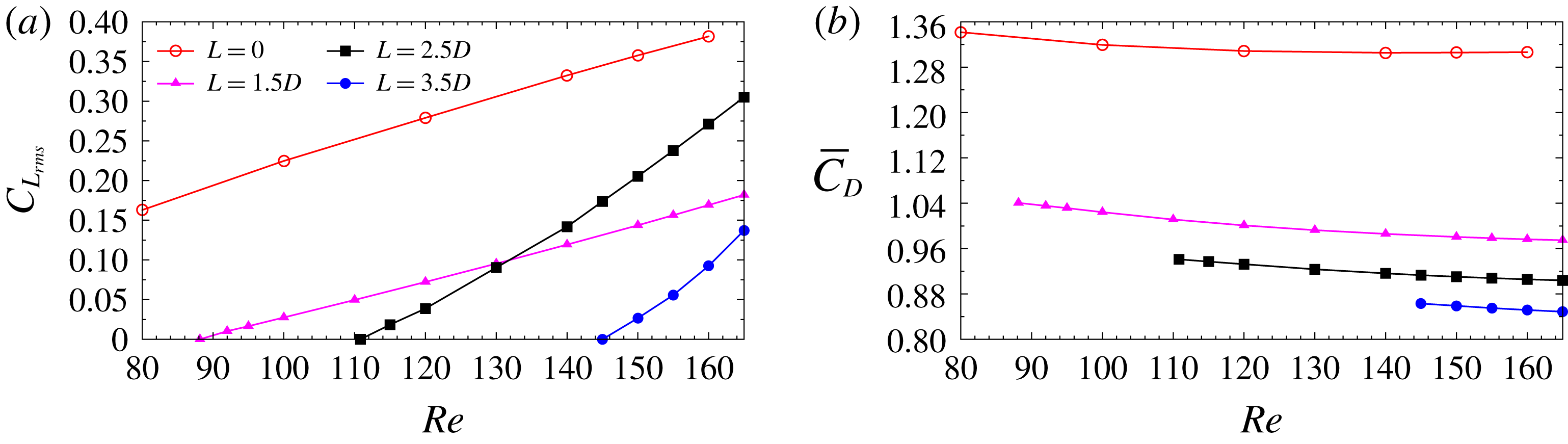
for the onset of unsteadiness increases with an increase in the length of the splitter plate. Figure 5(a) shows the variation of the root-mean-square value of lift coefficient with
 $Re$
for three different plate lengths:
 $L=1.5D$
,
 $2.5D$
and
 $3.5D$
. Plates of these lengths completely suppress vortex shedding for
 $Re<88$
,
 $111$
and
 $145$
, respectively. The critical
 $Re$
is estimated in the following manner. For
 $Re$
close to the onset of unsteadiness, computations are carried out for various
 $Re$
. These computations are initiated from the steady solution at the respective
 $Re$
. The steady flow is computed by dropping the unsteady terms from the governing equations. The time history of the lift coefficient, in the linear regime, is utilized to estimate the growth rate. The critical
 $Re$
is estimated from the growth rate at various
 $Re$
. Even though the flow is unsteady beyond critical
 $Re$
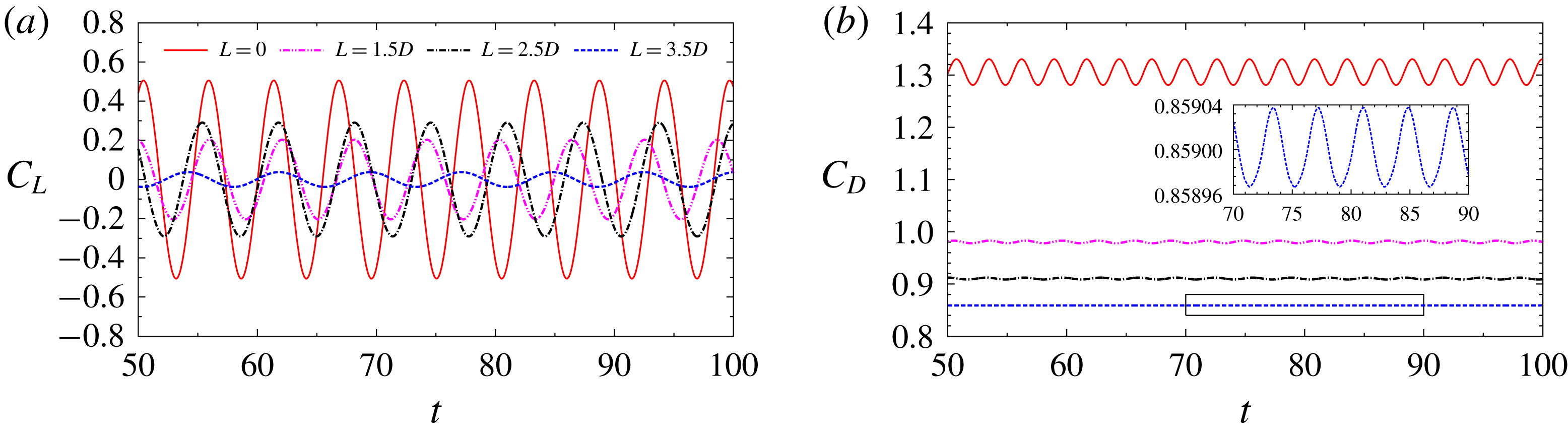
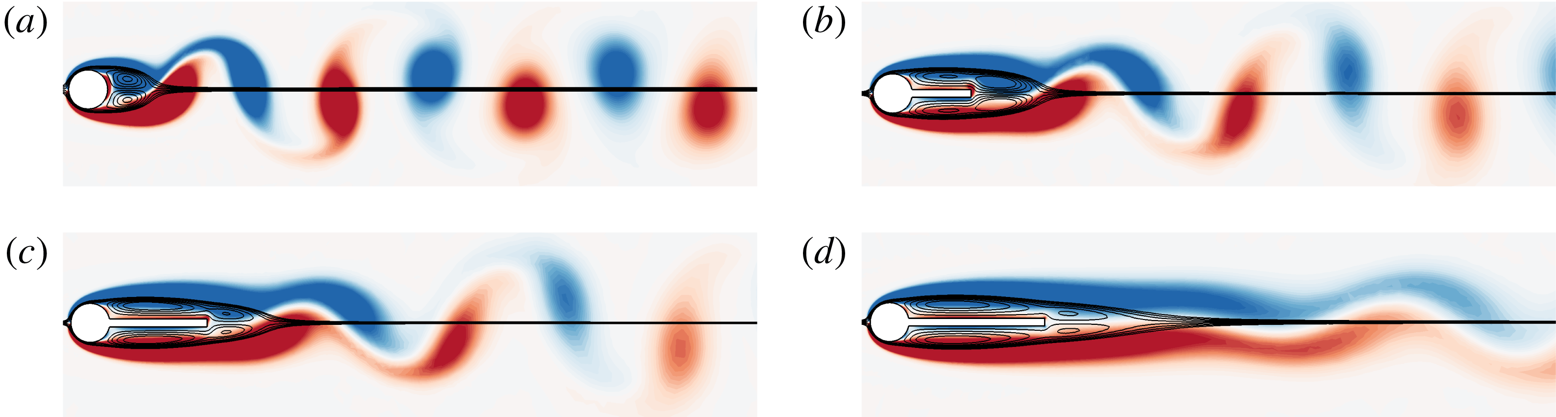
, the unsteadiness is significantly lower as compared to the flow without the plate. This is seen from figures 6 and 7 that show the time variation of the force coefficients and the unsteady vorticity field at
 $Re=150$
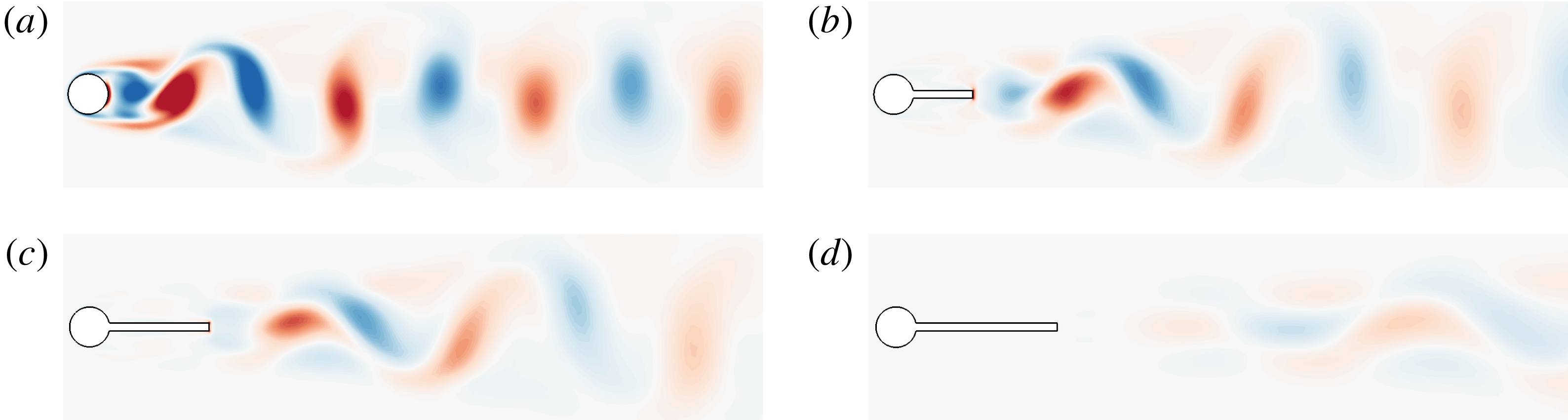
for an isolated cylinder and for a cylinder with splitter plate of different lengths. There is a very significant reduction in the amplitude of time variation of force coefficients (figure 6). It is observed from figure 7(d) that for a plate of length
 $3.5D$
the near wake is almost steady, while very weak shedding, at a lower frequency, is observed in the far wake. Figure 5(b) shows that the splitter plate also reduces the mean drag coefficient by a significant amount. The reduction in drag is mostly due to the reduction in Reynolds stress. A relatively smaller contribution to reduction in the drag is also due to the increase in the recirculation zone, as seen from the time-averaged streamlines (see figure 7), which leads to negative contribution from the skin friction on the splitter plate.
Flow past a stationary cylinder with rigid splitter plate of length
 $L$
(
 ${\mathcal{C}}_{stat}{\mathcal{P}}_{stat}$
): variation of (a) root mean square of the lift coefficient,
 $C_{L_{rms}}$
, and (b) time-averaged drag coefficient,
 $\bar{C}_{D}$
, with
 $Re$
. The data points are shown for only those
 $Re$
for which the flow is unsteady.

The
 $Re=150$
flow past a stationary cylinder (
 ${\mathcal{C}}_{stat}$
) and with an attached rigid splitter plate of length
 $L$
(
 ${\mathcal{C}}_{stat}{\mathcal{P}}_{stat}$
): time variation of (a) lift and (b) drag coefficient. Here
 $L=0$
corresponds to the
 ${\mathcal{C}}_{stat}$
case.

The
 $Re=150$
flow past a stationary cylinder (
 ${\mathcal{C}}_{stat}$
) and with an attached rigid splitter plate (
 ${\mathcal{C}}_{stat}{\mathcal{P}}_{stat}$
): vorticity field for (a) an isolated cylinder (
 $L=0$
); and a cylinder with a rigid plate of length (b)
 $L=1.5D$
, (c)
 $L=2.5D$
and (d)
 $L=3.5D$
. All panels correspond to a time instant when the
 $C_{L}$
is at its peak value for the fully developed unsteady flow. Also shown are the time-averaged streamlines.

The
 $Re=150$
flow past a stationary cylinder (
 ${\mathcal{C}}_{stat}$
) and with an attached rigid splitter plate (
 ${\mathcal{C}}_{stat}{\mathcal{P}}_{stat}$
): fluctuation in vorticity field for (a) an isolated cylinder (
 $L=0$
); and a cylinder with a rigid plate of length (b)
 $L=1.5D$
, (c)
 $L=2.5D$
and (d)
 $L=3.5D$
. All panels correspond to a time instant when the
 $C_{L}$
is at its peak value for the fully developed unsteady flow.

An interesting observation from figure 5(a) is that beyond
 $Re\sim 130$
a longer plate (
 $L=2.5D$
) results in larger fluctuations in
 $C_{L}$
as compared to a shorter one (
 $L=1.5D$
). This is also seen from the time histories of
 $C_{L}$
shown in figure 6(a). To study this further, we consider the effect of
 $L$
at
 $Re=150$
. We note that
 $C_{L}$
has a contribution from the surface of the cylinder as well as the plate. There are two effects at play. The contribution of the plate to the lift can potentially increase, with an increase in the length of the plate. However, the increase in the length of the plate can also affect the unsteadiness of the flow, as seen from the fluctuation in vorticity field for different plate lengths shown in figure 8. Therefore, it is quite likely that a certain plate length is optimal for maximizing the amplitude of
 $C_{L}$
. Also, the secondary vortices present at the plate tip are close to the cylinder for
 $L=1.5D$
. These vortices counteract to reduce the force induced by the primary vortices (You et al.
Reference You, Choi, Choi and Kang1998).
3.3 Vortex-induced vibration of a circular cylinder (
${\mathcal{C}}_{vib}$
)

The
 $Re=150$
flow past a freely vibrating cylinder (
 ${\mathcal{C}}_{vib}$
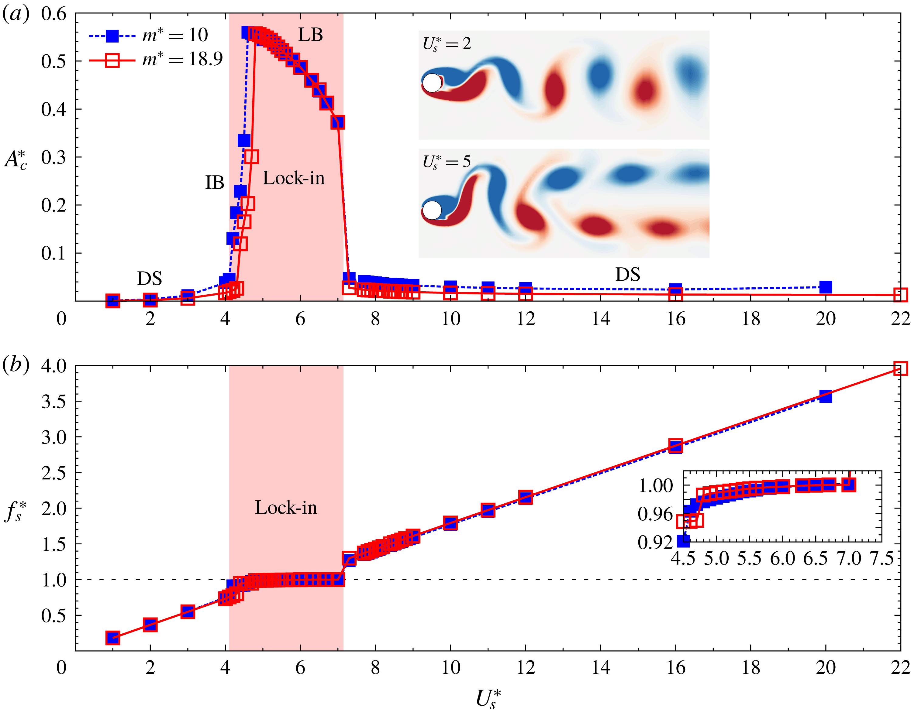
): variation of (a) non-dimensionalized amplitude of cylinder displacement
 $A_{c}^{\ast }$
and (b) frequency ratio
 $f_{s}^{\ast }$
with reduced velocity
 $U_{s}^{\ast }$
. Here
 $f_{s}^{\ast }$
is the ratio of the cylinder vibration frequency (
 $f_{v}$
) to the natural frequency of the spring–mass system (
 $f_{ns}$
). The lock-in regime is shaded in coral. Also marked are the desynchronization region (DS), initial branch (IB) and lower branch (LB). The insets in (a) show the instantaneous vorticity field for the fully developed unsteady flow for DS (
 $U_{s}^{\ast }=2$
) and LB (
 $U_{s}^{\ast }=5$
).

Free vibration of an isolated circular cylinder on an elastic mount is studied for two values of mass ratio:
 $m^{\ast }=10$
and
 $18.9$
. The variation of amplitude and frequency response of the system with
 $U_{s}^{\ast }$
is shown in figure 9. The VIV at
 $Re=150$
, for both
 $m^{\ast }=10$
and
 $18.9$
, is qualitatively similar to the well-studied
 $Re=100$
and
 $m^{\ast }=10$
case (Navrose & Mittal Reference Mittal2017a
). The computations for
 $m^{\ast }=18.9$
are useful in comparing the free vibration of an isolated cylinder and that with a rigid splitter plate. Although the density ratio of the solid to the fluid is
 $10.0$
, the extra mass accounts for the additional inertia of the splitter plate attached to the cylinder. No significant difference is observed in the response of the cylinder for
 $m^{\ast }=10$
and
 $m^{\ast }=18.9$
. The response of the system can be classified into various regimes: desynchronization (DS), initial branch (IB) and lower branch (LB) (Singh & Mittal Reference Singh and Mittal2005). The large-amplitude response of the system is associated with synchronization/lock-in, wherein the vortex shedding frequency is identical to the vibration frequency of the system. The IB and LB lie in the region of lock-in (figure 9). In this range of reduced speed (
 $U_{s}^{\ast }$
) the vibration frequency is very close to the natural frequency of the structure. In the DS regime, the vortex shedding frequency of the freely vibrating cylinder is close to the shedding frequency for the flow past a stationary cylinder.
3.4 Vortex-induced vibration of a stationary cylinder with flexible splitter plate (
${\mathcal{C}}_{stat}{\mathcal{P}}_{vib}$
)

The
 $Re=150$
flow past a fixed cylinder with a flexible splitter plate (
 ${\mathcal{C}}_{stat}{\mathcal{P}}_{vib}$
) with
 $L=3.5D$
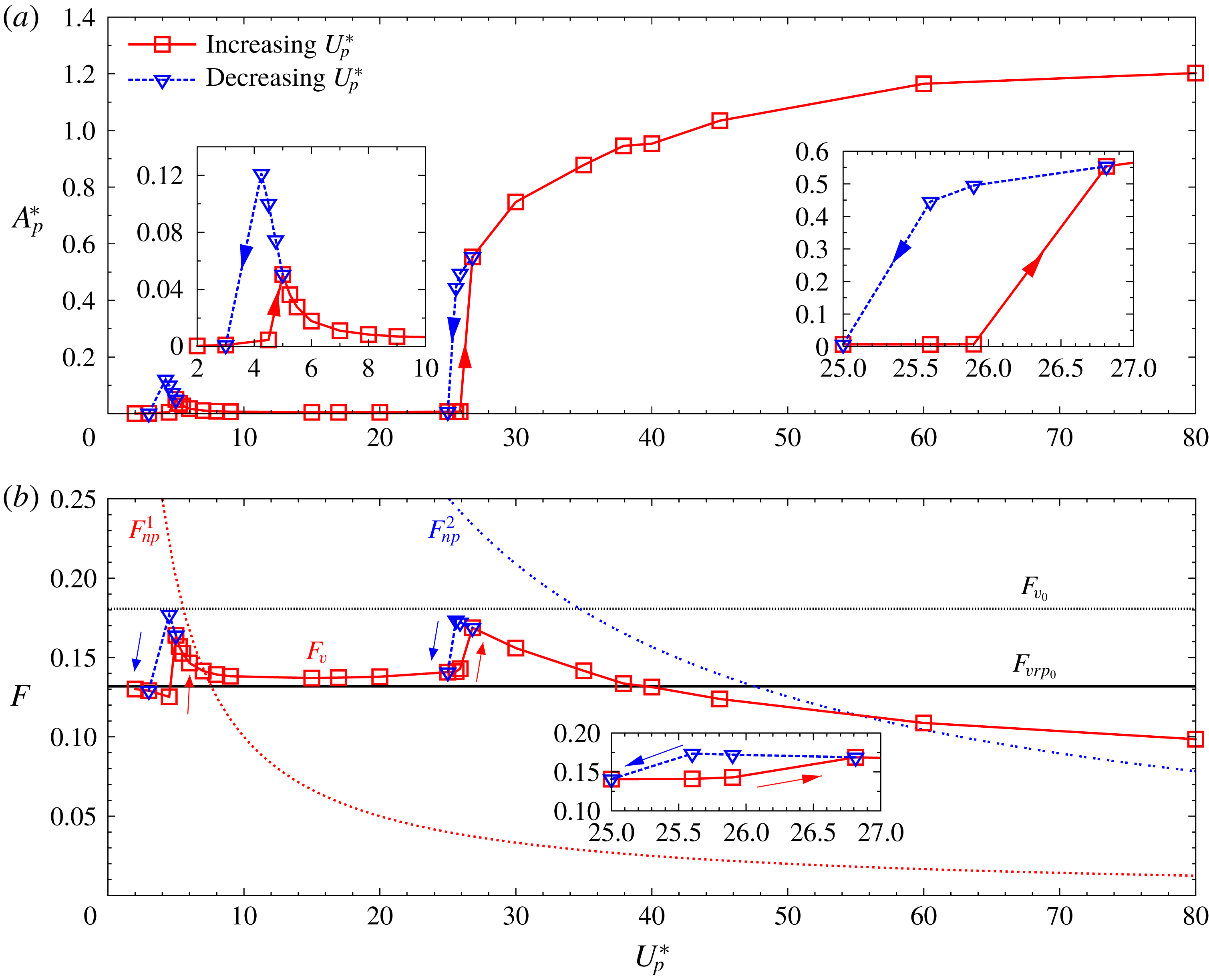
: variation of non-dimensionalized (a) amplitude
 $A_{p}^{\ast }$
and (b) frequency
 $F_{v}$
of the plate-tip displacement with reduced speed
 $U_{p}^{\ast }$
. Also shown for reference are the non-dimensional vortex shedding frequency for a stationary cylinder with rigid splitter plate,
 $F_{vrp_{0}}$
, and fixed cylinder without splitter plate,
 $F_{v_{0}}$
.

The
 $Re=150$
flow past a fixed cylinder with flexible splitter plate (
 ${\mathcal{C}}_{stat}{\mathcal{P}}_{vib}$
) with
 $L=3.5D$
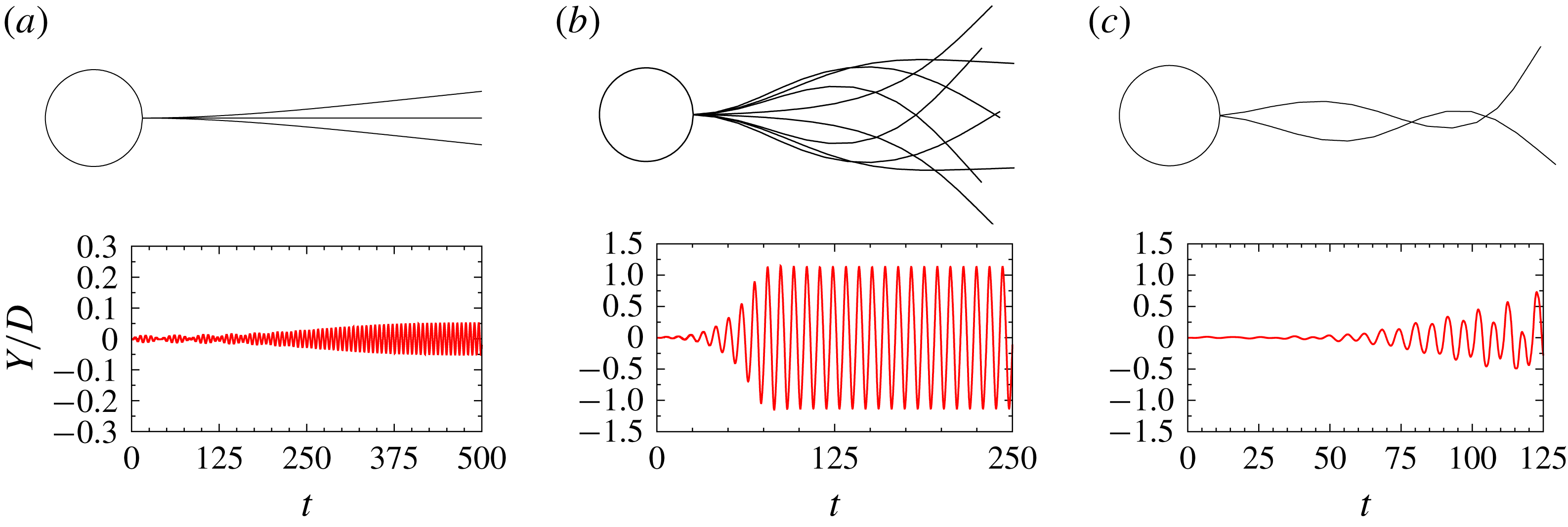
: shape of the flexible splitter plate at various time instants in one cycle of oscillation (top) and the corresponding time history of plate-tip displacement (bottom) for (a)
 $U_{p}^{\ast }=5$
, (b)
 $U_{p}^{\ast }=60$
and (c)
 $U_{p}^{\ast }=100$
. For
 $U_{p}^{\ast }=5$
, the deflection of the plate is amplified by a factor of five for clarity. Images for
 $U_{p}^{\ast }=100$
do not correspond to a fully developed limit cycle, but during the time when the flow is still developing.

The
 $Re=150$
flow past a fixed cylinder with flexible splitter plate (
 ${\mathcal{C}}_{stat}{\mathcal{P}}_{vib}$
) with
 $L=3.5D$
: dominant proper orthogonal decomposition modes for (a)
 $U_{p}^{\ast }=5$
, (b)
 $U_{p}^{\ast }=60$
and (c)
 $U_{p}^{\ast }=100$
. The numerals indicate ranking of the modes in decreasing order of their energy content.

The
 $Re=150$
flow past a fixed cylinder with flexible splitter plate (
 ${\mathcal{C}}_{stat}{\mathcal{P}}_{vib}$
) with
 $L=3.5D$
: instantaneous vorticity field for (a)
 $U_{p}^{\ast }=5$
, (b)
 $U_{p}^{\ast }=60$
and (c)
 $U_{p}^{\ast }=100$
at an instant when the displacement of the plate tip is at its maximum value. The image for
 $U_{p}^{\ast }=100$
does not correspond to a fully developed limit cycle, but during the time when the flow is still developing.

Figure 10 shows the amplitude and frequency of the tip response of the plate of length
 $3.5D$
for various reduced speeds,
 $U_{p}^{\ast }$
. In all cases
 $m^{\ast }$
is
 $10$
and
 $Re=150$
. The plate vibrates with relatively low amplitude for
 $U_{p}^{\ast }<25$
. Beyond this value, large-amplitude oscillations are observed. A local peak in the response amplitude is seen in figure 10(a) at
 $U_{p}^{\ast }\sim 5$
. Figure 10(b) shows that in this region, the vibration frequency of the plate is close to the natural frequency of its first mode of vibration. For other values of
 $U_{p}^{\ast }$
, less than
 $25$
, the frequency of plate-tip vibration is close to the vortex shedding frequency for a fixed cylinder with a rigid plate. Beyond
 $U_{p}^{\ast }\sim 25$
, the vibration frequency of the plate is closer to the natural frequency of its second mode of vibration. Figure 11 shows the centreline of the splitter plate at various time instants for three values of
 $U_{p}^{\ast }$
. The figure also shows time histories of the tip displacement for the three cases. The proper orthogonal decomposition modes of the flexible plate, which account for about 90 % of its energy content related to the deformation of the plate, corresponding to the fully developed response at the same values of
 $U_{p}^{\ast }$
are shown in figure 12. The shapes of the various proper orthogonal decomposition modes are remarkably close to those of the Euler–Bernoulli modes. While the plate exhibits the first Euler–Bernoulli mode of vibration for
 $U_{p}^{\ast }=5$
, it undergoes a combination of the first and second modes for
 $U_{p}^{\ast }=60$
. For
 $U_{p}^{\ast }=100$
, the plate appears to undergo predominantly the third mode of vibration.
Figure 13 shows the instantaneous vorticity field for these three values of
 $U_{p}^{\ast }$
. Compared to a stationary cylinder with rigid splitter plate (figure 7
d) the flow for flexible splitter plate for
 $U_{p}^{\ast }=5$
(figure 13
a) is associated with stronger vortices and higher frequency (figure 10
b) leading to a reduced spacing between the vortices in the wake. The flow at
 $U_{p}^{\ast }=60$
(figures 10
b and 13
b) is associated with even stronger vortices and lower vortex shedding frequency. A relatively complex vortex shedding pattern is observed for
 $U_{p}^{\ast }=100$
(figure 13
c). Figure 10 shows jumps in the response of the plate at the onset of lock-in regions, i.e. at
 $U_{p}^{\ast }\sim$
 $3$
and
 $25$
. The jumps are hysteretic in the sense that computations with increasing and decreasing
 $U_{p}^{\ast }$
lead to different responses. We describe the procedure for obtaining the hysteretic response at the second jump. The same process is utilized to track the other hysteretic responses. For increasing
 $U_{p}^{\ast }$
, computations are first carried out for
 $U_{p}^{\ast }=25$
. The fully developed unsteady flow is used as an initial condition for the incremented
 $U_{p}^{\ast }$
. The fully developed unsteady flow for this
 $U_{p}^{\ast }$
is then used an an initial condition for the next incremented value of
 $U_{p}^{\ast }$
and so on. Similarly, for decreasing
 $U_{p}^{\ast }$
, the computations begin with the fully developed unsteady solution for
 $U_{p}^{\ast }=30$
as an initial condition for the case of a decremented
 $U_{p}^{\ast }$
. In the region of hysteresis, the state of decreasing
 $U_{p}^{\ast }$
is associated with a relatively large-amplitude response, while that of increasing
 $U_{p}^{\ast }$
is associated with a low-amplitude response. As seen from figure 10(b), the vibration frequency of the plate for the low-amplitude response is close to the vortex shedding frequency past a stationary cylinder with rigid splitter plate. On the other hand, the vibration frequency is closer to the natural frequency of the second mode when the response amplitude is large. As has been done for the free vibration of an isolated cylinder on elastic supports, one can identify the lock-in for this case as well. It consists of two regimes for the range of
 $U_{p}^{\ast }$
considered in this study. The first one is
 $3\leqslant U_{p}^{\ast }\leqslant 10$
, approximately, and the second one is
 $U_{p}^{\ast }>25$
.
3.5 Flow past an elastically supported circular cylinder with rigid splitter plate (
${\mathcal{C}}_{vib}{\mathcal{P}}_{stat}$
)

The
 $Re=150$
flow past a spring-mounted circular cylinder, with (
 ${\mathcal{C}}_{vib}{\mathcal{P}}_{stat}$
) and without (
 ${\mathcal{C}}_{vib}$
) a rigid splitter plate: variation of (a) normalized amplitude of cylinder displacement
 $A_{c}^{\ast }$
and (b) frequency ratio
 $f_{s}^{\ast }$
with reduced velocity
 $U_{s}^{\ast }$
. Three plate lengths are considered. The various regimes of response for
 $L=3.5D$
are marked with different shades: VIV (yellow), steady (grey) and galloping (coral).

The
 $Re=150$
flow past a spring mounted circular cylinder with a rigid splitter plate (
 ${\mathcal{C}}_{vib}{\mathcal{P}}_{stat}$
): the instantaneous vorticity field for
 $L=3.5D$
and (a)
 $U_{s}^{\ast }=6$
, (b)
 $U_{s}^{\ast }=12$
, (c)
 $U_{s}^{\ast }=22$
and (d)
 $L=1.5D$
and
 $U_{s}^{\ast }=22$
, when the cylinder displacement is maximum.

Recently, Sahu et al. (Reference Sahu, Furquan, Jaiswal and Mittal2019) studied the FIV of a circular cylinder with rigid plate (
 ${\mathcal{C}}_{vib}{\mathcal{P}}_{stat}$
system) at
 $Re=150$
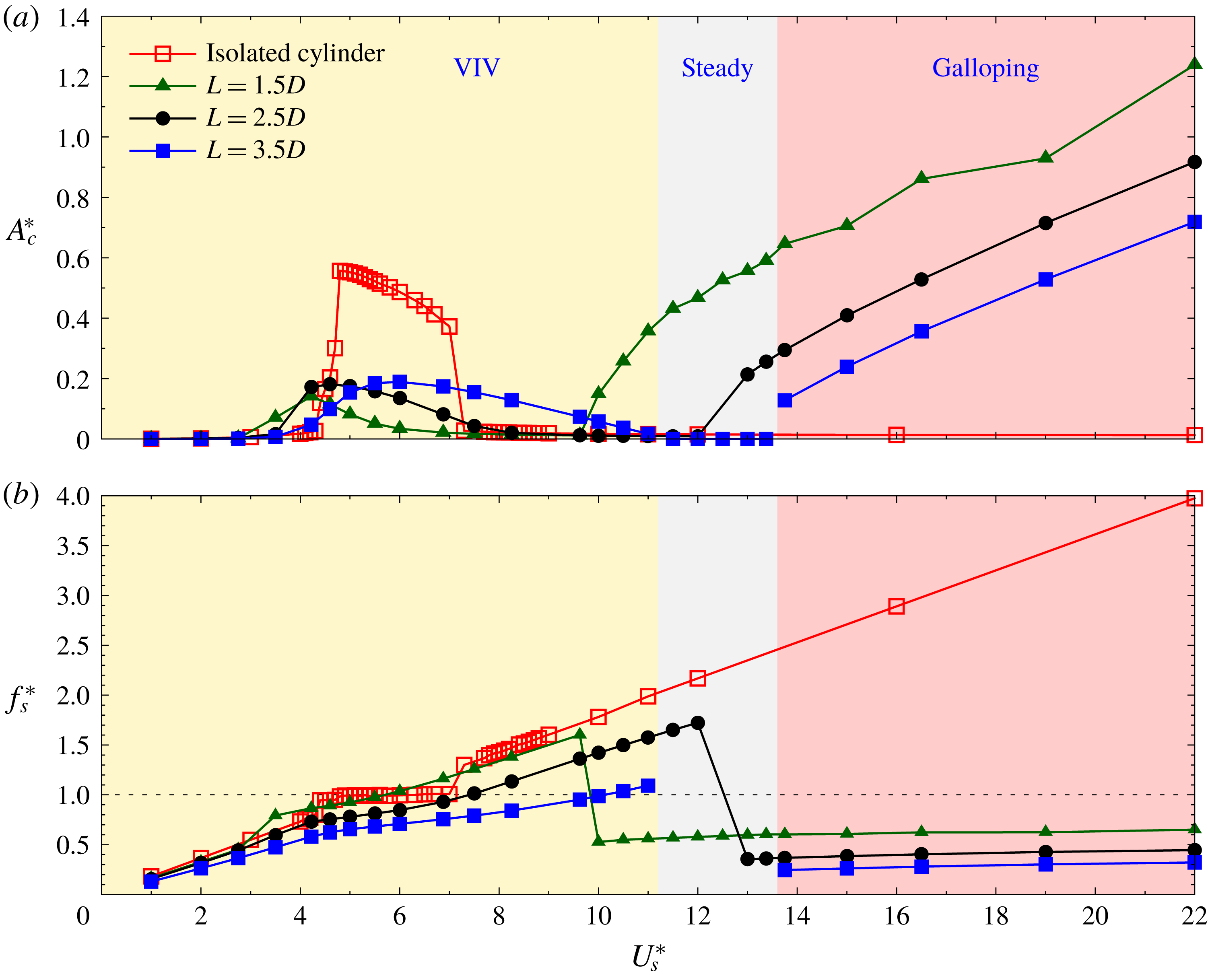
for a wide range of mass ratios. Figure 14(a) shows a comparison between the amplitude response of the cylinder with an attached rigid splitter plate at
 $m^{\ast }=10$
(Sahu et al.
Reference Sahu, Furquan, Jaiswal and Mittal2019) and that of an isolated cylinder at
 $m^{\ast }=18.9$
. The comparison of the frequencies of cylinder vibration, normalized with their respective natural frequencies, is shown in figure 14(b). Three plate lengths are considered:
 $L=1.5D$
,
 $2.5D$
and
 $3.5D$
. The case of
 $m^{\ast }=18.9$
is useful in determining if the observed differences are caused by the changes in the flow due to the splitter plate or its additional inertia compared to the isolated cylinder. More details of this are in § 3.3. As seen from figure 14, the splitter plate has a significant effect on the free vibrations. Sahu et al. (Reference Sahu, Furquan, Jaiswal and Mittal2019) broadly classified the response, with splitter plate, into three regimes in terms of the reduced speed: VIV, steady flow and galloping. They are briefly described below. The regions are also marked in figure 14, based on the response of the case with
 $L=3.5D$
.
(i) Vortex-induced vibration. Unlike for an isolated cylinder, the variation of amplitude and frequency of cylinder response with
$U_{s}^{\ast }$
does not show any jump/sharp changes. The maximum amplitude of response is also significantly smaller than that for an isolated cylinder. The maximum amplitude during VIV response is nearly the same for different values of plate length. However, the range of the lock-in regime increases with an increase in
$L$
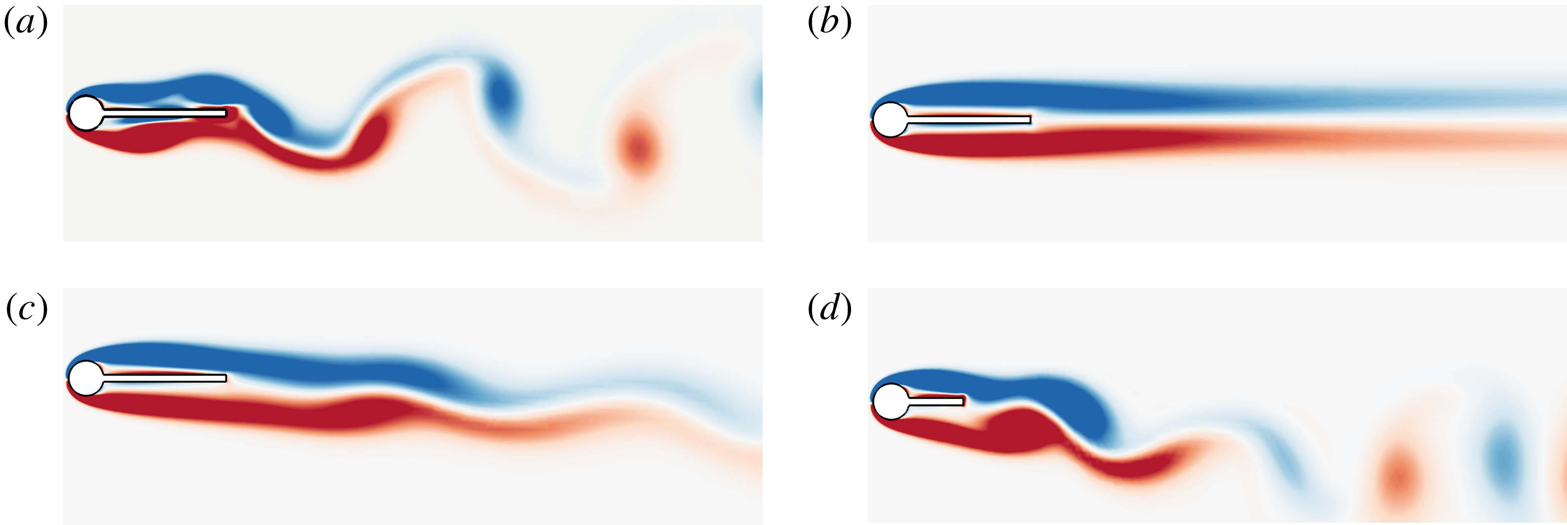
. Figure 15(a) shows a typical instantaneous vorticity field for the VIV of a circular cylinder with rigid splitter plate. The case shown corresponds to
$L=3.5D$
and
$U_{s}^{\ast }=6$
, for which the amplitude of oscillation is close to maximum. The time instant chosen is the one when the structure is at its maximum
$y$
-location for the fully developed unsteady flow.(ii) Steady flow. For a plate length of
$3.5D$
, vortex shedding is completely suppressed for
$11<U_{s}^{\ast }\leqslant 13.37$
. We recall that the flow past a cylinder with attached splitter plate is unsteady at this
$Re$
when the system is mounted on a rigid support. However, the elastic support renders stability to the fluid–structure system. This is akin to ‘amplitude death’ observed in certain situations for two or more coupled autonomously vibrating systems (Aronson, Ermentrout & Kopell Reference Aronson, Ermentrout and Kopell1990). Figure 15(b) shows the vorticity of the flow field for
$U_{s}^{\ast }=12$
. Interestingly, the steady regime is not observed for
$L=1.5D$
and
$2.5D$
.(iii) Galloping. Galloping oscillations are observed for relatively high
$U_{s}^{\ast }$
for all plate lengths considered. The critical
$U_{s}^{\ast }$
for onset of galloping depends on the length of the rigid splitter plate. Figure 15(c) shows the vorticity field for
$U_{s}^{\ast }=22$
and
$L=3.5D$
at a time instant when the structure is at its maximum transverse location for the fully developed unsteady flow and cylinder vibration. The vortex shedding is weak and occurs far downstream in wake, away from the cylinder. The near wake is virtually quiescent. The vibration frequency of the structure is significantly lower than its natural frequency and remains nearly constant with variation in
$U_{s}^{\ast }$
. Figure 14(a) shows that the amplitude of galloping oscillations increases almost linearly with an increase in
$U_{s}^{\ast }$
. This is consistent with earlier findings that characterize galloping (Blevins Reference Blevins1990). Unlike for longer plates, there is significant vortex shedding activity in the near wake for shorter splitter plates (
$L=1.5D$
and
$2.5D$
) during galloping. Figure 15(d) shows the vorticity field for
$U_{s}^{\ast }=22$
and
$L=1.5D$
. Compared to the case of
$L=3.5D$
, and the same
$U_{s}^{\ast }$
(Figure 15
c), the vortex shedding in the near wake is much stronger. This behaviour has also been observed in the past and has been referred to as VIV–galloping interaction (Mannini, Marra & Bartoli Reference Mannini, Marra and Bartoli2014; Liang, Wang & Hu Reference Liang, Wang and Hu2018). The variation of amplitude with
$U_{s}^{\ast }$
, shown in figure 14(a), deviates significantly from the almost linear trend observed for pure galloping. The frequency of vibration remains constant with
$U_{s}^{\ast }$
, as in the case of pure galloping, but has a higher value (figure 14
b).


3.6 Flow past an elastically supported circular cylinder with a flexible splitter plate (
${\mathcal{C}}_{vib}{\mathcal{P}}_{vib}$
)

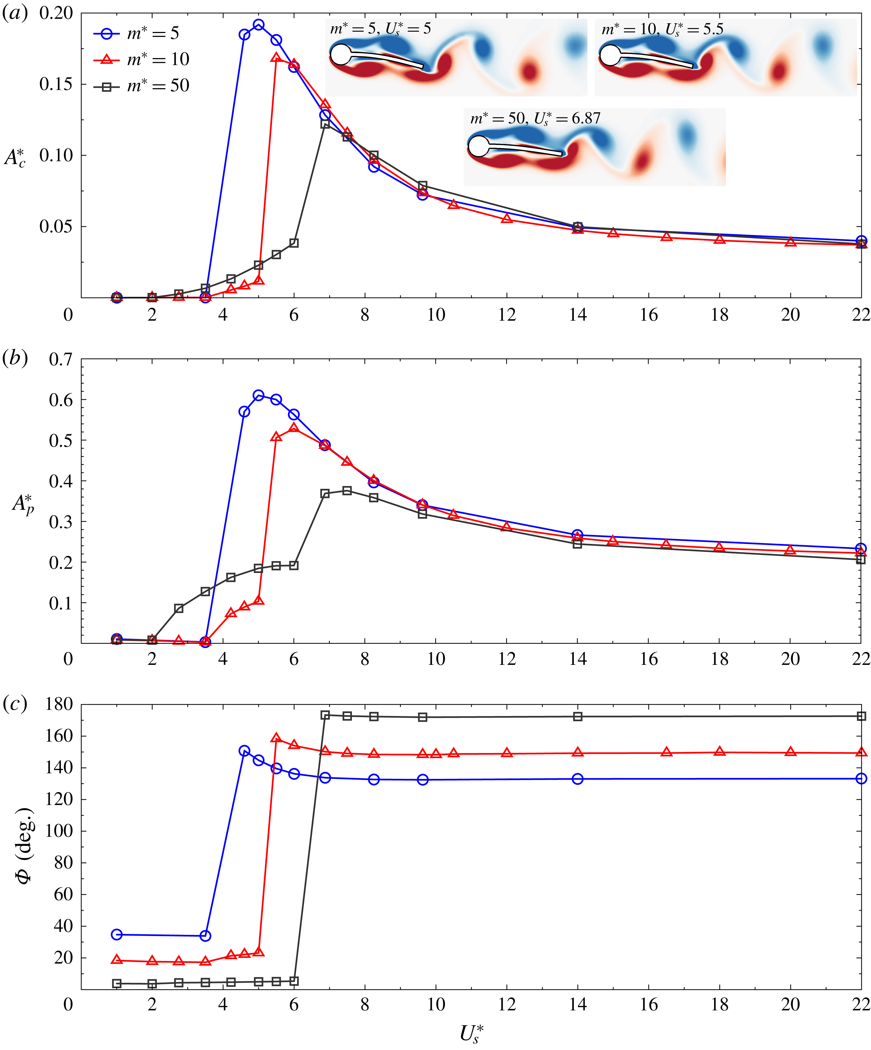
The
 $Re=150$
,
 $L=3.5D$
flow past a spring-mounted circular cylinder with a flexible splitter plate (
 ${\mathcal{C}}_{vib}{\mathcal{P}}_{vib}$
): variation of the normalized amplitude of (a) cylinder oscillation
 $A_{c}^{\ast }$
and (b) plate tip vibration
 $A_{p}^{\ast }$
with reduced velocity
 $U_{s}^{\ast }$
. (c) The phase,
 $\unicode[STIX]{x1D6F7}$
, between the vibration of cylinder and plate tip.

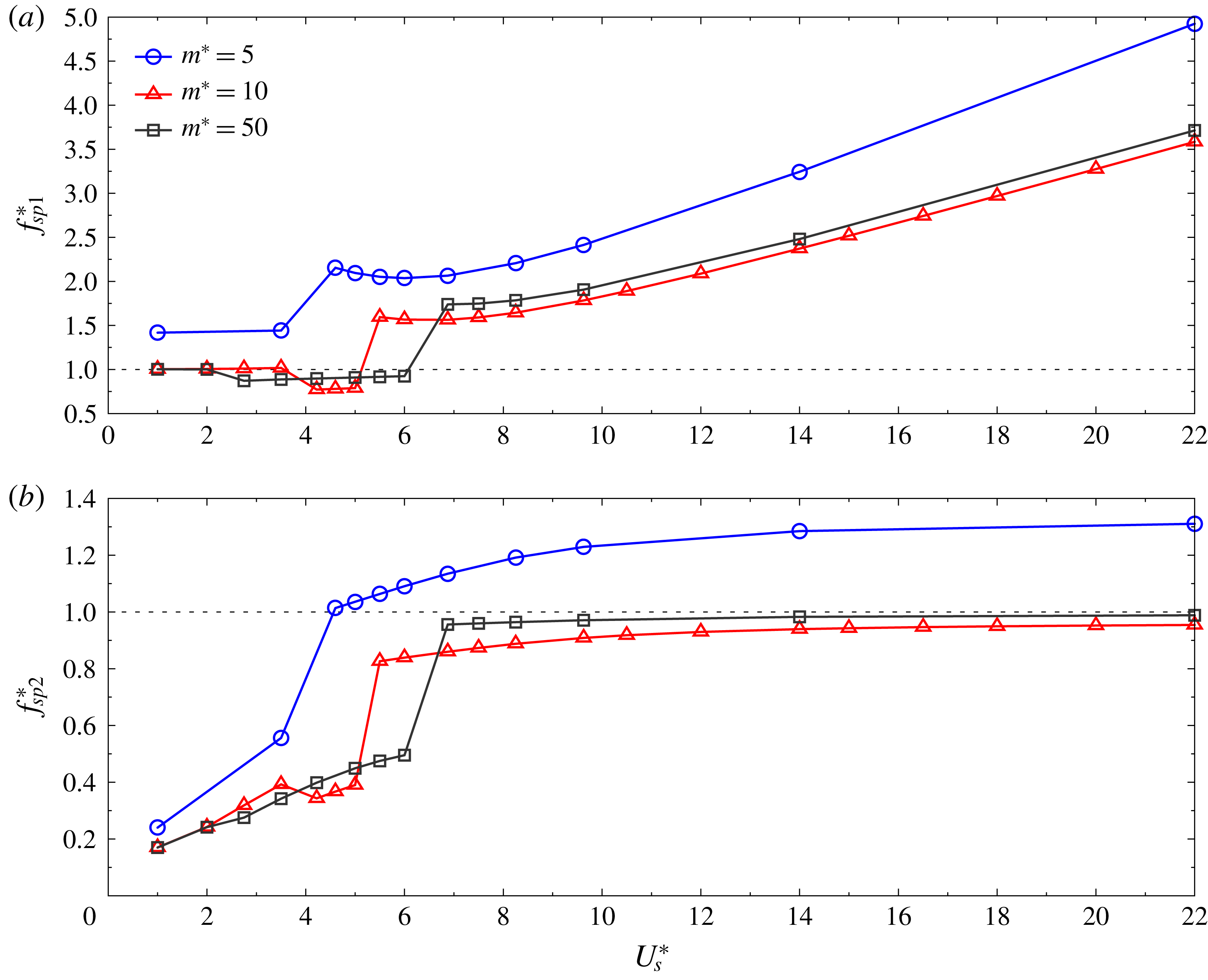
The
 $Re=150$
,
 $L=3.5D$
flow past a spring-mounted circular cylinder with a flexible splitter plate (
 ${\mathcal{C}}_{vib}{\mathcal{P}}_{vib}$
): variation of frequency ratio calculated using the natural frequency of the (a) first (
 $f_{sp1}^{\ast }$
) and (b) second (
 $f_{sp2}^{\ast }$
) mode of the system
 ${\mathcal{C}}_{vib}{\mathcal{P}}_{vib}$
with reduced velocity
 $U_{s}^{\ast }$
.

The
 $Re=150$
,
 $L=3.5D$
flow past a spring-mounted cylinder with flexible splitter plate (
 ${\mathcal{C}}_{vib}{\mathcal{P}}_{vib}$
): effect of plate flexibility,
 $U_{p}^{\ast }$
, on the extent of the various flow regimes in terms of
 $U_{s}^{\ast }$
and the peak response of the cylinder and plate tip.

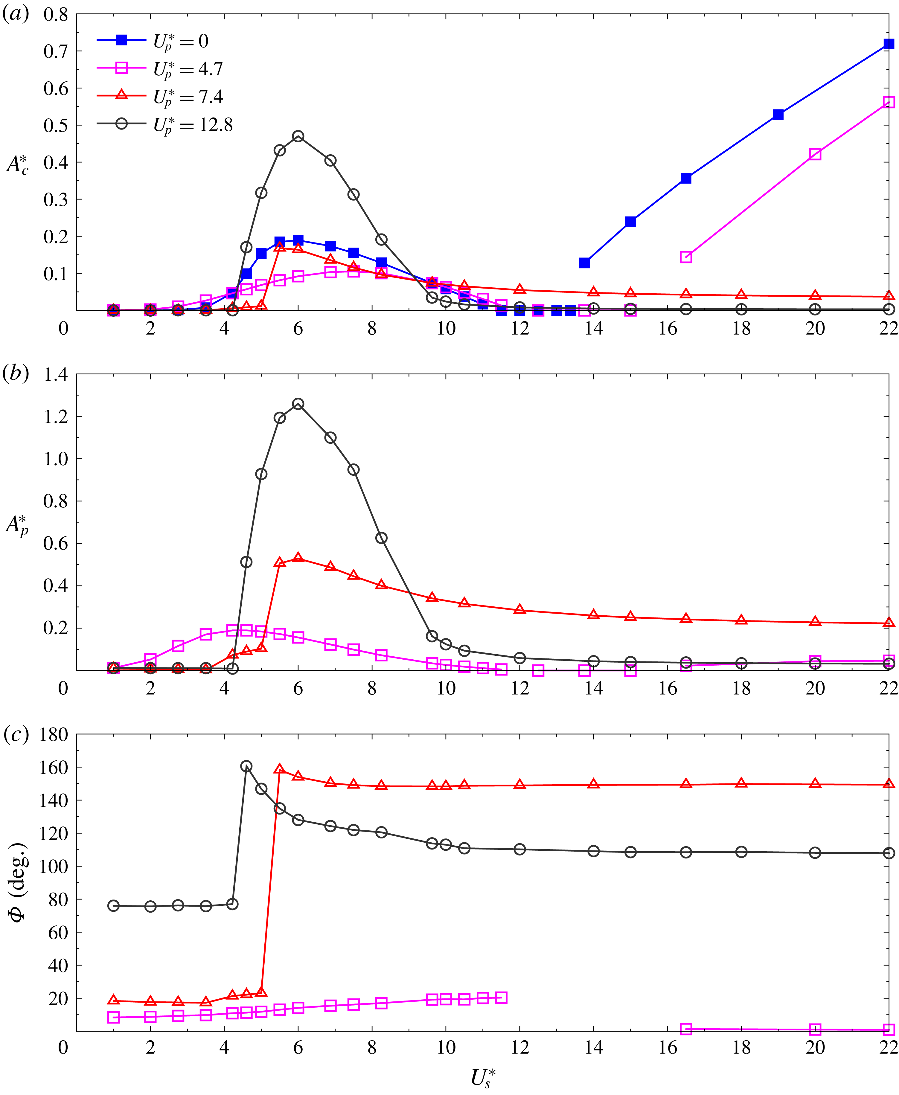
The response of the cylinder with flexible splitter plate of length
 $L=3.5D$
is investigated for three flexibilities. These correspond to
 $U_{p}^{\ast }=$
 $4.7$
,
 $7.4$
and
 $12.8$
. Their responses, along with that for the rigid plate (from figure 14
a) are shown in figure 16. For the case of the rigid plate, there is no relative motion between the plate and the cylinder. Therefore,
 $A_{p}^{\ast }$
is zero and is not shown in figure 16(b). The flow and response regimes (VIV, steady and galloping) with respect to
 $U_{s}^{\ast }$
, for various
 $U_{p}^{\ast }$
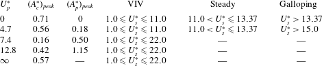
, are summarized in table 4. Qualitatively,
 $U_{p}^{\ast }=4.7$
is similar to the cylinder with rigid splitter plate (
 $U_{p}^{\ast }=0$
) while
 $U_{p}^{\ast }=12.8$
has similarities with the freely vibrating isolated cylinder. Note
 $U_{p}^{\ast }=\infty$
corresponds to the isolated cylinder in table 4. The galloping behaviour is observed for low values of
 $U_{p}^{\ast }$
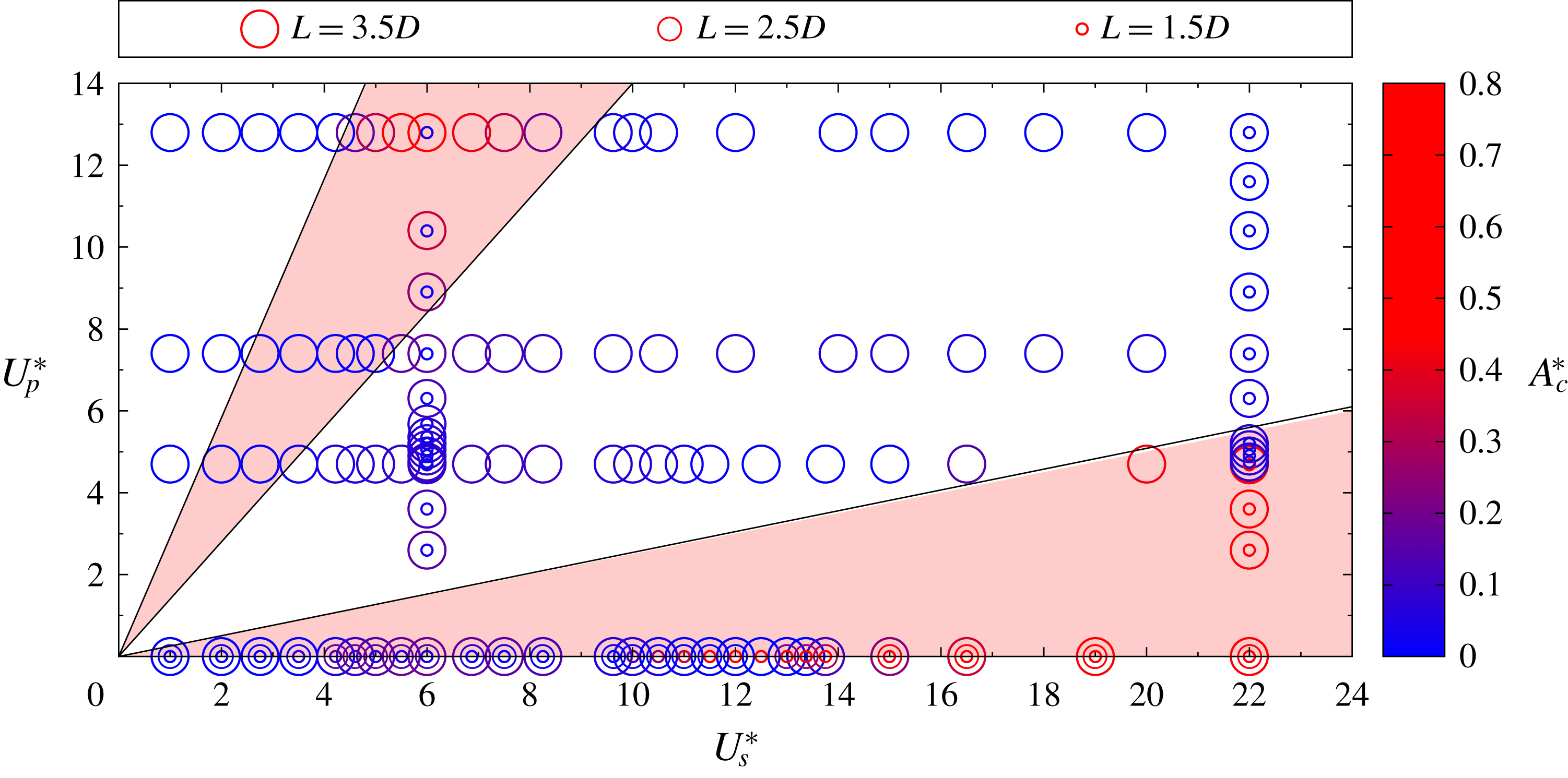
, i.e. for plates that are relatively stiff in bending. In these cases, compared to the isolated cylinder, the peak amplitude of VIV is lower. On the other hand, reducing stiffness of the splitter plate alleviates galloping but encourages VIV. This suggests that it should be possible to find an optimal bending stiffness for which the VIV is minimal, yet for which the system does not exhibit galloping. This, as well as the effect of the length of the splitter plate, is addressed later in the paper.
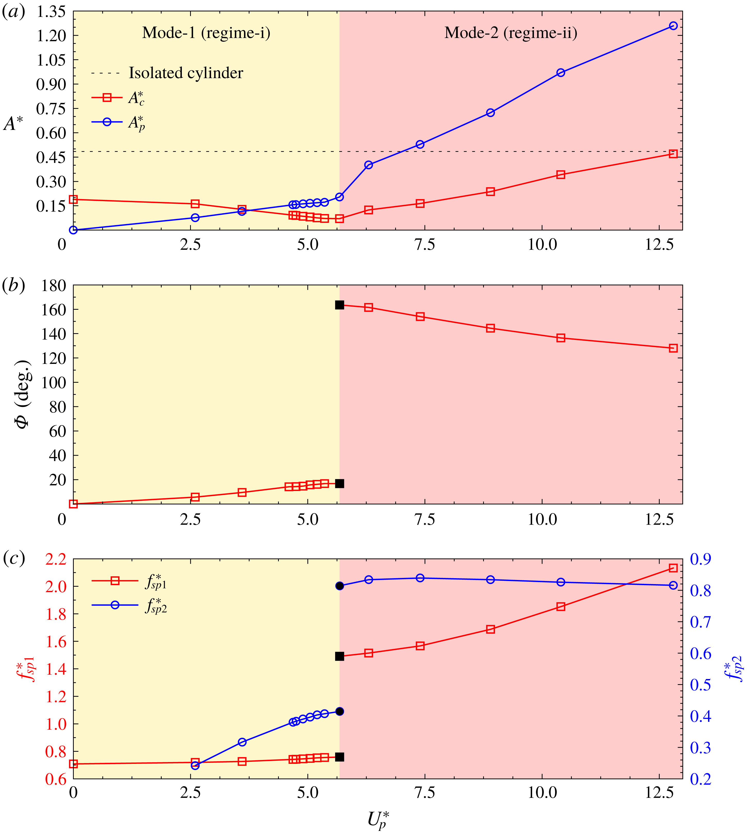
Figure 16(c) shows the phase angle,
 $\unicode[STIX]{x1D6F7}$
, between the vibration of the cylinder and the tip of the plate. Here
 $\unicode[STIX]{x1D6F7}$
is zero for a rigid plate, and is not shown in the figure. For relatively stiff plates (e.g.
 $U_{p}^{\ast }=4.7$
), VIV is weak and the phase between the motion of the cylinder and the tip of the plate stays low. In the galloping regime, for this case, the two are completely in phase. The variation of
 $\unicode[STIX]{x1D6F7}$
with
 $U_{s}^{\ast }$
is rather interesting for plates with higher flexibility (e.g.
 $U_{p}^{\ast }=7.4$
and
 $12.8$
). Even for low amplitude of VIV (low
 $U_{s}^{\ast }$
),
 $\unicode[STIX]{x1D6F7}$
is relatively large. It undergoes a sharp increase at
 $U_{s}^{\ast }$
when the amplitude of cylinder vibration reaches approximately
 $0.2D$
. To understand this behaviour we re-look at the natural modes of vibration of the structure shown in figures 3 and 4. The modes depend on the similarity variables
 $U_{p}^{\ast }F_{nsp}^{k}$
and
 $U_{s}^{\ast }F_{nsp}^{k}$
.
The
 $Re=150$
,
 $U_{s}^{\ast }=6$
,
 $L=3.5D$
flow past a spring-mounted circular cylinder with a flexible splitter plate (
 ${\mathcal{C}}_{vib}{\mathcal{P}}_{vib}$
): variation of (a) normalized amplitude of cylinder oscillation
 $A_{c}^{\ast }$
and plate-tip oscillation
 $A_{p}^{\ast }$
, (b) phase difference between the motion of cylinder and plate tip
 $\unicode[STIX]{x1D6F7}$
and (c) frequency ratios
 $f_{sp1}^{\ast }$
and
 $f_{sp2}^{\ast }$
calculated, respectively, using the first and second natural frequencies of the
 ${\mathcal{C}}_{vib}{\mathcal{P}}_{vib}$
modes with plate flexibility
 $U_{p}^{\ast }$
. The points corresponding to the transition state are shown with solid symbols in (b,c).

For the values of
 $U_{p}^{\ast }$
and
 $U_{s}^{\ast }$
explored in this study, the variables
 $U_{p}^{\ast }F$
and
 $U_{s}^{\ast }F$
are restricted to
 $2.5$
and
 $4.5$
, respectively. Figure 4 shows that the system is associated with only two eigenmodes for these values of the similarity variables. The deflection of the plate in both the modes corresponds to the first mode for the
 ${\mathcal{C}}_{stat}{\mathcal{P}}_{vib}$
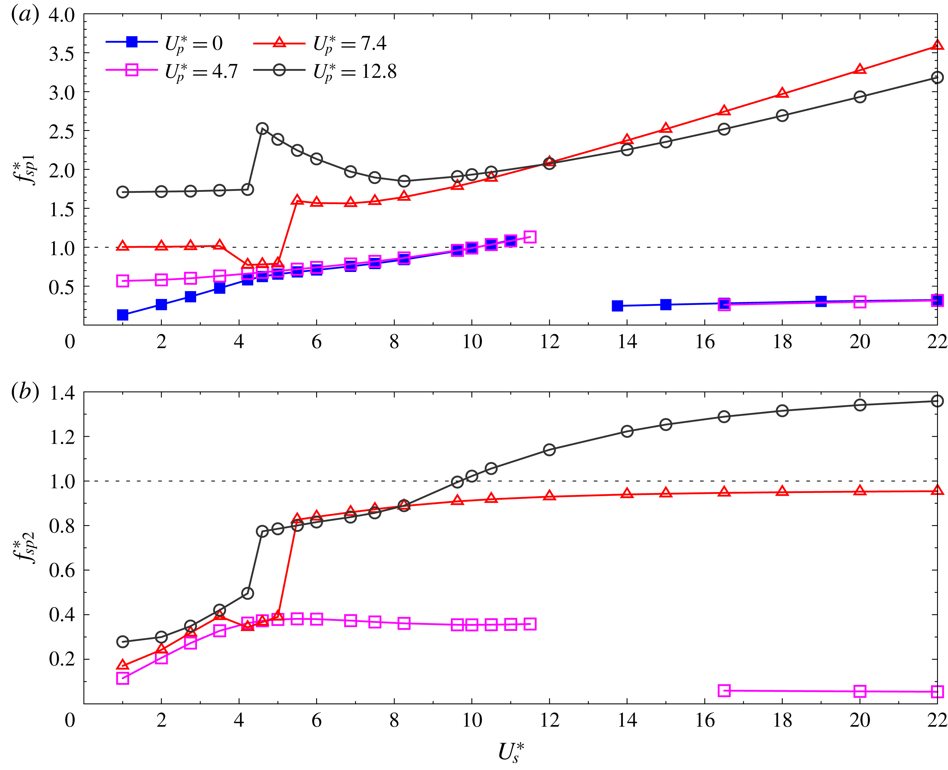
system (stationary cylinder, vibrating plate). The difference between the two eigenmodes is in the phase between the deflection of the cylinder and the tip of the plate. They are in phase for the first mode and out of phase for the second. The eigenvalues corresponding to the two modes are, of course, different. Figure 17 shows the frequency ratio of the freely vibrating
 ${\mathcal{C}}_{vib}{\mathcal{P}}_{vib}$
system. The vibration frequency is non-dimensionalized with the eigenfrequency of the first and second mode in figures 17(a) and 17(b), respectively.
It is noted from this figure that for
 $U_{p}^{\ast }=4.7$
,
 $f_{sp2}^{\ast }$
is significantly lower than unity for all
 $U_{s}^{\ast }$
while
 $f_{sp1}^{\ast }$
is closer to one in the regime of VIV. This signifies a greater relevance of the first mode of the system
 ${\mathcal{C}}_{vib}{\mathcal{P}}_{vib}$
in VIV. For
 $U_{p}^{\ast }=7.4$
,
 $f_{sp1}^{\ast }$
is close to one and
 $f_{sp2}^{\ast }$
is significantly lower for
 $U_{s}^{\ast }<5$
. At
 $U_{s}^{\ast }\sim 5$
,
 $f^{\ast }$
experiences a sharp increase;
 $f_{sp2}^{\ast }$
becomes closer to unity while
 $f_{sp1}^{\ast }$
moves away from unity, suggesting a change in the relevance of the participating eigenmodes. This shift corresponds to a sharp increase in the amplitude of vibration as well as a change in phase between the vibration of cylinder and plate. For
 $U_{p}^{\ast }=12.8$
, in the VIV regime,
 $f_{sp2}^{\ast }$
is closer to unity compared to
 $f_{sp1}^{\ast }$
. This correlates well with the phase as shown in figure 16.
Next, the effect of the flexibility of the plate, by varying
 $U_{p}^{\ast }$
, is investigated for two values of
 $U_{s}^{\ast }$
: 6 and 22. As seen from figure 16, the system is in the VIV regime for
 $U_{s}^{\ast }=6$
and exhibits close to the maximum amplitude of vibration for each
 $U_{p}^{\ast }$
. For relatively rigid plates,
 $U_{s}^{\ast }=22$
lies in the galloping regime. Therefore, computations for various
 $U_{p}^{\ast }$
for this fixed value of
 $U_{s}^{\ast }$
can help in identifying the critical flexibility of the plate beyond which galloping ceases to occur.
3.6.1
$U_{s}^{\ast }=6$
, effect of flexibility of splitter plate (
$U_{p}^{\ast }$
) on VIV


The
 $Re=150$
,
 $U_{s}^{\ast }=6$
,
 $L=3.5D$
flow past a spring-mounted circular cylinder with a flexible splitter plate (
 ${\mathcal{C}}_{vib}{\mathcal{P}}_{vib}$
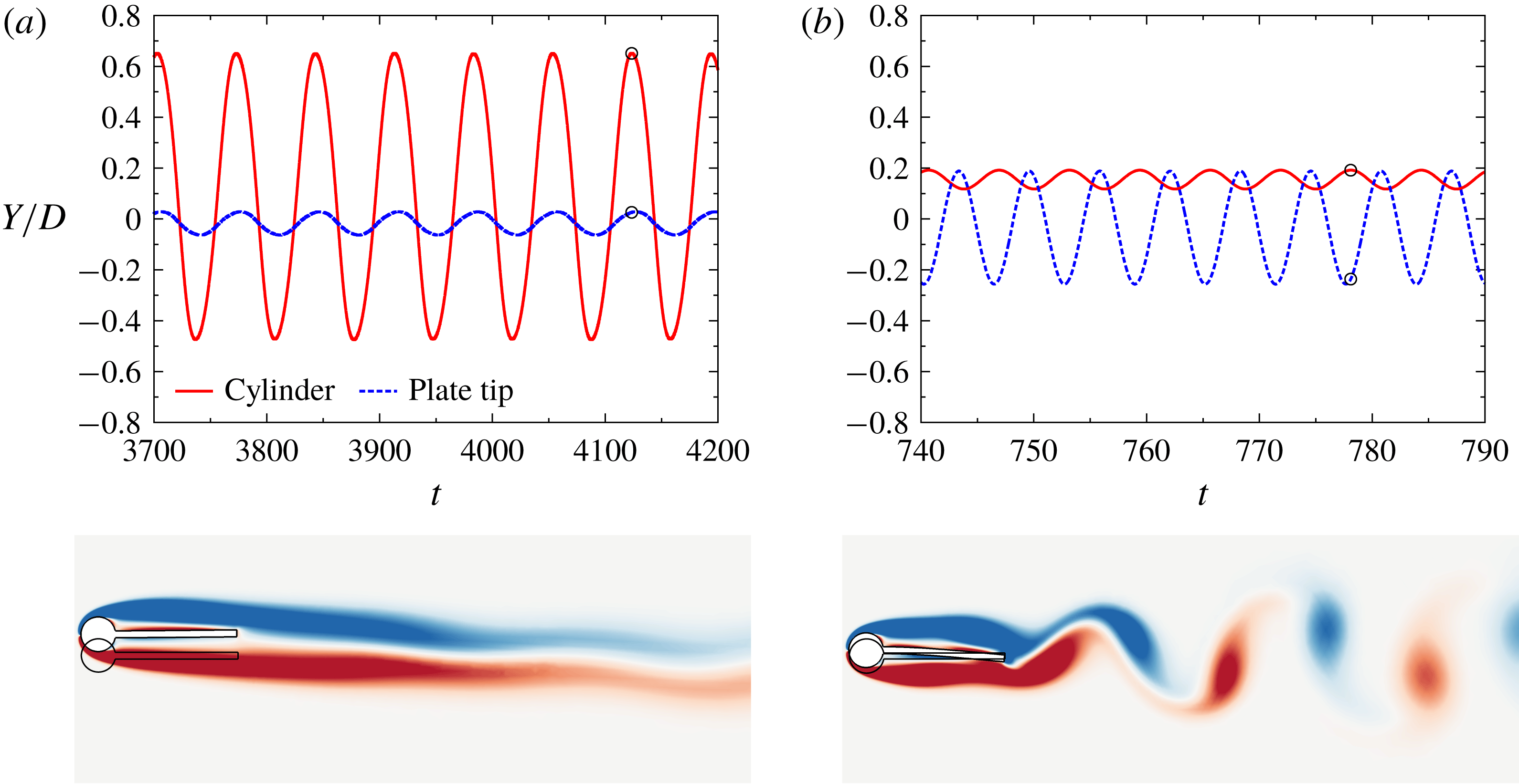
): time histories of cylinder location and that of the plate tip for (a)
 $U_{p}^{\ast }=5.36$
(regime-i) and (b)
 $U_{p}^{\ast }=12.8$
(regime-ii). Vorticity field at a time instant when the cylinder displacement is maximum, and marked in the time histories, is shown below the respective time histories. For reference, the undeformed structure is also shown.

The
 $Re=150$
,
 $U_{s}^{\ast }=6$
,
 $U_{p}^{\ast }=5.68$
,
 $L=3.5D$
flow past a spring-mounted circular cylinder with a flexible splitter plate (
 ${\mathcal{C}}_{vib}{\mathcal{P}}_{vib}$
): (a) time histories of cylinder and plate-tip displacements and (b) vorticity field showing
 $P+S$
mode of vortex shedding. For comparison, the
 $2S$
mode of vortex shedding for
 $U_{p}^{\ast }=12.8$
is shown in (c).

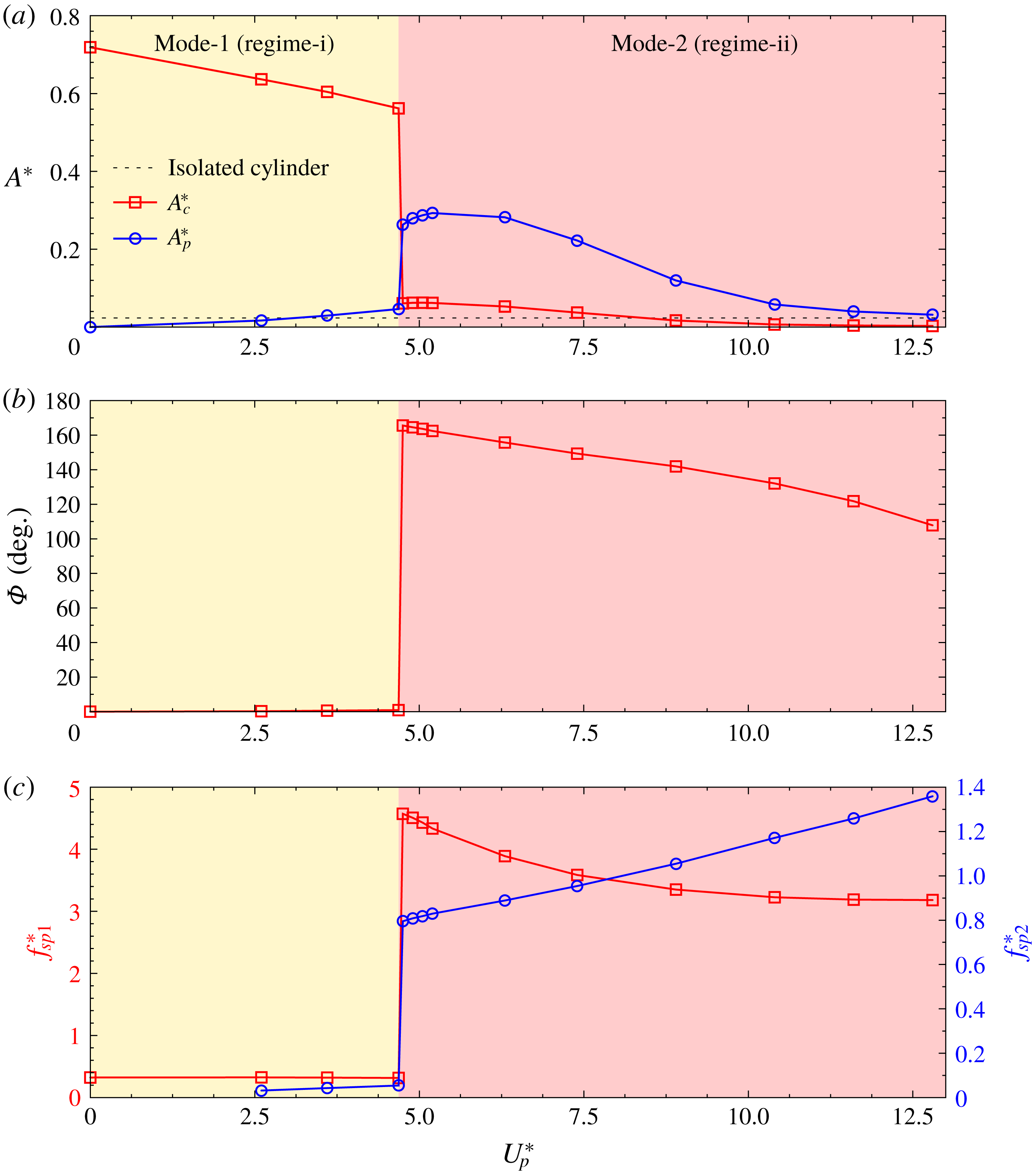
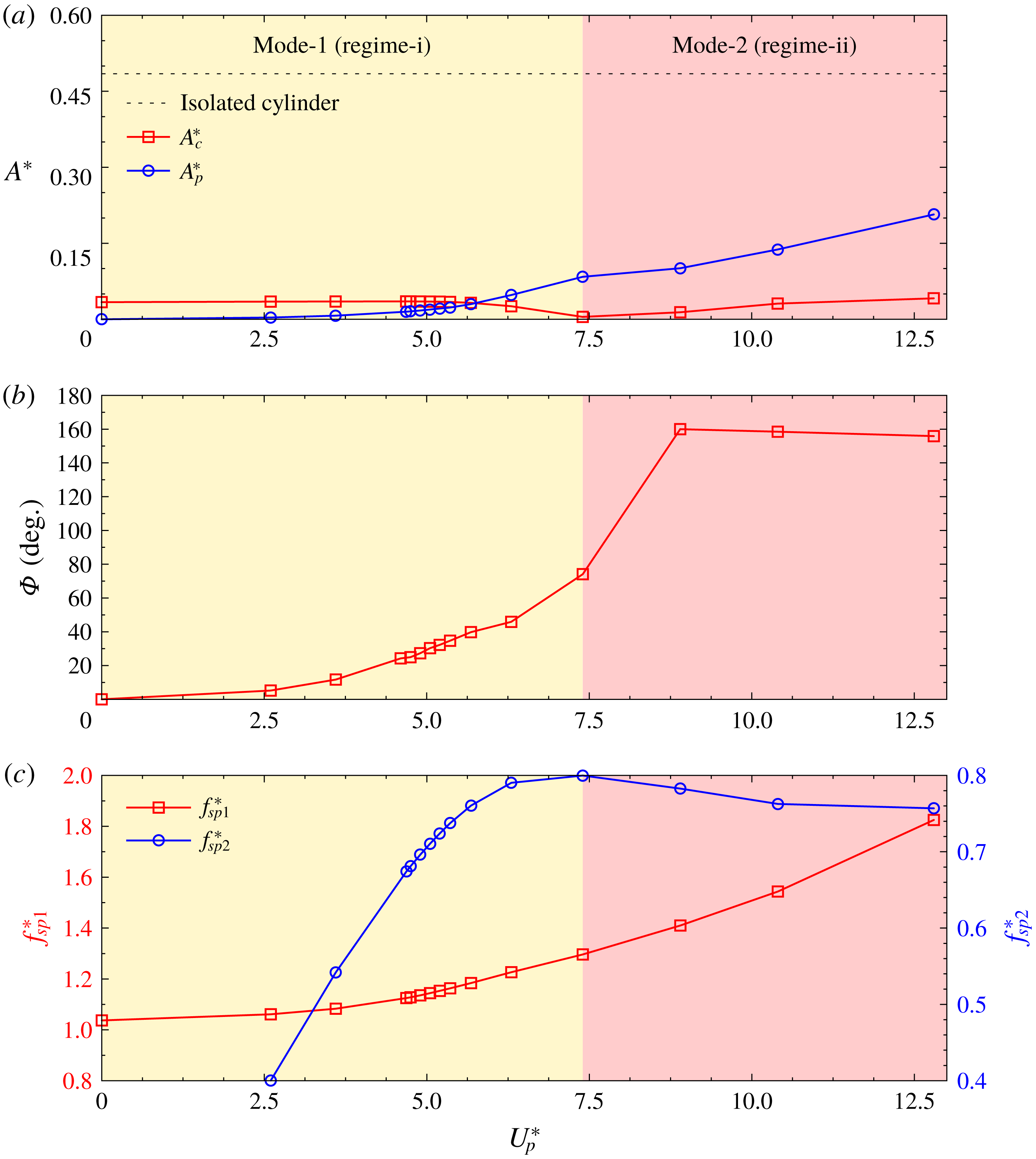
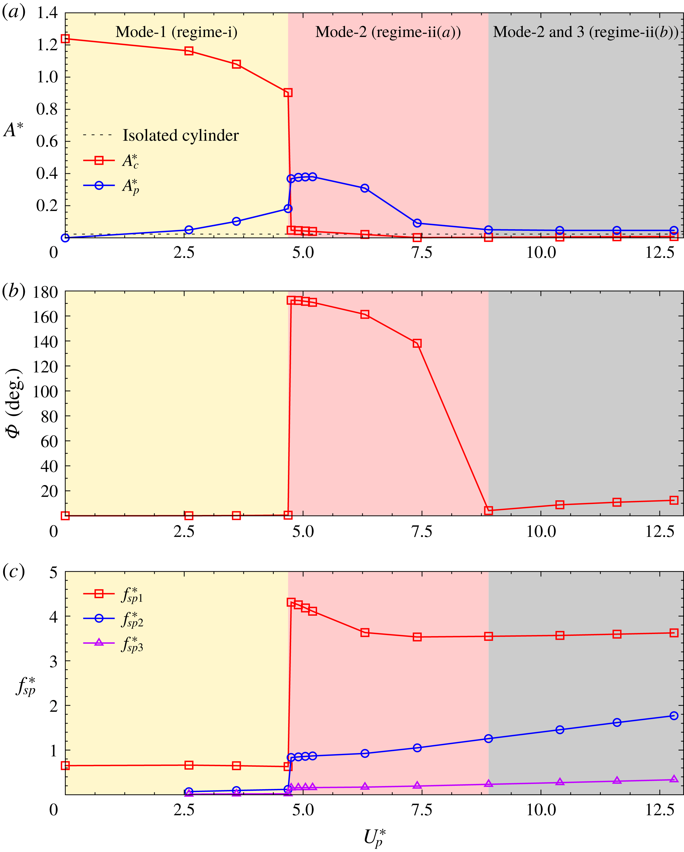
Figure 18 shows the variation of the normalized amplitude of vibration of the cylinder as well as the tip of the splitter plate, relative to the centre of the cylinder, with
 $U_{p}^{\ast }$
. Also shown is the phase between the vibration of cylinder and tip of the splitter plate as well as the vibration frequency, normalized with the first and second natural frequency of the structure. Two regimes are identified from this figure. Regime-i:
 $U_{p}^{\ast }<5.68$
, wherein the system response is closer to the first natural mode of vibration; and regime-ii:
 $U_{p}^{\ast }>5.68$
, where the response is closer to the second mode. The cylinder vibration amplitude is lowest at
 $U_{p}^{\ast }=5.68$
. The response amplitude of the splitter plate, relative to the cylinder, increases with an increase in
 $U_{p}^{\ast }$
. Figure 19 shows the time histories of the response of the structure as well as the unsteady flow for two values of
 $U_{p}^{\ast }$
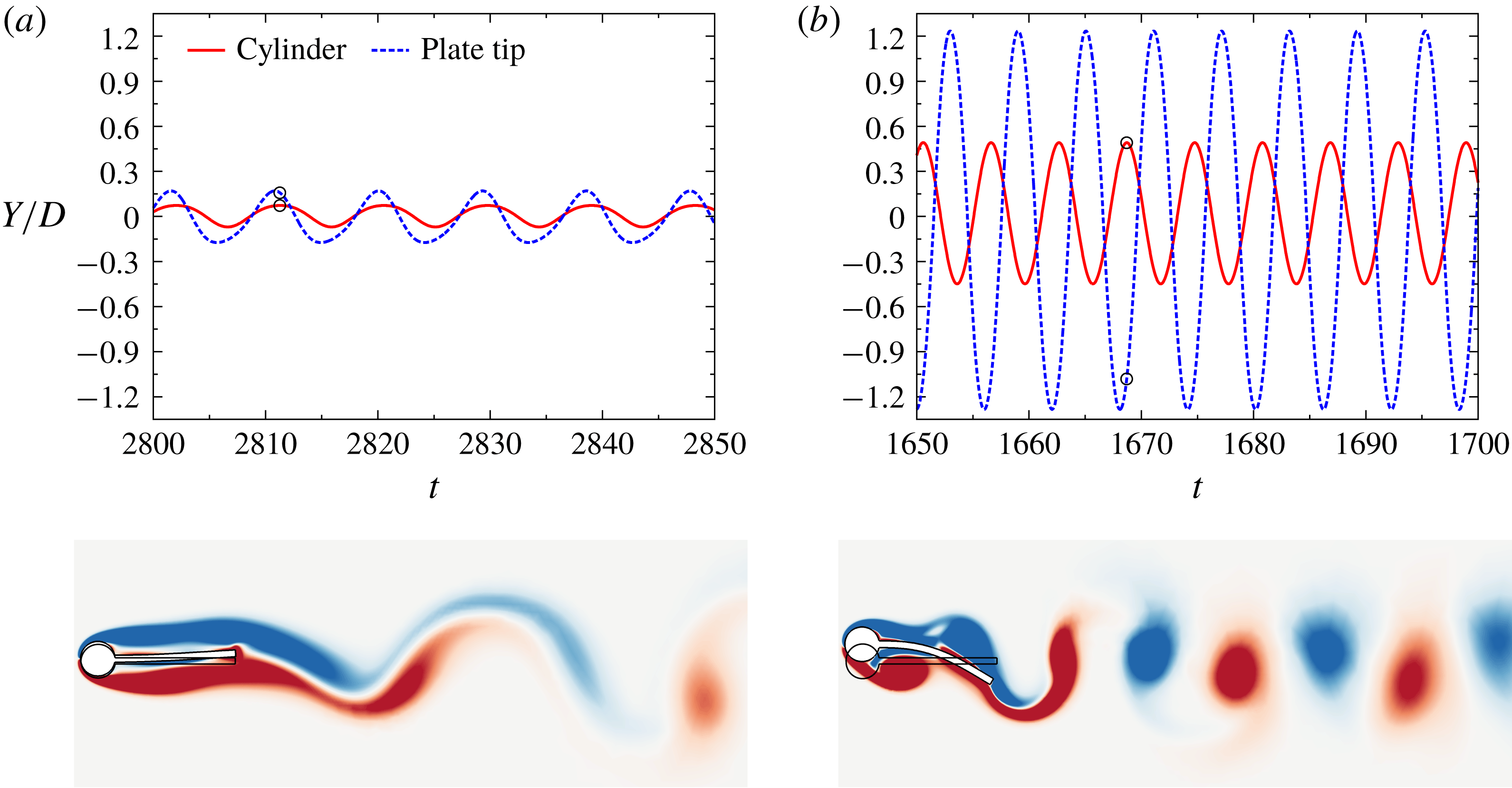
; one each in the two regimes. As seen from the figure, the motions of the cylinder and the tip of the splitter plate are in phase for
 $U_{p}^{\ast }=5.36$
(regime-i) and almost out of phase for
 $U_{p}^{\ast }=12.8$
(regime-ii). The deformed shape of the plate confirms the dominance of the first mode in regime-i and that of the second mode in regime-ii. We recall that, for fixed
 $U_{s}^{\ast }$
, the first mode is associated with a lower natural frequency compared to the second mode (figure 3). This difference is also seen in the vortex shedding frequency in the flow pictures for the two values of
 $U_{p}^{\ast }$
. However, the mode of vortex shedding in both regimes is 2S, wherein two vortices of opposite sign are shed during one cycle of vortex shedding. Figure 20(c) shows the flow at various time instants during one cycle of plate motion for
 $U_{p}^{\ast }=12.8$
. The generation of vortices and their convection in the wake are demonstrated in the figure.
The case of
 $U_{p}^{\ast }=5.68$
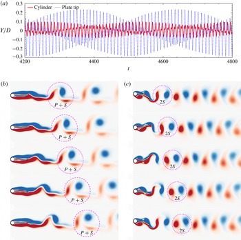
is particularly interesting; it represents the transition between regime-i and regime-ii. The time histories of the response of the structure are shown in figure 20(a). Fast Fourier transform of the signals reveals that there are two frequencies at play: their non-dimensional values are
 $0.106$
and
 $0.209$
. The beats in the time histories are a consequence of the larger frequency being slightly less than twice the smaller one. The lower frequency is closer to the variation observed along the branch corresponding to regime-i, while the larger one belongs to the branch for regime-ii. The phase difference between the motion of cylinder and plate tip, corresponding to each of the frequency variations, was estimated. It is found that the motion of cylinder and plate tip are in phase for the lower frequency and out of phase for the larger frequency, again consistent with the characteristics of regime-i and regime-ii. The phase and normalized frequencies are marked with filled symbols in figure 18 to indicate that they exhibit multiple values during the transition. The flow at various time instants during one cycle of plate motion is shown in figure 20(b). For comparison, the flow for
 $U_{p}^{\ast }=12.8$
is shown as well in figure 20(c). Unlike the 2S mode of shedding observed in regime-i and regime-ii (figure 19
a,b), the vortex shedding pattern for this transitional state (
 $U_{p}=5.68$
) is
 $P+S$
(figure 20
b). A single vortex and a pair of counter-rotating vortices are formed during each cycle of vortex shedding.
3.6.2
$U_{s}^{\ast }=22$
, effect of flexibility of splitter plate (
$U_{p}^{\ast }$
) on galloping


The
 $Re=150$
,
 $U_{s}^{\ast }=22$
,
 $L=3.5D$
flow past a spring-mounted circular cylinder with a flexible splitter plate (
 ${\mathcal{C}}_{vib}{\mathcal{P}}_{vib}$
): variation of (a) normalized amplitude of cylinder oscillation
 $A_{c}^{\ast }$
and plate-tip oscillation
 $A_{p}^{\ast }$
, (b) phase difference between the motion of cylinder and plate tip
 $\unicode[STIX]{x1D6F7}$
and (c) frequency ratios
 $f_{sp1}^{\ast }$
and
 $f_{sp2}^{\ast }$
calculated, respectively, using the first and second natural frequencies of the
 ${\mathcal{C}}_{vib}{\mathcal{P}}_{vib}$
modes with plate flexibility
 $U_{p}^{\ast }$
.

The
 $Re=150$
,
 $U_{s}^{\ast }=22$
,
 $L=3.5D$
flow past a spring-mounted circular cylinder with a flexible splitter plate (
 ${\mathcal{C}}_{vib}{\mathcal{P}}_{vib}$
): time histories of cylinder and plate tip positions for (a)
 $U_{p}^{\ast }=4.68$
(galloping) and (b)
 $U_{p}^{\ast }=7.4$
(VIV). Vorticity field at a time instant when the cylinder displacement is maximum is shown below the respective time histories. For reference, the undeformed structure is also shown.

The effect of flexibility of the plate on galloping is explored. A reasonably large value of
 $U_{s}^{\ast }$
is chosen for the study so that the galloping response, if present, is of relatively large amplitude. Figure 21 shows the variation of the normalized amplitude of vibration of the cylinder as well as the tip of the splitter plate, relative to the centre of the cylinder, with
 $U_{p}^{\ast }$
. Also shown is the phase between the vibration of cylinder and tip of the splitter plate as well as the vibration frequency, normalized with the first and second natural frequency of the structure. Two regimes are identified from this figure. Regime-i:
 $U_{p}^{\ast }\leqslant 4.68$
, wherein the system exhibits galloping response; and regime-ii:
 $U_{p}^{\ast }>4.68$
, where the system undergoes VIV. Interestingly, the phase between the motion of the cylinder and plate tip also undergoes a jump at
 $U_{p}^{\ast }=4.68$
; the motion is in phase in regime-i and nearly out of phase in regime-ii. Figure 22 shows the time histories of the response at a representative
 $U_{p}^{\ast }$
(
 $=4.68$
) in the galloping regime (regime-i). In this regime, the motions of the cylinder and tip of the plate are in phase. In fact, the tip of the plate moves very little relative to the cylinder. It can be seen from the figure that the mean position of the cylinder and plate tip is different from that in the undeformed configuration. A similar behaviour was also observed by Wu et al. (Reference Wu, Qiu, Shu and Zhao2014a
) for certain cases of an elastically mounted cylinder with an attached filament. Also shown is the vorticity field for the instant when the cylinder and the tip of the plate are at their maximum displacement. The vortex shedding occurs a few plate lengths downstream in the wake and with a relatively low frequency. As seen from figure 21, the amplitude of the cylinder response undergoes a sharp reduction when
 $U_{p}^{\ast }$
is increased beyond
 $4.68$
and the system enters the regime of VIV (regime-ii). The amplitude of the response of the tip of the plate rises sharply. It increases on increasing
 $U_{p}^{\ast }$
up to approximately
 $5.0$
. Beyond
 $U_{p}^{\ast }=5$
, the response amplitude decreases with further increase in
 $U_{p}^{\ast }$
. The system vibrates at a frequency close to the natural frequency of the second mode. The time histories of the response are shown in figure 22(b) for a representative
 $U_{p}^{\ast }$
(
 $=7.4$
) in this regime (regime-ii). Also shown is the flow when the cylinder is at the peak displacement. The vortex shedding, in this case, occurs in the very near wake of the cylinder. In both the flow pictures (regime-i and regime-ii), the vortex shedding is of the type 2S, where two vortices of opposite signs are shed during each cycle of shedding.
The studies for
 $U_{s}^{\ast }=6$
and
 $22$
can be utilized to identify optimal flexibility of the plate to minimize FIV. Large-amplitude galloping response can be avoided by choosing a splitter plate with
 $U_{p}^{\ast }\geqslant 4.68$
. In fact, for
 $U_{s}^{\ast }=22$
, the amplitude of galloping response decreases with an increase in
 $U_{p}^{\ast }$
. Therefore, the larger the value of
 $U_{p}^{\ast }$
, the smaller is the amplitude of galloping. However, large values of
 $U_{p}^{\ast }$
are associated with large amplitude of VIV. The amplitude of VIV, for
 $U_{s}^{\ast }=6$
, is minimum for
 $U_{p}^{\ast }=5.68$
. Therefore,
 $U_{p}^{\ast }=5.68$
corresponds to the optimal flexibility of the plate for restricting both galloping and VIV.
3.6.3 Effect of length of splitter plate on VIV (
$U_{s}^{\ast }=6$
) and galloping (
$U_{s}^{\ast }=22$
)


The
 $Re=150$
,
 $U_{s}^{\ast }=6$
,
 $L=1.5D$
flow past a spring-mounted circular cylinder with a flexible splitter plate (
 ${\mathcal{C}}_{vib}{\mathcal{P}}_{vib}$
): variation of (a) normalized amplitude of cylinder oscillation
 $A_{c}^{\ast }$
and plate-tip oscillation
 $A_{p}^{\ast }$
, (b) phase difference between the motion of cylinder and plate tip
 $\unicode[STIX]{x1D6F7}$
and (c) frequency ratios
 $f_{sp1}^{\ast }$
and
 $f_{sp2}^{\ast }$
calculated, respectively, using the first and second natural frequencies of the
 ${\mathcal{C}}_{vib}{\mathcal{P}}_{vib}$
modes with plate flexibility
 $U_{p}^{\ast }$
.

The
 $Re=150$
,
 $U_{s}^{\ast }=22$
,
 $L=1.5D$
flow past a spring-mounted circular cylinder with a flexible splitter plate (
 ${\mathcal{C}}_{vib}{\mathcal{P}}_{vib}$
): variation of (a) normalized amplitude of cylinder oscillation
 $A_{c}^{\ast }$
and plate-tip oscillation
 $A_{p}^{\ast }$
, (b) phase difference between the motion of cylinder and plate tip
 $\unicode[STIX]{x1D6F7}$
and (c) frequency ratios
 $f_{sp1}^{\ast }$
,
 $f_{sp2}^{\ast }$
and
 $f_{sp3}^{\ast }$
calculated, respectively, using the first, second and third natural frequencies of the
 ${\mathcal{C}}_{vib}{\mathcal{P}}_{vib}$
modes with plate flexibility
 $U_{p}^{\ast }$
.

To investigate the effect of plate length on FIV, we study the response of the
 ${\mathcal{C}}_{vib}{\mathcal{P}}_{vib}$
system with
 $L=1.5D$
and compare it to that for
 $L=3.5D$
. Figures 23 and 24 present the variation of normalized amplitudes, the phase difference
 $\unicode[STIX]{x1D6F7}$
and the frequency ratios for
 $U_{s}^{\ast }=6$
and
 $22$
, respectively, just as figures 18 and 21 do for
 $L=3.5D$
. Figure 23(b,c) shows that for
 $L=1.5D$
and
 $U_{p}^{\ast }\lesssim 2.6$
, the cylinder and the plate tip oscillate nearly in phase with a frequency close to
 $F_{nsp1}$
. On the other hand, the two oscillate out of phase and with a frequency close to
 $F_{nsp2}$
for
 $U_{p}^{\ast }\gtrsim 8.9$
. Thus, as in the case of
 $L=3.5D$
, VIV response of the system is dominated by the first
 ${\mathcal{C}}_{vib}{\mathcal{P}}_{vib}$
mode at low
 $U_{p}^{\ast }$
and the second mode at large
 $U_{p}^{\ast }$
. However, unlike for the longer plate, the transition from the first mode behaviour to the second is gradual. Figure 23(a) shows that the variation in cylinder and plate-tip amplitudes is also qualitatively similar to that for
 $L=3.5D$
(figure 18
a). However, amplitude at each value of
 $U_{p}^{\ast }$
is smaller compared to the corresponding value for
 $L=3.5D$
. This is primarily because, for a given
 $U_{p}^{\ast }$
, the
 $U_{s}^{\ast }$
, at which the amplitude of plate vibration is maximum, decreases with a decrease in
 $L$
(figure 14
a). The amplitude of plate vibration is close to maximum at
 $U_{s}^{\ast }\sim 6$
for
 $L=3.5D$
while it occurs at
 $U_{s}^{\ast }\sim 4$
for
 $L=1.5D$
.
Figure 24 shows that, as for
 $L=3.5D$
(figure 21), the critical value of
 $U_{p}^{\ast }$
, for onset of galloping, is
 $4.68$
. For both the plate lengths, galloping occurs for
 $U_{p}^{\ast }\leqslant 4.68$
(regime-i). However, the frequency of vibration is closer to
 $F_{nsp1}$
for the shorter plate, compared to the longer one. Also, the amplitude of galloping is higher for
 $L=1.5D$
. The vortex shedding is relatively strong, in the near wake, for the shorter plate even during galloping. Such a phenomenon has also been observed in the past and is referred to as VIV–galloping interaction (Liang et al.
Reference Liang, Wang and Hu2018). Regime-ii (
 $U_{p}^{\ast }>4.68$
), for
 $L=1.5D$
, can be further divided into two subregimes: regime-ii(a) and regime-ii(b). Regime-ii(a),
 $4.68<U_{p}^{\ast }\leqslant 7.4$
, is similar to the regime-ii for
 $L=3.5D$
(figure 21). No galloping is observed in this regime, leading to a drastic reduction in the amplitude of cylinder vibration. However, the amplitude of plate vibration increases sharply as the system transits from regime-i to regime-ii(a). The cylinder and plate oscillate almost out of phase, with a frequency close to the second natural frequency
 $F_{nsp2}$
. In regime-ii(b), which occurs for
 $U_{p}^{\ast }\gtrsim 7.4$
, the cylinder and the plate tip again oscillate in phase. Both are associated with a relatively small amplitude. Figures 3 and 4 show that the plate and cylinder vibrate in phase for the first and third modes of vibration of
 ${\mathcal{C}}_{vib}{\mathcal{P}}_{vib}$
, while they are out of phase for the second mode. Therefore, either the first or third mode (or both) is significant in regime-ii(b). Figure 24(c) shows that the frequency of vibration in this regime is very different from the first natural frequency (
 $f_{sp1}^{\ast }\gg 1$
). It also shows an increase in
 $f_{sp3}^{\ast }$
, towards a value of
 $1$
, with an increase in
 $U_{p}^{\ast }$
. This indicates that the third mode of vibration, and not the first one, is most significant during regime-ii(b). Figure 23(a) shows that the smallest amplitude of vibration is observed at
 $U_{p}^{\ast }=7.4$
. Since galloping does not occur for
 $U_{p}^{\ast }>4.68$
,
 $U_{p}^{\ast }=7.4$
is close to optimal flexibility of the plate, for
 $L=1.5D$
, for minimizing flow-induced oscillation of the cylinder. We recall that the optimal flexibility, for the longer plate with
 $L=3.5D$
, is lower and corresponds to
 $U_{p}^{\ast }=5.68$
.
3.6.4 Effect of mass ratio and damping on the FIV response
The
 $Re=150$
,
 $U_{p}^{\ast }=7.4$
,
 $L=3.5D$
flow past a spring-mounted circular cylinder with a flexible splitter plate (
 ${\mathcal{C}}_{vib}{\mathcal{P}}_{vib}$
) for three different
 $m^{\ast }$
: variation of the normalized amplitude of (a) cylinder oscillation
 $A_{c}^{\ast }$
and (b) plate-tip vibration
 $A_{p}^{\ast }$
with reduced velocity
 $U_{s}^{\ast }$
. Shown in (c) is the phase difference,
 $\unicode[STIX]{x1D6F7}$
, between the vibration of cylinder and plate-tip displacements.

The
 $Re=150$
,
 $U_{p}^{\ast }=7.4$
,
 $L=3.5D$
flow past a spring-mounted circular cylinder with a flexible splitter plate (
 ${\mathcal{C}}_{vib}{\mathcal{P}}_{vib}$
) for three different
 $m^{\ast }$
: variation of frequency ratio calculated using the natural frequency of the (a) first (
 $f_{sp1}^{\ast }$
) and (b) second (
 $f_{sp2}^{\ast }$
) mode of the system
 ${\mathcal{C}}_{vib}{\mathcal{P}}_{vib}$
with reduced velocity
 $U_{s}^{\ast }$
.

The effect of mass ratio on the FIV of the
 ${\mathcal{C}}_{vib}{\mathcal{P}}_{vib}$
system is studied via computations with three values of mass ratio,
 $m^{\ast }=5,10$
and
 $50$
. Values of
 $U_{p}^{\ast }$
and
 $L$
for the study are fixed at
 $7.4$
and
 $3.5D$
while
 $U_{s}^{\ast }$
is varied. We recall that
 $(U_{p}^{\ast },L)=(7.4,3.5D)$
is associated with a smaller amplitude of cylinder vibration, compared to that of an isolated cylinder, during VIV and, unlike a cylinder with rigid splitter plate, does not gallop at large values of
 $U_{s}^{\ast }$
(see figure 16). Figure 25 shows the variation, with
 $U_{s}^{\ast }$
, of amplitude of oscillation of the cylinder and the plate tip as well as the phase difference between the two for different
 $m^{\ast }$
. The variation of frequency ratios,
 $f_{sp1}^{\ast }$
and
 $f_{sp2}^{\ast }$
, is shown in figure 26. The response is qualitatively quite similar for all
 $m^{\ast }$
. Figure 25(c) shows that the lower values of
 $U_{s}^{\ast }$
are associated with nearly in-phase motion of the cylinder and the plate. Further, it is seen from figure 26(a) that the ratio
 $f_{sp1}^{\ast }$
is near unity for these values of
 $U_{s}^{\ast }$
. It is closer to unity for larger
 $m^{\ast }$
. As also discussed earlier, these are characteristics of a response dominated by the first
 ${\mathcal{C}}_{vib}{\mathcal{P}}_{vib}$
mode. Similar conclusions can be drawn, from figures 25(c) and 26(b), about the role of the second
 ${\mathcal{C}}_{vib}{\mathcal{P}}_{vib}$
mode in the higher
 $U_{s}^{\ast }$
range. Figure 25 shows that the transition from mode 1 to 2 is associated with a sharp jump in the amplitude of vibration of the cylinder as well as the plate. Although the nature of this transition is the same across all values of
 $m^{\ast }$
considered, the quantum of jump and the
 $U_{s}^{\ast }$
at which it occurs depends significantly on
 $m^{\ast }$
. With an increase in
 $m^{\ast }$
, it occurs at larger
 $U_{s}^{\ast }$
and the magnitude of the jump decreases. Interestingly, the vibration amplitude achieves a maximum in mode 2, immediately after the jump. Such a delay in maximum amplitude, with respect to
 $U_{s}^{\ast }$
, was also observed recently by Sahu et al. (Reference Sahu, Furquan, Jaiswal and Mittal2019) for transverse free vibration of a cylinder with a rigid plate. However, unlike in the present study, the cylinder with a rigid plate is associated with only one mode of vibration. Therefore, in their study, a change of mode is not possible and no jump in amplitude of response is observed. Irrespective of
 $m^{\ast }$
,
 $2S$
mode of vortex shedding is observed for all
 $U_{s}^{\ast }$
.
The
 $Re=150$
,
 $m^{\ast }=10$
,
 $U_{p}^{\ast }=7.4$
,
 $L=3.5D$
flow past a spring-mounted circular cylinder with a flexible splitter plate (
 ${\mathcal{C}}_{vib}{\mathcal{P}}_{vib}$
) for three different
 $\unicode[STIX]{x1D701}$
: variation of the normalized amplitude of (a) cylinder oscillation
 $A_{c}^{\ast }$
and (b) plate-tip vibration
 $A_{p}^{\ast }$
with reduced velocity
 $U_{s}^{\ast }$
.

The effect of damping ratio,
 $\unicode[STIX]{x1D701}$
, on the FIV response is studied via three values of
 $\unicode[STIX]{x1D701}$
(0, 0.001 and 0.01). We note that a number of experimental and numerical studies of VIV of an isolated cylinder have used low values of
 $\unicode[STIX]{x1D701}$
of the order of
 $10^{-3}$
(Bishop & Hassan Reference Bishop and Hassan1964; Anagnostopoulos & Bearman Reference Anagnostopoulos and Bearman1992; Brika & Laneville Reference Brika and Laneville1993; Khalak & Williamson Reference Khalak and Williamson1999; Triantafyllou et al.
Reference Triantafyllou, Hover, Techet, Yue, Benaroya and Wei2003; Klamo, Leonard & Roshko Reference Klamo, Leonard and Roshko2006; Blevins & Coughran Reference Blevins and Coughran2009; Prasanth et al.
Reference Prasanth, Premchandran and Mittal2011; Law & Jaiman Reference Law and Jaiman2017). Computations are carried out for each
 $\unicode[STIX]{x1D701}$
at
 $U_{p}^{\ast }=7.4$
,
 $m^{\ast }=10$
and
 $L=3.5D$
and varying
 $U_{s}^{\ast }$
. Figure 27 shows the variation of amplitude of vibration of cylinder and plate tip with
 $U_{p}^{\ast }$
for all three cases. The responses for different values of
 $\unicode[STIX]{x1D701}$
are quite close. The only discernible difference in the response is a slight reduction in the peak value of the amplitude with increasing
 $\unicode[STIX]{x1D701}$
. This is consistent with the earlier studies of VIV of an isolated cylinder at low
 $Re$
(Bahmani & Akbari Reference Bahmani and Akbari2010; Prasanth et al.
Reference Prasanth, Premchandran and Mittal2011).
4 Conclusions
The FIV of a circular cylinder, mounted on an elastic support, with an attached flexible splitter plate (
 ${\mathcal{C}}_{vib}{\mathcal{P}}_{vib}$
) is studied. The compliance of the spring support and the flexibility of the splitter plate are characterized by the reduced speeds
 $U_{s}^{\ast }$
and
 $U_{p}^{\ast }$
, respectively. Their effect on the coupled fluid–structure interaction is investigated in detail. The study is restricted to low
 $Re$
(
 $=150$
) and plates of length
 $1.5D,2.5D$
and
 $3.5D$
. The mass ratio of the structure is
 $m^{\ast }=10$
for most cases. Some cases are also considered for
 $m^{\ast }=5$
and
 $50$
to study the effect of mass ratio. Fluid-only computations for a stationary cylinder with a rigid splitter plate show that the flow is steady up to a certain critical
 $Re$
, which increases with an increase in plate length. The flow at
 $Re=150$
is associated with vortex shedding for all three lengths of plate investigated. However, it is much weaker than for an isolated cylinder without a splitter plate at the same
 $Re$
. The reduced unsteadiness, with the splitter plate, leads to a significant reduction in fluctuations in the fluid forces and mean drag.
Modal analysis is carried out for the systems
 ${\mathcal{C}}_{stat}{\mathcal{P}}_{vib}$
and
 ${\mathcal{C}}_{vib}{\mathcal{P}}_{vib}$
. In this analysis the deformation of the plate is modelled via the Euler–Bernoulli beam theory. The analysis gives insight into how the addition of a degree of freedom associated with the spring–mass system alters the eigenmodes/values of the flexible splitter plate. The deformations of the plate in the first eigenmode of the two systems are very similar. It is found, however, that the deformation of the plate in the
 $k\text{th}$
(
 $k>1$
) eigenmode of the system
 ${\mathcal{C}}_{vib}{\mathcal{P}}_{vib}$
is similar to that in the
 $(k-1)$
th eigenmode of
 ${\mathcal{C}}_{stat}{\mathcal{P}}_{vib}$
for small
 $U_{p}^{\ast }$
and to the
 $k$
th eigenmode for large
 $U_{p}^{\ast }$
. Similarly, the natural frequency corresponding to the
 $k\text{th}$
eigenmode of the system
 ${\mathcal{C}}_{vib}{\mathcal{P}}_{vib}$
is bounded by the
 $k\text{th}$
and
 $(k-1)\text{th}$
natural frequencies of the system
 ${\mathcal{C}}_{stat}{\mathcal{P}}_{vib}$
, i.e.
 $F_{np}^{k-1}\leqslant F_{nsp}^{k}\leqslant F_{np}^{k}$
. It is also found that the cylinder and plate tip move in phase for the odd-numbered modes, and out of phase for the even-numbered ones. In the limit of
 $U_{s}^{\ast }=0$
, the system
 ${\mathcal{C}}_{vib}{\mathcal{P}}_{vib}$
degenerates to
 ${\mathcal{C}}_{stat}{\mathcal{P}}_{vib}$
while it reduces to a mere spring–mass oscillator for
 $U_{p}^{\ast }=0$
.
The FIV for the
 ${\mathcal{C}}_{stat}{\mathcal{P}}_{vib}$
system reveals multiple regions of lock-in with respect to
 $U_{p}^{\ast }$
. The frequency of vibration of the plate in the first region of lock-in is close to
 $F_{np}^{1}$
, and to
 $F_{np}^{2}$
in the second region. Both the regimes are preceded by regions of desynchronization. Compared to the first, the second region of lock-in is associated with stronger vortex shedding and larger amplitude of vibration. The transitions from the desynchronization regions to lock-in are associated with jumps/sharp changes and are hysteretic. In relatively narrow regimes of
 $U_{p}^{\ast }$
, computations with increasing and decreasing
 $U_{p}^{\ast }$
result in vibration of different amplitude and frequency. The present computations, based on a partitioned method wherein the fluid and structure evaluations employ a block-iterative approach, require an extremely small time step for large
 $U_{p}^{\ast }$
, especially when the amplitude of vibration is relatively large. Computations in this study are carried out for
 $U_{p}^{\ast }\leqslant 80$
until the system achieves a limit-cycle response. For higher
 $U_{p}^{\ast }$
, up to
 $100$
, computations are restricted up to the time the amplitude of the displacement of the tip of the plate achieves a certain threshold. It would be interesting, in future work, to extend the computations to larger
 $U_{p}^{\ast }$
to explore lock-in with higher modes. It would also be interesting to carry out a linear stability analysis for the coupled fluid–structure system and track the various branches of unstable modes with respect to
 $U_{p}^{\ast }$
. A similar study was conducted by Navrose & Mittal (Reference Mittal2016) for the
 $C_{vib}$
system.
The FIV for the
 ${\mathcal{C}}_{vib}{\mathcal{P}}_{stat}$
system results in three regimes of response with respect to
 $U_{s}^{\ast }$
. (i) The regime of VIV which is similar to that for the elastically mounted isolated cylinder (
 ${\mathcal{C}}_{vib}$
). However, unlike for
 ${\mathcal{C}}_{vib}$
, the amplitude of response does not exhibit a jump at the onset of lock-in; rather, the variation with
 $U_{s}^{\ast }$
is smooth. The splitter plate causes a significant reduction in the peak oscillation amplitude. Although the maximum amplitude during lock-in is nearly same for all three plate lengths, increasing plate length widens the range of the lock-in region. (ii) In the
 ${\mathcal{C}}_{vib}$
system, the lock-in is preceded and followed by desynchronization. Interestingly, the addition of a sufficiently long (
 $L=3.5D$
) rigid splitter plate causes the fluid–structure system to achieve a steady state beyond the lock-in for a certain range of
 $U_{s}^{\ast }$
. It should be noted that the flow past the stationary system (cylinder with the splitter plate) is unsteady. However, the elastic support appears to render stability to the steady flow in this regime. (iii) Galloping sets in beyond a critical value of
 $U_{s}^{\ast }$
, which increases with the length of the plate.
Flow past a fixed cylinder with a flexible splitter plate (
 ${\mathcal{C}}_{stat}{\mathcal{P}}_{vib}$
): variation of non-dimensionalized amplitude
 $A_{p}^{\ast }$
of the plate-tip displacement with (a) non-dimensional stiffness of the plate
 $K^{\ast }$
and (b) reduced speed
 $U_{p}^{\ast }$
. Open symbols denote data from numerical studies while filled triangles represent data from the experimental study of Shukla et al. (Reference Shukla, Govardhan and Arakeri2013).

The effect of flexibility of plate and spring on the FIV of the
 ${\mathcal{C}}_{vib}{\mathcal{P}}_{vib}$
system is explored. The response of the structure for a sufficiently stiff plate (low
 $U_{p}^{\ast }$
) is very similar to that for the rigid plate; all three regimes of VIV, steady flow and galloping are observed. For a plate that is sufficiently flexible, the system behaves like an isolated cylinder on an elastic support. In this situation, the response of the system is VIV for the entire range of
 $U_{s}^{\ast }$
. The first three eigenmodes of
 ${\mathcal{C}}_{vib}{\mathcal{P}}_{vib}$
play an important role in the range of parameters investigated. For a fixed
 $U_{s}^{\ast }$
, the first mode is dominant up to a certain critical
 $U_{p}^{\ast }$
, beyond which the second mode is the dominant one. For the shorter plate, the third mode along with the second one are observed for large
 $U_{s}^{\ast }$
and
 $U_{p}^{\ast }$
. Galloping occurs at large
 $U_{s}^{\ast }$
and only when
 $U_{p}^{\ast }$
is below the critical value. Only the first mode is observed during galloping. The computations show that, for
 $L=3.5D$
,
 $U_{p}^{\ast }\sim 5.7$
is close to optimal flexibility of the plate for which the vibration amplitude of the cylinder in VIV is minimal and the system does not undergo galloping vibration. The optimal flexibility is found to be slightly higher (
 $U_{p}^{\ast }\sim 7.4$
) for a shorter plate (
 $L=1.5D$
). Effect of mass and damping ratios is also studied. The effect of
 $m^{\ast }$
is more significant compared to that of structural damping. However, increasing either is found to adversely affect the peak amplitude of vibration. The value of
 $U_{s}^{\ast }$
at which the amplitude of vibration, for VIV, is maximum increases with an increase in
 $m^{\ast }$
.
There have been very few studies in the past to investigate FIV of a stationary cylinder with flexible splitter plate. The experimental studies are at relatively large
 $Re$
while the computational ones are at low
 $Re$
. Further, the structural characteristics of the splitter plate as well as its joint with the cylinder vary between the studies. Nevertheless, it is interesting to compare the results from the present study with those available in the literature for a similar problem set-up. The experimental study by Shukla et al. (Reference Shukla, Govardhan and Arakeri2013) is for
 $1800\leqslant Re\leqslant 10\,000$
. The filament is very light in their study and, therefore, the effect of its inertia on the dynamics is negligible. Thus, it is not possible to define a natural frequency for the filament and a corresponding reduced speed. The relevant parameter is the bending coefficient
 $K^{\ast }$
defined as
 $K^{\ast }=EI/\frac{1}{2}\unicode[STIX]{x1D70C}_{f}U^{2}$
. Figure 28(a) shows the variation of amplitude of plate-tip vibration with
 $K^{\ast }$
for their study as well as for others. We again note that the
 $Re$
for the study by Shukla et al. (Reference Shukla, Govardhan and Arakeri2013) is very large, compared to that for the other studies. Figure 28(b) shows the variation of amplitude of plate-tip vibration with
 $U_{p}^{\ast }$
from the different studies, except that of Shukla et al. (Reference Shukla, Govardhan and Arakeri2013). The computational study by Wu et al. (Reference Wu, Qiu, Shu and Zhao2014a
) is at
 $Re=150$
. However, unlike the present study, they used thin filaments which are hinged at the rear of the cylinder. The study by Lee & You (Reference Lee and You2013) is closest to the present set-up. As expected, the results from the two studies are in reasonable agreement, except for the plate of length
 $3D$
at large
 $U_{p}^{\ast }$
where they observe significantly larger amplitude of vibration. All the studies reveal low-amplitude response when the plate stiffness is too high and a sharp rise beyond a certain critical flexibility.
The
 $Re=150$
flow past a spring-mounted circular cylinder with splitter plate amplitude of cylinder vibration for various
 $U_{p}^{\ast }$
and
 $U_{s}^{\ast }$
considered in this study. Coral shade marks those values of
 $U_{p}^{\ast }$
and
 $U_{s}^{\ast }$
wherein high-amplitude oscillation (
 ${\geqslant}0.3D$
) occurs at some flow speed. Designs that correspond to this ratio of
 $U_{p}^{\ast }/U_{s}^{\ast }$
may be avoided for applications where VIV is undesirable. However, such
 $U_{p}^{\ast }/U_{s}^{\ast }$
values can be used for applications like energy harvesting, where a large amplitude of vibration is desirable.

How does one utilize the information from such studies to design systems with minimal FIV of a bluff body? To this extent, we propose a procedure. We note that the cylinder is the main body and the flexible splitter plate is the device for possible annihilation/suppression of FIV. Figure 29 shows the normalized amplitude of cylinder vibration, due either to VIV or galloping, in the
 $U_{p}^{\ast }$
–
 $U_{s}^{\ast }$
plane. The ratio
 $U_{p}^{\ast }/U_{s}^{\ast }$
represents the relative flexibility of the splitter plate to the spring support. A straight line passing through the origin, on the
 $U_{p}^{\ast }$
–
 $U_{s}^{\ast }$
plane, represents such a system as the free-stream speed of the flow is varied. Zones of ‘unsafe operation’ are marked in figure 29, wherein the amplitude of cylinder oscillation is more than
 ${\sim}0.3D$
along a ray of constant
 $U_{p}^{\ast }/U_{s}^{\ast }$
. It should be noted that a detailed study needs to be conducted to determine if the zones that are not marked unsafe, are indeed safe. In certain applications, such as energy harvesting, large-amplitude vibrations are desirable. In such cases, it would be beneficial to operate in the regions marked unsafe in figure 29. The Reynolds number in the present study is held constant (
 $=150$
). In reality,
 $Re$
also changes as the flow speed past a certain structural system varies. That also will need to be accounted for in the design. Once all such information is available, the proposed procedure may be useful in arriving at the optimal
 $U_{p}^{\ast }/U_{s}^{\ast }$
. We note that the broad classification marked in figure 29 appears to be independent of plate length.
Computations for most results presented in this paper were performed at the high performance computing facility established at the Indian Institute of Technology Kanpur under the aegis of the Department of Science and Technology, Government of India.
Appendix A. Modal analysis of the structure
${\mathcal{C}}_{vib}{\mathcal{P}}_{vib}$

The equation governing the free vibration of an Euler–Bernoulli beam, with uniform flexural rigidity
 $EI$
and mass per unit length
 $\unicode[STIX]{x1D70C}A$
, is (Rao Reference Rao2011)
 $$\begin{eqnarray}\unicode[STIX]{x1D70C}A\frac{\unicode[STIX]{x2202}^{2}w}{\unicode[STIX]{x2202}t^{2}}+EI\frac{\unicode[STIX]{x2202}^{4}w}{\unicode[STIX]{x2202}x^{4}}=0,\end{eqnarray}$$
where
 $w$
is the vertical displacement of the beam. The forces due to the spring of stiffness
 $k$
and acceleration of the cylinder of mass
 $m_{c}$
act at
 $x=0$
(figure 1). The tip of the beam at
 $x=L$
is a free end. This leads to the following conditions:
 $$\begin{eqnarray}\displaystyle \left.\begin{array}{@{}c@{}}{\displaystyle \frac{\unicode[STIX]{x2202}w}{\unicode[STIX]{x2202}x}}=0\quad \text{and}\quad EI{\displaystyle \frac{\unicode[STIX]{x2202}^{3}w}{\unicode[STIX]{x2202}x^{3}}}=-m_{c}{\displaystyle \frac{\unicode[STIX]{x2202}^{2}w}{\unicode[STIX]{x2202}t^{2}}}-kw\quad \text{at }x=0,\\ EI{\displaystyle \frac{\unicode[STIX]{x2202}^{2}w}{\unicode[STIX]{x2202}x^{2}}}=EI{\displaystyle \frac{\unicode[STIX]{x2202}^{3}w}{\unicode[STIX]{x2202}x^{3}}}=0\quad \text{at }x=L.\end{array}\right\} & & \displaystyle\end{eqnarray}$$
A displacement of the form
 $w(x,t)=W(x)\text{e}^{\text{i}\unicode[STIX]{x1D714}t}$
is assumed for carrying out modal analysis. Substituting for
 $w$
in (A 1) results in the following equation that governs the modes
 $W(x)$
:
 $$\begin{eqnarray}\frac{\text{d}^{4}W}{\text{d}x^{4}}-\unicode[STIX]{x1D6FD}^{4}W=0,\end{eqnarray}$$
where
 $\unicode[STIX]{x1D6FD}^{4}=(\unicode[STIX]{x1D70C}A/EI)\unicode[STIX]{x1D714}^{2}$
. The corresponding boundary conditions on
 $W(x)$
(from (A 2)) are
 $$\begin{eqnarray}\displaystyle \left.\begin{array}{@{}c@{}}{\displaystyle \frac{\text{d}W}{\text{d}x}}=0,\quad EI{\displaystyle \frac{\text{d}^{3}W}{\text{d}x^{3}}}=(m_{c}\unicode[STIX]{x1D714}^{2}-k)W\quad \text{at }x=0,\\ {\displaystyle \frac{\text{d}^{2}W}{\text{d}x^{2}}}={\displaystyle \frac{\text{d}^{3}W}{\text{d}x^{3}}}=0\quad \text{at }x=L.\end{array}\right\} & & \displaystyle\end{eqnarray}$$
The general solution to (A 3) is
 $$\begin{eqnarray}W(x)=A\cos (\unicode[STIX]{x1D6FD}x)+B\sin (\unicode[STIX]{x1D6FD}x)+C\cosh (\unicode[STIX]{x1D6FD}x)+D\sinh (\unicode[STIX]{x1D6FD}x),\end{eqnarray}$$
where
 $A$
,
 $B$
,
 $C$
and
 $D$
are constants. Application of the boundary conditions (listed in (A 4)) results in the characteristic equation for the disturbance:
 $$\begin{eqnarray}\cos (\unicode[STIX]{x1D6FD}L)\sinh (\unicode[STIX]{x1D6FD}L)+\sin (\unicode[STIX]{x1D6FD}L)\cosh (\unicode[STIX]{x1D6FD}L)+\left(\frac{m_{c}\unicode[STIX]{x1D6FD}}{\unicode[STIX]{x1D70C}A}-\frac{k}{EI\unicode[STIX]{x1D6FD}^{3}}\right)(\cos (\unicode[STIX]{x1D6FD}L)\cosh (\unicode[STIX]{x1D6FD}L)+1)=0.\end{eqnarray}$$
The solution to this equation, for
 $\unicode[STIX]{x1D6FD}L$
, provides the eigenvalues. They can be utilized to obtain the corresponding eigenmodes, for the system
 ${\mathcal{C}}_{vib}{\mathcal{P}}_{vib}$
, from (A 5). The first few mode shapes are shown in figure 4. The normalized
 $k\text{th}$
natural frequency of the system
 ${\mathcal{C}}_{vib}{\mathcal{P}}_{vib}$
, obtained from
 $\unicode[STIX]{x1D6FD}$
, is
 $F_{nsp}^{k}$
. It is also possible to find the eigenvalues of the system
 ${\mathcal{C}}_{stat}{\mathcal{P}}_{vib}$
from (A 6) by setting
 $k\rightarrow \infty$
, i.e. assuming the spring to be very stiff. This results in the characteristic equation for the cantilever beam:
 $\cos (\unicode[STIX]{x1D6FD}L)\cosh (\unicode[STIX]{x1D6FD}L)+1=0$
. Let
 $p^{k}$
be the
 $k\text{th}$
root of this equation. We note that
 $\unicode[STIX]{x1D6FD}L=p^{1}=1.875$
is the first root. Recall that
 $\unicode[STIX]{x1D6FD}^{4}=(\unicode[STIX]{x1D70C}A/EI)\unicode[STIX]{x1D714}^{2}$
. For the
 ${\mathcal{C}}_{stat}{\mathcal{P}}_{vib}$
system, the relation between
 $p^{1}$
and
 $f_{np}^{1}$
is
 $$\begin{eqnarray}\frac{\unicode[STIX]{x1D70C}AL^{4}}{EI}(2\unicode[STIX]{x03C0}f_{np}^{1})^{2}=(p^{1})^{4}.\end{eqnarray}$$
Similarly, the relationship between
 $\unicode[STIX]{x1D6FD}$
and
 $f_{nsp}^{k}$
for the
 $k\text{th}$
mode of the
 ${\mathcal{C}}_{vib}{\mathcal{P}}_{vib}$
system is
 $$\begin{eqnarray}\unicode[STIX]{x1D6FD}^{4}L^{4}=\frac{\unicode[STIX]{x1D70C}AL^{4}}{EI}(2\unicode[STIX]{x03C0}f_{nsp}^{k})^{2}.\end{eqnarray}$$
Recall that
 $U_{p}^{\ast }=1/F_{np}^{1}$
is the reduced speed defined on the basis of the first natural frequency of the system
 ${\mathcal{C}}_{stat}{\mathcal{P}}_{vib}$
. Equations (A 7) and (A 8) can be rearranged to the following form:
 $$\begin{eqnarray}\unicode[STIX]{x1D6FD}L=p^{1}\sqrt{\frac{f_{nsp}^{k}}{f_{np}^{1}}}=p^{1}\sqrt{\frac{F_{nsp}^{k}}{F_{np}^{1}}}=p^{1}\sqrt{U_{p}^{\ast }F_{nsp}^{k}}.\end{eqnarray}$$
Using (A 9), it can be shown that
 $U_{p}^{\ast }=(6.191(L/D)^{2}/(h/D))\sqrt{m^{\ast }/Ae}$
. The reduced speed based on the natural frequency of the spring is
 $$\begin{eqnarray}U_{s}^{\ast }=\frac{U}{f_{ns}D}=\frac{U}{{\displaystyle \frac{1}{2\unicode[STIX]{x03C0}}}\sqrt{{\displaystyle \frac{k}{M}}}D}=\frac{2\unicode[STIX]{x03C0}U}{D}\sqrt{\frac{m}{k}},\end{eqnarray}$$
where
 $m$
is the mass of the structure. We define
 $r$
as the ratio of the mass of the cylinder and the flexible splitter plate. Rearranging the various terms in (A 9), (A 10) and (A 6), the characteristic equation of the system
 ${\mathcal{C}}_{vib}{\mathcal{P}}_{vib}$
can be written in the following form in terms of the similarity parameters
 $U_{p}^{\ast }F_{nsp}^{k}$
and
 $U_{s}^{\ast }F_{nsp}^{k}$
:
 $$\begin{eqnarray}\displaystyle & & \displaystyle \cos \left(p^{1}\sqrt{U_{p}^{\ast }F_{nsp}^{k}}\right)\sinh \left(p^{1}\sqrt{U_{p}^{\ast }F_{nsp}^{k}}\right)+\sin \left(p^{1}\sqrt{U_{p}^{\ast }F_{nsp}^{k}}\right)\cosh \left(p^{1}\sqrt{U_{p}^{\ast }F_{nsp}^{k}}\right)\nonumber\\ \displaystyle & & \displaystyle \quad +\,p^{1}\sqrt{U_{p}^{\ast }F_{nsp}^{k}}\left(r-\frac{r+1}{{U_{s}^{\ast }}^{2}{F_{nsp}^{k}}^{2}}\right)\left(\cos \left(p^{1}\sqrt{U_{p}^{\ast }F_{nsp}^{k}}\right)\cosh \left(p^{1}\sqrt{U_{p}^{\ast }F_{nsp}^{k}}\right)+1\right)=0.\nonumber\\ \displaystyle & & \displaystyle\end{eqnarray}$$
The solutions to the characteristic equation (A 11) are presented in figure 3 and the regions for the various modes are highlighted in the
 $U_{p}^{\ast }$
–
 $U_{s}^{\ast }$
plane. Each of these regions collapses to a curve when the solutions are plotted on the
 $(U_{p}^{\ast }F_{nsp}^{k})$
–
 $(U_{s}^{\ast }F_{nsp}^{k})$
plane (see figure 4).