1. Introduction
Human beings have long been capable of cleverly controlling their arms. Especially when the hand moves along a fixed trajectory, the brain can reasonably utilise the coordinated movement of the elbow, wrist and shoulder to ensure that the trajectory of the hand is almost unchanged. Even when the arm encounters obstacles, these obstacles can be easily avoided. Of course, this is because the human arm is equivalent to a 7-degrees-of-freedom (DOF) manipulator: it is redundant [Reference Ambrose, Aldridge, Askew, Burridge, Bluethmann, Diftler, Lovchik, Magruder and Rehnmark1, Reference Kaneko, Harada, Kanehiro, Miyamori and Akachi2]. However, for tasks with a fixed trajectory of the end effector [Reference Huo and Baron3], such as welding, painting or pulling open a drawer, which require both flexibility and precise trajectory tracking, using the redundant characteristics of a redundant manipulator to avoid obstacles and complete the above task is a very worthy problem to study.
It is well-known that when the configuration of a 7-DOF redundant manipulator is not a kinematic singularity, there is a redundant degree of freedom that enables the redundant manipulator to assume more postures and perform self-motion. Using its redundant characteristics, that is, by changing the angles of the joints, it can perform self-motion to maintain the tip pose; this self-motion is usually called the zero-space motion of the Jacobian matrix [Reference Yoshikawa4–Reference Nenchev, Tsumaki and Takahashi6]. For scenarios with a fixed tip trajectory, the self-motion characteristics of a 7-DOF manipulator can be used to avoid obstacles while maintaining the tip trajectory. It is known that the inverse kinematics solution of a redundant arm includes an infinite array, so determining how to choose continuous collision-free inverse kinematics solutions is a key problem.
1.1. Related work
Current mainstream methods for solving the obstacle avoidance problem for a redundant manipulator mainly consist of numerical methods based on the Jacobian matrix [Reference Orin and Schrader7] that are mainly used for real-time obstacle avoidance. The traditional trajectory obstacle avoidance algorithm uses the gradient projection method (GPM) [Reference Mu, Yang, Xu, Gao and Xue8–Reference Liu, Tong, Ju and Liu10] to divide the motion of a redundant manipulator into the main task and the secondary task. The former reflects the movement of the end effector, and the latter can use the redundant characteristics of manipulator to avoid obstacles or perform other secondary tasks by setting a optimisation function. Maciejewski and Klein [Reference Maciejewski and Klein11] used the multi-priority optimisation method based on the Jacobian matrix pseudo-inverse method to maximise the distance between a manipulator and an obstacle while considering the constraints of the end effector’s task space and realising obstacle avoidance planning. Lee and Buss [Reference Lee and Buss12] proposed a simplified method based on the Jacobian transpose matrix method [Reference Wolovich and Elliott13] that efficiently realised collision detection for all possible planar and spatial working environments. Deo and Walker [Reference Deo and Walker14] designed an inverse kinematics algorithm for manipulators with singular robustness and performable subtasks based on the optimal damped least-squares method [Reference Wampler15, Reference Nakamura and Hanafusa16]. The algorithm can overcome the singularity effect of the manipulator and avoid collisions with obstacles in the working environment. Mu [Reference Mu, Yang, Xu, Gao and Xue8] presented a trajectory planning method based on GPM to avoid the moving obstacles, which uses the normalised pseudo-distance as the objective function to be optimised.
It is noteworthy that the singularity problem will affect the trajectory planning of the manipulator. For a trajectory, when passing through the singular point, it is reflected in the joint space that the speed of some joints changes abruptly. The methods above have roughly solved the problem of the poor performance of the manipulator near the singular point and improved the robustness of manipulator control, but the resulting end-effector error [Reference Buss and Kim17] is unbearable for tasks requiring high-precision trajectories, especially in tasks such as high-precision welding. At the same time, these methods may cause the manipulator to run unnaturally, and they may create jitter problems [Reference Lee and Buss12, Reference Buss and Kim17, Reference Unzueta, Peinado, Boulic and Suescun18]. Therefore, for scenarios in which the accuracy of the end effector is required to be high, numerical methods are obviously not sufficient. An unsuitable initial seed does not allow the dexterity of redundant manipulators to be fully exploited. Moreover, because the manipulator is generally controlled by a position controller, it seems that a position-based control strategy would better ensure the accuracy of the end effector’s trajectory.
Regarding analytical methods of redundant manipulator inverse kinematics, Crane [Reference Crane, Duffy and Carnahan19] proposed fixing one joint of a 7-DOF manipulator and obtaining the analytical solution of the remaining 6-DOF subchain, thus obtaining the analytical inverse solution of the redundant manipulator. Lee and Bejczy [Reference Lee and Bejczy20] put forward a method for deriving the inverse kinematics solution of any redundant manipulator based on the parameterisation of joint variables. By selecting the appropriate joint parameters, the redundant arm can be converted into a parameterised non-redundant arm to obtain the inverse kinematics solution of the redundant arm. Shimizu et al. [Reference Shimizu, Kakuya, Yoon, Kitagaki and Kosuge21] proposed an analytical algorithm to avoid joint limits for a 7-DOF manipulator with an S-R-S configuration: all feasible inverse kinematics solutions are obtained within the joint limit by considering the arm angle as a redundant parameter. Tondu [Reference Tondu22] compared the arm angle parameterisation and joint parameterisation methods using a 7R manipulator with an S-R-S configuration and demonstrated the feasibility of the joint parameterisation method.
The above methods verify the feasibility of using redundant parameter methods to find the analytical inverse kinematics solutions of redundant manipulators. In recent years, the redundant parameters of redundant manipulators have received more and more attention in the research field of manipulator trajectory planning and obstacle avoidance methods [Reference Liu, Chen and Steil23–Reference Wang, Lu, Zhang, Sun and Shen27], but determining the reachable range of redundant parameters using quantitative mathematical analysis is still a complex problem for a manipulator with a complex link structure and complex obstacles in its workspace, which is still a problem to be solved.
Therefore, in this paper, we discretise the redundant parameters of our manipulator, and the number of collision-free solutions corresponding to the redundant parameter can then be calculated, respectively. We obtain the approximate feasible range of the redundancy parameter of a certain tip pose, and the cost of computing these analytical solutions is actually very cheap. For an entire fixed tip trajectory, by analysing the approximate feasible range of the redundant parameter at all moments, we can obtain the overall distribution of the feasible range of the redundant parameter on this trajectory; although it is approximate, we call it the self-motion of the trajectory, which is equivalent to converting the problem that we proposed into a path-planning problem on a two-dimensional map. We subsequently propose our path-planning algorithm and optimisation algorithm, which effectively solve the obstacle avoidance problem offline for the manipulator in a fixed high-precision Cartesian-space trajectory.
2. Analytical solution of the manipulator
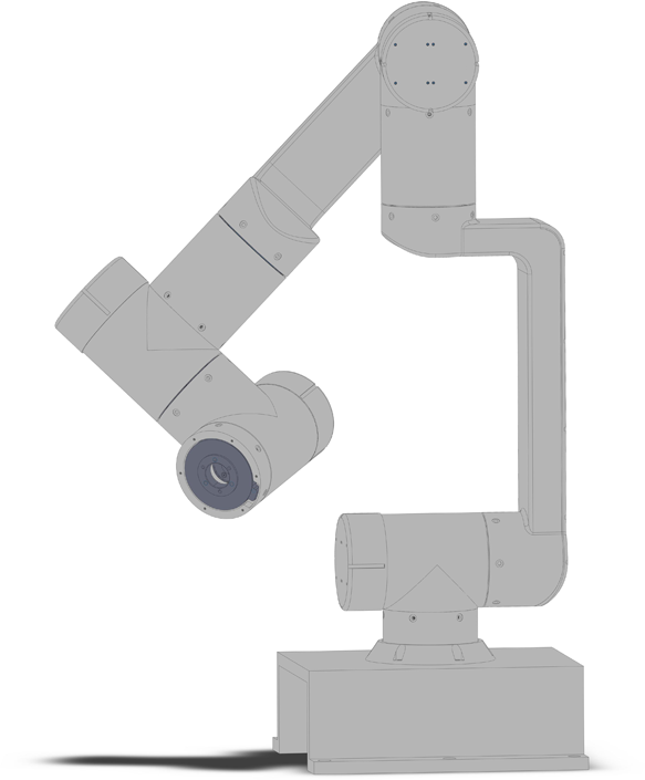
In this paper, a 7-DOF modular manipulator, which is shown in Fig. 1, is studied. According to its configuration, the angle of the seventh joint is considered a redundancy parameter to find the inverse kinematics solution of the manipulator. That is, for a specific tip pose, if
 $\theta _{7}$
is given, a finite number of collision-free analytical solutions for the remaining 6-DOF subchain can be found. The work of this section mainly provides the basis for the concept of the self-motion space, which is discussed in Section 3.
The modular manipulator studied in this paper.

2.1. Kinematics model and analysis
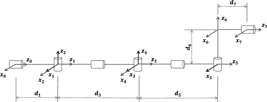
First, as indicated in Fig. 2, the kinematics model of the manipulator is established using the modified Denavit–Hartenberg (D–H) method [Reference Craig28].
The initial D-H model of the modular manipulator.

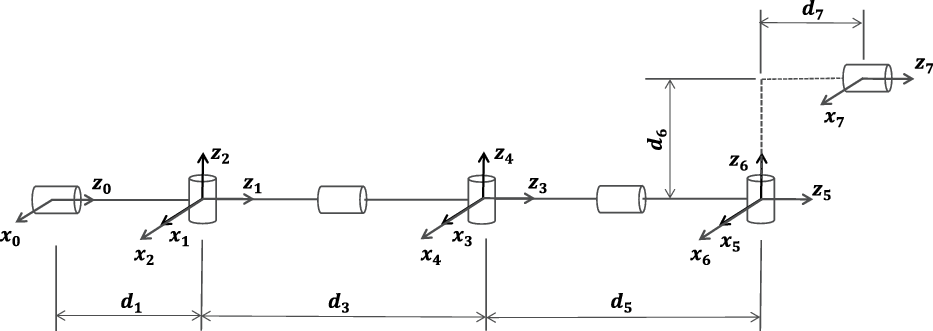
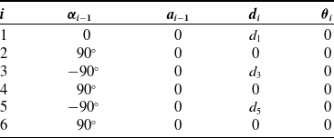
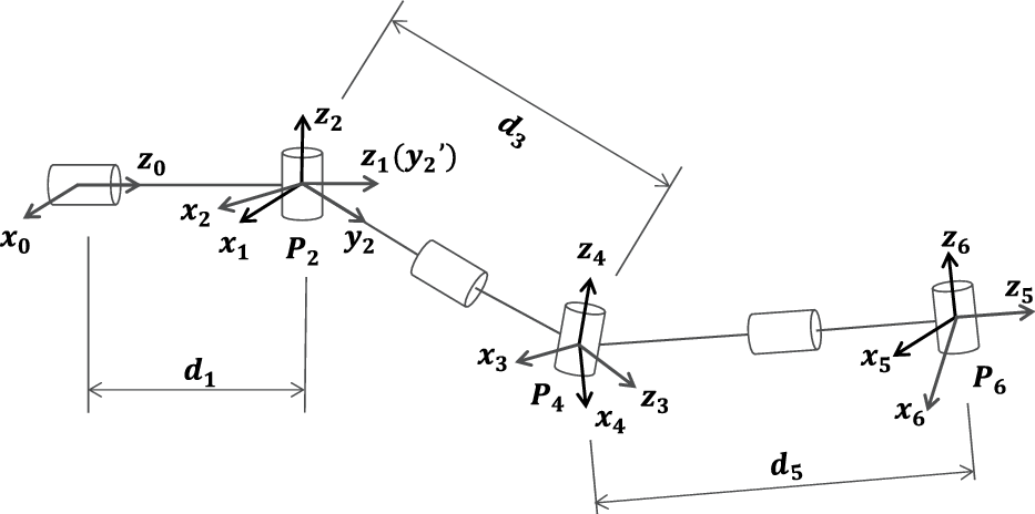
In order to simplify the calculation of the 6-DOF subchain, the kinematic modelling is improved, as shown in Fig. 3, and its D–H parameters are shown in Table I.
The improved D-H model.

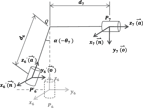
According to the configuration of the manipulator in Fig. 4, the link
 ${QP}_{7}$
is always perpendicular to the link
 $QP_{6}$
. For a specific tip pose
 ${ }_{7}^{0} T$
, if
 $\theta _{7}$
is given, it is equivalent to the rotation by an angle
 $\alpha$
of the link
 $QP_{6}$
around the axis
 $\mathord{\buildrel{\lower 3pt\hbox{$\scriptscriptstyle \rightharpoonup $}} \over z} _7$
. At this time, the 6-DOF subchain corresponds to a new tip pose
 ${}_6^0T^{\prime }$
, where
 \begin{equation} { }_{7}^{0} T=\left (\begin{array}{c@{\quad}c@{\quad}c@{\quad}c}{\mathord{\buildrel{\lower 3pt\hbox{$\scriptscriptstyle \rightharpoonup $}} \over n}} &{\mathord{\buildrel{\lower 3pt\hbox{$\scriptscriptstyle \rightharpoonup $}} \over o}} &{\mathord{\buildrel{\lower 3pt\hbox{$\scriptscriptstyle \rightharpoonup $}} \over a}} &{\mathord{\buildrel{\lower 3pt\hbox{$\scriptscriptstyle \rightharpoonup $}} \over P}_7} \\[5pt] 0 & 0 & 0 & 1\end{array}\right ), \end{equation}
 \begin{equation} {}_6^0T' = \left ({\begin{array}{c@{\quad}c@{\quad}c@{\quad}c}{\mathord{\buildrel{\lower 3pt\hbox{$\scriptscriptstyle \rightharpoonup $}} \over{{n}^{\prime }}}} &{\mathord{\buildrel{\lower 3pt\hbox{$\scriptscriptstyle \rightharpoonup $}} \over{{o}^{\prime }}}} &{\mathord{\buildrel{\lower 3pt\hbox{$\scriptscriptstyle \rightharpoonup $}} \over{{a}^{\prime }}}} &{\mathord{\buildrel{\lower 3pt\hbox{$\scriptscriptstyle \rightharpoonup $}} \over{{P}_{6}^{\prime }}}} \\[5pt] 0 & 0 & 0 & 1 \end{array}} \right ){{ = }}\left [{\begin{array}{c@{\quad}c@{\quad}c@{\quad}c}{n}_{x}^{\prime }&{o}_{x}^{\prime }&{a}_{x}^{\prime }&{p}_{x}^{\prime }\\[5pt] {n}_{y}^{\prime }&{o}_{y}^{\prime }&{a}_{y}^{\prime }&{p}_{y}^{\prime }\\[5pt] {n}_{z}^{\prime }&{o}_{z}^{\prime }&{a}_{z}^{\prime }&{p}_{z}^{\prime }\\[5pt] 0&0&0&1 \end{array}} \right ]. \end{equation}
We can rotate
 ${\mathord{\buildrel{\lower 3pt\hbox{$\scriptscriptstyle \rightharpoonup $}} \over z}_6}$
by an angle
 $\alpha$
around
 ${\mathord{\buildrel{\lower 3pt\hbox{$\scriptscriptstyle \rightharpoonup $}} \over z}_7}$
to obtain
 ${\mathord{\buildrel{\lower 3pt\hbox{$\scriptscriptstyle \rightharpoonup $}} \over{{a}^{\prime }}}}$
:
 \begin{equation} {\mathord{\buildrel{\lower 3pt\hbox{$\scriptscriptstyle \rightharpoonup $}} \over{{a} ^{\prime }}}} = {{{\mathord{\buildrel{\lower 3pt\hbox{$\scriptscriptstyle \rightharpoonup $}} \over z} }}_6}{\cos }\alpha + (1 - \cos \alpha )(\mathord{\buildrel{\lower 3pt\hbox{$\scriptscriptstyle \rightharpoonup $}} \over a} \cdot{{{\mathord{\buildrel{\lower 3pt\hbox{$\scriptscriptstyle \rightharpoonup $}} \over z} }}_6}) \cdot \mathord{\buildrel{\lower 3pt\hbox{$\scriptscriptstyle \rightharpoonup $}} \over a} + (\mathord{\buildrel{\lower 3pt\hbox{$\scriptscriptstyle \rightharpoonup $}} \over a} \times{{{\mathord{\buildrel{\lower 3pt\hbox{$\scriptscriptstyle \rightharpoonup $}} \over z} }}_6})\sin \alpha . \end{equation}
Since
 $\mathord{\buildrel{\lower 3pt\hbox{$\scriptscriptstyle \rightharpoonup $}} \over{{o} ^{\prime }}}$
is always parallel to
 $\mathord{\buildrel{\lower 3pt\hbox{$\scriptscriptstyle \rightharpoonup $}} \over a}$
,
 \begin{equation} {\mathord{\buildrel{\lower 3pt\hbox{$\scriptscriptstyle \rightharpoonup $}} \over{{o} ^{\prime }}}}={\mathord{\buildrel{\lower 3pt\hbox{$\scriptscriptstyle \rightharpoonup $}} \over a}}, \end{equation}
 \begin{equation} {\mathord{\buildrel{\lower 3pt\hbox{$\scriptscriptstyle \rightharpoonup $}} \over{{n} ^{\prime }}}}={\mathord{\buildrel{\lower 3pt\hbox{$\scriptscriptstyle \rightharpoonup $}} \over{{a} ^{\prime }}}} \times{\mathord{\buildrel{\lower 3pt\hbox{$\scriptscriptstyle \rightharpoonup $}} \over{{o} ^{\prime }}}}, \end{equation}
 \begin{equation} P_{6}^{\prime }=P_{7}-d_{7}{\mathord{\buildrel{\lower 3pt\hbox{$\scriptscriptstyle \rightharpoonup $}} \over a}} -d_{6}{\mathord{\buildrel{\lower 3pt\hbox{$\scriptscriptstyle \rightharpoonup $}} \over{{a} ^{\prime }}}}. \end{equation}
The transformation matrix of each link in the 6-DOF subchain can be obtained from the D–H parameters, and the kinematic equation is
 \begin{equation} { }_{6}^{0} T^{\prime }={ }_{1}^{0} T_{2}^{1} T_{3}^{2} T_{4}^{3} T_{5}^{4} T_{6}^{5} T. \end{equation}
Since there are three joint axes of the 6-DOF subchain intersecting at one point, which satisfies the Pieper criterion [Reference Siciliano, Khatib and Kröger29], the 6-DOF manipulator must have finite analytical solutions.
The D-H parameters of the 6-DOF subchain.

In order to study the influence of the redundancy angle on the tip pose of the 6-DOF subchain, we give the geometric relationship between the seventh and sixth joints.

2.2. Analytical method for
 $\theta _{4}$
,
$\theta _{6}$
and
$\theta _{1}$


First, we use the analytical method to solve the expressions for the sixth joint and the first joint of the 6-DOF subchain. Here, we refer to a method proposed by Raghavan and Roth [Reference Raghavan and Roth30]. By left-multiplying both sides of Eq. (7) by
 ${}_2^1{T^{-1}}{}_1^0{T^{-1}}$
and right-multiplying both sides of Eq. (7) by
 ${}_6^5{T^{-1}}$
, we can obtain
 \begin{equation} {}_2^1{T^{-1}}{}_1^0{T^{-1}}{}_6^0{T^{\prime }}{}_6^5{T^{ - 1}} ={}_3^2T{}_4^3T{}_5^4T. \end{equation}
Assuming that the first three elements of the fourth column on the left and right sides of Eq. (8) are column vectors
 $\mathord{\buildrel{\lower 3pt\hbox{$\scriptscriptstyle \rightharpoonup $}} \over P} _l$
and
 $\mathord{\buildrel{\lower 3pt\hbox{$\scriptscriptstyle \rightharpoonup $}} \over P} _r$
, respectively, if we let
 ${\mathord{\buildrel{\lower 3pt\hbox{$\scriptscriptstyle \rightharpoonup $}} \over P} _l}^2 ={\mathord{\buildrel{\lower 3pt\hbox{$\scriptscriptstyle \rightharpoonup $}} \over P} _r}^2$
, we can obtain
 \begin{equation} c_4 = \frac{{{{(p_z^{\prime } -{d_1})}^2} + p{{_x^{\prime }}^2} + p{{_y^{\prime }}^2} -{d_3}^2 -{d_5}^2}}{{2{d_3}{d_5}}}, \end{equation}
 \begin{equation}{\theta _4} = \pm \arccos\!(c_4). \end{equation}
Assuming that the first three elements of the third column on the left and right sides of Eq. (8) are column vectors
 $\mathord{\buildrel{\lower 3pt\hbox{$\scriptscriptstyle \rightharpoonup $}} \over I} _l$
and
 $\mathord{\buildrel{\lower 3pt\hbox{$\scriptscriptstyle \rightharpoonup $}} \over I} _r$
, respectively, if we let
 ${\mathord{\buildrel{\lower 3pt\hbox{$\scriptscriptstyle \rightharpoonup $}} \over R} _l} \cdot{\mathord{\buildrel{\lower 3pt\hbox{$\scriptscriptstyle \rightharpoonup $}} \over I} _l} ={\mathord{\buildrel{\lower 3pt\hbox{$\scriptscriptstyle \rightharpoonup $}} \over R} _r} \cdot{\mathord{\buildrel{\lower 3pt\hbox{$\scriptscriptstyle \rightharpoonup $}} \over I} _r}$
, we can obtain
 \begin{equation} \begin{array}{l} [(p_z^{\prime } -{d_1})o_z^{\prime } + p_x^{\prime }o_x^{\prime } + p_y^{\prime }o_y^{\prime }]c_6 + [(p_z^{\prime } -{d_1})n_z^{\prime } + p_x^{\prime }n_x^{\prime } + p_y^{\prime }n_y^{\prime }]s_6 ={d_5} +{d_3}c_4. \end{array} \end{equation}
We can use triangle substitution to obtain
 \begin{equation} \begin{array}{l}{\theta _6} = {\rm{atan2}}(N,\pm \sqrt{{M_1}^2 +{M_2}^2 -{N^2}} ) -{\rm{atan2}}({M_1},{M_2}),\\[5pt] {M_1} = (p_z^{\prime } -{d_1})o_z^{\prime } + p_x^{\prime }o_x^{\prime } + p_y^{\prime }o_y^{\prime },\\[5pt] {M_2} = (p_z^{\prime } -{d_1})n_z^{\prime } + p_x^{\prime }n_x^{\prime } + p_y^{\prime }n_y^{\prime },\\[5pt] N ={d_5} +{d_3}c_4. \end{array} \end{equation}
Let the elements of (3,3) and (3,4) of the left and right sides of Eq. (8) be equal, respectively:
 \begin{equation} - (p_y^{\prime }c_1 - p_x^{\prime }s_1) ={d_5}s_3s_4, \end{equation}
 \begin{equation} - (o_y^{\prime }c_6c_1 + n_y^{\prime }s_6c_1 - o_x^{\prime }c_6s_1 - n_x^{\prime }s_6s_1) = s_3s_4. \end{equation}
By substituting Eq. (14) into Eq. (13), the following equation can be obtained:
 \begin{equation} ({d_5}o_y^{\prime }c_6 +{d_5}n_y^{\prime }s_6 - p_y^{\prime })c_1 + ( \!-\!{d_5}o_x^{\prime }c_6 -{d_5}n_x^{\prime }s_6 + p_x^{\prime })s_1 = 0. \end{equation}
By triangle substitution,
 \begin{equation} \begin{array}{l}{\theta _1} ={\rm{atan2}}({R_1},{R_2}),\\[5pt] {R_1} ={d_5}o_y^{\prime }c_6 +{d_5}n_y^{\prime }s_6 - p_y^{\prime },\\[5pt] {R_2} = -{d_5}o_x^{\prime }c_6 -{d_5}n_x^{\prime }s_6 + p_x^{\prime }, \end{array} \end{equation}
where
 $\theta _{6}$
is related to
 $\theta _{1}$
; there are currently four sets of solutions.
2.3. Geometric method for
$\theta _{2}$
,
$\theta _{3}$
and
$\theta _{5}$


In Fig. 5, it can be seen from the configuration of the manipulator that the links
 ${P_2}{P_4}$
and
 ${P_4}{P_6}$
are always perpendicular to the axis
 $\mathord{\buildrel{\lower 3pt\hbox{$\scriptscriptstyle \rightharpoonup $}} \over z} _4$
, where the direction vectors of the links are expressed as
 $\mathord{\buildrel{\lower 3pt\hbox{$\scriptscriptstyle \rightharpoonup $}} \over r} _{24}$
and
 $\mathord{\buildrel{\lower 3pt\hbox{$\scriptscriptstyle \rightharpoonup $}} \over r} _{46}$
. Since
 $\mathord{\buildrel{\lower 3pt\hbox{$\scriptscriptstyle \rightharpoonup $}} \over r} _{46}$
is always equal to
 $\mathord{\buildrel{\lower 3pt\hbox{$\scriptscriptstyle \rightharpoonup $}} \over z} _5$
and
 $\theta _{6}$
has been obtained, by right-multiplying both sides of Eq. (7) by
 ${}_6^5{T^{ - 1}}$
, we can obtain
 \begin{equation}{}_6^0{T^{\prime }}{}_6^5{T^{ - 1}} ={}_1^0T{}_2^1T{}_3^2T{}_4^3T{}_5^4T ={}_5^0T, \end{equation}
where
 \begin{equation} {\mathord{\buildrel{\lower 3pt\hbox{$\scriptscriptstyle \rightharpoonup $}} \over z} _5} ={\mathord{\buildrel{\lower 3pt\hbox{$\scriptscriptstyle \rightharpoonup $}} \over r} _{46}} = [o_x^{\prime }c_6 + n_x^{\prime }s_6,o_y^{\prime }c_6 + n_y^{\prime }s_6,o_z^{\prime }c_6 + n_z^{\prime }s_6]^T, \end{equation}
 \begin{equation} {P_5} ={P_6} = [p_x^{\prime },p_y^{\prime },p_z^{\prime }]^T. \end{equation}
The geometric relations of the first six joints. When
 $\theta _{6}$
and
 $\theta _{1}$
are known, the corresponding values of the other four joint angles can be determined.

From Eq. (18) and Eq. (19), we can obtain
 \begin{equation}{P_2} = [0,0,{d_1}]^T, \end{equation}
 \begin{equation}{P_4} = -{d_5}{\mathord{\buildrel{\lower 3pt\hbox{$\scriptscriptstyle \rightharpoonup $}} \over r} _{46}} +{P_6}, \end{equation}
 \begin{equation}{\mathord{\buildrel{\lower 3pt\hbox{$\scriptscriptstyle \rightharpoonup $}} \over y} _2} ={\mathord{\buildrel{\lower 3pt\hbox{$\scriptscriptstyle \rightharpoonup $}} \over r} _{24}} = \frac{{{P_4} -{P_2}}}{{\left |{{P_4} -{P_2}} \right |}}. \end{equation}
When
 ${\theta _2} = 0$
,
 $\mathord{\buildrel{\lower 3pt\hbox{$\scriptscriptstyle \rightharpoonup $}} \over y} _2^{\prime } ={\mathord{\buildrel{\lower 3pt\hbox{$\scriptscriptstyle \rightharpoonup $}} \over z} _1} = [0,0,1]^T$
, and
 $\mathord{\buildrel{\lower 3pt\hbox{$\scriptscriptstyle \rightharpoonup $}} \over z} _2$
is always perpendicular to
 $\mathord{\buildrel{\lower 3pt\hbox{$\scriptscriptstyle \rightharpoonup $}} \over z} _1$
,
 $\mathord{\buildrel{\lower 3pt\hbox{$\scriptscriptstyle \rightharpoonup $}} \over y} _2^{\prime }$
and
 $\mathord{\buildrel{\lower 3pt\hbox{$\scriptscriptstyle \rightharpoonup $}} \over y} _2$
, so
 $\theta _{2}$
is the angle that
 $\mathord{\buildrel{\lower 3pt\hbox{$\scriptscriptstyle \rightharpoonup $}} \over y} _2^{\prime }$
rotates around
 $\mathord{\buildrel{\lower 3pt\hbox{$\scriptscriptstyle \rightharpoonup $}} \over z} _2$
to
 $\mathord{\buildrel{\lower 3pt\hbox{$\scriptscriptstyle \rightharpoonup $}} \over y} _2$
:
 \begin{equation} c_2 = \frac{{\mathord{\buildrel{\lower 3pt\hbox{$\scriptscriptstyle \rightharpoonup $}} \over y} _2^{\prime } \cdot{{\mathord{\buildrel{\lower 3pt\hbox{$\scriptscriptstyle \rightharpoonup $}} \over y} }_2}}}{{\left |{\mathord{\buildrel{\lower 3pt\hbox{$\scriptscriptstyle \rightharpoonup $}} \over y} _2^{\prime }} \right | \cdot \left |{{{\mathord{\buildrel{\lower 3pt\hbox{$\scriptscriptstyle \rightharpoonup $}} \over y} }_2}} \right |}}. \end{equation}
If
 $c_2 = 1$
, then
 $\mathord{\buildrel{\lower 3pt\hbox{$\scriptscriptstyle \rightharpoonup $}} \over y} _2^{\prime } ={\mathord{\buildrel{\lower 3pt\hbox{$\scriptscriptstyle \rightharpoonup $}} \over y} _2}$
, that is,
 ${\theta _2} = 0$
. If
 $c_2 \in (\!-\!1,1)$
, then it is necessary to determine whether
 $\mathord{\buildrel{\lower 3pt\hbox{$\scriptscriptstyle \rightharpoonup $}} \over y} _2^{\prime } \times{\mathord{\buildrel{\lower 3pt\hbox{$\scriptscriptstyle \rightharpoonup $}} \over y} _2}$
and
 $\mathord{\buildrel{\lower 3pt\hbox{$\scriptscriptstyle \rightharpoonup $}} \over z} _2$
point in the same direction. If they do, then
 ${\theta _2} = \arccos\!(c_2)$
; otherwise,
 ${\theta _2} = -\arccos\!(c_2)$
.
When
 ${\theta _4} \gt 0$
,
 $\theta _{4}$
is the angle that
 $\mathord{\buildrel{\lower 3pt\hbox{$\scriptscriptstyle \rightharpoonup $}} \over r} _{24}$
rotates around
 $\mathord{\buildrel{\lower 3pt\hbox{$\scriptscriptstyle \rightharpoonup $}} \over z} _4$
to
 $\mathord{\buildrel{\lower 3pt\hbox{$\scriptscriptstyle \rightharpoonup $}} \over r} _{46}$
; at this time, the axis of the fourth joint is
 \begin{equation}{\mathord{\buildrel{\lower 3pt\hbox{$\scriptscriptstyle \rightharpoonup $}} \over z} _{4 - 1}} = \frac{{{{\mathord{\buildrel{\lower 3pt\hbox{$\scriptscriptstyle \rightharpoonup $}} \over r} }_{24}} \times{{\mathord{\buildrel{\lower 3pt\hbox{$\scriptscriptstyle \rightharpoonup $}} \over r} }_{46}}}}{{\left |{{{\mathord{\buildrel{\lower 3pt\hbox{$\scriptscriptstyle \rightharpoonup $}} \over r} }_{24}} \times{{\mathord{\buildrel{\lower 3pt\hbox{$\scriptscriptstyle \rightharpoonup $}} \over r} }_{46}}} \right |}}. \end{equation}
Then,
 \begin{equation} c_3 = \frac{{{{\mathord{\buildrel{\lower 3pt\hbox{$\scriptscriptstyle \rightharpoonup $}} \over z} }_{4 - 1}} \cdot{{\mathord{\buildrel{\lower 3pt\hbox{$\scriptscriptstyle \rightharpoonup $}} \over z} }_2}}}{{\left |{{{\mathord{\buildrel{\lower 3pt\hbox{$\scriptscriptstyle \rightharpoonup $}} \over z} }_{4 - 1}}} \right | \cdot \left |{{{\mathord{\buildrel{\lower 3pt\hbox{$\scriptscriptstyle \rightharpoonup $}} \over z} }_2}} \right |}}. \end{equation}
If
 $c_3 = 1$
, then
 ${\mathord{\buildrel{\lower 3pt\hbox{$\scriptscriptstyle \rightharpoonup $}} \over z} _2} ={\mathord{\buildrel{\lower 3pt\hbox{$\scriptscriptstyle \rightharpoonup $}} \over z} _{4 - 1}}$
, that is,
 ${\theta _3} = 0$
. If
 $c_3 = 0$
, then
 ${\mathord{\buildrel{\lower 3pt\hbox{$\scriptscriptstyle \rightharpoonup $}} \over z} _2} = -{\mathord{\buildrel{\lower 3pt\hbox{$\scriptscriptstyle \rightharpoonup $}} \over z} _{4 - 1}}$
, that is,
 ${\theta _3}= \pi$
. If
 $c_3 \in (\!-\!1,1)$
, then it is necessary to determine whether
 ${\mathord{\buildrel{\lower 3pt\hbox{$\scriptscriptstyle \rightharpoonup $}} \over z} _2} \times{\mathord{\buildrel{\lower 3pt\hbox{$\scriptscriptstyle \rightharpoonup $}} \over z} _{4 - 1}}$
and
 $\mathord{\buildrel{\lower 3pt\hbox{$\scriptscriptstyle \rightharpoonup $}} \over r} _{24}$
point in the same direction. If they do, then
 ${\theta _3} = \arccos\!(c_3)$
; otherwise,
 ${\theta _3} = -\arccos\!(c_3)$
.
Now, we know
 $\mathord{\buildrel{\lower 3pt\hbox{$\scriptscriptstyle \rightharpoonup $}} \over r} _{46}$
,
 $\mathord{\buildrel{\lower 3pt\hbox{$\scriptscriptstyle \rightharpoonup $}} \over z} _6$
and
 $\mathord{\buildrel{\lower 3pt\hbox{$\scriptscriptstyle \rightharpoonup $}} \over z} _{4 - 1}$
;
 $\theta _5$
is the angle that
 $\mathord{\buildrel{\lower 3pt\hbox{$\scriptscriptstyle \rightharpoonup $}} \over z} _{4 - 1}$
rotates around
 $\mathord{\buildrel{\lower 3pt\hbox{$\scriptscriptstyle \rightharpoonup $}} \over r} _{46}$
to
 $\mathord{\buildrel{\lower 3pt\hbox{$\scriptscriptstyle \rightharpoonup $}} \over z} _6$
, so
 \begin{equation} c_5 = \frac{{{{\mathord{\buildrel{\lower 3pt\hbox{$\scriptscriptstyle \rightharpoonup $}} \over z} }_{4 - 1}} \cdot{{\mathord{\buildrel{\lower 3pt\hbox{$\scriptscriptstyle \rightharpoonup $}} \over z} }_6}}}{{\left |{{{\mathord{\buildrel{\lower 3pt\hbox{$\scriptscriptstyle \rightharpoonup $}} \over z} }_{4 - 1}}} \right | \cdot \left |{{{\mathord{\buildrel{\lower 3pt\hbox{$\scriptscriptstyle \rightharpoonup $}} \over z} }_6}} \right |}}. \end{equation}
If
 ${c_5} = 1$
, then
 ${\mathord{\buildrel{\lower 3pt\hbox{$\scriptscriptstyle \rightharpoonup $}} \over z} _6}={\mathord{\buildrel{\lower 3pt\hbox{$\scriptscriptstyle \rightharpoonup $}} \over z} _{4 - 1}}$
, that is,
 ${\theta _5}=0$
. If
 ${c_5}=0$
, then
 ${\mathord{\buildrel{\lower 3pt\hbox{$\scriptscriptstyle \rightharpoonup $}} \over z} _6} = -{\mathord{\buildrel{\lower 3pt\hbox{$\scriptscriptstyle \rightharpoonup $}} \over z} _{4 - 1}}$
, that is,
 ${\theta _5}=\pi$
. If
 $c_5 \in (\!-\!1,1)$
, then it is necessary to determine whether
 ${\mathord{\buildrel{\lower 3pt\hbox{$\scriptscriptstyle \rightharpoonup $}} \over z} _6} \times{\mathord{\buildrel{\lower 3pt\hbox{$\scriptscriptstyle \rightharpoonup $}} \over z} _{4 - 1}}$
and
 $\mathord{\buildrel{\lower 3pt\hbox{$\scriptscriptstyle \rightharpoonup $}} \over r} _{46}$
point in the same direction. If they do, then
 ${\theta _5}=\arccos\!(c_5)$
; otherwise,
 ${\theta _5} = - \arccos\!(c_5)$
.
When
 ${\theta _4} \lt 0$
, we can also obtain
 $\theta _3$
and
 $\theta _5$
using the above method.
It is worth noting that if we let the elements of (3,3) and (3,4) on both sides of Eq. (8) be equal, then
 \begin{equation} \begin{array}{l} - (p_y^{\prime }c_1 - p_x^{\prime }s_1) ={d_5}s_3s_4,\\[5pt] n_x^{\prime }c_1c_2s_6 + o_y^{\prime }s_1c_2c_6 + n_y^{\prime }s_1c_2s_6 + o_x^{\prime }c_1c_2c_6 + o_z^{\prime }s_2c_6 + n_z^{\prime }s_2s_6 = - c_3s_4. \end{array} \end{equation}
Since
 ${\theta _3}={\rm{atan2}} (s_3,c_3)$
, when
 $s_4= 0$
, the 6-DOF subchain is in a singular posture, and at this time,
 $\theta _3$
can take any value, and
 $\theta _6$
has only one solution. According to the geometric relationships of the manipulator, when
 $s_4 \ne 0$
, the value of
 $\theta _3$
is related to the value of
 $\theta _4$
. If, in this case, we use Eq. (27) to find
 $\theta _3$
, this will result in fewer solutions than normal.
Above all, when
 $s_4\ne 0$
, there are four groups of analytical solutions of the 6-DOF subchain.
3. The self-motion space about the redundancy angle
In this section, we will introduce the concept of the self-motion space. By rotating the seventh axis within its joint limit, the corresponding continuous intervals with collision-free analytical solutions can be obtained: they are called the self-motion spaces of
 $\theta _{7}$
for the current tip pose, the remaining unsolvable intervals are called the non-self-motion spaces. If we discretise the redundancy angle, we can also obtain the approximate self-motion spaces in which the 6-DOF subchain corresponding to any
 $\theta _{7}$
will almost always have at least one set of analytical solution.
3.1. The self-motion space of the tip pose
For a specific tip pose, we divide the rotation range of
 $\theta _7$
into
 $n_s$
parts and calculate how many sets of analytical solutions without collisions exist for each
 $\theta _7$
to obtain the feasible ranges of
 $\theta _7$
, approximately. We call these the self-motion spaces about
 $\theta _7$
for this tip pose. In the workspace of the manipulator, we randomly select 500 tip poses and calculate the self-motion spaces about
 $\theta _7$
for each of them, where
 ${n_s} = 360$
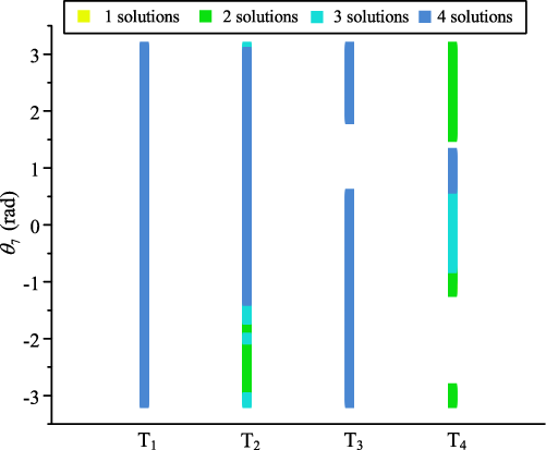
. Four representative self-motion spaces are selected, as shown in Fig. 6.
 $T_1$
–
 $T_4$
are four representative tip poses.

It can be seen that for
 $T_1$
and
 $T_2$
, the rotational limit of the seventh joint is all of the self-motion space of
 $\theta _7$
, but there are less than four sets of analytical solutions in the self-motion space of
 $T_2$
, which due to the self-collision of the manipulator configurations corresponding to some sets of analytical solutions. For
 $T_3$
and
 $T_4$
, only a few parts of the rotational limit of the seventh joint are self-motion spaces, and the distribution of the number of analytical solutions is not the same. Moreover, we find that the selectivity of the solution in the self-motion spaces of
 $T_2$
and
 $T_4$
is obviously inferior to that of
 $T_1$
and
 $T_3$
.
3.2. The self-motion space of the trajectory
For trajectory planning in Cartesian space, if the fixed trajectory is interpolated by countless tip poses and the self-motion spaces of all tip poses about
 $\theta _7$
are obtained, the self-motion spaces of the whole fixed trajectory about
 $\theta _7$
can be acquired; they are called the self-motion spaces of the trajectory about the redundancy angle. In fact, we can only interpolate the trajectory according a certain time interval, the self-motion spaces available are only approximately connected. However, we can also find a reasonable path along the time axis about the redundancy angle from them, which will guide us to continuous and collision-free solutions of the fixed trajectory.
In order to study the self-motion space of the trajectory, we randomly generate 120 straight trajectories in the workspace of the manipulator; each of these trajectories has a length of 0.3 m, and the movement time is 6 s. Their starting orientations are random, but all ending orientations are obtained by rotating 60
 $^\circ$
around the trajectory axis. These trajectories have a common feature, that is, without considering self-collision, if a reasonable initial seed is given at the starting tip pose, a set of feasible solutions of the trajectory will be found using a numerical method; this makes it convenient for us to explore how to plan a new set of feasible solutions of Cartesian trajectories when obstacles appear, which is further discussed in Section 4.
We choose four representative trajectories for the next analysis. A cubic polynomial is used to interpolate the tip poses of the trajectory with a time interval of 5 ms, and 1201 interpolated tip poses are obtained. In order to lower the computational cost of determining the self-motion spaces, we do not calculate the self-motion spaces for all interpolated tip poses. Instead, we find the self-motion space of the tip pose every
 $m-1$
tip poses from the initial moment; then, we can obtain
 $n+1$
self-motion spaces of the tip poses on the trajectory, where
 $m\cdot n+1=1201$
. We set
 $n=30$
,
 $m=40$
and
 $n_{s}=360$
, and we will discuss the reasons for setting these parameters in Section 4.
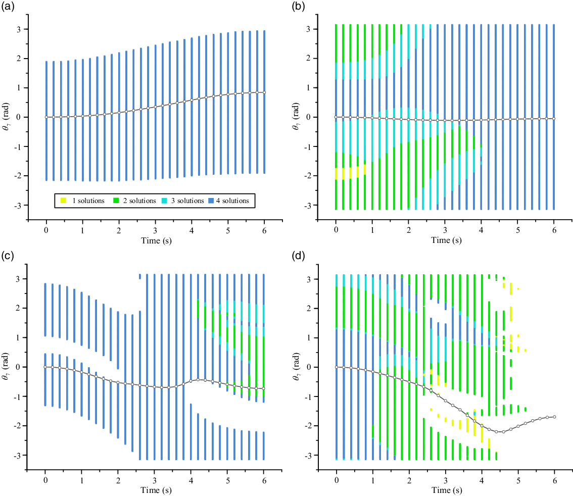
The self-motion spaces of the four trajectories are shown in Fig. 7. The inverse kinematics solutions of all interpolated tip poses of these trajectories are obtained using a numerical method, and the variations of theri
 $\theta _7$
are also shown in Fig. 7. Although the self-motion space in Fig. 7(a) is not full of the rotation limit of the seventh joint of the trajectory, there are four solutions for the 6-DOF subchain corresponding to any
 $\theta _7$
in the whole self-motion space. Although the self-motion space in Fig. 7(b) is full of the seventh joint limit of the trajectory, there are less than four sets of solutions in some regions, which is due to the self-collision of the configuration of some solutions (This situation is reflected in Fig. 7(c) and (d)). Some non-self-motion spaces are caused by the configuration constraints of the manipulator, and there are four sets of solutions in their adjacent self-motion spaces (This is particularly evident by the curve of
 $\theta _7$
in Fig. 7(c)). Other non-self-motion spaces are due to the self-collision of the configurations, as shown in Fig. 7(d) . We can roll the joint limit space of the trajectory around the time axis into a thin-walled cylinder, which enables us to understand the reachability of the seventh joint rotation more vividly.
The self-motion spaces of four representative trajectories,
 $\theta _{7}$
of these trajectories vary with time.

We can discover that the curves of
 $\theta _7$
do exist in the self-motion spaces of the corresponding trajectories in Fig. 7(a)–(c), but this case does not appear in Fig. 7(d), which is due to the self-collision in the latter half of the trajectory. In fact, in the case in which the trajectory of the redundancy angle is unchanged, the minimum number of solutions on the curve of
 $\theta _7$
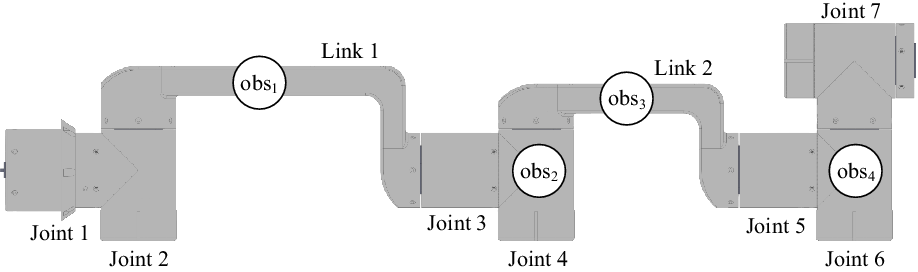
determines how many sets of solutions exist on the trajectory of the end effector. If there is an obstacle in the space occupied by the manipulator at any moment on the trajectory, the motion, according to the original solution set of the trajectory (Fig. 10(a)), will lead to the collision of the manipulator and the obstacle. Next, the influence of obstacles on the self-motion space of trajectory will be studied. We choose the Cartesian trajectory in Fig. 7(b) as a research object; considering the corresponding posture of the original solution set at 3 s as an example, spherical obstacles with diameters of 50 mm are added at four positions in the manipulator structure, respectively. The distribution of these obstacles is shown in Fig. 8, and the corresponding self-motion spaces are shown in Fig. 9.
Spherical obstacles are added at four positions in the manipulator structure; they are referred to as
 $obs_1$
,
 $obs_2$
,
 $obs_3$
and
 $obs_4$
, respectively. The geometric centres of
 $obs_2$
and
 $obs_4$
are located in the geometric centres of joint 4 and joint 6, and the geometric centres of
 $obs_1$
and
 $obs_3$
are located in the geometric centres of the upper rectangular envelopes of link 1 and link 2.

The self-motion spaces of the trajectory in Fig. 7(b) after adding different spherical obstacles.

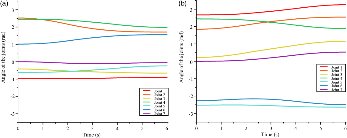
(a) The inverse kinematics solutions of seven joints of the manipulator obtained using a numerical method, where the change in the seventh axis is consistent with that in Fig. 7(b). (b) Under the condition that the
 $\theta _{7}$
curve in Fig. 7(b) is invariant, another set of collision-free inverse kinematics solutions of the trajectory is given after adding
 $obs_2$
.

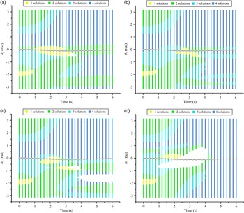
Looking at Fig. 9(a)–(c), we can see that the appearance of the obstacle hardly changes the range of the original self-motion space, but the number of solutions corresponding to some redundancy angle
 $\theta _7$
is reduced, because the emergence of obstacles causes some solutions to become invalid due to collisions. Nevertheless, the original trajectory of the redundancy angle is still in the self-motion space. In fact, a new set of non-collision solutions for the trajectory of the end effector can quickly be acquired by selecting another set of inverse solutions. Considering obs
2 as a case study, the variation of all seven joints of the manipulator is shown in Fig. 10(b), which is different from Fig. 10(a). In Fig. 9(d), however, there is a missing region in the middle of the self-motion space, which indicates that part of the original trajectory of
 $\theta _7$
is not in the self-motion space. This is because the presence of obs
4 directly reduces the limit of the redundancy angle, and all four solutions corresponding to the redundancy angle vanish. Therefore, in this case, a path-planning algorithm needs to be used to discover new paths.
As a matter of fact, no matter what distribution the self-motion space of the end effector’s trajectory has, as long as there is a transversely connected region, the following path-planning algorithm essentially finds a path in the self-motion space of the end effector’s trajectory, and every value of
 $\theta _7$
on the path corresponds to collision-free inverse solutions.
4. Path planning method in the self-motion space
We have now obtained the self-motion space of the end effector’s trajectory, which is similar to a two-dimensional map with obstacles. Therefore, a path-planning method for the self-motion space can refer to path-planning methods for a two-dimensional scene, but there are also differences between these two scenes. The moment corresponding to the path point in the former scenario is unique, and its path direction is singular along the time axis. Many previous research results can provide some enlightenment: for example, the rapidly exploring random tree algorithm [Reference LaValle31–Reference Gammell, Srinivasa and Barfoot34] can avoid obstacles and efficiently solve the problem of discovering paths with complex constraints. Nevertheless, the self-motion space of the trajectory of the end effector is usually complex. If the redundancy angles at the start and end time are not selected properly, a feasible path may not be discovered. The probabilistic roadmaps (PRM) algorithm [Reference Kavraki, Svestka, Latombe and Overmars35–Reference Missiuro and Roy38] is divided into a learning stage and a query stage. Its core idea is to randomly generate a series of nodes, including the start node and the goal node, in the configuration space and then connect these nodes to form a PRM. Finally, a feasible path from the start node to the goal node is found in the roadmap. If we refer to the ideas of the PRM algorithm to generate nodes in the self-motion space of the tip pose at each moment, determining whether the adjacent nodes can be connected and generating the data structure called the roadmap, which is represented by
 $R$
, then we can find a feasible path through the roadmap in the query stage.
4.1. Node generation stage
The roadmap that we obtain is a directed graph. For the self-motion space of the tip pose at a certain moment, we define the continuous self-motion spaces using road markings (
 $RM$
), which are obtained in the self-motion space generation stage; the points used to search in road markings are nodes (
 $N$
). In fact, we can roughly judge whether there is a connected region along the time axis using the range of the road markings at each moment. If the number of road markings at a certain moment is zero, this indicates that the self-motion space of the end effector’s trajectory is horizontally disconnected and the path planning fails. At the beginning of the node generation stage, we first make the midpoints of all road markings into nodes and connect nodes at any two adjacent moments to generate a local path. An average of
 $m - 1$
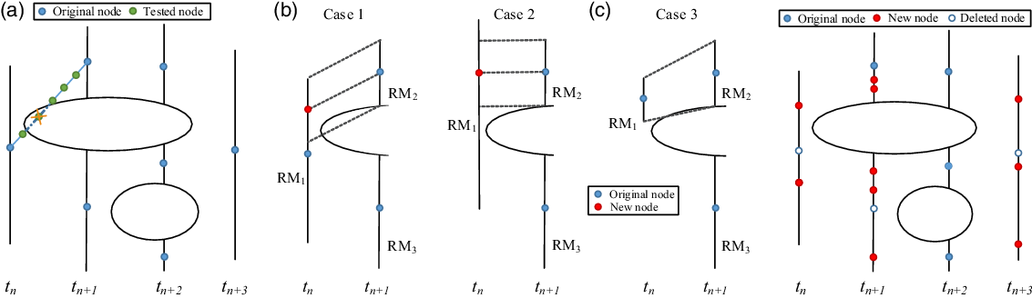
nodes to be detected are distributed on the local path to determine whether the local path is in the self-motion space. If it is, the local path information is stored in the roadmap. The local paths, of course, are not explicitly stored in the roadmap since recomputing them is very cheap. However, when the number of road markings at adjacent moments is different, connecting the nodes of two adjacent road markings may cause the algorithm to miss the connected region, as shown in Fig. 11(a). Therefore, in order to avoid the above situation, the road markings need to have more nodes.
(a) Schematic diagram that shows that the initial nodes may cause the algorithm to miss the connected region, (b) schematic diagram that shows three different cases in which more nodes are added and (c) schematic diagram that shows the node distribution after nodes are added to the road markings in panel (a).

As shown in Fig. 11(b), the number of road markings at the moment
 $t_n$
is less than that at
 $t_{n-1}$
;
 $R{M_1}$
and
 $R{M_2}$
are, respectively, road markings at
 $t_n$
and
 $t_{n-1}$
. When the range of
 $R{M_2}$
is smaller than that of
 $R{M_1}$
and
 $R{M_2} \not \subset R{M_1}$
, we project
 $R{M_2}$
to the nearest part of
 $R{M_1}$
and take the midpoint of the projection section as the new node of
 $R{M_1}$
; when the range of
 $R{M_2}$
is smaller than that of
 $R{M_1}$
and
 $R{M_2} \subseteq R{M_1}$
,
 $R{M_1}$
is horizontally projected onto
 $R{M_2}$
, and the midpoint of the projection section is taken as the new node of
 $R{M_1}$
. When the range of
 $R{M_2}$
is larger than that of
 $R{M_1}$
, the midpoint of
 $R{M_1}$
remains the node of
 $R{M_1}$
. For the road markings that generate new nodes, the original node, which is the midpoint of the road marking, needs to be deleted; for the road markings without additional nodes, the original unique nodes are retained. Figure 11(c) shows the situation after new nodes are added to all road markings.
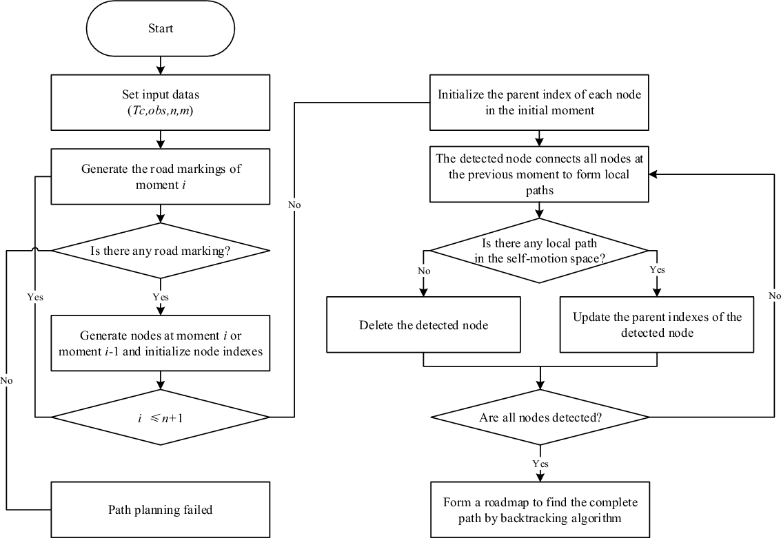
The algorithm framework of path planning of redundancy angle in the self-motion space.

In the node generation phase, the nodes at each moment are not generated using a randomised method, because random nodes make it easy to miss local connected regions, and the generation of more random nodes will greatly increase the amount of calculation required to generate the roadmap; thus, the method used to generate nodes in this paper is a compromise scheme, and the effect of this scheme in the experiments discussed later in this paper is ideal.
4.2. Roadmap generation stage
Since the path is unidirectional along the time axis, in the roadmap generation stage, the nodes at a certain moment only need to be connected to the nodes at the previous moment, and it is necessary to determine whether the local path is in the self-motion space of the end effector’s trajectory.
We describe the basic process of our algorithm by the algorithm framework in Fig. 12. In the input variables,
 $Tc$
represents the interpolation tip poses of the Cartesian trajectory. First, we calculate the self-motion spaces for each corresponding tip pose of
 $n+1$
moments, which is equivalent to obtaining the corresponding road markings. After generating nodes at each road markings (refer to the method in Fig. 11), each node stores an index, which indicates the position of this node in the self-motion space. The parent node information of every node represents the indices of its parent nodes. Before roadmap generation begins, we need to initialise the parent node information of the nodes at the initial moment. Next, each node at the current moment is connected to the node at the previous moment. If the local path is in the self-motion space, the index of the detected node at the previous moment is assigned to the parent index of the detected node at the current moment (one node may have multiple parent nodes). If the detected node cannot connect to all the nodes at the previous moment, this node will be deleted. When the nodes at the last moment complete the search, we can obtain the roadmap of the self-motion space, which contains all transversely connected regions in the self-motion space. By choosing any node at the end moment, we can find a feasible path in the roadmap.
4.3. Discussion on parameters
$n$
,
$m$
and
$n_s$


We define
 $r = m \cdot n \cdot n_s$
as the resolution of the self-motion space. Since our goal is to search for as many paths as possible in the self-moving space, it is beneficial for us to find as many connected regions as possible in the self-motion space through the roadmap. Suppose that there are at most
 $u$
connected regions in the self-motion space, the planner searches for
 $v$
connected regions at a certain resolution. If
 $v \neq u$
, it shows that the search effect is not ideal at this resolution, and the planning fails; if
 $v = u$
, the planning success.
In fact, the degree of discretisation of redundancy angle (
 $n_s$
) and the number of interpolation points of Cartesian trajectory (
 $m\cdot n$
) together determine the resolution
 $r$
. The higher the resolution is, the more likely it is that the planner will find the path if it does exist, and of course, it is more likely to find the disconnected local space. However, the improvement of the resolution will increase the computational cost of calculating the self-motion space of the trajectory. An increase in
 $n$
is mainly reflected in an increase in the number of detected moments and the number of nodes, while increasing
 $m$
will increase the number of detected nodes of the local path. However, the most critical problem is that we need not only to determine an appropriate ratio of
 $n$
and
 $m$
to ensure a high success rate of planning, of course, but also to consume as little computation as possible.
So we randomly generated 300 straight trajectories and added spherical obstacles such as obs
4 (refer to Section 3.2). The planner obtains the roadmap of each trajectory in six different
 $n$
and
 $m$
cases and calculates the number of their connected regions through the roadmap.
We can see that the planning success rate is the highest in the case of
 $n=30$
and
 $m=40$
, and the average time consumption is relatively small. Too small or too high the ratio of
 $n$
and
 $m$
is more likely to cause misjudgment of the connected region. Therefore, in this paper, setting
 $n=30$
and
 $m=40$
to study the effect of our algorithm is more reasonable.
Planning success rate and average planning time under different
 $m$
and
 $n$
.

4.4. Simulation
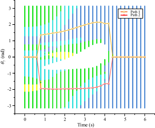
We performed experiments using the situation represented in Fig. 9(d) to verify our algorithm. Experiments were run on an Intel i5-7400 CPU with 8 GB of RAM. The processes of the algorithm take 9.17 s; the query time is so short that it can be ignored. After obtaining the roadmap, we only found two paths to analyse in the query stage. In fact, we can search all the paths in the roadmap using breadth-first search, but in practice, one of the appropriate paths can meet the obstacle avoidance requirements. As shown in Fig. 13, it seems that path 1 and path 2 are not smooth, and if we use cubic polynomials to interpolate these paths, there are large fluctuations in the curves of
 $\theta _{7}$
, and the same situation is reflected in other joints; this situation is not favourable for the control of the manipulator. If the rotational acceleration and velocity of the joints exceed the physical limits of the manipulator joints, this is obviously not realistic. In order to obtain the path with only a mild change, it is necessary to optimise the existing paths.
Two paths obtained in the query phase that represent two different connected regions in the self-motion space of the fixed trajectory.

The path planner also carried out path-planning simulation experiments on 119 other random trajectories. For 82 trajectories, the algorithm found feasible solvable paths and the average time consumption was 15.12 s. And for the other 38 trajectories, all planning failures occurred in the road-marking generation stage, and the average time consumption was 4.66 s, which is far less than that of planning successes.
5. Path optimisation and simulation
For a path obtained by the path-planning algorithm, there are
 $n+1$
path nodes on the path,
 $T$
is the motion time of the trajectory and the time interval between adjacent nodes is
 $\Delta t$
. For any moment
 $t$
, the path cost of the node at this moment is defined as
 \begin{equation} NC(t)=\left \{\!\begin{array}{c@{\quad}c} 2|\mathrm{path}(t)-\mathrm{path}(t+\Delta t)|, & t=0 \\[5pt] |\mathrm{path}(t)-\mathrm{path}(t-\Delta t)|+ |\mathrm{path}(t)-\mathrm{path}(t+\Delta t)|, & 0\lt t\lt T \\[5pt] 2|\mathrm{path}(t)-\mathrm{path}(t-\Delta t)|, & t=T \end{array}\right .\!\!\!. \end{equation}
The corresponding minimum path cost of the node is
 \begin{equation} NC_{\min }(t)=\left \{\!\begin{array}{c@{\quad}c} 0, & t=0 \\[5pt] \mathrm{path}(t+\Delta t)-\mathrm{path}(t-\Delta t)|, & 0\lt t\lt T \\[5pt] 0, & t=T \end{array}\right .\!\!\!. \end{equation}
The whole path cost is defined as
 \begin{equation} PC = \sum \limits _{i = 1}^n{\left |{\mathrm{path}({t_i}) - \mathrm{path}({t_{i - 1}})} \right |}. \end{equation}
At any moment
 $t$
, there is an interval
 $S_1$
in the self-motion space of the moment; the path cost of any node selected in this interval must be less than the path cost of the original node:
 \begin{equation}{\theta _\mathrm{mid}} = \left \{\! \begin{array}{c@{\quad}c}\mathrm{path}(t + \Delta t), & t = 0\\[5pt] \!\dfrac{{\mathrm{path}(t + \Delta t) - \mathrm{path}(t - \Delta t)}}{2}, & 0 \lt t \lt T\\[5pt] \mathrm{path}(t - \Delta t),& t = T \end{array} \right .\!\!,\end{equation}
 \begin{equation}{S_1} = \left \{\begin{array}{*{10}{l}} &[{2{\theta _\mathrm{mid}} - \mathrm{path}(t),\mathrm{path}(t)}],&\mathrm{path}(t) \ge{\theta _\mathrm{mid}}\\[5pt] &[{\mathrm{path}(t),2{\theta _\mathrm{mid}} - \mathrm{path}(t)}],&\mathrm{path}(t) \lt{\theta _\mathrm{mid}} \end{array} \right .\!\!. \end{equation}
When optimising the path node at moment
 $t$
, it is necessary to ensure that the new selected node is in the original road marking
 $S_2$
, so the optimisation space of
 $t$
is
 $S ={S_1} \cap{S_2}$
. For a certain moment, we randomly select a node in
 $S$
as a new path node to be checked. Similar to the path-planning algorithm, the new node is connected to the neighbouring node at the adjacent moment to generate one or two local paths. If they are in the self-motion space, this new path node is retained. However, before detection, if we determine that the path cost of the node is the minimum path cost, the path node optimisation process is omitted. The optimisation planner converges the path to a state with a low path cost through limited cycles.
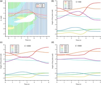
Results of optimising path 2 in Fig. 13 with different cycle numbers: (a) the three optimisation results of
 $\theta _{7}$
, and (b)–(d) the changes of the corresponding seven joints, respectively.

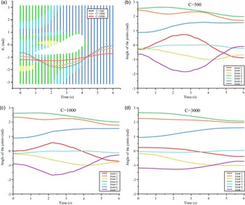
Results of optimising path 2 in Fig. 13 with different cycle numbers: (a) the three optimisation results of
 $\theta _{7}$
, and (b)–(d) the changes of the corresponding seven joints, respectively.

Of course, the degree of fluctuation of the whole path needs to be evaluated by the variance of all path nodes. We define the variance of the path as
 \begin{equation} PV = \frac{1}{n+1} \sum \limits _{i = 0}^n{\left |{\mathrm{path}({t_i}) - \mathrm{path}_\mathrm{avg}} \right |} \end{equation}
We optimise the two paths in Fig. 13 using 500, 1000 and 3000 cycles; the selection of the path node is random, and the number of cycles is represented by
 $C$
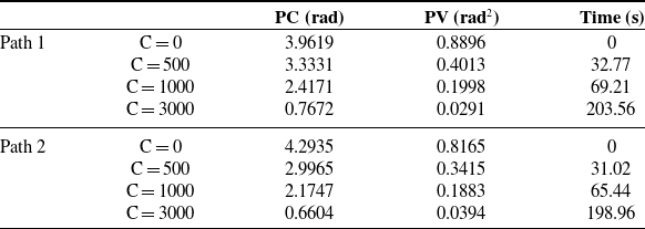
in the following figures and table. As shown in panel (a) of Figs. 14 and 15, as the number of optimisation cycles increases, the variation of the whole path tends to decrease, and
 $\theta _7$
at the start and end moments gradually approaches. The same trend is also confirmed by Table III: the cost and variance of all paths continue to decrease. Panels (a)–(b) of Figs. 14 and 15 exhibit the variation of other joints corresponding to the optimised paths; we can see that as the optimisation cycle number increases, the variation of each joint angle becomes smoother, and the range of the variation decreases. Since the rotation range of the sixth joint of the manipulator studied in this paper can exceed 360
 $^\circ$
, the angle of the joint 6 in Fig. 14(b)–(d) can exceed
 $\pi$
. In the research of our path optimisation method, some initial paths which are relatively smooth in the roadmap hardly need to be optimised. In other words, choosing a path with a minimum path cost and minimum variance from the roadmap can effectively reduce the optimisation time. For the optimised path, if the acceleration or velocity of some joints exceeds their performance limits, this problem can be solved by continuing to optimise the path or by extending the motion time of the trajectory appropriately, if the working conditions permit this.
6. Comparison with obstacle avoidance method based on GPM
As we discussed in Section 1, the obstacle avoidance problem of redundant manipulator is often solved based on GPM and the velocity deviation method is one of the classical methods [Reference Liu, Tong, Ju and Liu10, Reference Maciejewski and Klein11]. Maciejewski et al. proposed to set an desired escape velocity  on the links of the manipulator entering the obstacle safety zone, so that the manipulator moves away from the obstacle.

The first term in Eq. (34) can ensure the main motion of the end effector of the manipulator, and the second term makes the joints of the manipulator produce obstacle avoidance motion, so that the manipulator can obtain obstacle avoidance solution.
 $\boldsymbol{J}$
,
 $\boldsymbol{J}_c$
and
 $\boldsymbol{J}^{+}$
represent the Jacobian matrix of the end effector of the manipulator, the Jacobian matrix of the obstacle avoidance point of the manipulator (without considering rotation) and the the pseudo-inverse of the Jacobian matrix, respectively.
 represents the increment of joints per iteration. Since the influence of singularity on trajectory planning is not considered in this paper, it is reasonable to use Jacobian pseudo-inverse matrix. Moreover, the trajectory planning method based on self-motion space proposed in this paper is an offline planning method. Therefore, we also use GPM to plan obstacle avoidance trajectory offline.
The path cost, path variance and time consumption of origin paths and optimised paths.

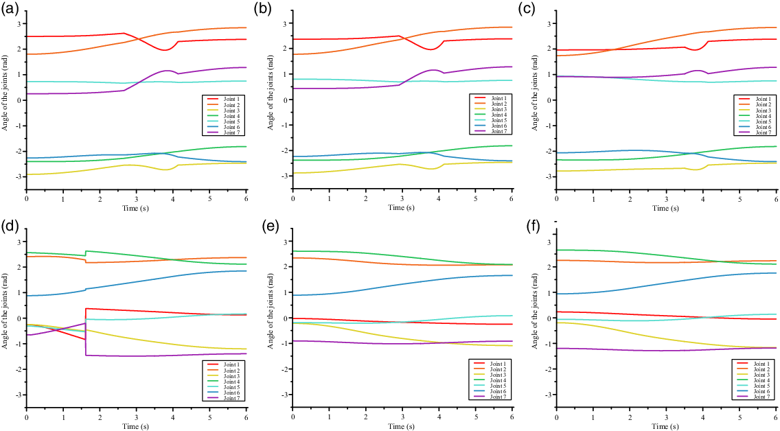
Trajectory planning results for the scenario in Fig. 9(d) using the obstacle avoidance method based on GPM, where (a)–(f) correspond to different initial seeds.

We consider simulating in the same obstacle environment as in Fig. 9(d) to compare with our method. The inverse solution of the initial tip pose in Fig. 14(b)–(d) and Fig. 15(b)–(d) is selected as the initial seed for GPM, and the calculated trajectory interpolation tip poses are 1201. We obtain six different sets of trajectory inverse solutions, as shown in Fig. 16.
It can be clearly seen in Fig. 16(a)–(c) that some joints have a sudden change in speed due to the influence of escape velocity
 , which is very unfavourable for the control of the manipulator. In fact, an oversized escape velocity can even cause the joints to shake continuously when near the obstable safety zone. Figure 16(d) shows that the obstacle avoidance trajectory planning fails, while our method can successfully plan the collision-free inverse solution of the trajectory, such as Fig. 15(b). For Fig. 16(e) and (f), similar to Fig. 15(d) have a good effect, but this is because the configuration of initial seed is far from the obstacle, in the process of performing trajectory planning, the links of the manipulator has never entered the obstacle safety zone, making the trajectory of each joint smoother. It can also be seen from this that the choice of initial seed has a great influence on the planning effect of GPM.
At the same time, for the 82 Cartesian trajectories in Section 4.4, which all have successful redundancy angle path planning, we refer to the above method for them to plan continuous collision-free inverse solutions. Among them, we only select a redundancy angle path in the roadmap for different number of path optimisation.
In Table IV, the average planning time of the proposed method in this paper includes redundancy angle path planning time and path optimisation time. As shown in Table IV, the obstacle avoidance trajectory planning based on self-motion space has a greater advantage in the success rate of planning, which can also be reflected in Fig 16 (the quality of the trajectory is also better). GPM has a certain advantage in planning time, but this advantage is not obvious when
 $C = 500$
. With the increase of the number of path optimisation, GPM obtains better initial seeds, so its planning success rate is improved.
Under different number of path optimisation, the number of successes and average planning time of the two obstacle avoidance planning methods.

By and large, the concept of self-motion space is proposed, which allows us to consider the trajectory planning problem from a global perspective. This not only means that we can get more diverse trajectory inverse solutions, which can increase the success rate of planning (including excluding the inverse solutions of Cartesian trajectories affected by singularity), but also means that we can get smoother trajectory inverse solutions through optimisation algorithm proposed, which is conducive to the control of manipulator joints. More importantly, since the collision information between the manipulator and the obstacles can be fully reflected in the self-motion space, the proposed method in this paper is not affected by multi-obstacle environments and complex configurations.
7. Conclusion
The concept of the self-motion space of the redundancy angle is proposed in this paper to describe the solvable configurations of the 7-DOF manipulator; then, we extend it to the self-motion space of a Cartesian-space trajectory, which helps us to understand the dextrous characteristics of a 7-DOF redundant manipulator. In fact, the self-motion space reflects the solvability of the manipulator at a given tip pose or given trajectory; a higher solvability means a higher obstacle-avoidance potential. Of course, it not only can be used to solve the obstacle avoidance problem for a fixed trajectory in Cartesian space but also provides a ‘map’ for selecting the inverse solution of the manipulator trajectory under specific requirements.
The path-planning algorithm proposed in this paper can effectively find a feasible connected region in the self-motion space of a fixed trajectory. We have generated as few nodes as possible on road markings at all moments to help generate roadmaps, and simulation experiments have proved that this method is effective. Due to the fact that the processes of determining the self-motion space, generating nodes and searching the roadmap are all offline, selecting the required paths through online queries is very quick. Of course, reducing the resolution of self-motion space appropriately can help us reduce the computational cost of path planning, which is also applicable to path optimisation.
Through the path optimisation algorithm, a smooth redundancy angle variation curve is obtained; at the same time, the path cost and path variance gradually decrease. The continuous collision-free solution set of the Cartesian trajectory can be found using the optimised path discussed above, allowing the precise control of the given Cartesian trajectory through a position-based control strategy. At the same time, compared with the obstacle avoidance method based on GPM, the method proposed in this paper has better advantages in the smoothness of joints’ trajectory and the diversity of inverse solutions.
Acknowledgments
The research leading to these results has received funding from the National Natural Science Foundation of China.
Author contributions
Yuan Quan, Ke Wang and Chong Zhao conceived and designed the study. Yuan Quan completed the algorithm research and implementation. Yuan Quan and Haifeng Zhao completed the experimental data analysis. Yuan Quan, Congmin Lv and Hongyu Lv wrote the article.
Financial support
This work was financially supported by the National Natural Science Foundation of China (52205039, 52105011, 52005183).
Conflicts of interest
The authors declare none.