1. Introduction
Upon impact of a vertical liquid jet with a solid horizontal surface, the liquid spreads radially on the surface. As a result, a sudden increase in the flow height occurs at a specific distance from the jet impact point; this abrupt rise of the fluid surface that converts a supercritical flow to a subcritical flow is known as a hydraulic jump. The vertical jet impinging on a solid surface is important in a variety of processes, such as aircraft generator coils, coating flows, impingement cooling of electronic devices, laser mirrors and material processing in manufacturing (Avedisian & Zhao Reference Avedisian and Zhao2000).
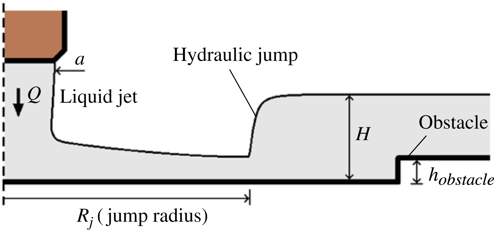
A schematic illustration of a circular hydraulic jump is shown in figure 1. A circular hydraulic jump is expected for a circular impinging jet; however, experiments indicate that the hydraulic jump may be formed wonderfully in non-circular shapes whereas the vertical jet is circular.
A schematic diagram of an impinging liquid jet onto a horizontal plate and the formation of the hydraulic jump in cylindrical coordinates.

The classical planar hydraulic jump, which occurs in open-channel flows, is a very old and well-known phenomenon thoroughly considered in the literature. The first person who encountered this phenomenon was Rayleigh (Reference Rayleigh1914). However, the hydraulic jumps that form on the target plate are different phenomena; these kinds of jumps can be divided into two main groups, circular and non-circular hydraulic jumps. Predicting the jump location and its behaviour is the most important issue for circular hydraulic jumps. Birkhoff & Zarantonello (Reference Birkhoff and Zarantonello1957) presented the complete theory of inviscid circular hydraulic jumps. From the inviscid theory, there is a balance between pressure force and momentum at the jump position. However, because of the thinness of the liquid layer, particularly before the jump, it is clear that the flow in such a problem is viscous and the inviscid theory is not appropriate for predicting the radius of the circular hydraulic jump. Watson (Reference Watson1964) was the first who considered the effect of viscosity on a circular hydraulic jump. He theorized this phenomenon by assuming the boundary layer principle for the upstream of the jump that expands from the hitting point of the liquid jet. Many different researchers throughout the world in the last four decades such as Watson himself, Craik et al. (Reference Craik, Latham, Fawkes and Gribbon1981), Errico (Reference Errico1986) and Liu & Lienhard (Reference Liu and Lienhard1993) have investigated the validity of Watson’s theory experimentally; they showed that Watson’s theory has little agreement with experimental results in some conditions. Bush & Aristoff (Reference Bush and Aristoff2003) studied the circular jump both experimentally and analytically, in which they considered the influence of surface tension; they modified Watson’s theory and indicated that surface tension may play an important role in creating a hydraulic jump.
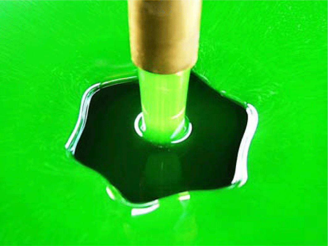
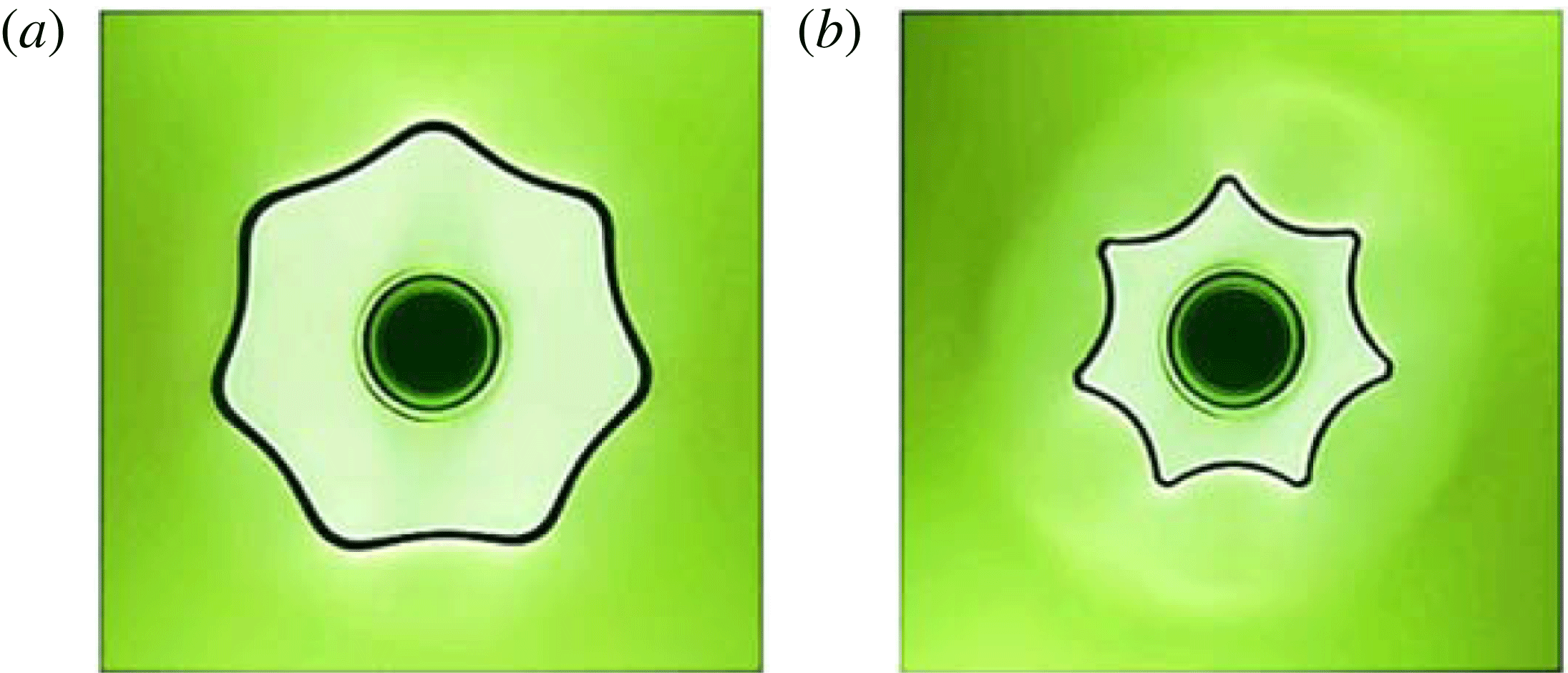
Non-circular hydraulic jumps formed by a viscous liquid (see figure 2) are an interesting phenomenon. Based on many laboratory studies, these jumps can be divided into polygonal and clover-shaped jumps. Ellegaard et al. (Reference Ellegaard, Hansen, Haaning, Hansen, Marcusson, Bohr, Hansen and Watanabe1999), who had already investigated the circular jump empirically, for the very first time, observed polygonal hydraulic jumps in their experiments. They discovered that stationary polygonal shapes can form when the fluid viscosity is high (approximately 11 times the viscosity of water). They revealed the dependence of the number of corners on the flow rate, nozzle height and downstream height for a nozzle with inner radius 0.5 cm in polygonal jumps and proposed a heuristic model.
A sample non-circular jump to form a stable hexagon. The working fluid is ethylene glycol.

Bush, Aristoff & Hosoi (Reference Bush, Aristoff and Hosoi2006) focused their laboratory studies on this field to achieve more results. In addition to the polygonal jumps, they displayed a new non-circular class in the form of clover-shaped jumps; higher-viscosity fluids (approximately 30 cS) are used to achieve this kind of hydraulic jump. Their results indicate the dependence of the shape of non-circular jumps, including polygonal and clover, on the jet diameter, downstream height, kinematic viscosity, surface tension and flow rate based on a few governing dimensionless groups.
Stability is an important factor for the classification of circular and non-circular hydraulic jumps. A number of factors such as downstream height, flow rate, viscosity, surface tension and gravity affect jump stability. Increasing the downstream height changes the steady jump structure into a time-dependent flow or even into a turbulent flow (Ellegaard et al. Reference Ellegaard, Hansen, Haaning and bohr1996). Raising the surface tension makes the jump unstable (Bush & Aristoff Reference Bush and Aristoff2003). There is a critical surface tension above which steady circular jumps do not exist, implying that a transition to either an unsteady circular jump or a non-circular jump may occur. This critical surface tension depends on viscosity, the flow rate and other parameters; and it decreases with the increase of viscosity, which might explain why polygonal jumps are observed only in highly viscous fluids (Kasimov Reference Kasimov2008). Bush et al. (Reference Bush, Aristoff and Hosoi2006) and Martens, Watanabe & Bohr (Reference Martens, Watanabe and Bohr2012) found that the instability in the circular jumps and the formation of non-circular ones can be related to the Rayleigh–Plateau instability. In addition, they proposed an empirical relationship for the wavelength of the instability of steady non-circular jumps based on surface tension, density and radial velocity. The multistability (hysteresis) of polygonal jumps is reported by Ellegaard et al. (Reference Ellegaard, Hansen, Haaning, Hansen, Marcusson, Bohr, Hansen and Watanabe1999), who mentioned that several polygons can be stable in a constant parameter regime, but they did not show which corner numbers may coexist at constant flow parameters.
In this study, the experimental observations of polygonal hydraulic jumps is presented. Stable polygonal jumps are studied and their phase diagrams are illustrated in both states of increasing and decreasing flow rate. A special region is defined as the region of stability for the polygonal jump. In addition, the jump sizes are reported and their dependence on related dimensionless groups is investigated. The inscribed and circumscribed circular radii of each polygon were measured in order to compare the various polygons together and to find a mean jump radius to compare with Watson’s theory. Also, a rare unstable polygonal jump – a rotational jump, which seems to be a new class of non-circular hydraulic jump – is presented.
2. Experimental set-up
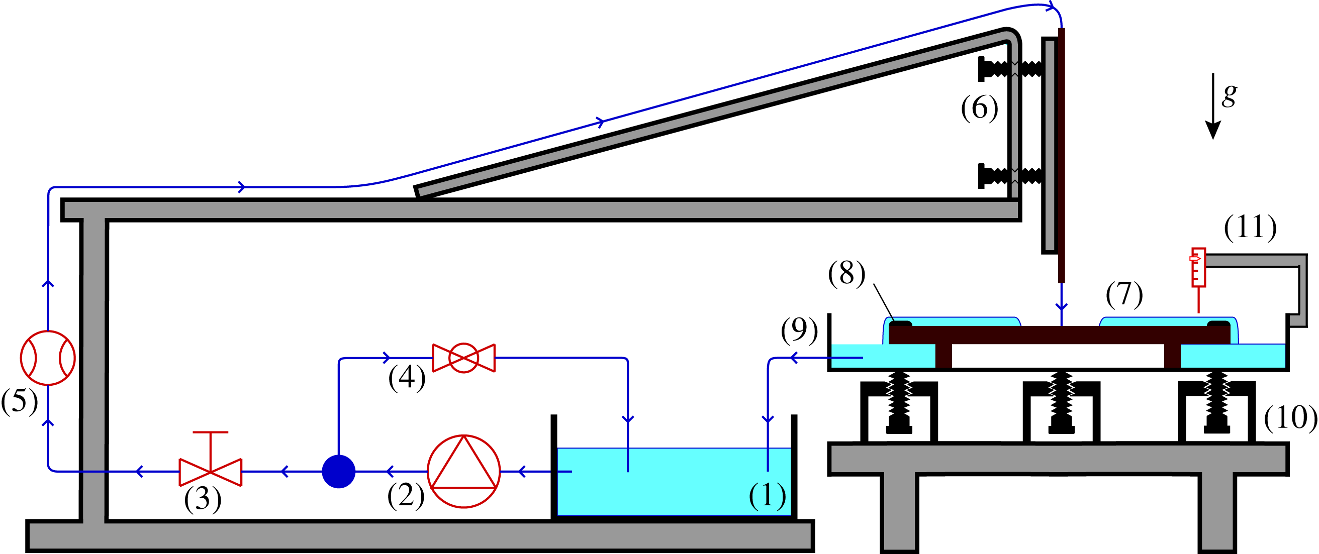
The experimental set-up used in this study is shown in figure 3. It contains a reservoir to hold the working fluid, a gear pump, pipes with different diameters (to achieve different jet radii), flow meter, some supporting fixtures, glass target plate, horizontal and vertical levelling mechanisms, liquid height measurement system, and also lighting and imaging mechanisms.
The schematic of the experimental set-up: (1) reservoir, (2) pump, (3) control valve, (4) bypass valve, (5) flow meter, (6) vertical levelling mechanism, (7) glass target plate, (8) obstacle (Plexiglas rim), (9) container, (10) horizontal levelling mechanism and (11) liquid film height measurement system (digital callipers).

We used ethylene glycol as the working fluid with density
 ${\it\rho}=1.1\ \text{kg}\ \text{m}^{-3}$
, viscosity
 ${\it\nu}=11.8\ \text{cS}$
and surface tension
 ${\it\sigma}=47.5\ \text{dyn}\ \text{cm}^{-1}$
. The working fluid was circulated by a pump that was capable of fluxes in the range of
 $0{-}200\ \text{ml}\ \text{s}^{-1}$
. The flow rate was adjusted by using two control valves located in the fluid flow path. Because of the high dependence of the polygonal hydraulic jump on the flow rate, high-sensitivity control valves were used.
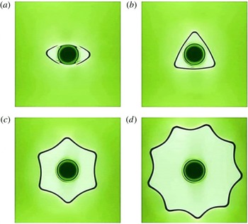
The pipes were long enough (approximately 90 cm) to achieve laminar and fully developed flow. The end part of the pipes was tapered in order to suppress turbulence, and they were fixed on an adjustable vertical support to have a vertical jet. By applying wide lighting above the target plate, the bottom and top parts of the hydraulic jumps were captured. Many of the polygonal jumps imaged from the bottom of the target plate are shown in figure 4. The black lines display the shadow of the place of the hydraulic jump.
In the experiments performed in this study, the distance between the nozzle (the pipe exit) and the target plate was 1 cm. The target plate over which the jump is formed had a diameter of 35 cm. The parameters adjusted in experiments were obstacle height, nozzle diameter and flow rate. Four Plexiglas rims with various thicknesses of 0.22, 0.3, 0.32 and 0.35 cm were used as obstacle. Rims were located on the glass target plate as shown in figure 3 to produce a proper downstream height, which plays an important role in forming the non-circular jumps. The different jet radii were created by applying tubes with radii of 0.250, 0.295, 0.345, 0.385 and 0.515 cm. A tiny deviation of the impact plate from the horizontal level and the liquid jet from the vertical made the jump irregular and asymmetric; consequently, great care was taken in levelling the target plate. Three adjustable supporting legs were used to level the target plate and its deflection was measured with a spirit level.
The stable polygonal jumps with (a) two, (b) three, (c) six and (d) nine corners, viewed from directly below through the impact glass plate. The jet radius exiting the nozzle is
 $a=0.515\ \text{cm}$
.

Beyond the hydraulic jump, the liquid ultimately filled the container that delivered it to the reservoir to complete the fluid flow loop. The pump was isolated to avoid transmission of vibrations into the vertical jet and horizontal plate in order to have a polygonal jump with minimal vibration.
A needle was joined to digital callipers vertically in order to measure the downstream height with an accuracy of 0.01 mm and the flow rate was also measured directly by using an electronic flow meter accurate to 0.1 % over the range considered. The sizes of the jumps were measured by a transparent ruler below the glass target plate. The digital images of this sizing were imported to a graphics editing program (Adobe Photoshop) to get precise dimensions of the jump.
3. Observations
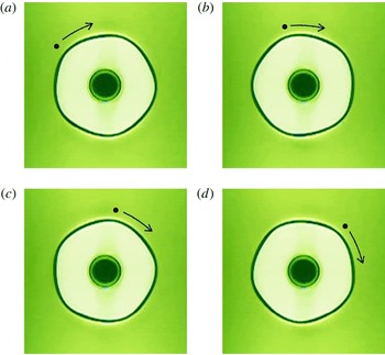
Circular hydraulic jumps are always formed at lower downstream height than non-circular jumps. By increasing the downstream height, the radius of a circular jump reduces (Passandideh-Fard, Teymourtash & Khavari Reference Passandideh-Fard, Teymourtash and Khavari2011) until the jump becomes unstable and somehow loses its circularity. Our experiments show that this circular jump oscillates by a rotational wave, which encompasses the whole jump. In this condition, the jump emerges as a type II jump with only one continuous surface roller, which has not yet been broken. The angular velocity of the wave is very high, approximately 50–100 r.p.m., as shown in figure 5. If the downstream height is increased further, the surface roller is broken and a stable polygonal jump is revealed. It seems that this behaviour can be related to Rayleigh–Plateau instability, introduced by Bush et al. (Reference Bush, Aristoff and Hosoi2006).
Rayleigh (Reference Rayleigh1879) and Plateau (Reference Plateau1873) indicated that a fluid thread is bounded by a surface force due to the surface tension and it becomes unstable in a certain condition in order to minimize surface energy. It seems that the waves that occur just before transformation of a circular jump into a polygonal jump are very similar to the mentioned instability. In fact, there is a certain parameter regime that makes a circular jump unstable and leads to a polygonal jump in which the surface tension probably plays the main role.
Wavelike instability on a circular hydraulic jump at (a)
 $0\ \text{s}$
, (b)
 $0.066\ \text{s}$
, (c)
 $0.133\ \text{s}$
and (d)
 $0.2\ \text{s}$
. Black dots are drawn at a specified corner. Here
 $a=0.515\ \text{cm}$
,
 $Q=44.8\ \text{ml}\ \text{s}^{-1}$
,
 $H=0.55\ \text{cm}$
and
 ${\it\omega}=76.62\ \text{r.p.m.}$

3.1. Stable polygonal hydraulic jumps
These types of non-circular hydraulic jumps are fixed, without any motion in their appearances; therefore, they were named stable jumps (figures 2 and 4).
Kasimov (Reference Kasimov2008) noted that there is a critical surface tension above which steady circular jumps do not exist, implying that a transition to either an unsteady circular jump or a non-circular jump may occur. This critical surface tension depends on viscosity and other governing parameters and it decreases with the increase of viscosity, which might explain why polygonal jumps are observed only in highly viscous liquids. The effect of surface tension also was investigated experimentally by Bush et al. (Reference Bush, Aristoff and Hosoi2006) and it was revealed that decreasing surface tension causes a polygonal jump to change to a circle. Our experiments indicated that the non-circular forms are created by ethylene glycol as the working fluid. Ethylene glycol has a viscosity approximately 13 times the viscosity of water and its surface tension is approximately two-thirds that of water. Many different factors, such as kinematic parameters (e.g. flow rate
 $Q$
), geometric parameters (e.g. downstream height
 $H$
and jet radius
 $a$
) and the physical properties of the fluid (e.g. viscosity
 ${\it\nu}$
, surface tension
 ${\it\sigma}$
and density
 ${\it\rho}$
), can affect the size, the number of corners and also the stability. The dimensionless groups used here are the Bond number
 $\mathit{Bo}={\it\rho}ga^{2}/{\it\sigma}$
, the jet Reynolds number
 $\mathit{Re}=Q/({\it\nu}a)$
and the jump Weber number
 $\mathit{We}={\it\rho}Q^{2}/({\it\sigma}H^{3})$
in accordance with recent studies (Bush et al.
Reference Bush, Aristoff and Hosoi2006). The Bond number consists of surface tension, density and jet radius; since the physical properties of the working liquid are constant, the Bond number will depend only on the jet radius. Accordingly, five different constant values for Bond number,
 $\mathit{Bo}=6.03$
, 3.36, 2.70, 1.98 and 1.4, were obtained in our experiments.
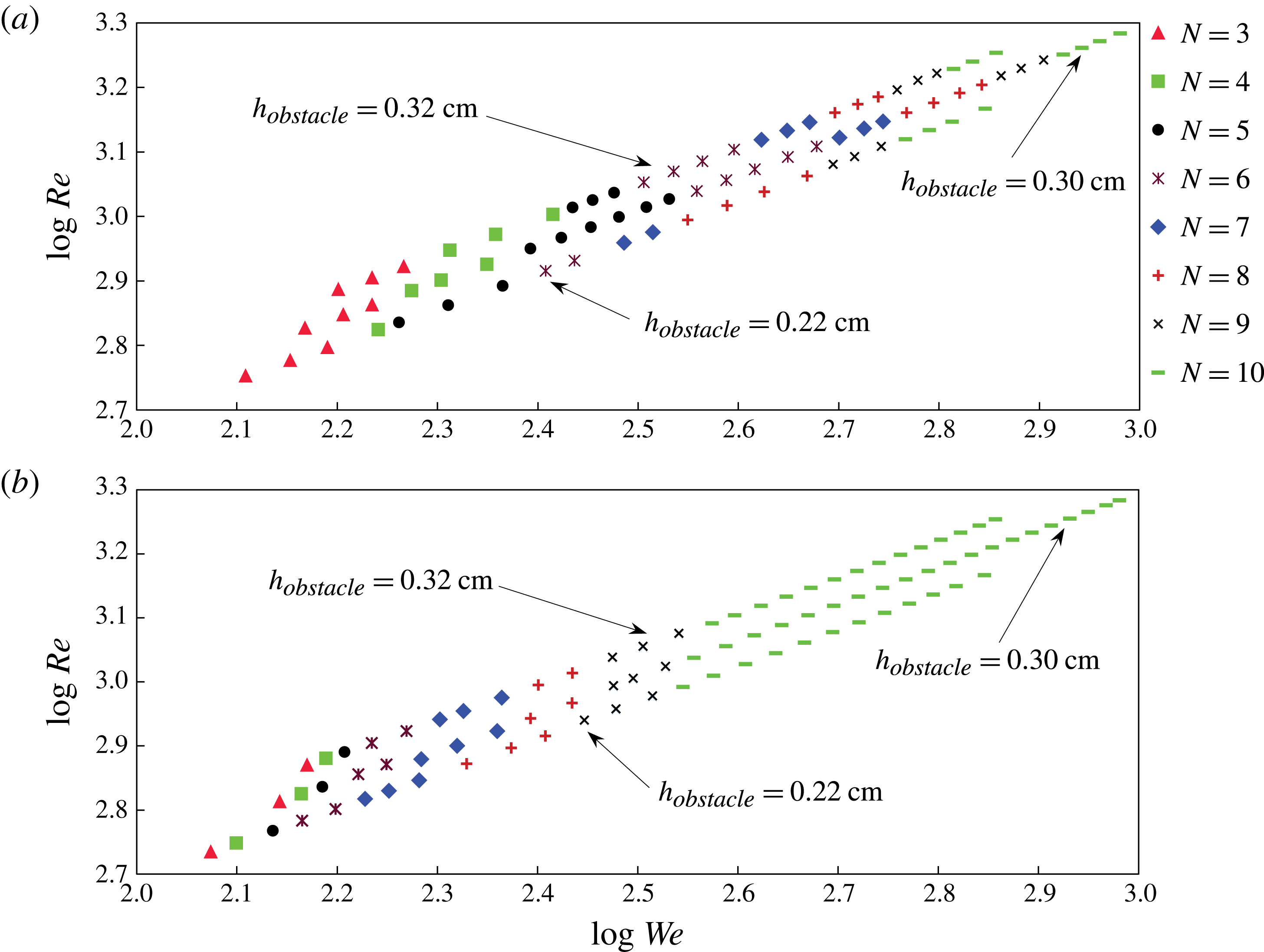
The dependence of stable polygonal hydraulic jump shapes on
 $\mathit{Re}=Q/({\it\nu}a)$
and
 $\mathit{We}={\it\rho}Q^{2}/({\it\sigma}H^{3})$
for
 $\mathit{Bo}=6.03$
according to our experimental data (
 $N$
determines the number of jump corners). (a) The flow rate is increasing. (b) The flow rate is reducing. The results were obtained using ethylene glycol released from a nozzle of radius
 $a=0.515\ \text{cm}$
at a height 1 cm above the impact plate.

Figure 6 shows the dependence of the shapes of stable jumps on
 $\mathit{Re}$
and
 $\mathit{We}$
for three different obstacle heights at
 $\mathit{Bo}=6.03$
. The Reynolds number is in the range of 500–2000, which shows that the flow is laminar. In this range of Reynolds number, different shapes of polygonal jumps from triangular to 10-sided were observed. The Weber number is in the range of 100–1000; it is notable that the Weber number depends on the value of
 $\mathit{Re}$
owing to the flow rate parameter. Each diagonal trace in figure 6 shows the influence of flow rate variations at a fixed obstacle height. In figure 6(a) the flow rate was increasing, and in figure 6(b) it was decreasing. Just as observed, these are clearly different. It should be mentioned that the results reported by Bush et al. (Reference Bush, Aristoff and Hosoi2006) did not illustrate this, whereas our experimental observations demonstrated that the transformation of a polygonal jump into another one with different corner number depends on whether the flow rate is increasing or decreasing. This refers to the multistability or hysteresis of polygonal jumps; in the other words, several polygons can be stable in a constant parameter regime.
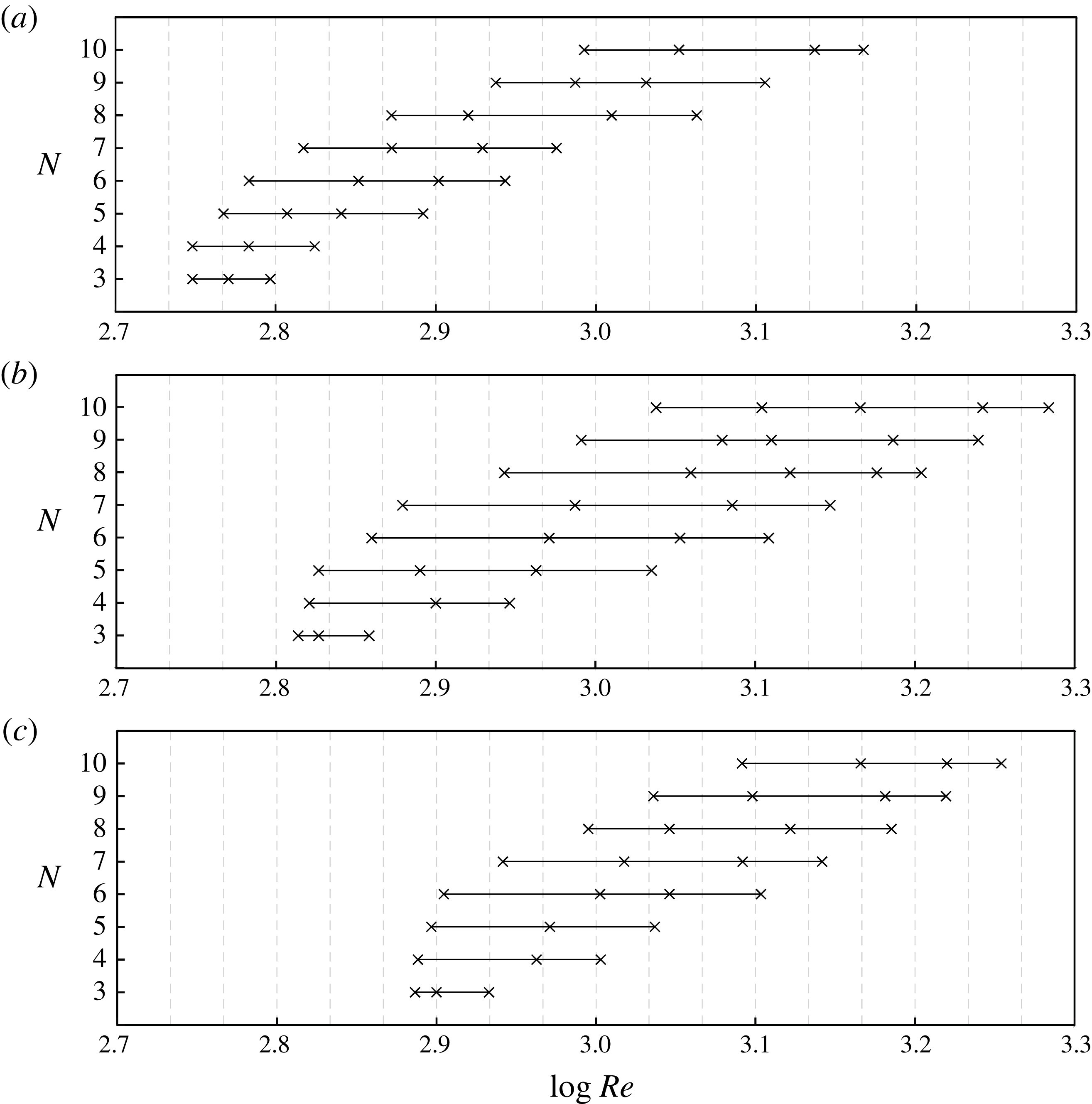
The experimental results show that when a polygonal jump is created with a specific number of corners, the number of corners remain unchanged even as the flow rate or downstream height are changed to a certain extent. We named this parameter regime over which a particular type of jump can be observed with hysteresis being taken into account as a ‘region of stability of a non-circular hydraulic jump’. In this region, the number of corners is constant; however, the size of the jump can be expanded by increasing, or contracted by decreasing, the flow rate at constant downstream height. The region of stability for each
 $N$
-sided jump is limited by a minimum and a maximum flow rate. When the flow rate is increased over the maximum flow rate, the polygon changes to a new one with an additional corner (
 $(N+1)$
-sided jump); likewise, if the flow rate is decreased under the minimal limit, two corners merge together and a polygonal jump will emerge with
 $N-1$
corners.
Demonstration of the experimental region of stability for stable polygonal jumps: (a)
 $h_{obstacle}=0.22\ \text{cm}$
, (b)
 $h_{obstacle}=0.30\ \text{cm}$
and (c)
 $h_{obstacle}=0.32\ \text{cm}$
. Here
 $\mathit{Re}=Q/({\it\nu}a)$
and
 $N$
is the number of jump corners. Each straight horizontal line displays the region of stability for a certain polygonal. The results were obtained using ethylene glycol released from a nozzle of radius
 $a=0.515$
cm at a height 1 cm above the impact plate.

Figure 7 illustrates the region of stability of stable polygonal jumps in terms of the jet Reynolds number for three different obstacle heights. The advantage of this diagram against the diagram reported by Ellegaard et al. (Reference Ellegaard, Hansen, Haaning, Hansen, Marcusson, Bohr, Hansen and Watanabe1999) and Bush et al. (Reference Bush, Aristoff and Hosoi2006) is that it indicates the possibility of the formation of several polygonal jumps with different corners at constant parameter. The multistability (hysteresis) of polygonal jumps with different corners was reported in Ellegaard et al. (Reference Ellegaard, Hansen, Haaning, Hansen, Marcusson, Bohr, Hansen and Watanabe1999). They mentioned that several polygons can be stable at the same parameters, but they did not report the details of the experimental results. Figure 7 indicates that the regions of stability of the jumps with different corners overlap; this is due to a hysteresis effect of the phenomenon. The experimental observations and measurements show that, for various obstacle heights, the stability zones are not equal, so that there is a unique downstream depth in which the length of the stability zone is maximum.
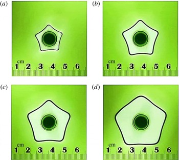
The effect of flow rate on a stable pentagonal hydraulic jump in its region of stability: (a)
 $Q=40.8\ \text{ml}\ \text{s}^{-1}$
, (b)
 $Q=46.8\ \text{ml}\ \text{s}^{-1}$
, (c)
 $Q=52.3\ \text{ml}\ \text{s}^{-1}$
and (d)
 $Q=61.4\ \text{ml}\ \text{s}^{-1}$
. Here
 $a=0.515$
cm and
 $H=0.6{-}0.62$
cm.

The effect of downstream height on a stable heptagonal jump at constant flow rate
 $Q=56.5\ \text{ml}\ \text{s}^{-1}$
subject to different downstream heights: (a)
 $H=0.59$
cm, (b)
 $H=0.68$
cm. Here
 $a=0.515$
cm.

As mentioned earlier, when the flow rate increases or decreases in the region of stability, the polygonal jump tends to maintain the number of its corners. But each polygonal hydraulic jump has a minimum and a maximum size in its stability zone. The influence of increasing the flow rate on a stable pentagonal jump in its region of stability is illustrated in figure 8. The investigations also revealed that the sides of polygons lose their concavity with increasing jet flow rate. The variations of downstream height, which provide appropriate pressure force, affect the number of corners, size, concavity of the sides and the structure (type) of the polygonal jumps. Two heptagonal jumps at constant flow rate subject to different downstream heights are shown in figure 9. As seen, by increasing the downstream height, the jump area is clearly reduced, the corners of the jump become sharper and the curvature of the sides is changed slightly. It is notable that, owing to figure 7, the rising downstream height can also lead to a reduction in the number of corners.
3.2. Unstable polygonal hydraulic jumps
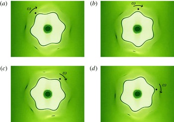
We observed a new type of non-circular hydraulic jump in this study with a rotational-wavelike behaviour (see supplementary movies 1 and 2 available at http://dx.doi.org/10.1017/jfm.2014.646). These types have not been reported in the literature at the time of writing. Owing to their rotational feature, we called them rotational hydraulic jumps. A rotational jump with six corners at four successive moments is shown in figure 10.
A rotational jump with six corners at four successive moments: (a)
 $0\ \text{s}$
; (b)
 $0.5\ \text{s}$
; (c)
 $1\ \text{s}$
; (d)
 $1.5\ \text{s}$
. Black dots are drawn at a specified corner. Here
 ${\it\omega}=12.33\ \text{r.p.m.}$
,
 $Q=70.6\ \text{ml}\ \text{s}^{-1}$
,
 $a=0.385$
cm and
 $H=0.70$
cm.

The rotational jumps arise at higher downstream height than for stable jumps. When the downstream height of a stable polygonal jump is increased, its sides lose their stability and become progressively unstable with a wavelike instability on their edges. Further increasing the downstream height causes the instability to encompass the whole jump and finally a time-dependent jump will appear with the specific number of sides which rotates with constant angular velocity. It seems that the downstream liquid height is an experimental control parameter that triggers the onset of rotational modes.
As shown in figure 10 and supplementary movies 1 and 2, it is clear that the shape of a rotational jump is symmetric. A tiny deviation of the impact plate from the horizontal level and the liquid jet from the vertical make the jump irregular and asymmetric. So great care was taken in levelling the target plate; consequently, the rotational modes are not due to an imbalance experiment.
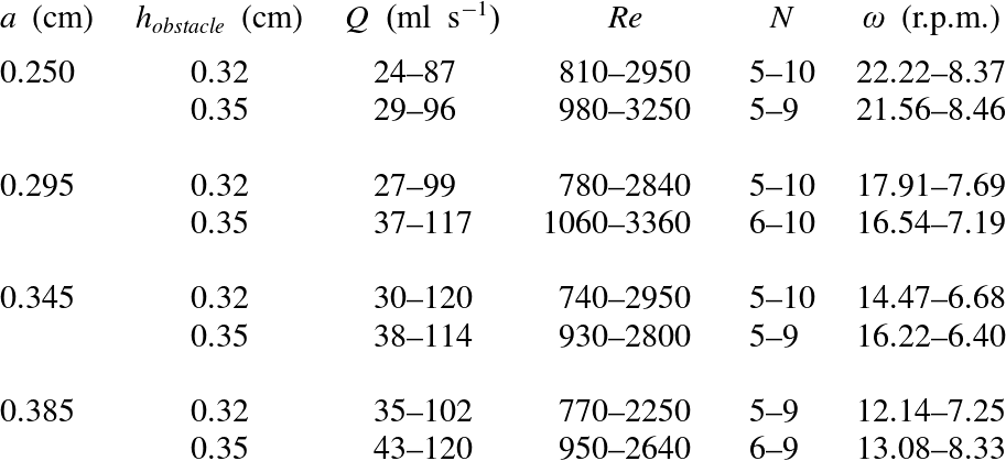
It should be mentioned that, in the present experimental set-up, the height of the downstream obstacle was adjusted by four Plexiglas rims with various thicknesses of 0.22, 0.3, 0.32 and 0.35 cm, separately. These rims have been located on the target plate as shown in figure 3. The height variation was not continuous; therefore, by this apparatus, the critical height for transition to the rotational modes cannot be reported. However, in this experimental research, the rotational modes for nozzles with radii of
 $a=0.250$
, 0.295, 0.345 and 0.385 cm and obstacle heights of
 $h_{obstacle}=0.32$
and 0.35 cm in some range of flow rate as reported in table 1 are observed.
Bush & Aristoff (Reference Bush and Aristoff2003) introduced different types of jump structures, which are illustrated in figure 11. As indicated, all types are marked by the separation of the boundary layer below the jump and on the target plate. In type II, there is a region of reversed flow after the hydraulic jump that is known as the surface roller (Liu & Lienhard Reference Liu and Lienhard1993).
A schematic sketch of three different types of circular hydraulic jump.

Some experimental conditions to achieve different rotational jumps.

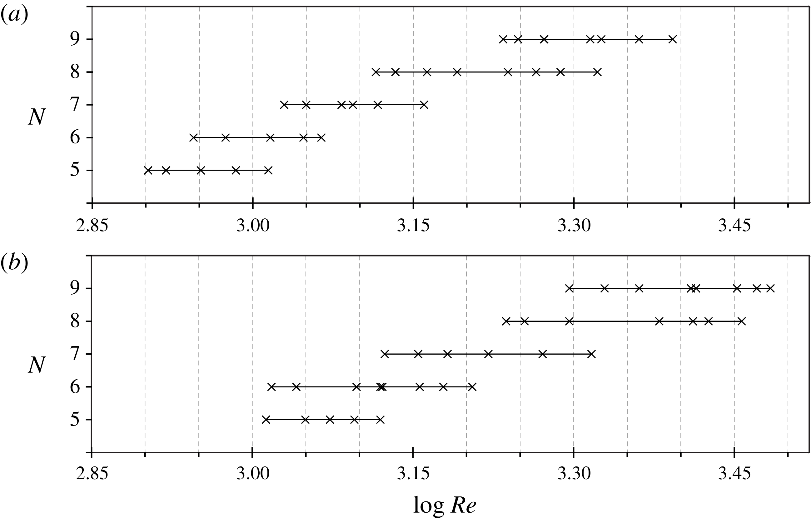
Demonstration of the experimental region of stability for rotational jumps: (a)
 $h_{obstacle}=0.32$
cm and (b)
 $h_{obstacle}=0.35$
cm. Here
 $\mathit{Re}=Q/({\it\nu}a)$
and
 $N$
is the number of jump corners. Each straight horizontal line displays the region of stability for a certain polygon. The results were obtained using ethylene glycol released from a nozzle of radius
 $a=0.345$
cm at a height 1 cm above the impact plate.

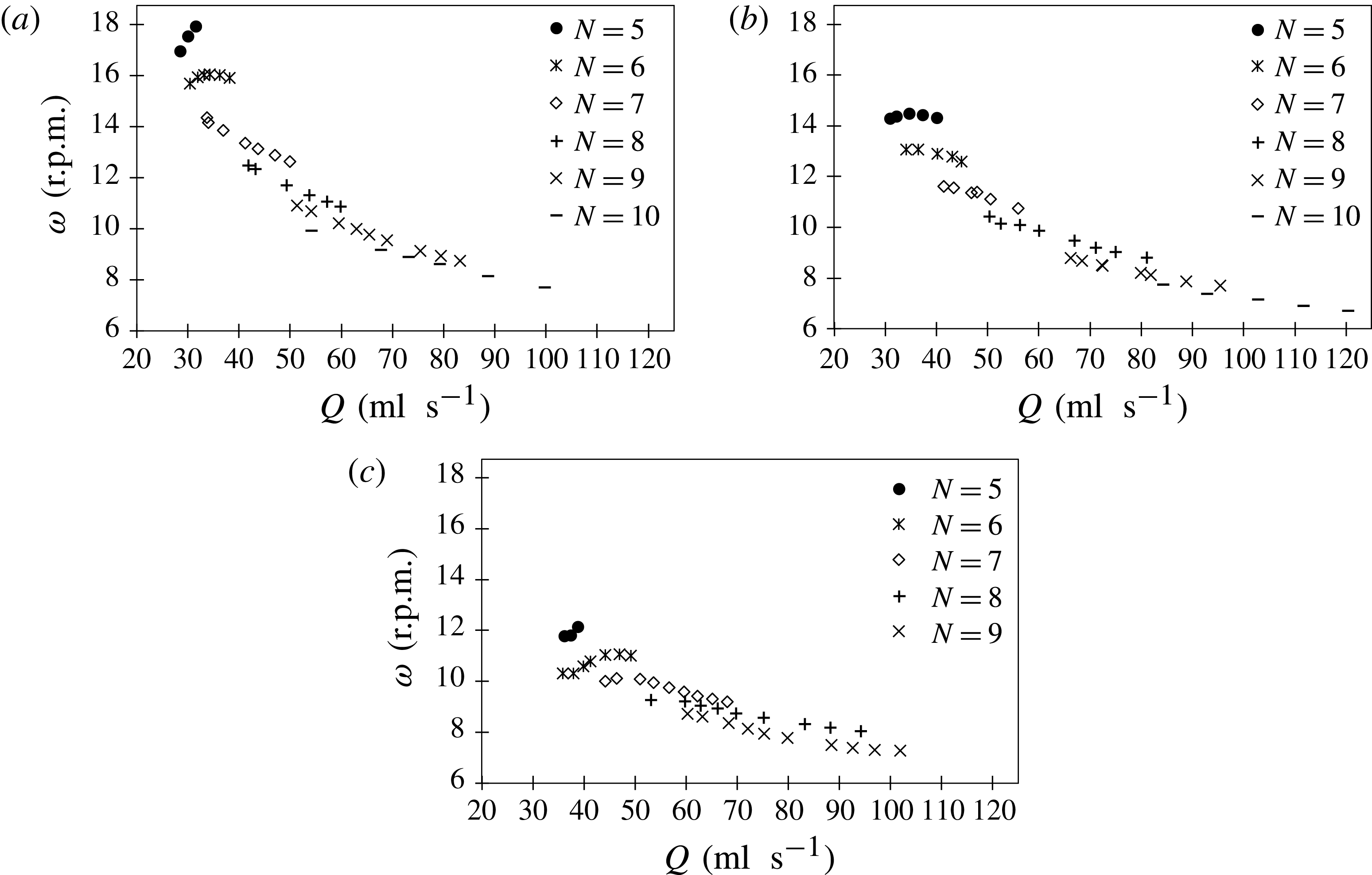
Variations of angular velocity of rotational hydraulic jumps versus flow rate at
 $h_{obstacle}=0.32$
cm for three different nozzle diameters: (a)
 $a=0.295$
cm, (b)
 $a=0.345$
cm and (c)
 $a=0.385$
cm. Here
 $N$
is the number of jump corners.

By injecting dye or air microbubbles into the liquid, it is evident that the nature of the ‘rotational jumps’ is some kind of surface wave along the jumps with their rotation randomly distributed in clockwise/anticlockwise directions. It is also clear that the structure of vortices can be revealed. Based on the experimental observations, it seems that there are some small eddies adjoining the corners of the jump, which exhibit a slight asymmetry as perhaps expected by a drift-induced motion. The locations of these eddies are close to the edges of the polygon towards the corners (see supplementary movie 3 available at http://dx.doi.org/10.1017/jfm.2014.646).
Similar to the stable polygonal jumps, there is a surface roller downstream of the rotational jumps. Although this structures was not clearly observed, it seems that these jumps have a structure very similar to type IIb jumps that has already been presented by Bush et al. (Reference Bush, Aristoff and Hosoi2006).
Just like the stable polygonal jumps, increasing or decreasing the flow rate causes the size of rotational jumps to become larger or smaller, without any variation in the number of corners. Therefore, it is possible to define the region of stability for these types of jumps as well. Figure 12 shows the region of stability for two different obstacle heights downstream.
An interesting feature regarding the rotational jumps is that, if the parameter regime (such as jet radius, flow rate, downstream height and the corner number) is fixed, the angular velocity will not vary. So, the angular velocity of the jump can be changed in the region of stability (figure 13). However, the rotation direction or the direction of wave motion may be clockwise or anticlockwise. Figure 13 also indicates the variations of angular velocity versus flow rate at
 $h_{obstacle}=0.32$
cm for three various nozzle radii.
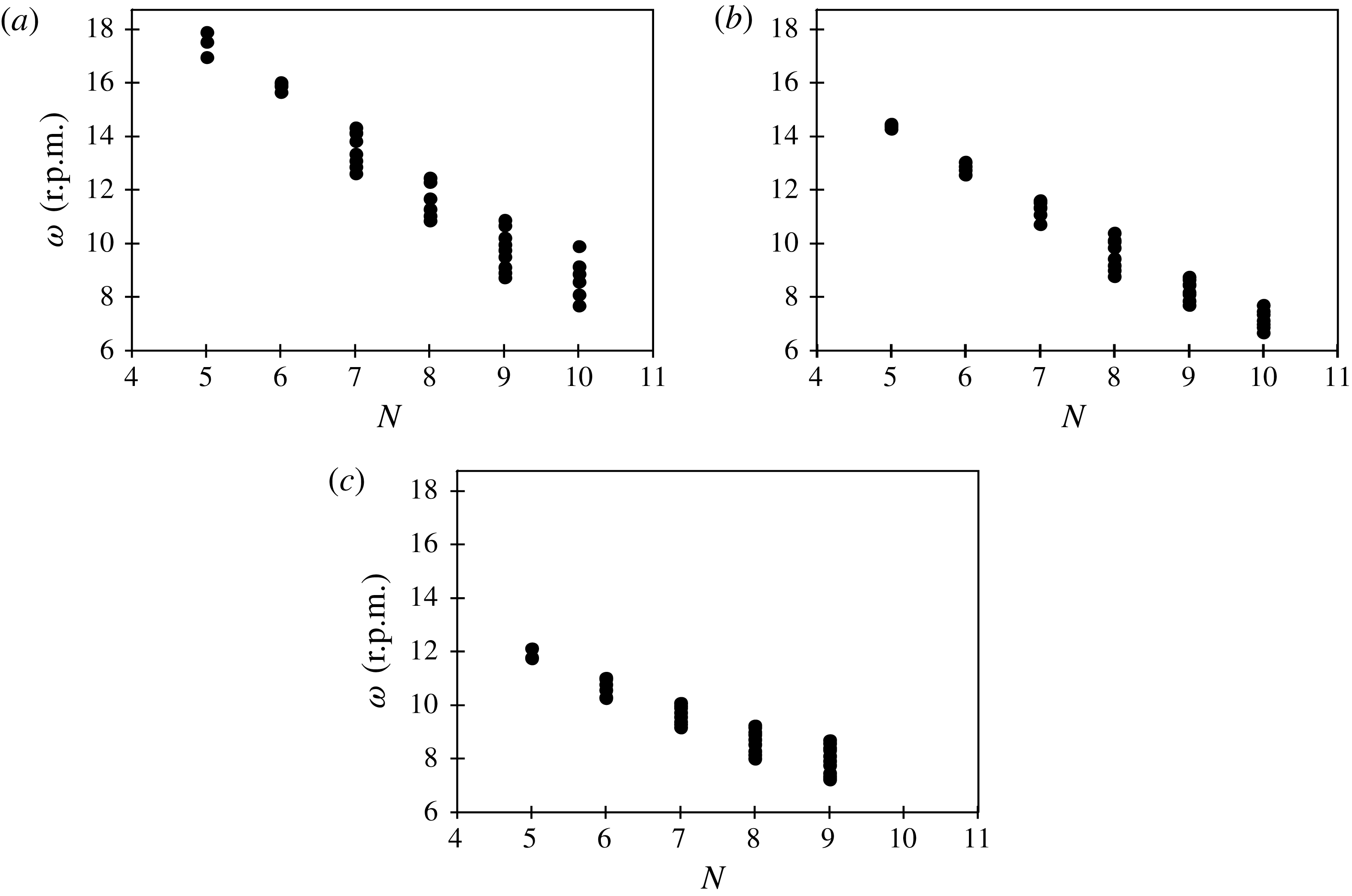
As shown in figure 13, the experiments reveal that the jet radius affects the angular velocity of the rotational jump. As indicated, by increasing the jet radius, the angular velocity reduces. The angular velocity in separate regions of stability versus corner number is plotted in figure 14; it seems that by increasing the corner number, the angular velocity decreases, and this relation looks inversely linear.
The variations of angular velocity in separate regions of stability versus the corner number at
 $h_{obstacle}=0.32$
cm for three different nozzle diameters: (a)
 $a=0.295$
cm, (b)
 $a=0.345$
cm and (c)
 $a=0.385$
cm.

3.3. Dimensions of non-circular jumps
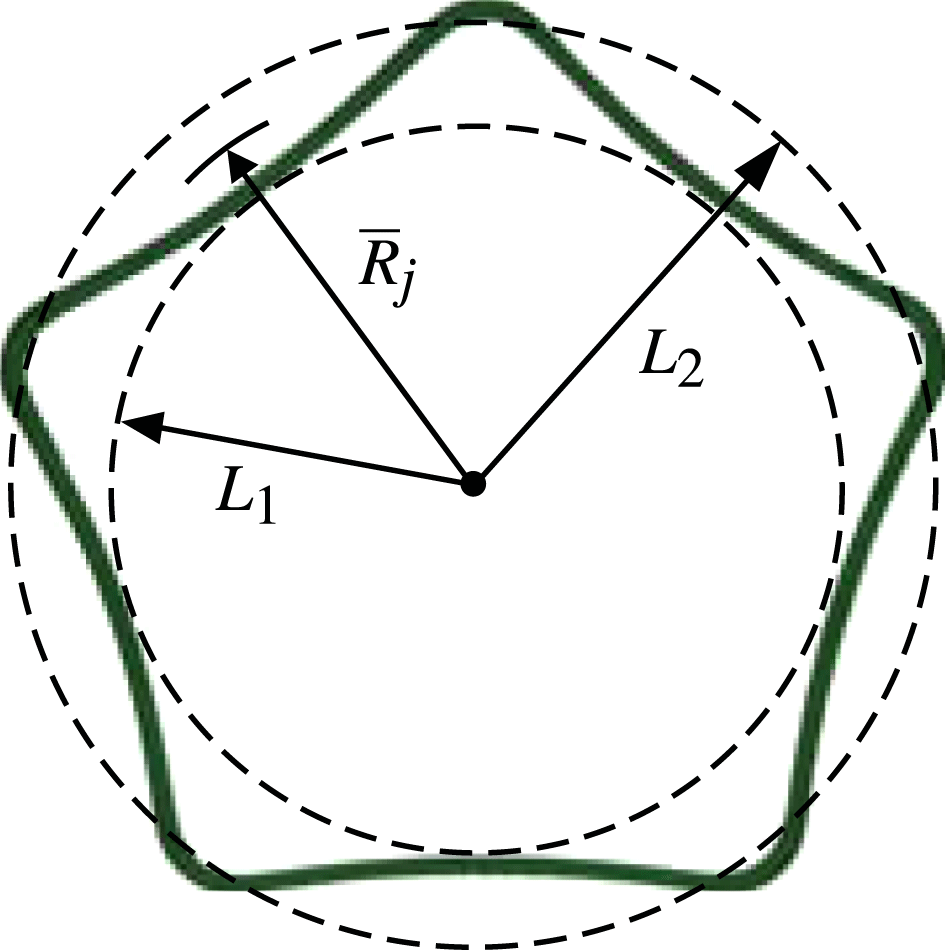
A schematic of the polygonal jump is shown in figure 15. There,
 $\mathit{L}_{1}$
and
 $\mathit{L}_{2}$
are inscribed and circumscribed circular radii of the polygon, respectively. These were measured by a ruler below the glass target plate. The digital images of this measurement were imported to a graphics editing program to get precise dimensions of the jump with an accuracy of 0.1 mm. By defining dimensionless ratios of
 $\mathit{L}_{1}/H$
and
 $\mathit{L}_{2}/H$
, where
 $H$
is the downstream height of the jump, the variations of
 $\mathit{L}_{1}/H$
and
 $\mathit{L}_{2}/H$
versus
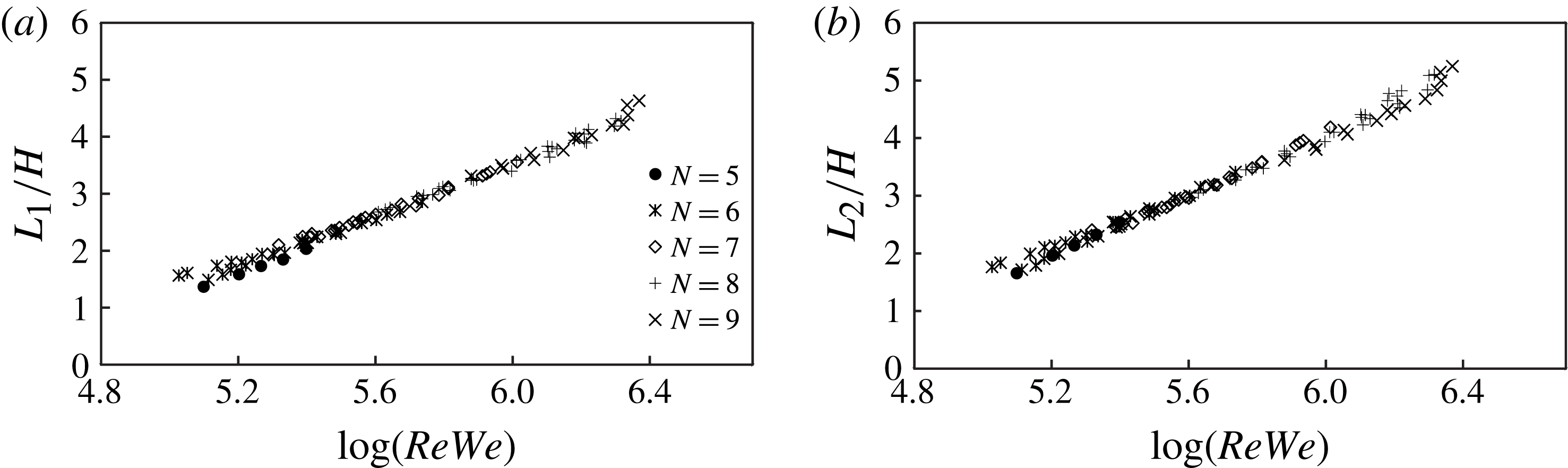
 $\log (\mathit{Re}\,\mathit{We})$
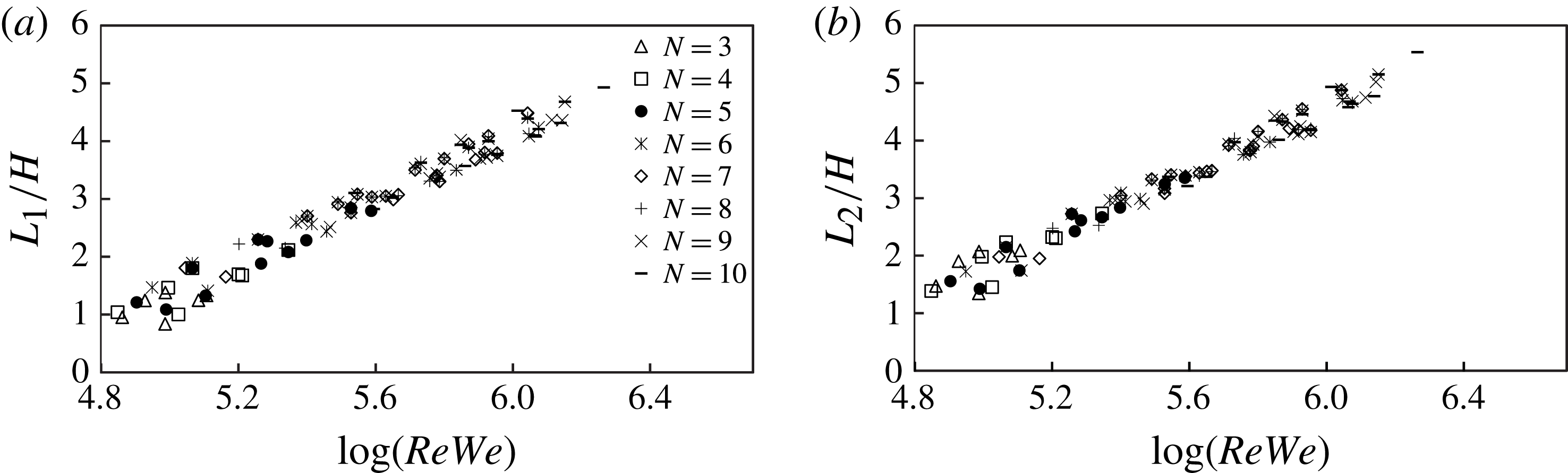
for stable polygonal and rotational jumps are illustrated in figures 16 and 17, respectively. As expected, by increasing
 $\mathit{Re}$
or
 $\mathit{We}$
caused by an increase of volumetric flow rate or a decrease of downstream height, a polygonal jump with larger inscribed and circumscribed circular radii will be formed. In addition, it seems that there is a linear relationship between
 $\mathit{L}_{1}/H$
,
 $\mathit{L}_{2}/H$
and
 $\log (\mathit{Re}\,\mathit{We})$
.
A schematic of the polygonal jump.

Variations of
 $L_{1}/H$
and
 $L_{2}/H$
versus
 $\log (\mathit{Re}\,\mathit{We})$
for stable polygonal jumps in which
 $L_{1}$
and
 $L_{2}$
are the inscribed and circumscribed circular radii of the polygon, respectively.

Variations of
 $L_{1}/H$
and
 $L_{2}/H$
versus
 $\log (\mathit{Re}\,\mathit{We})$
for rotational jumps in which
 $L_{1}$
and
 $L_{2}$
are the inscribed and circumscribed circular radii of the polygon, respectively.

Another interesting feature that we encountered is that
 $\mathit{L}_{1}$
and
 $\mathit{L}_{2}$
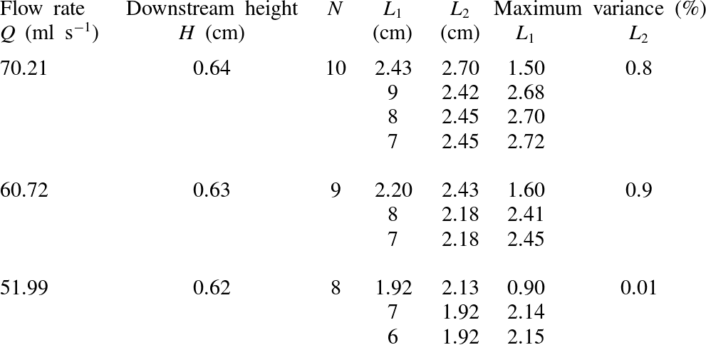
are always constant for several polygonal jumps at the same flux, the same downstream height and the same jet radius. As an example, table 2 presents separate results that were obtained for a fixed volumetric flow, downstream height and jet radius for many of the polygonal jumps. The maximum percentage of variance is less than 2 %, which seems to be due to measurement errors. Based on this feature, it is possible to define a mean radius
 $\bar{R_{j}}$
for each polygonal jump such as in Bush et al. (Reference Bush, Aristoff and Hosoi2006). Mean radius is useful to make a subjective comparison between experimental results and the theoretical prediction for the radius of the circular jumps and also to answer this question: Does the circular theory correspond to rotational jumps?
3.3.1. Watson’s theory
Watson’s viscous theory (Watson Reference Watson1964) is the most credible theoretical solution to determine the radius of circular jumps. Bush & Aristoff (Reference Bush and Aristoff2003) modified this theory by introducing the effect of surface tension. According to the modified Watson’s theory, there are two different equations to obtain the jump radius depending on the jump location. Briefly, jump radius (
 $R_{j}$
) is defined by
 $$\begin{eqnarray}\frac{R_{j}H^{2}ga^{2}}{Q^{2}}\left(1+\frac{2}{\mathit{Bo}_{j}}\right)+\frac{a^{2}}{2{\rm\pi}^{2}R_{j}H}=\left\{\begin{array}{@{}ll@{}}0.10132-0.1297\left(\displaystyle \frac{R_{j}}{a}\right)^{3/2}\!\mathit{Re}^{-1/2}, & R_{j}<r_{0},\\ 0.01676\left[\left(\displaystyle \frac{R_{j}}{a}\right)^{3}\!\mathit{Re}^{-1}+0.1826\right]^{-1}, & R_{j}>r_{0},\end{array}\right.\end{eqnarray}$$
where
 $r_{0}=0.315aRe^{1/3}$
is a certain radius and
 $\mathit{Bo}_{j}={\it\rho}gR_{j}{\rm\Delta}H/{\it\sigma}$
is the jump Bond number in which
 ${\rm\Delta}H$
is the height of the jump.
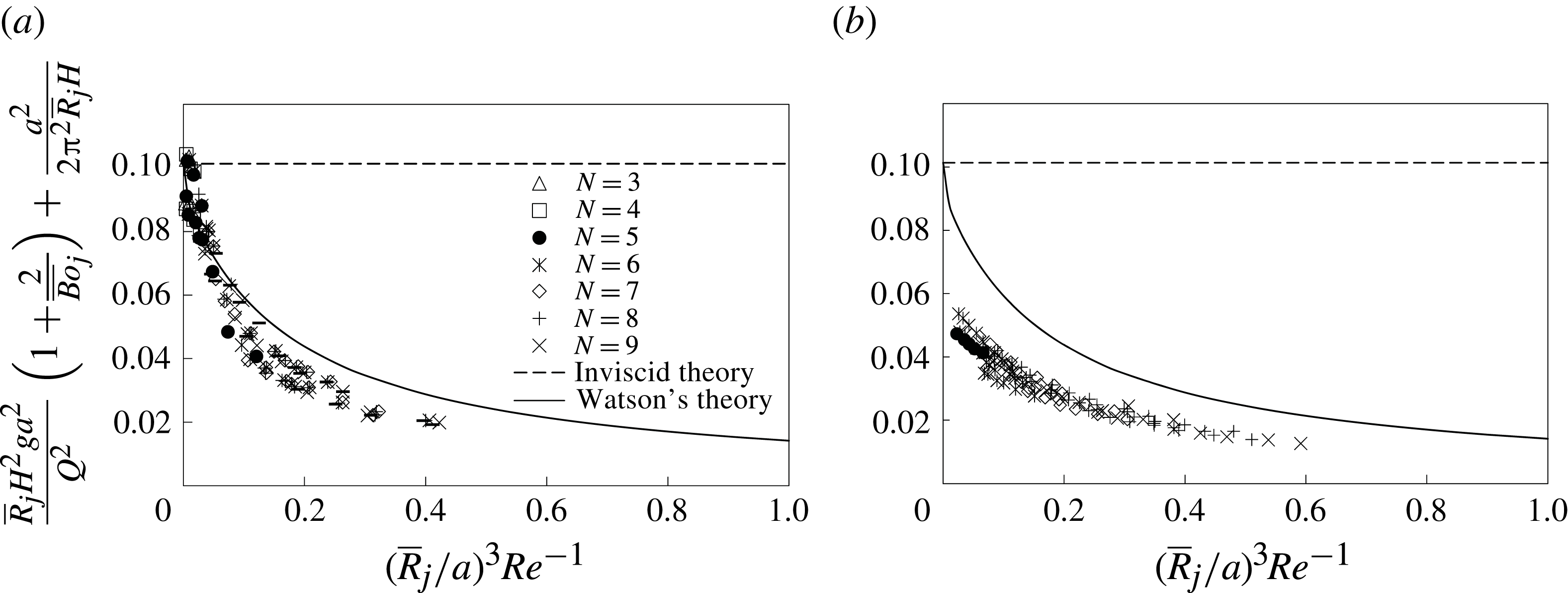
Comparison of the experimental result of the mean radius for (a) stable and (b) rotational polygonal jumps with the inviscid and Watson’s theories.

Results obtained for a fixed jet radius
 $a=0.295$
cm. At the same flux
 $Q$
and the same downstream height
 $H$
,
 $\mathit{L}_{1}$
and
 $\mathit{L}_{2}$
are independent of number of corners.

However, it seems that the application of Watson’s theory is ad hoc and it can only apply to circular jumps, but in order to compare the non-circular jumps with this theory, a mean jump radius was needed. In this study, the mean radius has been simply approximated by the average of
 $\mathit{L}_{1}$
and
 $\mathit{L}_{2}$
. Figure 18 indicates the comparison of the experimental result of the mean radius for stable and rotational polygonal jumps with Watson’s theory in a non-dimensional form. In plotting the mentioned figure, the same procedure as in Bush et al. (Reference Bush, Aristoff and Hosoi2006) has been taken in which the left-hand side of (3.1) is plotted in terms of a non-dimensional term as given in the figure. As figure 18(a) indicates, there is a rather good trend between mean jump radius and Watson’s theory for stable polygonal jumps. However, figure 18(b) shows that the mean radii of rotational jumps based on experimental results have a good trend, but does not coincide with Watson’s theory as well as the former.
The deviations between experimental data and Watson’s theory may come from the fact that the structure of a rotational jump is quite different from a type I circular jump (Watson’s theory) but as mentioned before a rotational jump is very similar to type IIb. In addition, the instability and time dependence of rotational jumps are additional factors that are not considered in Watson’s theory.
4. Conclusion
It was observed that a fast instability on circular hydraulic jumps is the cause of the formation of polygonal ones; this phenomenon has a reason like Rayleigh–Plateau instability, introduced by Bush et al. (Reference Bush, Aristoff and Hosoi2006) and analysed by Martens et al. (Reference Martens, Watanabe and Bohr2012). It was also mentioned that there is a certain parameter regime that makes a circular jump unstable and leads to a polygonal jump. The purpose of the current study was to present the experimental results of non-circular hydraulic jumps. We divided the non-circular jumps into two main kinds: stable and unstable (rotational) jumps. First, we defined a special region as the region of stability of a non-circular hydraulic jump; then the dependence of this region on the jet Reynolds number was determined. These results indicated the role of hysteresis in the formation of several polygonal jumps with different corners in a constant parameter regime. In addition, the results illustrated that in the region of stability for each polygonal jump, by increasing the flow rate, the jump area will increase and polygons lose their concavity. By increasing the downstream height, the jump area will decrease and the curvature of the sides will increase. A new kind of non-circular jump that has rotational behaviour with a constant angular velocity was also reported. Until the flow rate or downstream height is fixed, the angular velocity of a rotational jump does not change. Our observations indicated that the nature of a rotational jump is some kind of surface waves along the jump in clockwise or anticlockwise direction. It seems that these jumps have a structure very similar to a type IIb jump.
Afterwards, by investigating the polygonal jump sizes, it was determined that, at the same flux, the same downstream height and the same jet radius, the inscribed and circumscribed circular radii of several polygon jumps are independent of the number of corners. Therefore, a comparison between experimental results and Watson’s theory was made based on a mean radius for each polygonal jump.
Acknowledgement
The authors wish to express appreciation to the Vice-President for Research and Technology of Ferdowsi University of Mashhad for supporting this project through grant no. 2/28528.
Supplementary movies
Supplementary movies are available at http://dx.doi.org/10.1017/jfm.2014.646.