1. Introduction
A resorbable material is one which dissolves in a specified environment in the way that rock salt or polyvinyl acid (PVA) dissolves in water, polylactic acid (PLA) dissolves in vivo [Reference Sheikh, Najeeb, Khurshid, Verma, Rashid and Glogauer1], or ice melts into warm water. Resorbable materials have a wide range of material properties and resorption mechanics [Reference Ciccone, Motz, Bentley and Tasto2], which makes them desirable for a range of situations and applications. They have been investigated for use in biomedical applications, and their success in this area has led to advances in medicine which have greatly helped patients [Reference Sheikh, Najeeb, Khurshid, Verma, Rashid and Glogauer1, Reference Tschegg, Lindtner, Doblhoff-Dier, Stanzl-Tschegg, Holzlechner, Castellani, Imwinkelried and Weinberg3–Reference van Dijk, Smit, Sugihara, Burger and Wuisman8]. In current practice, the function of resorbable materials in biomedical applications is to dissolve away, such that the entire device – whether it be a pill, sutures, a stent, or even an electronic device [Reference Morsada, Hossain, Islam, Mobin and Saha9] – dissolves into the body. In these cases, the complete dissolvability of the device is a benefit because it removes the need for additional medical intervention after the device’s initial installation [Reference Huang10, Reference Pontell, Niklinska, Braun, Jaeger, Kelly and Golinko11].
While this complete dissolution is the primary application for resorbable materials [Reference Prasad, Chakraborty and Kumar12, Reference Yang, Chou, Ju and Lin13], they show promise for use as components of permanent mechanisms. Many have demonstrated the benefit of a resorbable materials incorporated into a permanent bone graft [Reference Regidor, Ortiz-Vigón, Romandini, Dionigi, Derks and Sanz14–Reference Giorgio, Andreaus, Scerrato and Dell’Isola16]. These resorbable materials did not actuate the bone graft – the bone graft did not move during its tenure in the body – but were a dissolving part of a larger permanent mechanism. Grosjean et al. designed self-actuating fully resorbable polymer tubes [Reference Grosjean, Ouedraogo, Déjean, Garric, Luchnikov, Ponche, Mathieu, Anselme and Nottelet17]. This device was not part of a larger, nonresorbable, permanent mechanism and was fully resorbable but did actuate itself. Despain et al. designed a nitinol stent that utilizes the polymer PDLG (a DL-lactide/Glycolide copolymer) to actuate gradually after insertion into an occluded artery [Reference Despain18]. The gradual stent deployment helps reduce high-impact stresses introduced to the artery characteristic of the current surgery, which introduces the stent already at its full diameter immediately into the artery. This is a more representative example of what this work describes and where the dissolution of a resorbable material allowed for physical actuation of a permanent mechanism.
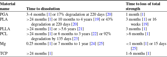
When used in tandem with a non-dissolving apparatus, resorbable materials provide a method for actuating mechanisms that exhibit unique benefits. These benefits are not available with the current practice of utilizing resorbable materials in applications where they dissolve entirely, as the benefits stem directly from utilizing resorbable materials as an actuation method for a permanent, nonelectronic mechanism. As demonstrated in [Reference Despain18], one of these benefits is that of an automatic and gradual deployment, followed by a period of time where the permanent mechanism remains in vivo continuing to perform its duty. Others include time-delayed response and tailorability: resorbable materials may take between minutes and months to fully dissolve (as shown in Table I) depending on the material itself, its environment, as well as the surface area, density, and shape of the resorbable component. For example, in cases where a shorter dissolution time is desirable, a material such as Mg or PGA – materials which dissolve comparatively quickly – might be chosen. In vitro, the temperature or stirring of the solvent might also be increased to shorten the dissolution time. Both in vivo and in vitro, the external surface area of the resorbable material might be increased (e.g., through perforation) or the density decreased (e.g., through a lower infill or different chemical structure) to further shorten the dissolution time. Each of these variables may be altered to achieve more control over dissolution time of a resorbable material, but the first applications most suited for this type of activation are those that do not require precise times of the actuation.
Various relevant bioresorbable materials and their dissolution times in vivo. Note that the listed dissolution times vary widely based on the molecular weight, crystalline degree, material shape, and implantation site [Reference Vieira, Vieira, Ferra, aes, Guedes and Marques19]. Note also that most resorbable implants are made of a composite of two or more of these or other materials, making their behavior even more difficult to predict.

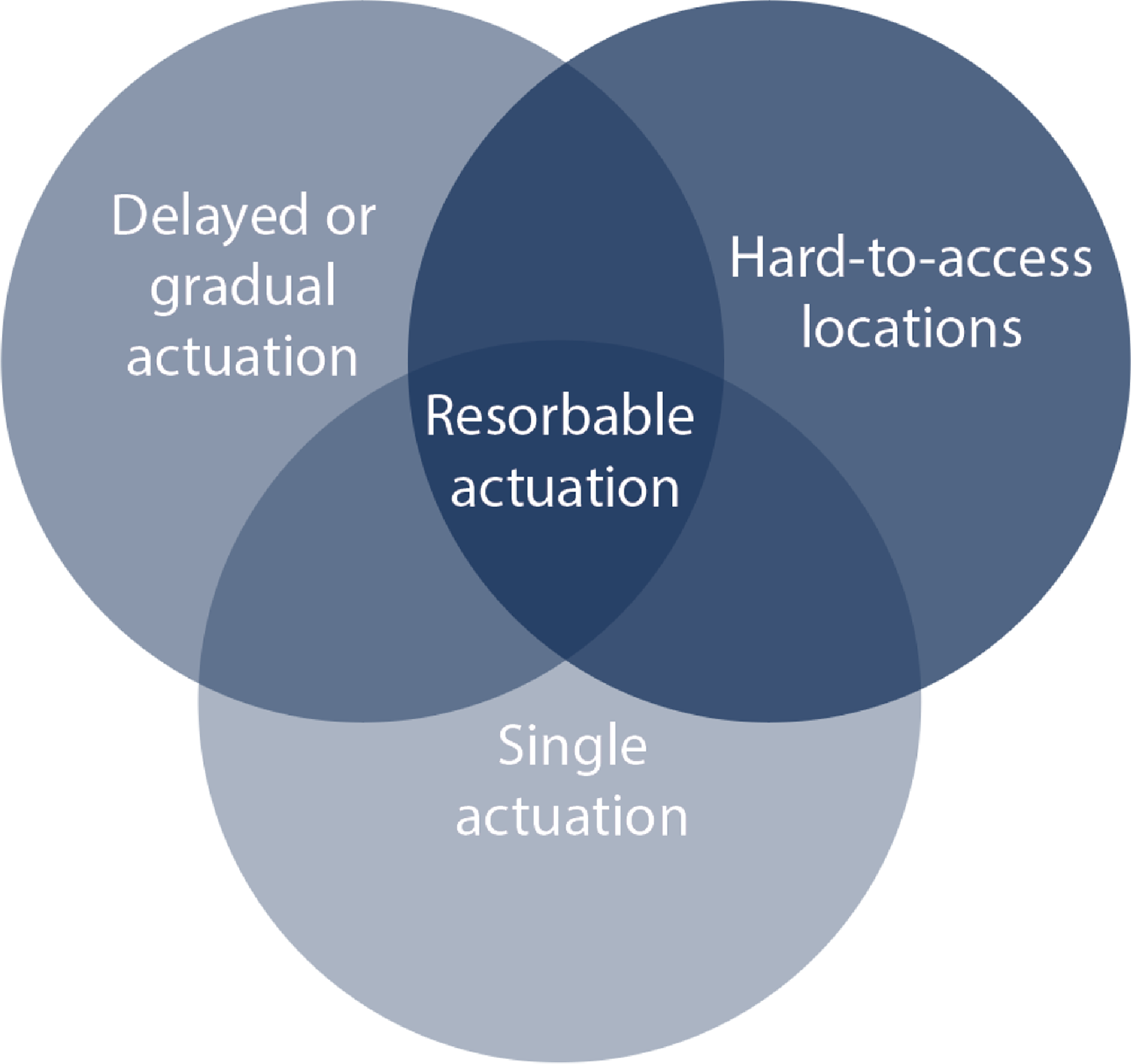
The benefits and feasibility of utilizing resorbable materials to trigger actuation are explored in greater detail throughout this work. A summary of the benefits of resorbable actuation is shown in Fig. 1.
A diagram displaying the intersection of situations in which resorbable actuation presents the greatest benefit.

This work explores the effects of desired mechanism actuation motion and speed, as well as resorbable material stress situation, to present a framework for investigating combinations of parameter values that may be used to implement resorbable material actuation in a mechanism. Using resorbable materials to actuate a non-dissolving apparatus, rather than as a temporary, dissolving device, is a promising and novel method for mechanism actuation.
2. Mechanism types
Identifying which mechanisms might benefit from the proposed resorbable-materials-based actuation method is aided by evaluating their method of obtaining actuation energy.
Some devices either remain static throughout their lifetime (e.g., the Nuss bar for pectus excavatum surgery [Reference Nuss, Obermeyer and Kelly26]) or move with a larger mechanism (e.g., a hip [Reference Čolić, Sedmak, Legweel, Milošević, Mitrović, Mišković and Hloch27] or knee [Reference Schütz, Postolka, Gerber, Ferguson, Taylor and List28, Reference Mehin, Burnett and Brasher29] implant, a durable (non-bioresorbable) coronary stent [Reference Morlacchi, Pennati, Petrini, Dubini and Migliavacca30], or an intraocular lens [Reference Findl, Kiss, Petternel, Menapace, Georgopoulos, Rainer and Drexler31, Reference Lesiewska-Junk and Kałużny32]).
Other devices require an external stimulus and external energy for activation. They are thus activated from outside the device (e.g., orthodontic braces [Reference Cattaneo, Dalstra and Melsen33], a palate expander [Reference Handelman, Wang, BeGole and Haas34], or a cochlear implant [Reference Lenarz35] (where the exterior speech processor can be removed, thus deactivating the system)). Still others require an external stimulus but use stored internal energy to power the activation. These devices often allow for remote activation without requiring direct physical interaction (e.g., magnetically controlled growing rods for scoliosis [Reference Teoh, Winson, James, Jones, Howes, Davies and Ahuja36, Reference Rushton, Smith, Kandemir, Forbes, Fender, Bowey, Gibson and Joyce37], programmable palate expanders [Reference Torres, AlYazeedy and Yen38], or remote-controlled implantable insulin pumps [Reference Schaepelynck, Darmon, Molines, Jannot-Lamotte, Treglia and Raccah39, Reference Renard40]).
Finally, other mechanisms use stored internal energy to power the activation and are thus auto-activated (e.g., an implantable cardioverter-defibrillator [Reference Mirowski41], a pacemaker [Reference DiFrancesco42, Reference Ouyang, Liu, Li, Shi, Zou, Xie, Ma, Li, Li and Zheng43], or multistage stent devices [Reference Skousen and Bowden44]). Bioresorbable scaffolds for cardiac stents [Reference Ang, Bulluck, Wong, Venkatraman, Huang and Foin45, Reference Iqbal, Onuma, Ormiston, Abizaid, Waksman and Serruys46] and controlled-release drug or macromolecule delivery systems [Reference Gao, Xu, Land, Harris, Policastro, Childers, Ritzman, Bundy and Becker47, Reference Holland, Tighe and Gould48] are a secondary case of auto-activated medical devices, where the device dissolves (rather than deploying) with time after implantation.
Resorbable materials may be used to actuate devices which utilize stored internal energy to power their activation; by placing the resorbable material in a permanent mechanism so that the mechanism is elastically deformed, the mechanism gains internal energy that is released as the resorbable material dissolves and allows the mechanism to return to its unstressed state. Resorbable materials are additionally primarily conducive for use in mechanisms which would benefit from a zero-stimulus activation – although with various adaptations from the methods presented here, they are also viable for mechanisms that use an internal or external stimulus to trigger activation. Use of resorbable materials is thus primarily beneficial for the final type of mechanism described: one which requires no stimulus and uses stored internal energy to power its activation. Resorbable material mechanism actuation, proposed here, is one of few existing cases of this final type of device.
Additionally, if the device’s location makes it difficult to actuate remotely or means that it cannot be activated externally, as is the case for many in vivo implants, the auto-activation of resorbable materials becomes particularly attractive. The use of resorbable materials thus provides solutions to previously difficult applications of mechanisms and proves promising for devices that must be embedded or implanted out of reach of further manipulation. For example, utilizing bioresorbable materials to actuate medical devices (e.g., self-adapting corrective implants) may produce minimally invasive, gradual, and less painful in vivo corrective procedures. Thus if a mechanism is in a hard-to-access location, requires delayed or gradual actuation, and needs a single actuation, resorbable materials are of particular interest, as shown in Fig. 1.
3. Development and testing
We demonstrate the functionality of resorbable materials as a means of actuation through four diverse test mechanisms. In these four mechanisms, we show that resorbable materials may be used under various stress situations (compression and shear loads), produce different final actuation motions (linear and rotational), and have different actuation speeds (gradual and delayed instantaneous), as listed in Table II. Each mechanism was designed and chosen for being a simple device which displayed a different combination of the above characteristics. The four mechanisms and the testing procedure used for each are described below. The objective of each test was to demonstrate the feasibility of the resorbable material as an actuation mechanism for each set of unique loading conditions.
The four tested mechanisms and their characteristics. These were selected to demonstrate the usability of resorbable materials as actuators for a diversity of stress situations, actuation motions, and actuation speeds.

Additional information on experimental design, including engineering drawings for each of the mechanisms and their corresponding resorbable inserts, as well as videos displaying the actuation for Mechanisms 2 and 4, is available in the Supplementary Material.
Mechanism 1: Simple twist
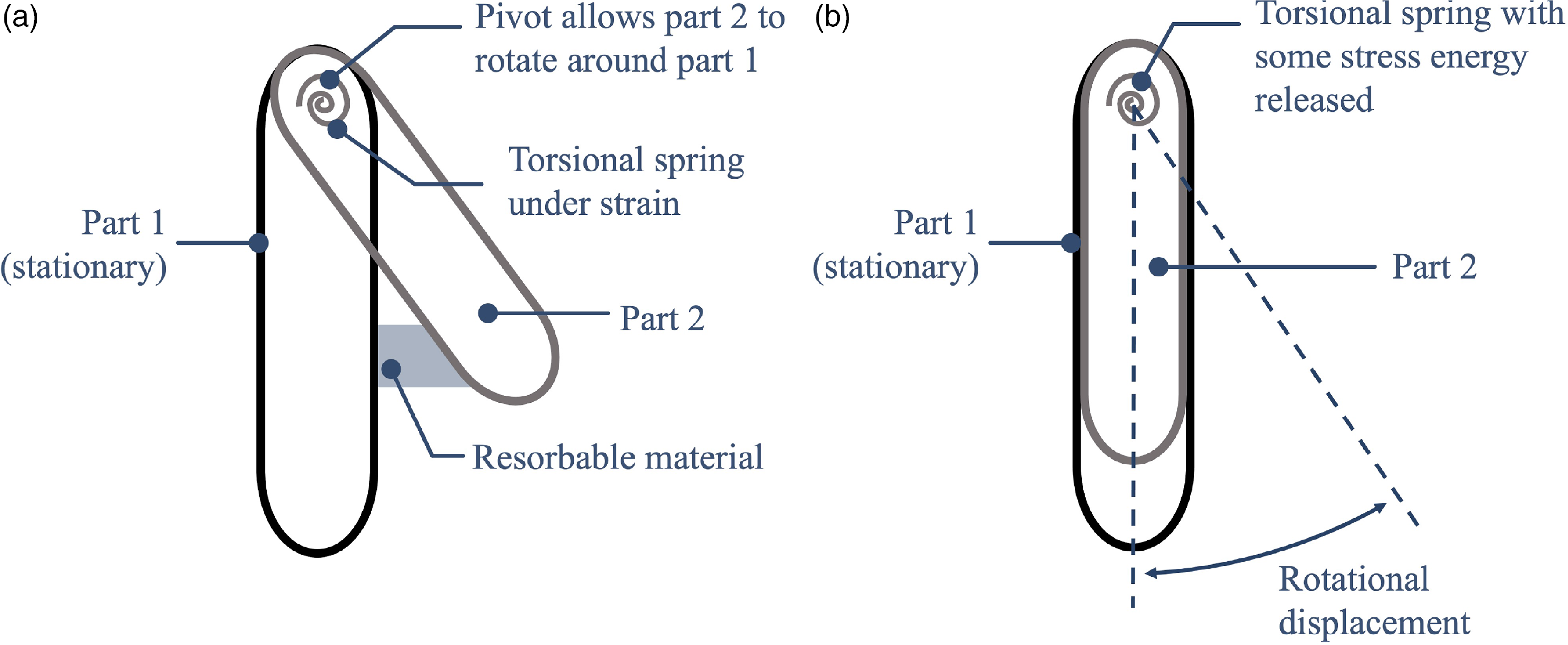
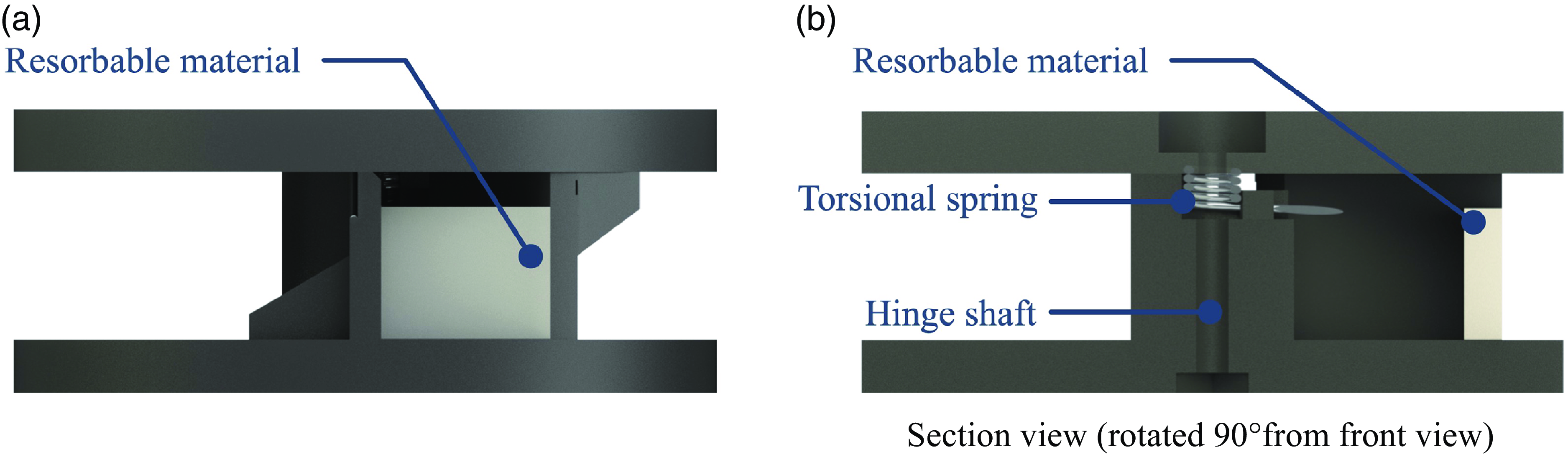
The rotation device illustrated in Fig. 2a is held in place with a torsional spring hidden in the central shaft. The mechanism is rotated, displacing the spring, and a resorbable insert is placed in compression such that the mechanism is held in its deformed position, as shown in Fig. 2b. The mechanism’s deformed position is shown in Fig. 2b. As the resorbable insert dissolves, the torsional spring pushes the mechanism toward its initial position (Fig. 2b). It is thus a gradually actuated mechanism.
Schematic of the basic concept of Mechanism 1. Part 2 rotates relative to part 1 as the resorbable material dissolves. (a) The two parts are connected at a pivot (hinge) with a torsional spring that stores potential energy which is (b) gradually released as the resorbable material dissolves.

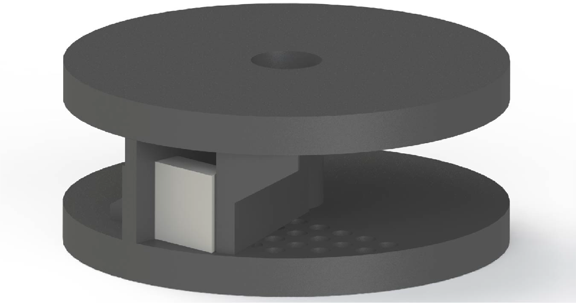
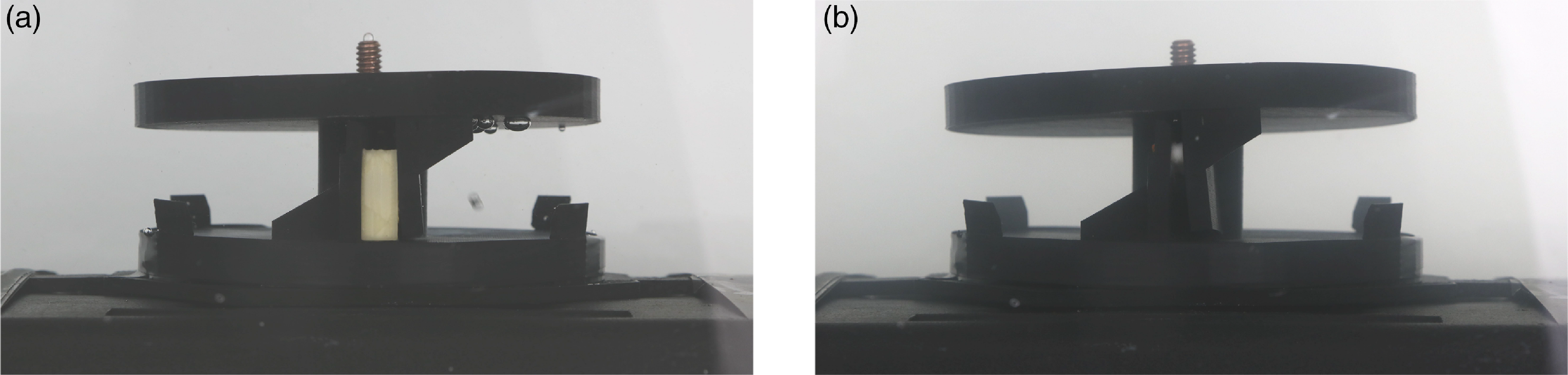
The physical prototype (shown in Fig. 3 and Fig. 4) was 3D printed out of PLA and tested with both PVA and rock salt as the resorbable material, both of which dissolve in water. Testing of Mechanism 1 was performed as follows: a tank was filled with 5 gallons of 43
 $^{\circ }$
C water. The resorbable inserts were placed in their designated locations in the mechanism. The mechanism and inserts were taped to a weight and set in the tank of water. Pictures of the mechanism’s actuation were taken once every 6 minutes.
Rendering of an isometric view of the simple twist mechanism.

Renderings of the twist design in a (a) front view and (b) section view (rotated 90
 $^{\circ }$
from front view). The white piece of resorbable material is visible, as well as the torsional spring which provides the actuation energy.

Twist test (a) before and (b) after the test which utilized PVA as the resorbable material. The insert is the off-white section visible in the center of the mechanism in (a).

Testing of the twist mechanism was performed first with PVA and then with rock salt as the resorbable insert. The PVA took over 12 hours to dissolve because of its sheltered location within the mechanism; the less water flow across the insert, the slower it dissolves. The rock salt, however, took approximately an hour. These relatively short times were used for the experiment but much longer times would likely be used in most applications.
Comparison between Fig. 5a and b demonstrates that the mechanism has rotated, closing a gap of approximately 20
 $^{\circ }$
. After 12 hours of dissolution when the PVA insert dissolved, the released torsional energy forced the mechanism to close that gap, bringing the two vertical black posts adjacent to one another. This test successfully demonstrated that resorbable materials may be used to actuate mechanisms which require rotational motion. The twist mechanism or similar might be used in an application where a valve needs to be gradually opened or closed over a period of time.
Mechanism 2: Folded-beam suspension
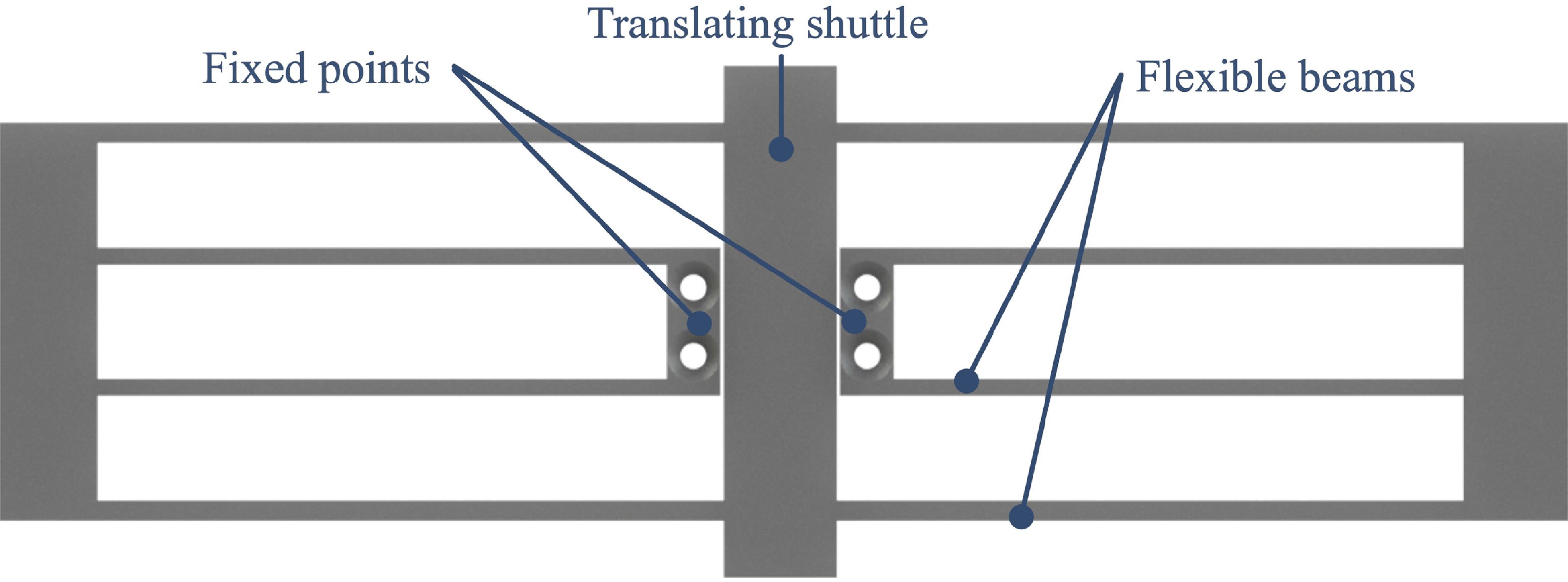
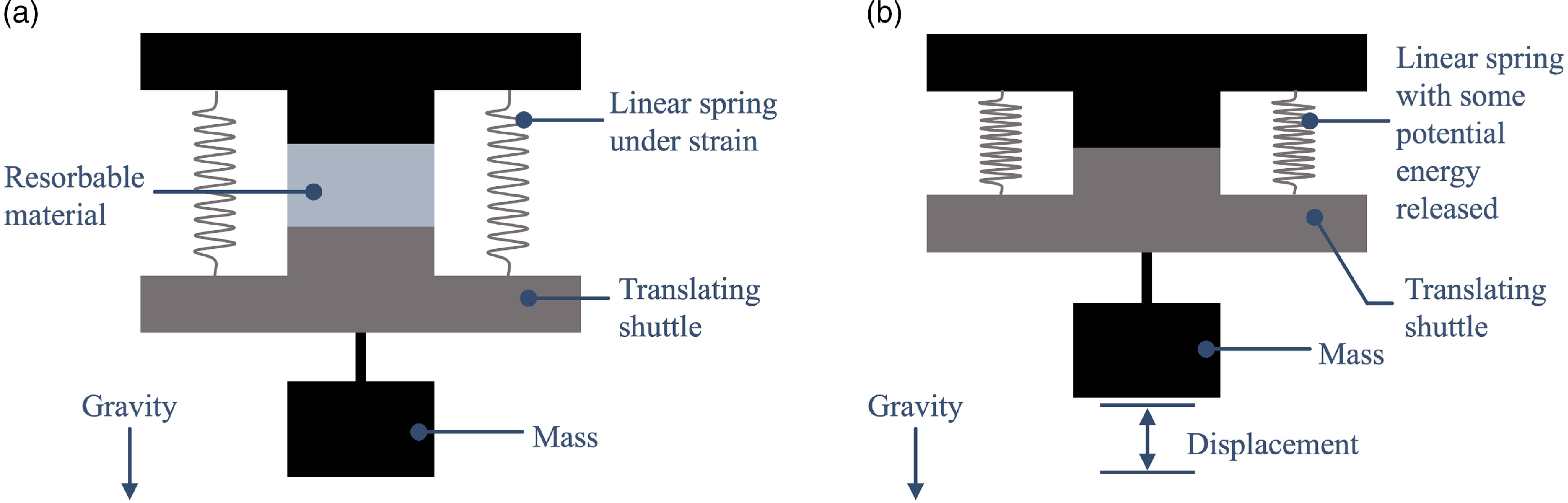
A folded-beam suspension allows the central translating shuttle to be displaced through its attachments to compliant members [Reference Derderian, Howell, Murphy, Lyon and Pack49, Reference Howell50] (as shown in Fig. 6). As the central beam is displaced, the compliant members gain strain energy, which forces the central translating shuttle back to its initial position. In the absence of something prohibiting the central shuttle’s motion back to the initial position, it will return immediately to its initial position. Placing a resorbable insert in compression between the central translating shuttle’s displaced and final positions (Fig. 7a) allows the shuttle to gradually return to its initial position (Fig. 7b). If the resorbable insert is thinned such that it will fail catastrophically, the beam can alternatively be made to return instantaneously to its initial position.
Rendering of the folded-beam suspension.

Schematic illustrating the basic concept of Mechanism 2. (a) The linear springs have stored potential energy. (b) The potential energy is released as the resorbable material dissolves and lifts the weight.

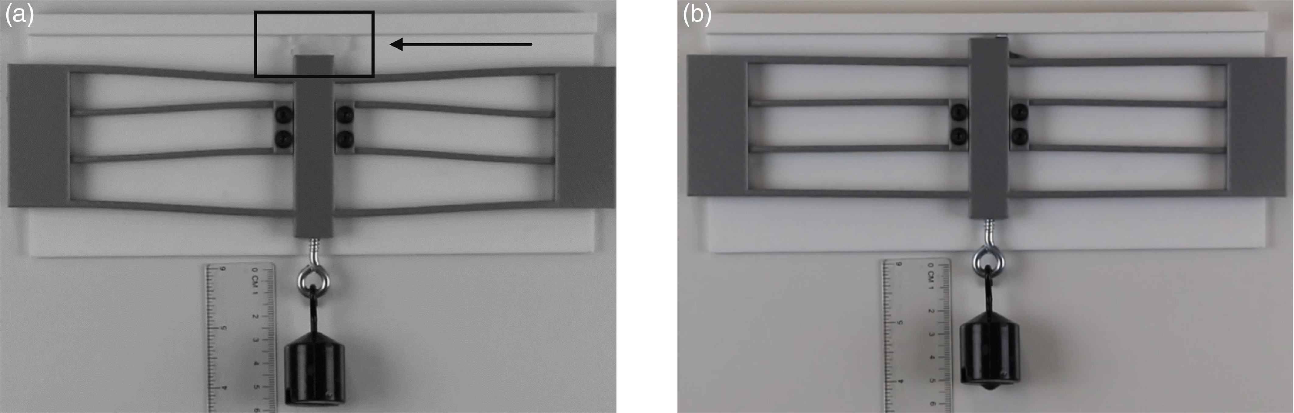
Linear test (a) before and (b) after, utilizing ice as the resorbable material. The ice is indicated by an arrow and box in (a).

This mechanism was 3D printed out of PLA and tested with both rock salt in 43
 $^{\circ }$
C water and ice in 21
 $^{\circ }$
C air. Testing of Mechanism 2 was performed as follows: the mechanism was fixed to a vertical surface. A known weight (0.1 kg) was attached to the bottom of the central beam of the mechanism. The central beam of the folded-beam suspension was forcibly displaced. The resorbable insert was then placed in its designated location in the mechanism. Video was taken of the mechanism as the ice dissolved to record the actuation time, force, and displacement. A ruler was placed behind the mechanism to measure its displacement over time.
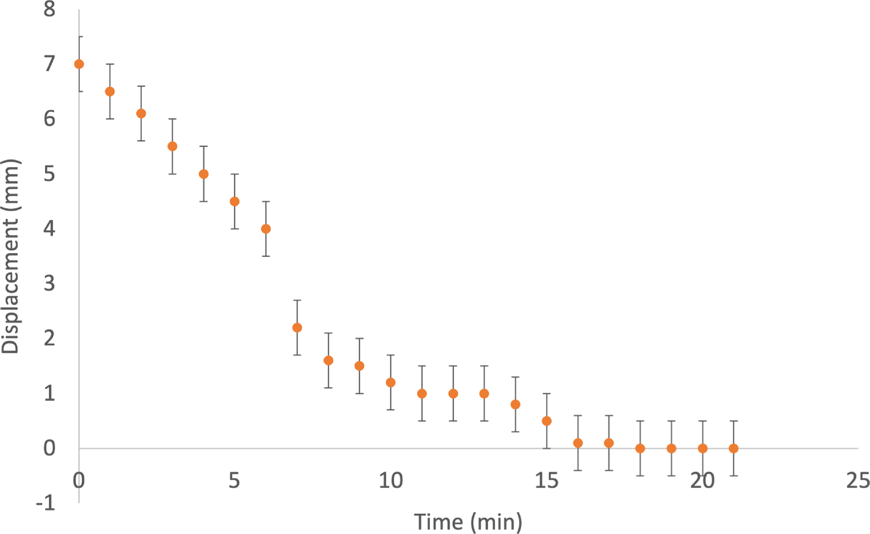
The folded-beam suspension was tested to demonstrate linear actuation. The PLA mechanism was able to lift a 0.1 kg mass from its initial (Fig. 8a) to final (Fig. 8b) position as the material dissolved: a vertical distance of approximately 7 mm (see Fig. 9). The plot also displays bars of uncertainty. This uncertainty was accumulated through measuring the displacement data from a ruler (
 $\pm$
0.5 mm for each data point). This test demonstrates that resorbable materials may be used to actuate mechanisms which require translational motion and may lift loads, the magnitude of which depends on the mechanism design.
Displacement versus time data received from the folded-beam suspension test, including bars of uncertainty. This data shows a clear, nonlinear increase in displacement over time as the inserts dissolved.

A finite-element analysis of the folded-beam suspension suggests that the design can support a greater force per unit deflection when other materials are used. The PLA exhibited stress relaxation under load, and the use of alternative materials could allow for additional force to be applied while avoiding stress relaxation. This mechanism thus achieved the desired effect of lifting the weight as the ice dissolved. This approach might be used in applications where delayed linear motion is required and active actuation is difficult.
Mechanism 3: Corrective bar
Mechanism 3 acts as a medical implant that can be placed in the chest cavity to correct a pectus excavatum deformity over time. Pectus excavatum is a deformity of the chest wall where the sternum is inset into the chest. While its underlying cause is not known, it is thought to be influenced by genetics [Reference Gurnett, Alaee, Bowcock, Kruse, Lenke, Bridwell, Kuklo, Luhmann and Dobbs51–Reference Chaput, Laguerre and Chavoin53]. One in every three to four hundred children is affected by the deformity, and males are at least four times more likely to be affected than females [Reference Fonkalsrud54–Reference Ravitch59]. Most commonly, its onset is prepubertal with varied rates of progression [Reference Farronato, Ghionzoli, Messineo, Politi, Divisi, Gonfiotti and Crisci60].
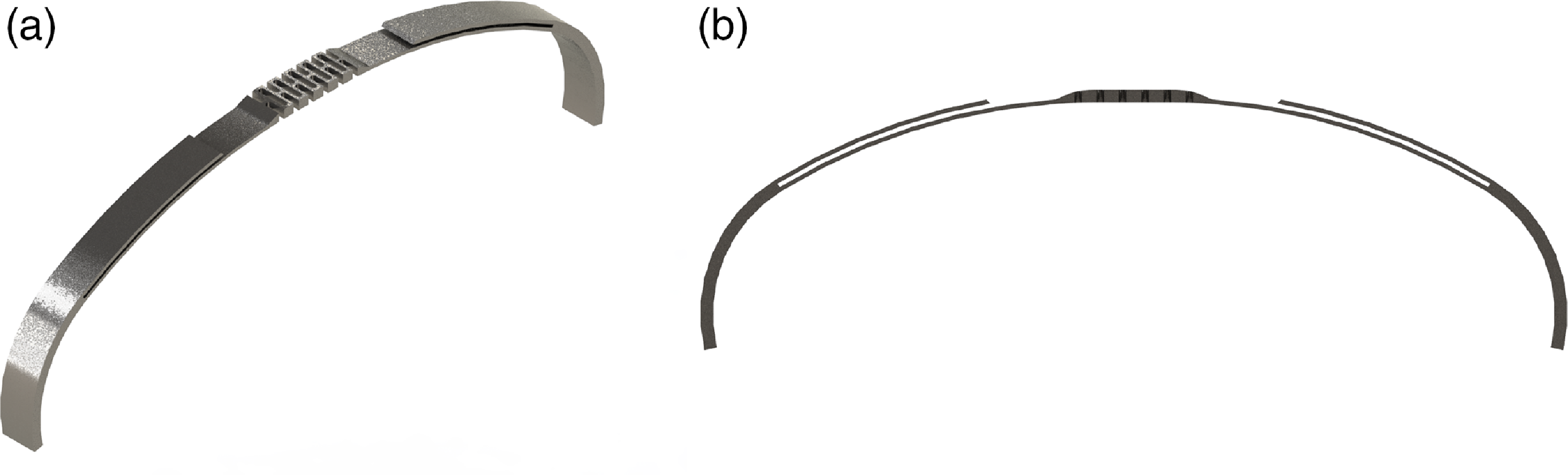
Rendering of the corrective bar similar to the one used in testing with (a) isometric view and (b) front view. While this render does not show the resorbable inserts, they would be placed in the slots visible between the bar and the offshoots.

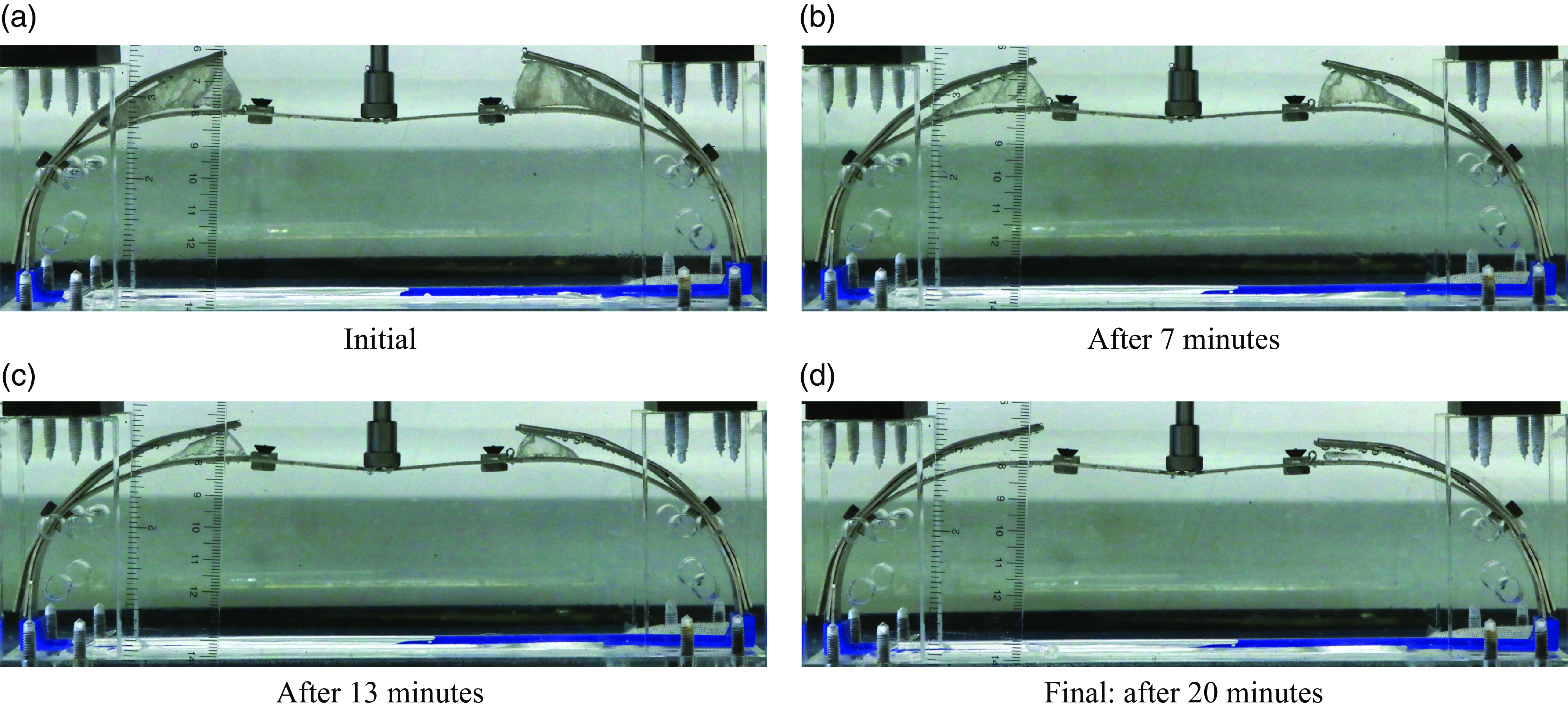
Pectus bar throughout resorption process from test 3: Aluminum mechanism with rock salt inserts. The rock salt is visible in (a) on each upper side of the insert.

In the past, pectus excavatum has been widely considered to have exclusively cosmetic or physiological adverse side effects, but recently many studies have proved that it can compress both the heart and the lungs between the sternum, spinal cord, and ribs. This cardiopulmonary compression can have effects varying from reduced exercise ability [Reference Chao, Jaroszewski, Kumar, Ewais, Appleton, Mookadam, Gotway and Naqvi61–Reference Sigalet, Montgomery and Harder65], to threatening the person’s life [Reference Chao, Jaroszewski, Kumar, Ewais, Appleton, Mookadam, Gotway and Naqvi61, Reference Ravitch66–Reference Nuss69]. The current procedure to correct pectus excavatum involves the placement of a curved metal bar inside the chest cavity, which forces the deformed sternum immediately into the corrected location [Reference Nuss, Obermeyer and Kelly26].
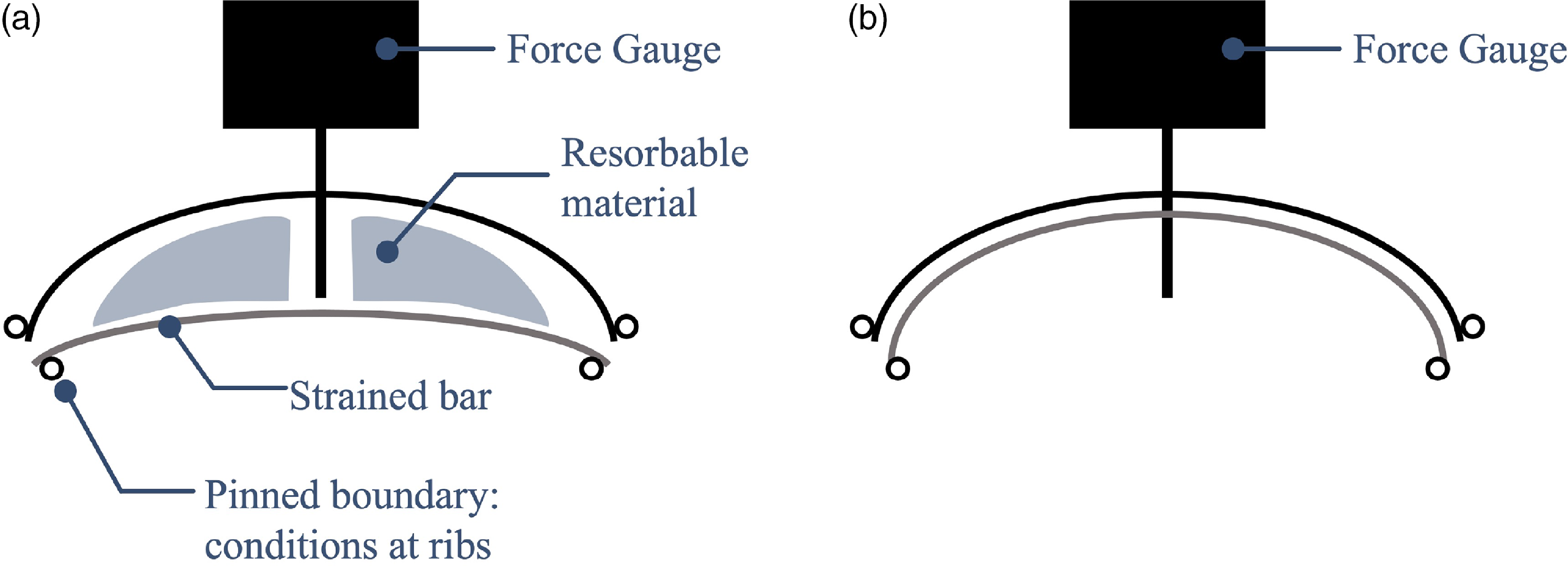
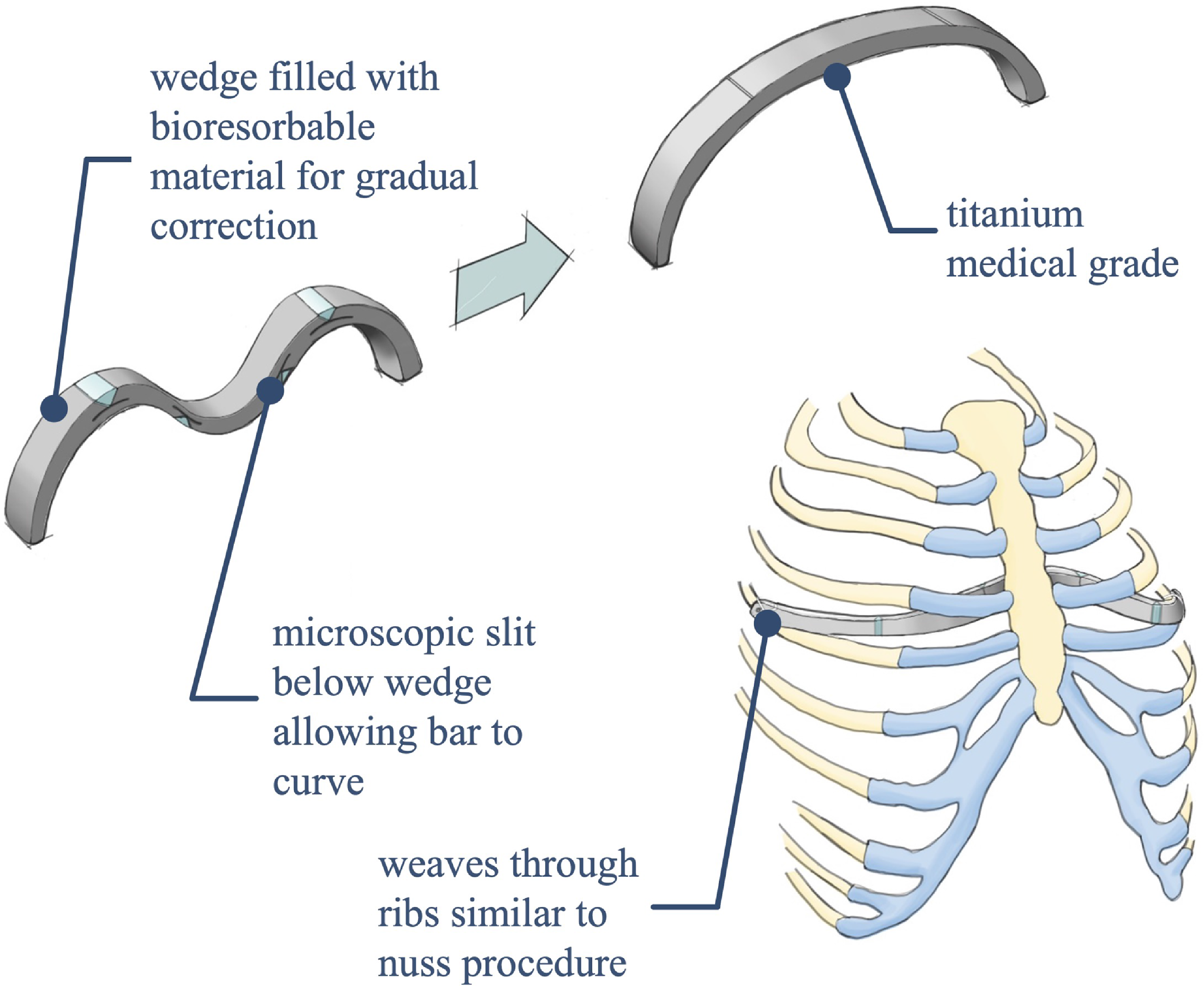
The corrective bar described in this work (a rendering of which is shown in Fig. 10) utilizes resorbable inserts and enables a gradual – and presumably less painful – correction of the deformity. Placing the resorbable inserts in compression in prescribed locations throughout the bar, as shown in Fig. 11, allows the bar to initially conform to the deformed shape of the sternum. As the materials dissolve, the stored strain energy in the bar forces the bar toward its initial configuration and redirects the force onto the sternum so that the sternum is gradually corrected (Fig. 12). This concept is shown relative to a ribcage in Fig. 13. Use of resorbable materials to activate this device allows for a gradual correction without requiring an external stimulus, as might be otherwise obtained through additional surgeries or in-patient visits.
Schematic illustrating the basic concept of Mechanism 3. (a) The linear springs have stored potential energy. (b) The potential energy is released as the resorbable material dissolves.

An initial conceptual design for the corrective bar. The design changed somewhat before the final iteration tested in this work, but the concepts of surgical insertion and gradual correction are the same.

Testing of Mechanism 3 was performed as follows: A corrective bar was manufactured out of aluminum, and the resorbable inserts were carved from rock salt for the test displayed in Fig. 11. A tank was filled with 5 gallons of 43
 $^{\circ }$
C water. The resorbable inserts were placed in their designated locations in the mechanism, which forced the center of the mechanism to a displaced location (see Fig. 11a). The mechanism was placed in a rig which fixed its ends and center and allowed use of a force gauge to measure the device’s force output over time. The rig and mechanism were then placed in the warm water to allow material dissolution to begin. A ruler was placed behind the mechanism to measure the mechanism’s displacement over time. Pictures of the mechanism’s actuation were taken once every 6 minutes to track resorption progress.
Figure 11 shows the aluminum corrective bar throughout material dissolution. This design would require modification before in vivo use but gives proof of concept. Because aluminum did not suffer from significant stress relaxation in the time of experimentation (unlike many polymers) and because of the aluminum’s greater elastic properties, it is more ideal for displaying the functionality of resorbable materials. There is, however, still a slight plastic deformation of the bar visible in 11d; the left side of the bar has not managed to return entirely to its initial position. This is likely because the bar had been used for several prior tests.
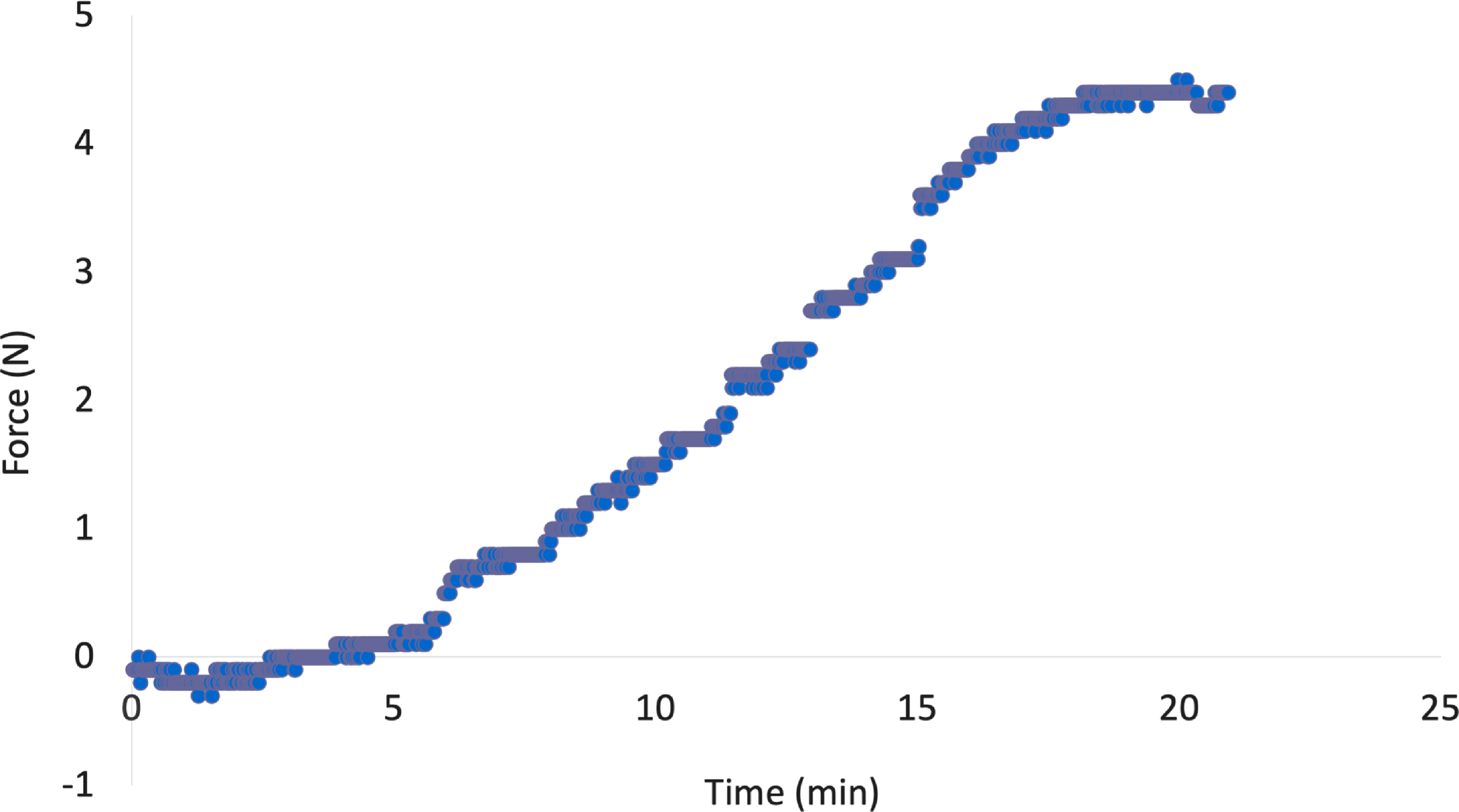
The corrective bar produced a maximum force output of approximately 4.5 N. Again, using different materials and mechanism designs would allow the mechanism to lift even heavier weights. Figure 14 shows that as the resorbable material dissolved, the force the bar exerted on the force gauge also increased. Such data could be used to create models to predict dissolution rate based on material properties, the insert’s dimensions and volume, force placed on the inserts, and characteristics of the surrounding environment [Reference Ciccone, Motz, Bentley and Tasto2, Reference Cutright, Perez, Beasley, Larson and Posey20]. The force gauge used has an uncertainty of
 $\pm$
0.1 N.
Force versus time data received from test 3. This data shows a clear increase in force over time as the inserts dissolve.

A finite-element analysis performed on the pectus bar model verified that the maximum force produced by the bar at this continuous deflection was approximately 5N. This verification makes it clear that the resorbable inserts are redirecting a portion of the force, and that once they have dissolved, the mechanism functions as it would without the inserts. This also serves as a proof of concept for the device, showing that it could perform a gradual correction of the deformity by applying greater and greater forces onto the sternum over time. The pectus bar test successfully demonstrated that resorbable materials may be used to actuate mechanisms which require more complex linear motion and may also generate force. Different material choice and mechanism design would be able to produce various linear deflections and forces.
Mechanism 4: Catapult
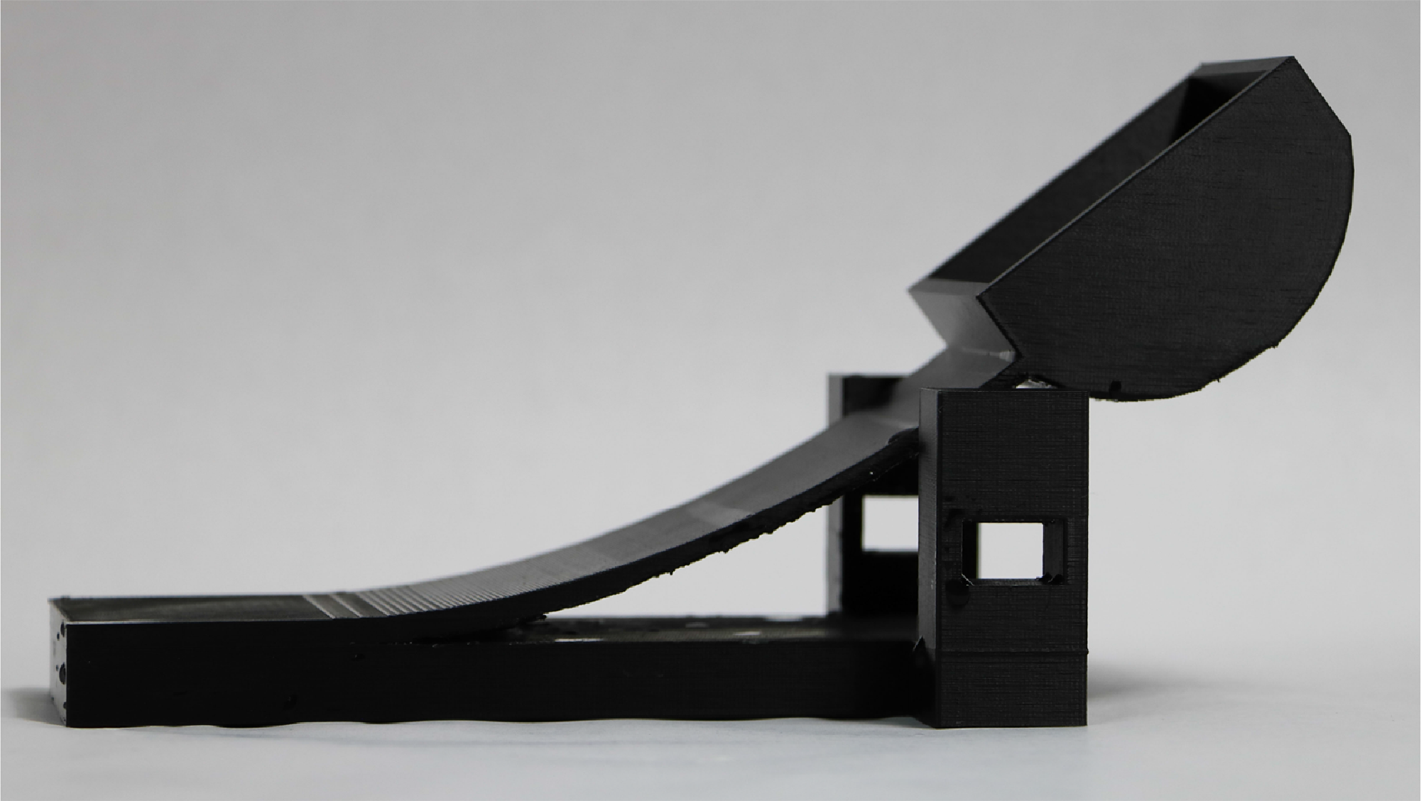
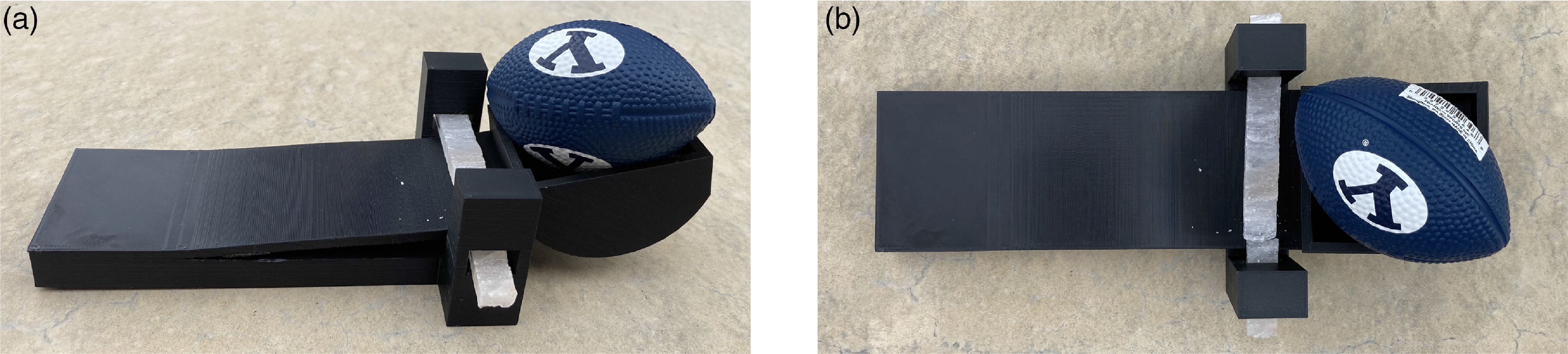
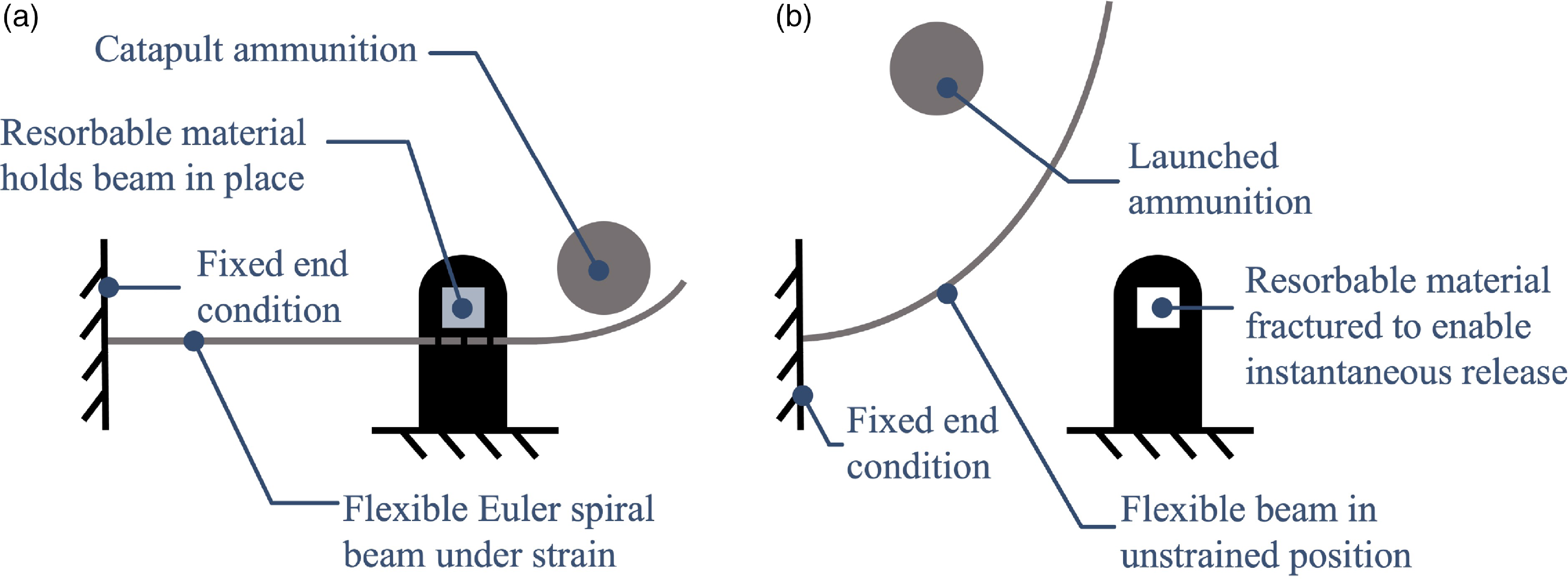
Mechanism 4 is used to demonstrate an instantaneous actuation application for resorbable materials. The catapult in Fig. 15 is designed from an Euler spiral to maximize energy potential of the compliant arm [Reference Ynchausti, Brown, Magleby, Bowden and Howell70, Reference Levien71]. The catapult is loaded with ammunition (in this case, a small foam American-style football) then locked using a resorbable material loaded in shear, as seen in Fig. 16. The material resorbs until it catastrophically fails, which releases the strain energy in the catapult arm, launching the football. This actuation process is also shown in Fig. 17.
The 3D-printed catapult in its relaxed state.

The catapult with the arm restrained by a bar of rock salt. (a) Angled view. (b) Top view.

Schematic illustrating the basic concept of Mechanism 4. (a) The Euler spiral beam is held under strain by the resorbable material. (b) When the resorbable material fractures, the strain energy is released and the ammunition is launched.

Testing of Mechanism 4 was performed as follows: The catapult was 3D-printed in PLA. A bar of rock salt was carved to the correct dimensions to fit in the lock. The catapult was loaded by displacing the arm and inserting the rock salt bar as a lock. The mechanism was then left in a tray of 43
 $^{\circ }$
C water. Once the rock salt had dissolved sufficiently, the strain energy stored in the catapult arm was enough to snap the bar, directly causing the material’s actuation (hence, the term “delayed instantaneous actuation”). A video of the actuation was taken so as to not miss the moment of actuation – the rock salt was under significant load due to the strain energy stored in the arm.
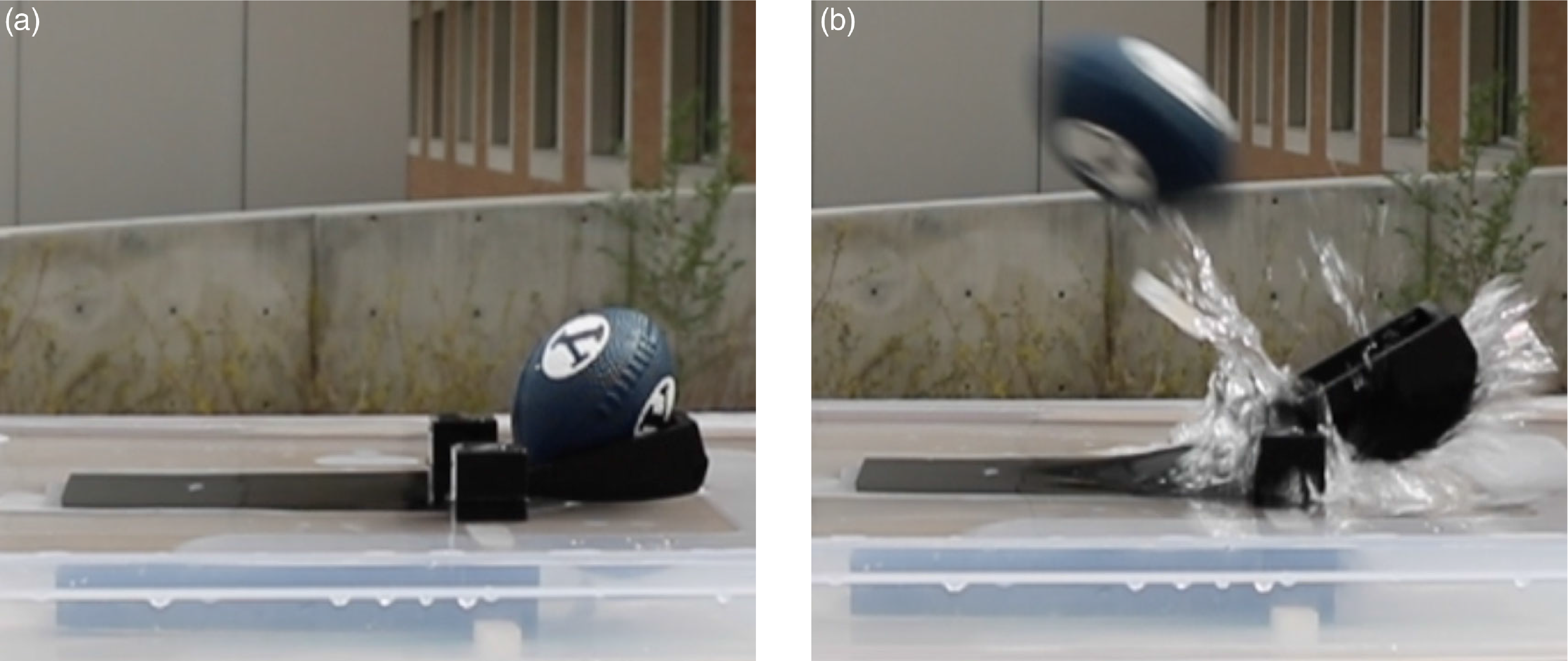
The catapult, the before-and-after for which may be seen in Fig. 18, provided proof of concept for instantaneous actuation via resorbable materials. The rock salt pin restraining the charged catapult arm shattered after 30 s: the moment of failure is shown in Fig. 18b, where a large portion of the bar was propelled away and may be seen below the football. The ammunition traveled approximately 3 m. It is likely that if the test had been performed in air instead of partially submerged in water, the catapult would have been able to produce a greater force and propel the ammunition farther. This design allowed the catapult to launch its ammunition with the strain energy stored in the arm instantaneously, rather than releasing the strain energy gradually as was done in the previous three tests.
Catapult test (a) before and (b) after the test. Rock salt was used as the resorbable material. Refer to Fig. 16 for a better visualization of the insert in (a); in (b), the shattered pieces of insert are visible behind the splash.

When utilizing resorbable materials for actuation and in cases where instantaneous actuation is required, a design similar to the one used here may therefore be a viable option.
4. Conclusion
Resorbable materials may be used as actuators in a variety of loading conditions and to cause either gradual and continuous or delayed instantaneous actuation, as demonstrated through the tests in this work. They are primarily beneficial in situations where the mechanism is required to actuate only once and have unique benefits in locations which are difficult to reach, as shown in Fig. 1. The time of actuation is based on size of material, temperature, volume, agitation of solution, and the choice of material [Reference Yang, Lee, Xue, Yan, Liu, Kang, Lee, Lee, Seo and Lu4, Reference Zhang, Jin, Han, Gao, Zeng, Hou and Zhang72]. Infinite combinations of these variables are possible and provide a large design space for applications. There are interesting open problems related to the effect of these variables on precision timing and related design performance metrics. This paper demonstrates the feasibility of the concept and lays the groundwork and justification for work detailing understanding of these parameters and their interactions. This tailorability of the materials makes them a viable and unique choice for mechanism actuation. Near-term applications are those that do not require precise control of timing, and future work could build on the work presented here to create a framework for achieving more precise control and timing. Designers may apply the principles presented here, which demonstrate the viability of actuating diverse mechanisms through the use of resorbable materials, to a variety of devices with new applications. In certain applications, the novelty of resorbable materials may allow for the creation of mechanisms whose motions were previously difficult or impossible.
Competing interests
The authors declare no competing interests exist.
Financial support
This work was supported by Zimmer Biomet and was performed in conjunction with Cincinnati Children’s Hospital Medical Center.
Ethical approval
Not applicable.
Author contributions
BP conceived and designed the majority of the studies, conducted testing, and wrote the article. BS and CR also helped in conception, design, and testing. SM and LH provided direction and aided in editing the article. VG provided invaluable medical expertise for the corrective bar. The authors would also like to especially thank Austin Martel for his assistance in preparing supplementary materials, Corinne Jackson for her assistance in early prototype and conceptual development, and Samantha Lewis for the concept sketch shown in Fig. 13.
Supplementary material
The supplementary material for this article can be found at https://doi.org/10.1017/S0263574723001534.