1. Introduction
The stability and breakdown of compressible swirling flows is an important problem for a variety of technological applications such as the aerodynamics of slender wings operating at high angles of incidence, combustion chambers, nozzles, and other high-speed flow devices where swirl has a dominant influence. The study of this problem may also shed light on complicated stability and breakdown phenomena that appear in numerous problems of geophysical and meteorological significance. In all of these cases the flow Mach number is not small and may reach values of 0.2 to 0.8. The effect of thermo–physical interactions in such flows is an essential part of the compressible flow dynamics and influences the conditions for the appearance of instabilities and transition (breakdown) phenomena.
Extensive literature is available on the fluid mechanics of vortex stability and breakdown of incompressible flows at low Mach numbers, including the reviews by Hall (Reference Hall1972), Leibovich (Reference Leibovich1984), Escudier (Reference Escudier1988), Althaus, Brücker & Weimer (Reference Althaus, Brücker and Weimer1995) and Sarpkaya (Reference Sarpkaya1995). Experiments show that the vortex breakdown phenomenon occurs when the swirl ratio
 ${\it\omega}$
, characterizing the upstream vortex flow, is above a certain critical value. Here,
 ${\it\omega}$
is defined as the ratio of the maximum circumferential velocity of the vortex to the centreline axial velocity. The breakdown state is characterized by an upstream strong swirling jet that experiences a significant flow expansion around a central recirculation (breakdown) zone and develops into a downstream weak and turbulent swirling wake flow. In addition, fine-scale three-dimensional vortical structures inside and around the breakdown zone are observed (Novak & Sarpkaya Reference Novak and Sarpkaya2000; Liang & Maxworthy Reference Liang and Maxworthy2005). The breakdown zone size and its location strongly depend on the swirl number, Reynolds number, chamber geometry and axial pressure gradient along the pipe.
Several possible explanations have been given for certain features of the problem. These include a jump transition from a supercritical upstream to a subcritical downstream state by Benjamin (Reference Benjamin1962), trapped solitary wave states by Randall & Leibovich (Reference Randall and Leibovich1973) and Leibovich & Kribus (Reference Leibovich and Kribus1990), the analogy to boundary layer separation by Hall (Reference Hall1972), the special breakdown solution by Keller, Egli & Exley (Reference Keller, Egli and Exley1985), the feedforward necessary mechanism for the generation of negative azimuthal vorticity and a stagnation (breakdown) point by Brown & Lopez (Reference Brown and Lopez1990), the bifurcation of multiple states in the numerical solutions of Beran & Culick (Reference Beran and Culick1992), Beran (Reference Beran1994), Lopez (Reference Lopez1994) and Buntine & Saffman (Reference Buntine and Saffman1995), and a vortex instability and breakdown process by Wang & Rusak (Reference Wang and Rusak1997a ) and Gallaire et al. (Reference Gallaire, Ruith, Meiburg, Chomaz and Huerre2006). However, a consistent description of the phenomenon is still an open subject of study. Specifically, all of these studies focused on incompressible flows and did not account for high-speed flows at higher Mach numbers.
This paper follows the theoretical framework of Wang & Rusak (Reference Wang and Rusak1997a ) for explaining and predicting the axisymmetric vortex breakdown process in incompressible vortex flows. The approach, employing the Euler formulation, examines the global dynamics of incompressible high-Reynolds-number axisymmetric swirling flows in a straight cylindrical pipe of finite length. The model considers the interaction of a vortex flow in a pipe, which is generated by a fixed-in-place and fixed-in-time vortex generator, with vorticity waves that propagate in the flow. The model mimics the imbalance between the inlet state and the outlet state that appears in a flow in a finite-length pipe. It also allows the inlet state a degree of freedom to develop a radial velocity due to the effect of the upstream influence of propagating disturbances in the flow. The results, established through a rigorous, nonlinear global analysis, provide a fundamental and nearly complete mathematical description of the dynamics and stability of axisymmetric swirling flows in pipes.
The analysis of Wang & Rusak (Reference Wang and Rusak1997a
) revealed the existence of three branches of steady vortex states, connected by two critical levels of swirl,
 ${\it\omega}_{0}$
and
 ${\it\omega}_{1}$
, where
 ${\it\omega}_{0}<{\it\omega}_{1}$
. The critical swirl
 ${\it\omega}_{1}$
is an extension for a finite-length pipe of Benjamin’s (Reference Benjamin1962) critical swirl and
 ${\it\omega}_{0}$
is an extension for a finite-length pipe of the special vortex breakdown state of Keller et al. (Reference Keller, Egli and Exley1985). The branch of columnar (parallel) vortex states is composed of absolutely stable states when
 ${\it\omega}<{\it\omega}_{0}$
, linearly stable states when
 ${\it\omega}_{0}<{\it\omega}<{\it\omega}_{1}$
and unstable states when
 ${\it\omega}>{\it\omega}_{1}$
. A branch of states connecting between the states at
 ${\it\omega}_{0}$
and
 ${\it\omega}_{1}$
is composed of unstable solitary waves. The branch of breakdown states starts from the swirl ratio
 ${\it\omega}_{0}$
and is an attractor of flow dynamics for
 ${\it\omega}>{\it\omega}_{0}$
. The theory shows that the vortex breakdown phenomenon is a necessary fast evolution from an initially near-columnar concentrated vortex flow to a lower-energy state describing a swirling flow around a large nearly stagnant breakdown zone that is open downstream. This evolution is the result of the interaction between azimuthal vorticity waves propagating upstream and the relatively fixed incoming vortex flow, which leads to a loss of stability of the base columnar state when the swirl ratio
 ${\it\omega}$
is above the critical level
 ${\it\omega}_{0}$
; see the extensive numerical simulations of Rusak et al. (Reference Rusak, Wang, Xu and Taylor2012) and Rusak & Wang (Reference Rusak and Wang2014). The fundamental critical states at
 ${\it\omega}_{0}$
and
 ${\it\omega}_{1}$
that lead to vortex instability and breakdown are calculated from a single ordinary differential equation that is governed by the inflow axial and circumferential speed profiles. The effects of the flow Reynolds number, inlet vorticity perturbations and pipe divergence or contraction on the critical swirl
 ${\it\omega}_{1}$
were studied in Wang & Rusak (Reference Wang and Rusak1997b
), Rusak (Reference Rusak1998), Rusak & Judd (Reference Rusak and Judd2001) and Rusak & Meder (Reference Rusak and Meder2004) respectively. It was found that these realistic effects form an imperfection in the bifurcation diagram of inviscid swirling flows in a straight pipe and modify the critical swirl,
 ${\it\omega}_{1}$
, of the incoming flow. Guided by the theory, the breakdown criteria of Q-vortices in a pipe were computed in Rusak, Whiting & Wang (Reference Rusak, Whiting and Wang1998) and showed agreement with the data of Leibovich (Reference Leibovich1984). Independently, Mattner, Joubert & Chong (Reference Mattner, Joubert and Chong2002) also found nice agreement between their measured breakdown states and the predictions of Rusak et al. (Reference Rusak, Whiting and Wang1998). Rusak & Lamb (Reference Rusak and Lamb1999) showed an agreement of predictions with measured data of breakdown location along leading-edge vortices above delta wings as a function of angle of attack.
The study of the effect of subsonic flow Mach number and compressibility on vortex stability and the dynamics toward a breakdown state is limited in scope. The experiment of Visbal & Gordnier (Reference Visbal and Gordnier1995) noted that increasing the Mach number would alleviate or delay vortex breakdown. Similarly, the numerical simulations of Kuruvila & Salas (Reference Kuruvila and Salas1990), Melville (Reference Melville1996) and Herrada, Prez-sabroid & Barrero (Reference Herrada, Prez-Sabroid and Barrero2003) found that within the subsonic flow regime transition to breakdown occurs at higher swirl levels as the Mach number is increased. On the other hand, the recent large-eddy simulations based on the compressible Navier–Stokes formulations by Luginsland & Kleiser (Reference Luginsland and Kleiser2015) of swirling nozzle-jet flows injected into a large domain of static fluid at a fixed Reynolds number (
 $Re=5000$
) found that the critical swirl for vortex breakdown to occur increases with decreasing Mach number. The difference between results of numerical simulations may be related to the special set-up operational conditions and scaling parameters employed in each simulation.
A first attempt to theoretically describe the dynamics and breakdown of compressible subsonic vortex flows at near-critical swirl levels is given in Rusak & Lee (Reference Rusak and Lee2002, Reference Rusak and Lee2004) and Rusak, Choi & Lee (Reference Rusak, Choi and Lee2007). A strong interaction between the convection of vorticity waves and the baroclinic effects, due to the coupling between swirl and temperature gradients, was demonstrated. These studies showed that the bifurcation diagram of compressible swirling flows is similar in nature to that of incompressible vortex flows. However, the critical swirl ratio
 ${\it\omega}_{1}$
(which is also a point of bifurcation of non-columnar states as well as a point of exchange of stability) is delayed to higher levels as the incoming flow Mach number is increased, similarly to the numerical simulation results of Herrada et al. (Reference Herrada, Prez-Sabroid and Barrero2003).
Renac, Sipp & Jacquin (Reference Renac, Sipp and Jacquin2007) extended the study by Rusak & Lee (Reference Rusak and Lee2002, Reference Rusak and Lee2004). They derived an asymptotic solution in the case of an isothermal plug flow with solid-body rotation. In the limit of low Mach number (
 $0\leqslant Ma_{0}\ll 1$
), it was shown that the critical swirl
 ${\it\omega}_{1}$
increases with
 $Ma_{0}$
as
 ${\it\omega}_{1,Ma_{0}=0}/\sqrt{1-Ma_{0}^{2}}$
, where
 ${\it\omega}_{1,Ma_{0}=0}$
is the critical swirl of the incompressible flow. It was also found that this result still holds when varying the thermodynamic properties of the flow or when considering vortex models different from the Batchelor vortex. Physically, compressibility slows down the phase and group velocities of axisymmetric Kelvin waves, thus decreasing the rotation contribution to flow criticality and damping the stretching mechanism that dominates the wave propagation in the incompressible flow limit.
The above theoretical results are limited to the description of the nature of near-columnar states, around the critical swirl
 ${\it\omega}_{1}$
. However, the global theory was not generalized to determine the influence of baroclinic effects and Mach number on the swirl level
 ${\it\omega}_{0}$
for the first appearance of vortex breakdown and on the size of breakdown states at swirl levels
 ${\it\omega}>{\it\omega}_{0}$
.
In this paper we generalize the theoretical foundation of Wang & Rusak (Reference Wang and Rusak1997a ) to determine the dynamics of compressible subsonic vortex flows in a finite-length straight circular pipe. The contributions of the paper are as follows.
-
(i) A new equation for the analysis of swirling flows is developed. This equation generalizes the classical Squire–Long equation to the case of compressible swirling flows. The equation reflects the complicated thermo–physical interaction between the azimuthal vorticity, stretching of vorticity by circulation gradients and the baroclinic effect resulting from entropy gradients. The baroclinic effect does not exist in the incompressible flow, and it is not trivial.
-
(ii) A global analysis framework is developed to study compressible flows with swirl. It includes a novel flow force condition for compressible swirling flows. This condition is also a non-trivial generalization of the incompressible flow force condition.
-
(iii) The computed results provide for the first time theoretical predictions for the first appearance of vortex breakdown as a function of the Mach number of the incoming flow and for the size of the breakdown zone as a function of the swirl level, Mach number and inlet flow temperature profile. The physical effect of the compressibility on the flow behaviour is significant although the bifurcation diagrams and dynamical behaviour may look similar to the incompressible flow case.
However, the present approach is limited to axisymmetric swirling flows in a pipe where the wall boundary layer is thin and attached and does not interact with the flow in the bulk. As the benchmark experiments of Novak & Sarpkaya (Reference Novak and Sarpkaya2000) show, high-
 $Re$
flows exhibit short-length spirals that burst into three-dimensional turbulence as well as wall boundary layer separation and interaction with the breakdown zone. Such situations are not mimicked by the present study. This gap in knowledge between the theory and the experimental situations must be further studied by extending the linear and nonlinear stability analyses of swirling flows to include the dynamics of three-dimensional perturbations and wall boundary layers.
The outline of this paper is as follows. A nonlinear partial differential equation for the solution of the flow stream function is developed in § 2 in terms of the inlet flow specific total enthalpy, specific entropy and circulation functions. The resulting nonlinear ordinary differential equation for the columnar (
 $x$
-independent) flow problem is formulated in § 3. Various types of solutions of this problem are discussed. A flow force condition is derived in § 4, relating the inlet and outlet states of steady-state swirling flows in a finite-length pipe. The bifurcation diagrams of steady states of swirling flows in the pipe with an inlet solid-body rotation flow and inlet Lamb–Oseen vortex, both with an axial plug flow and a constant temperature, are derived in § 5. The paper sheds additional light on the complex dynamics of compressible flows with swirl and vortex breakdown.
2. Mathematical model
We consider a swirling flow of a calorically perfect gas in a finite-length straight circular pipe. The gas thermo–physical specific heats,
 $C_{p}$
and
 $C_{v}$
, are assumed to be constant. The non-dimensional state, continuity, linear momentum and energy equations describing the development of a steady inviscid non-heat conducting and compressible flow of a perfect gas are given respectively by Thompson (Reference Thompson1982):
 $$\begin{eqnarray}\displaystyle \left.\begin{array}{@{}c@{}}\displaystyle p={\it\rho}T,\\ \displaystyle \boldsymbol{{\rm\nabla}}\boldsymbol{\cdot }({\it\rho}\boldsymbol{V})=0,\\ \displaystyle {\it\rho}\boldsymbol{V}\boldsymbol{\cdot }\boldsymbol{{\rm\nabla}}\boldsymbol{V}=-\frac{1}{{\it\gamma}Ma_{0}^{2}}\boldsymbol{{\rm\nabla}}p,\\ \displaystyle {\it\rho}\boldsymbol{V}\boldsymbol{\cdot }\boldsymbol{{\rm\nabla}}T=\frac{{\it\gamma}-1}{{\it\gamma}}\boldsymbol{V}\boldsymbol{\cdot }\boldsymbol{{\rm\nabla}}p.\end{array}\!\!\right\} & & \displaystyle\end{eqnarray}$$
Here,
 $T$
,
 ${\it\rho}$
and
 $p$
are the non-dimensional temperature, density and pressure, and
 $\boldsymbol{V}$
is the non-dimensional velocity vector. Non-dimensionalization is carried out with reference to the state of the inlet flow. Velocity is normalized with respect to the inlet flow centreline axial speed
 $\tilde{U} _{0}$
and lengths are normalized against the pipe inlet radius
 $\tilde{r}_{0}$
. Temperature, density and pressure are normalized with respect to the inlet flow centreline temperature
 $\tilde{T}_{0}$
, density
 $\tilde{{\it\rho}}_{0}$
and pressure
 $\tilde{p}_{0}$
; here,
 $\tilde{p}_{0}=\tilde{{\it\rho}}_{0}R\tilde{T}_{0}$
, where
 $R$
is the specific gas constant. Furthermore,
 ${\it\gamma}$
is the specific heat ratio and
 $Ma_{0}=\tilde{U} _{0}/\tilde{a}_{0}$
is the inlet axial flow Mach number, where
 $\tilde{a}_{0}=\sqrt{{\it\gamma}R\tilde{T}_{0}}$
is the isentropic acoustic speed at the reference state. In the present paper, we focus on flows with
 $0<Ma_{0}<1$
.
Using the flow linear momentum equation in (2.1), the Gibbs formula for a perfect gas in its non-dimensional form,
 $T\,\text{d}s={\it\gamma}\,\text{d}T-({\it\gamma}-1)\,\text{d}p/{\it\rho}$
(where
 $s$
is the non-dimensional specific entropy, scaled with the specific heat at constant volume
 $C_{v}$
), and the vector identity,
 $\boldsymbol{V}\boldsymbol{\cdot }\boldsymbol{{\rm\nabla}}\boldsymbol{V}=\boldsymbol{{\rm\nabla}}(\boldsymbol{V}\boldsymbol{\cdot }\boldsymbol{V}/2)-\boldsymbol{V}\times {\it\Omega}$
(where
 ${\it\Omega}=\boldsymbol{{\rm\nabla}}\times \boldsymbol{V}$
is the non-dimensional vorticity vector scaled by
 $\tilde{U} _{0}/\tilde{r}_{0}$
), Crocco’s formula is found (Thompson Reference Thompson1982):
 $$\begin{eqnarray}({\it\gamma}-1)Ma_{0}^{2}(\boldsymbol{V}\times {\it\Omega})=\boldsymbol{{\rm\nabla}}H-\frac{1}{{\it\gamma}}T\boldsymbol{{\rm\nabla}}s,\end{eqnarray}$$
where
 $H$
is the non-dimensional specific total enthalpy (scaled with the specific heat at constant pressure
 $C_{p}$
and the temperature
 $T_{0}$
) and is given by
 $H=T+({\it\gamma}-1)Ma_{0}^{2}(\boldsymbol{V}\boldsymbol{\cdot }\boldsymbol{V})/2$
. From the energy and linear momentum equation in (2.1), we find that
 $$\begin{eqnarray}{\it\rho}\boldsymbol{V}\boldsymbol{\cdot }\boldsymbol{{\rm\nabla}}H=0\end{eqnarray}$$
and, from the energy equation and the Gibbs formula, we find that
 $$\begin{eqnarray}{\it\rho}\boldsymbol{V}\boldsymbol{\cdot }\boldsymbol{{\rm\nabla}}s=0.\end{eqnarray}$$
This means that the specific total enthalpy and the specific entropy are constant along a streamline.
We consider the case of an axisymmetric flow in a cylindrical coordinate system
 $(x,r,{\it\theta})$
, where the
 $x$
-axis is along the pipe centreline,
 $0\leqslant x\leqslant x_{0}$
,
 $r$
is the nondimensional radial distance from the centreline,
 $0\leqslant r\leqslant 1$
, and
 ${\it\theta}$
is the azimuthal angle,
 $0\leqslant {\it\theta}<2{\rm\pi}$
. The corresponding axial velocity is
 $w$
, the circumferential velocity is
 $v$
and the radial velocity is
 $u$
, and the continuity equation in (2.1) is
 $$\begin{eqnarray}({\it\rho}ru)_{r}+({\it\rho}rw)_{x}=0.\end{eqnarray}$$
From (2.5), a stream function
 ${\it\Psi}(x,y)$
is defined, where
 $y=r^{2}/2$
is the Stokes classical coordinate for flow problems in cylindrical coordinates,
 $0\leqslant y\leqslant 1/2$
,
 $u=-{\it\Psi}_{x}/({\it\rho}\sqrt{2y})$
and
 $w={\it\Psi}_{y}/{\it\rho}$
. Moreover, the circumferential momentum equation in (2.1) is
 $$\begin{eqnarray}\displaystyle {\it\rho}u(rv)_{r}+{\it\rho}w(rv)_{x}=0 & & \displaystyle\end{eqnarray}$$
or
 $$\begin{eqnarray}\displaystyle -{\it\Psi}_{x}(rv)_{y}+{\it\Psi}_{y}(rv)_{x}=0. & & \displaystyle\end{eqnarray}$$
Equation (2.7) shows that the circulation function
 $K=rv$
is given by
 $K=K({\it\Psi})$
. This means that the circulation function is constant along a
 ${\it\Psi}=\text{constant}$
line. In addition, (2.3) and (2.4) become respectively
 $$\begin{eqnarray}\displaystyle & \displaystyle {\it\rho}uH_{r}+{\it\rho}wH_{x}=0, & \displaystyle\end{eqnarray}$$
 $$\begin{eqnarray}\displaystyle & \displaystyle {\it\rho}us_{r}+{\it\rho}ws_{x}=0 & \displaystyle\end{eqnarray}$$
 $$\begin{eqnarray}\displaystyle \left.\begin{array}{@{}c@{}}\displaystyle -{\it\Psi}_{x}H_{y}+{\it\Psi}_{y}H_{x}=0,\\ \displaystyle -{\it\Psi}_{x}s_{y}+{\it\Psi}_{y}s_{x}=0.\end{array}\!\!\right\} & & \displaystyle\end{eqnarray}$$
We find that
 $$\begin{eqnarray}H=H({\it\Psi})\quad \text{and}\quad s=s({\it\Psi}).\end{eqnarray}$$
This means that the total enthalpy and entropy are constant along a
 ${\it\Psi}=\text{constant}$
line.
The
 $x$
-component of Crocco’s equation (2.2) is
 $({\it\gamma}-1)Ma_{0}^{2}(u{\it\eta}-v{\it\zeta})=H_{x}-(1/{\it\gamma})Ts_{x}$
, where the radial and circumferential components of the non-dimensional vorticity are
 ${\it\zeta}=-v_{x}=-(1/\sqrt{2}y)K_{x}$
and
 ${\it\eta}=u_{x}-w_{r}=u_{x}-\sqrt{2y}w_{y}$
respectively. With
 $v=K/\sqrt{2y}$
, we find that
 $$\begin{eqnarray}\displaystyle \left.\begin{array}{@{}c@{}}\displaystyle ({\it\gamma}-1)Ma_{0}^{2}u\left(u_{x}-\sqrt{2y}w_{y}\right)=H_{x}-({\it\gamma}-1)Ma_{0}^{2}\frac{KK_{x}}{2y}-\frac{1}{{\it\gamma}}Ts_{x}\quad \text{or }\\ \displaystyle -({\it\gamma}-1)Ma_{0}^{2}\frac{{\it\Psi}_{x}}{{\it\rho}\sqrt{2y}}\left(u_{x}-\sqrt{2y}w_{y}\right)\hspace{96.0pt}\\ \displaystyle \hspace{12.0pt}=\left[H^{\prime }({\it\Psi})-({\it\gamma}-1)Ma_{0}^{2}\frac{KK^{\prime }({\it\Psi})}{2y}-\frac{1}{{\it\gamma}}Ts^{\prime }({\it\Psi})\right]{\it\Psi}_{x}\quad \text{or }\end{array}\!\!\right\}\hspace{24.0pt} & & \displaystyle\end{eqnarray}$$
 $$\begin{eqnarray}\displaystyle \displaystyle ({\it\gamma}-1)Ma_{0}^{2}\left[\frac{1}{{\it\rho}}\left(\frac{{\it\Psi}_{y}}{{\it\rho}}\right)_{y}+\frac{1}{2y{\it\rho}}\left(\frac{{\it\Psi}_{x}}{{\it\rho}}\right)_{x}\right]=H^{\prime }({\it\Psi})-({\it\gamma}-1)Ma_{0}^{2}\frac{KK^{\prime }({\it\Psi})}{2y}-\frac{1}{{\it\gamma}}Ts^{\prime }({\it\Psi}). & & \displaystyle \nonumber\\ \displaystyle \hspace{-20.00003pt} & & \displaystyle\end{eqnarray}$$
 $(\,)^{\prime }$
represents the derivative with respect to
 ${\it\Psi}$
. The right-hand side of (2.13) represents the azimuthal vorticity in an axisymmetric compressible flow while the left-hand side includes production terms of azimuthal vorticity related to the derivatives of total enthalpy, circulation and entropy.
Equation (2.13) is a new partial differential equation (PDE) for the solution of
 ${\it\Psi}(x,y)$
. It generalizes the classical Squire–Long equation (Long Reference Long1953; Squire Reference Squire, Batchelor and Davies1956) for steady incompressible swirling flows to the case of steady compressible swirling flows. In (2.13), the non-dimensional density
 ${\it\rho}$
is computed from the specific entropy definition for a perfect gas,
 $s=\ln (T/{\it\rho}^{{\it\gamma}-1})$
, i.e.
 ${\it\rho}=[T/\text{exp}(s({\it\Psi}))]^{1/({\it\gamma}-1)}$
, where the non-dimensional temperature
 $T$
is found from
 $T=H({\it\Psi})-(({\it\gamma}-1)Ma_{0}^{2}/2)(u^{2}+w^{2}+K^{2}({\it\Psi})/2y)$
with
 $u=-({\it\Psi}_{x})/{\it\rho}\sqrt{2y}$
,
 $w={\it\Psi}_{y}/{\it\rho}$
. The solution of (2.13) assumes that the functions
 $K({\it\Psi})$
,
 $H({\it\Psi})$
and
 $s({\it\Psi})$
are given; for example, they are determined by the inlet flow conditions to the pipe.
For a flow in a finite-length straight circular pipe of non-dimensional length
 $x_{0}$
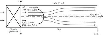
, we consider the following boundary conditions; see the set-up in figure 1. At the pipe inlet at
 $x=0$
, we assume that the profiles of the axial velocity, the circumferential velocity, the axial derivative of the radial velocity and the temperature are given by
 $$\begin{eqnarray}\displaystyle w(0,y)=w_{0}(y),\quad v(0,y)={\it\omega}v_{0}(y),\quad \hspace{-0.5pt}u_{x}(0,y)=0,\quad \hspace{-0.5pt}T(0,y)=T_{0}(y)\quad \hspace{-0.5pt}\text{for }0\leqslant y\leqslant 1/2.\quad \hspace{-20.00003pt} & & \displaystyle \nonumber\\ \displaystyle & & \displaystyle\end{eqnarray}$$
Here,
 ${\it\omega}$
is the swirl ratio of the incoming flow, as defined in the introduction. These inlet conditions may describe a compressible swirling flow that was generated by a vortex generator ahead of the pipe at continuous and steady operation. The inlet conditions on the radial velocity allow the inlet state a degree of freedom to develop a radial velocity to account for the upstream influence of propagating disturbances in the flow.
Schematic diagram of a compressible swirling flow in a pipe.

At the pipe outlet at
 $x=x_{0}$
, we assume
 $$\begin{eqnarray}u(x_{0},y)=0\quad \text{for }0\leqslant y\leqslant 1/2.\end{eqnarray}$$
This outlet condition may represent the case of a flow in a long pipe where the flow settles on a parallel (columnar) state.
Along the pipe centreline at
 $y=0$
, we assume the symmetry condition,
 ${\it\Psi}(x,0)=0$
for
 $0\leqslant x\leqslant x_{0}$
, and along the pipe wall at
 $y=1/2$
, we assume a constant value of
 ${\rm\Psi}$
,
 ${\it\Psi}(x,1/2)={\it\Psi}_{w}\equiv \int _{0}^{1/2}{\it\rho}_{0}(y)w_{0}(y)\,\text{d}y$
for
 $0\leqslant x\leqslant x_{0}$
.
The functions
 $K({\it\Psi})$
,
 $H({\it\Psi})$
and
 $s({\it\Psi})$
are defined in the range of
 $0\leqslant {\it\Psi}\leqslant {\it\Psi}_{w}$
. In addition, to accommodate possible solutions with separation zones, we assume that
 $$\begin{eqnarray}\displaystyle \left.\begin{array}{@{}c@{}}\displaystyle K({\it\Psi})=K(0)=0,\quad H({\it\Psi})=H(0)=H_{0},\quad s({\it\Psi})=s(0)=s_{0},\\ \displaystyle K^{\prime }({\it\Psi})=H^{\prime }({\it\Psi})=s^{\prime }({\it\Psi})=0\end{array}\!\!\right\} & & \displaystyle\end{eqnarray}$$
when
 ${\it\Psi}<0$
, and
 $$\begin{eqnarray}\displaystyle \left.\begin{array}{@{}c@{}}\displaystyle K({\it\Psi})=K({\it\Psi}_{w})=K_{w},\quad H({\it\Psi})=H({\it\Psi}_{w})=H_{w},\quad s({\it\Psi})=s({\it\Psi}_{w})=s_{w},\\ \displaystyle K^{\prime }({\it\Psi})=H^{\prime }({\it\Psi})=s^{\prime }({\it\Psi})=0\end{array}\!\!\right\} & & \displaystyle\end{eqnarray}$$
when
 ${\it\Psi}>{\it\Psi}_{w}$
.
A base solution of the PDE (2.13) with the assumed boundary conditions for all
 ${\it\gamma}$
,
 $Ma_{0}$
and
 ${\it\omega}$
is the columnar flow state given by
 $$\begin{eqnarray}\displaystyle \left.\begin{array}{@{}c@{}}\displaystyle w(x,y)=w_{0}(y),\quad v(x,y)={\it\omega}v_{0}(y),\quad u(x,y)=0,\\ \displaystyle T(x,y)=T_{0}(y)\quad \text{for }0\leqslant x\leqslant x_{0}\text{ and }0\leqslant y\leqslant 1/2.\end{array}\!\!\right\} & & \displaystyle\end{eqnarray}$$
This solution is denoted as the type 0 solution of the swirling flow problem in a finite-length straight circular pipe. We seek to determine the possible existence of additional steady states of swirling flows in the finite-length straight circular pipe with the same
 ${\it\gamma}$
,
 $Ma_{0}$
,
 ${\it\omega}$
,
 $H({\it\Psi})$
,
 $K({\it\Psi})$
,
 $s({\it\Psi})$
and assumed boundary conditions. In all the cases in this paper,
 ${\it\gamma}=1.4$
is assumed (which represents the case of air at standard atmospheric conditions).
3. The columnar flow problem
A flow is defined as columnar when it is
 $x$
-independent, i.e.
 $u=0$
, and
 ${\it\Psi}={\it\Psi}(y)$
. It should be noted that for a long pipe the outlet state of the solution of the PDE (2.13) is a columnar state. We consider a base columnar state where
 $w=w_{0}(y)$
,
 $v={\it\omega}v_{0}(y)$
,
 $T=T_{0}(y)$
,
 $p=p_{0}(y)$
,
 ${\it\rho}={\it\rho}_{0}(y)$
. Then, from the radial momentum equation for a columnar state,
 $p_{0r}={\it\gamma}Ma_{0}^{2}{\it\rho}_{0}({\it\omega}^{2}v_{0}^{2}/r)$
. Together with the non-dimensional equation of state we find that
 $$\begin{eqnarray}\frac{p_{0y}}{p_{0}}={\it\gamma}Ma_{0}^{2}{\it\omega}^{2}\frac{v_{0}^{2}(y)}{2yT_{0}(y)}.\end{eqnarray}$$
With the condition
 $p_{0}(0)=1$
we find that
 $$\begin{eqnarray}\displaystyle p_{0}(y)=\exp \left[\frac{{\it\gamma}Ma_{0}^{2}{\it\omega}^{2}}{2}\int _{0}^{y}\frac{v_{0}^{2}(\bar{y})}{\bar{y}T_{0}(\bar{y})}\,\text{d}\bar{y}\right] & & \displaystyle\end{eqnarray}$$
and
 $$\begin{eqnarray}\displaystyle {\it\rho}_{0}(y)=\frac{1}{T_{0}(y)}\exp \left[\frac{{\it\gamma}Ma_{0}^{2}{\it\omega}^{2}}{2}\int _{0}^{y}\frac{v_{0}^{2}(\bar{y})}{\bar{y}T_{0}(\bar{y})}\,\text{d}\bar{y}\right]. & & \displaystyle\end{eqnarray}$$
Then, from
 $w={\it\Psi}_{y}/{\it\rho}$
and (3.3) we can compute
 $$\begin{eqnarray}{\it\Psi}(y)=\int _{0}^{y}{\it\rho}_{0}(\bar{y})w_{0}(\bar{y})\,\text{d}\bar{y}.\end{eqnarray}$$
This function can be inverted such that
 $y=y({\it\Psi})$
. Moreover, we can compute
 $K={\it\omega}\sqrt{2y}v_{0}(y)$
and then
 $$\begin{eqnarray}\displaystyle K({\it\Psi})={\it\omega}\sqrt{2y({\it\Psi})}v_{0}(y({\it\Psi})). & & \displaystyle\end{eqnarray}$$
From the definition of
 $H$
,
 $$\begin{eqnarray}\displaystyle H=T_{0}(y)+\frac{({\it\gamma}-1)Ma_{0}^{2}}{2}({\it\omega}^{2}v_{0}^{2}(y)+w_{0}^{2}(y)), & & \displaystyle\end{eqnarray}$$
we find that
 $$\begin{eqnarray}\displaystyle H({\it\Psi})=T_{0}(y({\it\Psi}))+\frac{({\it\gamma}-1)Ma_{0}^{2}}{2}({\it\omega}^{2}v_{0}^{2}(y({\it\Psi}))+w_{0}^{2}(y({\it\Psi}))). & & \displaystyle\end{eqnarray}$$
Moreover, from the definition of
 $s$
for a calorically perfect gas,
 $$\begin{eqnarray}\displaystyle s=\ln \left(\frac{T_{0}}{{\it\rho}_{0}^{{\it\gamma}-1}}\right), & & \displaystyle\end{eqnarray}$$
we find that
 $$\begin{eqnarray}\displaystyle s=\ln \left[\frac{T_{0}(y)}{({\it\rho}_{0}(y))^{{\it\gamma}-1}}\right]=\ln \left[T_{0}^{{\it\gamma}}(y)\left(\exp \left[\frac{{\it\gamma}Ma_{0}^{2}{\it\omega}^{2}}{2}\int _{0}^{y}\frac{v_{0}^{2}(\bar{y})}{\bar{y}T_{0}(\bar{y})}\,\text{d}\bar{y}\right]\right)^{-({\it\gamma}-1)}\right], & & \displaystyle\end{eqnarray}$$
and then
 $$\begin{eqnarray}s({\it\Psi})={\it\gamma}\left[\ln (T_{0}(y({\it\Psi})))-\frac{({\it\gamma}-1)Ma_{0}^{2}{\it\omega}^{2}}{2}\int _{0}^{y({\it\Psi})}\frac{v_{0}^{2}(\bar{y})}{\bar{y}T_{0}(\bar{y})}\,\text{d}\bar{y}\right].\end{eqnarray}$$
From (3.6) to (3.10), we can compute the derivatives
 $$\begin{eqnarray}K^{\prime }({\it\Psi})=\frac{\text{d}K}{\text{d}y}\frac{\text{d}y}{\text{d}{\it\Psi}}=\frac{{\it\omega}(\sqrt{2y}v_{0}(y))_{y}}{{\it\rho}_{0}(y)w_{0}(y)}=\frac{{\it\omega}\left[\left(\sqrt{2y}v_{0}(y)\right)_{y}\right]_{y=y({\it\Psi})}T_{0}(y({\it\Psi}))}{w_{0}(y({\it\Psi}))\exp \left[\displaystyle \frac{{\it\gamma}Ma_{0}^{2}{\it\omega}^{2}}{2}\int _{0}^{y({\it\Psi})}\frac{v_{0}^{2}(\bar{y})}{\bar{y}T_{0}(\bar{y})}\,\text{d}\bar{y}\right]},\end{eqnarray}$$
 $$\begin{eqnarray}\displaystyle H^{\prime }({\it\Psi}) & \hspace{-3.0pt}= & \displaystyle \hspace{-3.0pt}\frac{\text{d}H}{\text{d}y}\frac{\text{d}y}{\text{d}{\it\Psi}}=\frac{T_{0y}+({\it\gamma}-1)Ma_{0}^{2}({\it\omega}^{2}v_{0}v_{0y}+w_{0}w_{0y})}{{\it\rho}_{0}(y)w_{0}(y)}\nonumber\\ \displaystyle & \hspace{-3.0pt}= & \displaystyle \hspace{-3.0pt}T_{0}(y({\it\Psi}))\frac{T_{0y}(y({\it\Psi}))\hspace{-1.0pt}+\hspace{-1.0pt}({\it\gamma}-1)Ma_{0}^{2}({\it\omega}^{2}v_{0}(y({\it\Psi}))v_{0y}(y({\it\Psi}))\hspace{-1.0pt}+\hspace{-1.0pt}w_{0}(y({\it\Psi}))w_{0y}(y({\it\Psi})))}{w_{0}(y({\it\Psi}))\exp \left[\displaystyle \frac{{\it\gamma}Ma_{0}^{2}{\it\omega}^{2}}{2}\int _{0}^{y({\it\Psi})}\frac{v_{0}^{2}(\bar{y})}{\bar{y}T_{0}(\bar{y})}\,\text{d}\bar{y}\right]}\nonumber\\ \displaystyle & & \displaystyle\end{eqnarray}$$
and
 $$\begin{eqnarray}s^{\prime }({\it\Psi})=\frac{\text{d}s}{\text{d}y}\frac{\text{d}y}{\text{d}{\it\Psi}}=\frac{{\it\gamma}\left[T_{0y}(y({\it\Psi}))-({\it\gamma}-1)Ma_{0}^{2}{\it\omega}^{2}\displaystyle \frac{v_{0}^{2}(y({\it\Psi}))}{2y({\it\Psi})}\right]}{w_{0}(y({\it\Psi}))\exp \left[\displaystyle \frac{{\it\gamma}Ma_{0}^{2}{\it\omega}^{2}}{2}\int _{0}^{y({\it\Psi})}\frac{v_{0}^{2}(\bar{y})}{\bar{y}T_{0}(\bar{y})}\,\text{d}\bar{y}\right]}.\end{eqnarray}$$
Equation (2.13) becomes in the columnar flow case an ordinary differential equation (ODE),
 $$\begin{eqnarray}({\it\gamma}-1)Ma_{0}^{2}\frac{1}{{\it\rho}}\left(\frac{{\it\Psi}_{y}}{{\it\rho}}\right)_{y}=H^{\prime }({\it\Psi})-({\it\gamma}-1)Ma_{0}^{2}\frac{KK^{\prime }({\it\Psi})}{2y}-\frac{1}{{\it\gamma}}Ts^{\prime }({\it\Psi}),\end{eqnarray}$$
where the various functions of
 ${\it\Psi}$
are defined in (3.5) and (3.11)–(3.13). Moreover,
 $$\begin{eqnarray}\displaystyle & \displaystyle T=H({\it\Psi})-\frac{({\it\gamma}-1)Ma_{0}^{2}}{2}\left(\left(\frac{{\it\Psi}_{y}}{{\it\rho}}\right)^{2}+\frac{K^{2}({\it\Psi})}{2y}\right), & \displaystyle\end{eqnarray}$$
 $$\begin{eqnarray}\displaystyle & \displaystyle {\it\rho}=\left(\frac{H({\it\Psi})-\displaystyle \frac{({\it\gamma}-1)Ma_{0}^{2}}{2}\left(w^{2}+\frac{K^{2}({\it\Psi})}{2y}\right)}{\exp (s({\it\Psi}))}\right)^{1/({\it\gamma}-1)}. & \displaystyle\end{eqnarray}$$
 $w={\it\Psi}_{y}/{\it\rho}$
and then (3.14) is equivalent to the following system of two first-order nonlinear ODEs in terms of
 $w(y)$
and
 ${\it\Psi}(y)$
:
 $$\begin{eqnarray}\displaystyle \left.\begin{array}{@{}c@{}}\displaystyle w_{y}=\frac{1}{({\it\gamma}-1)Ma_{0}^{2}}{\it\rho}\left(H^{\prime }({\it\Psi})-({\it\gamma}-1)Ma_{0}^{2}\frac{K({\it\Psi})K^{\prime }({\it\Psi})}{2y}-\frac{1}{{\it\gamma}}Ts^{\prime }({\it\Psi})\right),\\ \displaystyle {\it\Psi}_{y}={\it\rho}w,\end{array}\!\!\right\} & & \displaystyle\end{eqnarray}$$
with
 $T$
and
 ${\it\rho}$
from (3.15) and (3.16), and with boundary conditions
 $$\begin{eqnarray}{\it\Psi}(0)=0,\quad {\it\Psi}(1/2)={\it\Psi}_{w}=\int _{0}^{1/2}{\it\rho}_{0}(y)w_{0}(y)\,\text{d}y.\end{eqnarray}$$
A trivial solution of the columnar problem (3.17) and (3.18) is the base state,
 $w=w_{0}(y)$
,
 $v={\it\omega}v_{0}(y)$
,
 $T=T_{0}(y)$
, with
 $p=p_{0}(y)$
and
 ${\it\rho}={\it\rho}_{0}(y)$
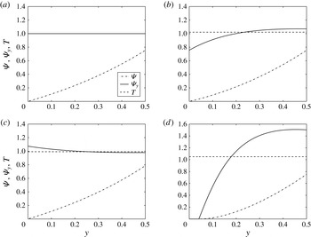
given by (3.2) and (3.3), and it is denoted as a type 0 solution of the columnar flow problem. See an example of a type 0 solution in figure 2(a) for the case of a solid-body rotation (
 $v_{0}(y)=\sqrt{2y}$
) with a uniform axial velocity
 $(w_{0}(y)=1)$
and a constant temperature
 $(T_{0}(y)=1)$
at
 $Ma_{0}=0.5$
and
 ${\it\omega}=2.1$
. The work of Wang & Rusak (Reference Wang and Rusak1997a
) for incompressible swirling flows shows that additional solutions of the nonlinear columnar flow problem exist when the swirl ratio,
 ${\it\omega}$
, is increased above a certain value. Thereby, it shows the existence of multiple solutions of the PDE (2.13) with (2.14) and (2.15) and the appearance of vortex breakdown states in the limit of
 $Ma_{0}=0$
. Similar multiple solutions and breakdown states appear in the compressible flow case.
Solutions of the columnar flow problem for a base solid-body rotation flow with a uniform axial velocity and a constant temperature at
 $Ma_{0}=0.5$
: (a) type 0 (base columnar state) at
 ${\it\omega}=2.1$
, (b) type 1 (decelerated flow around the centreline) at
 ${\it\omega}=2.1$
, (c) type 2 (accelerated flow around the centreline) at
 ${\it\omega}=2.2$
and (d) type 3 (breakdown state) at
 ${\it\omega}=2.1$
.

The system (3.17) and (3.18) is solved numerically using a fourth-order Runge–Kutta ODE integration scheme. We find that at each subsonic Mach number there exist three additional types of solutions of the columnar problem (3.17) and (3.18). In the type 1 solution,
 $0<w(0)<w_{0}(0)$
and, for given
 $Ma_{0}$
and
 ${\it\omega}$
, the solution is found by iterations until
 $w(0)$
is converged. In the type 2 solution,
 $w(0)>w_{0}(0)$
and again, for given
 $Ma_{0}$
and
 ${\it\omega}$
, the solution is again found by iterations until
 $w(0)$
is converged. In the type 3 solution,
 ${\it\Psi}=w=0$
for a range
 $0\leqslant y\leqslant y_{0}$
and, for given
 $Ma_{0}$
and
 ${\it\omega}$
, the solution is found by iterations until
 $y_{0}$
is converged.
Representative examples of type 1, type 2 and type 3 solutions for a base solid-body rotation with an axial plug flow and a constant temperature at
 $Ma_{0}=0.5$
are shown in figure 2(b) (at
 ${\it\omega}=2.1$
), figure 2(c) (at
 ${\it\omega}=2.2$
) and figure 2(d) (at
 ${\it\omega}=2.1$
). Each of the figures describes the computed stream function
 ${\it\Psi}(y)$
, the non-dimensional axial velocity
 $w(y)={\it\Psi}_{y}$
and the non-dimensional temperature
 $T(y)$
. A type 1 solution describes a columnar state with a decelerated flow and a higher temperature near the centreline, and with an accelerated flow and a lower temperature near the wall (figure 2(b)). A type 2 solution describes a columnar state with an accelerated flow and a lower temperature near the centreline, and with a decelerated flow and a higher temperature near the wall (figure 2(c)). A type 3 solution describes a columnar state with a finite-size stagnation zone of size
 $y_{0}>0$
, where
 ${\it\Psi}(y)=w(y)=v(y)=0$
and
 $T(y)=H(0)$
in the range
 $0\leqslant y\leqslant y_{0}$
, with a low axial velocity and a higher temperature around the stagnation zone, and with an accelerated axial velocity and a lower temperature near the wall (figure 2(d)). The centreline velocity
 ${\it\Psi}_{y}(0)$
for each type of solution as a function of
 ${\it\omega}$
and the Mach number
 $Ma_{0}$
is used in § 5 as a representative parameter of the solutions.
It should be noted that a type 4 solution of the columnar flow problem also exists. This state describes an accelerated flow with lower temperature near the centreline. This flow decelerates along the pipe wall to a finite-size semi-stagnation zone that is attached to the wall, i.e.
 ${\it\Psi}(y)={\it\Psi}_{w}$
,
 $w(y)=0$
,
 $v(y)=K({\it\Psi}_{w})/\sqrt{2y}$
and
 $T(y)=H({\it\Psi}_{w})-{\it\gamma}Ma_{0}^{2}v^{2}(y)/2$
in the range
 $y_{w}\leqslant y\leqslant 1/2$
. Examples of type 4 solutions are shown in Rusak & Wang (Reference Rusak and Wang2014) for the incompressible flow case. However, these types of solutions are beyond the scope of the present paper since the focus is on the effect of flow compressibility on the appearance of vortex breakdown.
We conjuncture that type 0 to 4 solutions are the only types of solutions of the ODE problem that have physical relevance. The proof that there no other relevant solutions is beyond the scope of the present paper.
In the next section we derive a flow force condition to determine which of the columnar states of the ODE problem (3.17) and (3.18) can be an outlet state of the solution of the steady-state problem given by the PDE (2.13) with (2.14) and (2.15). Once such columnar states are found, the bifurcation diagram of steady-state compressible swirling flows in a pipe can be determined as the swirl ratio
 ${\it\omega}$
is increased at fixed values of the axial Mach number,
 $Ma_{0}$
.
4. Flow force analysis
Analysis of the axisymmetric axial momentum equation in (2.1),
 ${\it\gamma}Ma_{0}^{2}{\it\rho}(ww_{r}+ww_{x})=-p_{x}$
, together with the axisymmetric continuity equation (2.5), for an inviscid flow in a finite-length straight circular pipe shows that the flow force is constant all along the pipe, i.e.
 $$\begin{eqnarray}F(x)=\int _{0}^{1/2}(p(x,y)+{\it\gamma}Ma_{0}^{2}{\it\rho}(x,y)w^{2}(x,y))\,\text{d}y=\text{const.}\quad \text{for all }0\leqslant x\leqslant x_{0}.\end{eqnarray}$$
This means that the inlet and outlet flow forces are equal,
 $F(0)=F(x_{0})$
, or
 $$\begin{eqnarray}\int _{0}^{1/2}(p(0,y)+{\it\gamma}Ma_{0}^{2}{\it\rho}(0,y)w_{0}^{2}(y))\,\text{d}y=\int _{0}^{1/2}(p(x_{0},y)+{\it\gamma}Ma_{0}^{2}{\it\rho}(x_{0},y)w^{2}(x_{0},y))\,\text{d}y.\end{eqnarray}$$
Applying the axisymmetric radial momentum equation in (2.1),
 ${\it\gamma}Ma_{0}^{2}{\it\rho}(uu_{r}+wu_{x}-v^{2}/r)=-p_{r}$
, at the inlet state and using the inlet conditions (2.14), we find that
 ${\it\gamma}Ma_{0}^{2}{\it\rho}(0,y)(((u^{2}(0,y))/2)_{y}-({\it\omega}^{2}v_{0}^{2}(y))/2y)=-p_{y}(0,y)$
. From the equation of state in (2.1) and the inlet conditions (2.14) we find that
 ${\it\rho}(0,y)=p(0,y)/T_{0}(y)$
, and then
 $$\begin{eqnarray}\frac{{\it\gamma}Ma_{0}^{2}{\it\omega}^{2}v_{0}^{2}(y)}{2yT_{0}(y)}-\frac{{\it\gamma}Ma_{0}^{2}}{T_{0}(y)}\left(\frac{u^{2}(0,y)}{2}\right)_{y}=\frac{p_{y}(0,y)}{p(0,y)}.\end{eqnarray}$$
Therefore, the inlet pressure distribution,
 $p(0,y)$
, is given by
 $$\begin{eqnarray}\displaystyle p(0,y)=T_{0}(y){\it\rho}(0,y) & \!=\! & \displaystyle \exp \left[\frac{{\it\gamma}Ma_{0}^{2}{\it\omega}^{2}}{2}\int _{0}^{y}\frac{v_{0}^{2}(\bar{y})}{\bar{y}T_{0}(\bar{y})}\,\text{d}\bar{y}\right]\exp \left[-\frac{{\it\gamma}Ma_{0}^{2}}{2}\int _{0}^{y}\frac{(u^{2}(0,\bar{y}))_{\bar{y}}}{T_{0}(\bar{y})}\,\text{d}\bar{y}\right]\nonumber\\ \displaystyle & \!=\! & \displaystyle p_{0}(y)\exp \left[-\frac{{\it\gamma}Ma_{0}^{2}}{2}\int _{0}^{y}\frac{(u^{2}(0,\bar{y}))_{\bar{y}}}{T_{0}(\bar{y})}\,\text{d}\bar{y}\right].\quad\end{eqnarray}$$
Here, (3.2) is used. Equation (4.4) shows that the inlet pressure is related with the distribution of the radial velocity along the inlet and may change with
 ${\it\omega}$
. From (4.2) and the equation of state for the outlet state we have
 $$\begin{eqnarray}\displaystyle & & \displaystyle \int _{0}^{1/2}\left(p_{0}(y)\exp \left(-\frac{{\it\gamma}Ma_{0}^{2}}{2}\int _{0}^{y}\frac{(u^{2}(0,\bar{y}))_{\bar{y}}}{T_{0}(\bar{y})}\,\text{d}\bar{y}\right)\left[1+{\it\gamma}Ma_{0}^{2}\frac{w_{0}^{2}(y)}{T_{0}(y)}\right]\right)\text{d}y\nonumber\\ \displaystyle & & \displaystyle \quad =\int _{0}^{1/2}\left(p(x_{0},y)\left[1+{\it\gamma}Ma_{0}^{2}\frac{w^{2}(x_{0},y)}{T(x_{0},y)}\right]\right)\text{d}y.\end{eqnarray}$$
In the case of a constant inlet temperature
 $T_{0}(y)=1$
for
 $0\leqslant y\leqslant 1/2$
, we have
 $\int _{0}^{y}((u^{2}(0,\bar{y}))_{\bar{y}}/T_{0}(\bar{y}))\,\text{d}\bar{y}=u^{2}(0,y)\geqslant 0$
. As a result, we obtain the following inequality:
 $$\begin{eqnarray}0<\exp \left(-\frac{{\it\gamma}Ma_{0}^{2}}{2}\int _{0}^{y}\frac{(u^{2}(0,\bar{y}))_{\bar{y}}}{T_{0}(\bar{y})}\,\text{d}\bar{y}\right)=\exp \left(-\frac{{\it\gamma}Ma_{0}^{2}}{2}u^{2}(0,y)\right)\leqslant 1\quad \text{for }0\leqslant y\leqslant 1/2.\end{eqnarray}$$
From (4.5) and (4.6), we find that
 $$\begin{eqnarray}\displaystyle & & \displaystyle \int _{0}^{1/2}(p_{0}(y)[1+{\it\gamma}Ma_{0}^{2}w_{0}^{2}(y)])\,\text{d}y\nonumber\\ \displaystyle & & \displaystyle \quad \geqslant \,\int _{0}^{1/2}\left(p_{0}(y)\exp \left(-\frac{{\it\gamma}Ma_{0}^{2}}{2}u^{2}(0,y)\right)[1+{\it\gamma}Ma_{0}^{2}w_{0}^{2}(y)]\right)\text{d}y\nonumber\\ \displaystyle & & \displaystyle \quad =\int _{0}^{1/2}\left(p(x_{0},y)\left[1+{\it\gamma}Ma_{0}^{2}\frac{w^{2}(x_{0},y)}{T(x_{0},y)}\right]\right)\text{d}y.\end{eqnarray}$$
We define
 $E(x)=\int _{0}^{1/2}(p(x,y)[1+{\it\gamma}Ma_{0}^{2}(w^{2}(x,y)/T(x,y))])\,\text{d}y$
as the columnar flow force at cross section
 $x$
(the flow force at
 $x$
if the flow state there is columnar). From (4.7) we find that a solution of the steady and axisymmetric PDE (2.13) must satisfy that
 $$\begin{eqnarray}0<E(x_{0})\leqslant E(0)=\int _{0}^{1/2}(p_{0}(y)[1+{\it\gamma}Ma_{0}^{2}w_{0}^{2}(y)])\,\text{d}y,\end{eqnarray}$$
i.e. the columnar flow force at the outlet state is equal to or less than the columnar flow force at the inlet state. This means that only the solutions of the columnar problem (3.17) and (3.18) that satisfy the condition (4.8) are outlet states of the solution of the axisymmetric swirling flow problem (2.13) and assumed boundary conditions in the finite-length pipe. It should be noted that the columnar problem (3.17) and (3.18) is nonlinear and may have more than one solution. The states that result in an equal sign in (4.8) may be bifurcation states for the appearance of multiple solutions of the axisymmetric swirling flow problem (2.13) in the pipe, including breakdown states.
We note that, although not proven, the condition (4.8) may also apply to the case where the inlet temperature is nearly constant.
5. Examples
In this section we focus on two representative cases where the inlet circumferential velocity is given by a solid-body rotation flow (§ 5.1) or by a Lamb–Oseen vortex model (§ 5.2). In both cases we assume that the axial velocity and the temperature are constant. We derive the bifurcation diagrams of solutions of swirling flows in a finite-length pipe of non-dimensional length
 $x_{0}=3$
as the incoming flow swirl ratio is increased at various fixed Mach numbers.
5.1. Solid-body rotation
In this example, the inlet flow is described by a solid-body rotation with a uniform axial velocity (axial plug flow) and a uniform temperature, i.e.
 $$\begin{eqnarray}v_{0}(y)=\sqrt{2y},\quad w_{0}(y)=T_{0}(y)=1\quad \text{for }0\leqslant y\leqslant 1/2.\end{eqnarray}$$
We find that
 $$\begin{eqnarray}\displaystyle \left.\begin{array}{@{}c@{}}\displaystyle p_{0}(y)={\it\rho}_{0}(y)=\exp ({\it\gamma}Ma_{0}^{2}{\it\omega}^{2}y),\\ \displaystyle {\it\Psi}(y)=\frac{1}{{\it\gamma}Ma_{0}^{2}{\it\omega}^{2}}[\exp ({\it\gamma}Ma_{0}^{2}{\it\omega}^{2}y)-1],\\ \displaystyle y({\it\Psi})=\frac{1}{{\it\gamma}Ma_{0}^{2}{\it\omega}^{2}}\ln ({\it\gamma}Ma_{0}^{2}{\it\omega}^{2}{\it\Psi}+1),\\ \displaystyle K({\it\Psi})=2{\it\omega}y({\it\Psi})=\frac{2}{{\it\gamma}Ma_{0}^{2}{\it\omega}}\ln ({\it\gamma}Ma_{0}^{2}{\it\omega}^{2}{\it\Psi}+1),\\ \displaystyle K^{\prime }({\it\Psi})=\frac{2{\it\omega}}{{\it\gamma}Ma_{0}^{2}{\it\omega}^{2}{\it\Psi}+1},\\ \displaystyle H({\it\Psi})=1+\frac{({\it\gamma}-1)Ma_{0}^{2}}{2}\left(1+\frac{2}{{\it\gamma}Ma_{0}^{2}}\ln ({\it\gamma}Ma_{0}^{2}{\it\omega}^{2}{\it\Psi}+1)\right),\\ \displaystyle H^{\prime }({\it\Psi})=\frac{({\it\gamma}-1)Ma_{0}^{2}{\it\omega}^{2}}{{\it\gamma}Ma_{0}^{2}{\it\omega}^{2}{\it\Psi}+1},\\ \displaystyle s({\it\Psi})=-({\it\gamma}-1)\ln ({\it\gamma}Ma_{0}^{2}{\it\omega}^{2}{\it\Psi}+1),\\ \displaystyle s^{\prime }({\it\Psi})=-\frac{{\it\gamma}({\it\gamma}-1)Ma_{0}^{2}{\it\omega}^{2}}{{\it\gamma}Ma_{0}^{2}{\it\omega}^{2}{\it\Psi}+1}.\end{array}\!\!\right\} & & \displaystyle\end{eqnarray}$$
Then, (3.17) becomes the system of ODEs
 $$\begin{eqnarray}\displaystyle \left.\begin{array}{@{}c@{}}\displaystyle w_{y}={\it\rho}\frac{{\it\omega}^{2}}{{\it\gamma}Ma_{0}^{2}{\it\omega}^{2}{\it\Psi}+1}\left(1+T-\frac{2}{{\it\gamma}Ma_{0}^{2}{\it\omega}^{2}y}\ln ({\it\gamma}Ma_{0}^{2}{\it\omega}^{2}{\it\Psi}+1)\right),\\ \displaystyle {\it\Psi}_{y}={\it\rho}w,\end{array}\!\!\right\} & & \displaystyle\end{eqnarray}$$
with boundary conditions
 $$\begin{eqnarray}{\it\Psi}(0)=0,\quad {\it\Psi}(1/2)={\rm\Psi}_{w}=\frac{1}{{\it\gamma}Ma_{0}^{2}{\it\omega}}\left[\exp \left(\frac{{\it\gamma}Ma_{0}^{2}{\it\omega}^{2}}{2}\right)-1\right],\end{eqnarray}$$
where
 $$\begin{eqnarray}\displaystyle \left.\begin{array}{@{}c@{}}\displaystyle T=1+\frac{({\it\gamma}-1)Ma_{0}^{2}}{2}\left(1+\frac{2}{{\it\gamma}Ma_{0}^{2}}\ln \left({\it\gamma}Ma_{0}^{2}{\it\omega}^{2}{\it\Psi}+1\right)-w^{2}\right.\\ \hspace{-24.0pt}\displaystyle \left.-\,\frac{2{\it\omega}^{2}}{y}\left(\frac{1}{{\it\gamma}Ma_{0}^{2}{\it\omega}^{2}}\ln ({\it\gamma}Ma_{0}^{2}{\it\omega}^{2}{\it\Psi}+1)\right)^{2}\right),\\ \displaystyle {\it\rho}=T^{1/({\it\gamma}-1)}({\it\gamma}Ma_{0}^{2}{\it\omega}^{2}{\it\Psi}+1).\end{array}\!\!\right\}\quad & & \displaystyle\end{eqnarray}$$
Moreover, in this case,
 $$\begin{eqnarray}\displaystyle E(0) & = & \displaystyle (1+{\it\gamma}Ma_{0}^{2})\int _{0}^{1/2}\exp ({\it\gamma}Ma_{0}^{2}{\it\omega}^{2}y)\,\text{d}y=\frac{1+{\it\gamma}Ma_{0}^{2}}{{\it\gamma}Ma_{0}^{2}{\it\omega}^{2}}\left[\exp \left(\frac{{\it\gamma}Ma_{0}^{2}{\it\omega}^{2}}{2}\right)-1\right]\nonumber\\ \displaystyle & = & \displaystyle (1+{\it\gamma}Ma_{0}^{2}){\it\Psi}_{w}.\end{eqnarray}$$
The pressure
 $p(y)$
is found from
 $p(y)={\it\rho}(y)T(y)$
.
As mentioned before, representative examples of four types of solutions of the columnar problem of the ODE system (5.3) with (5.4) at
 $Ma_{0}=0.5$
and various values of
 ${\it\omega}$
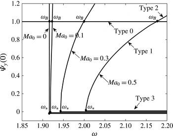
are shown in the various panels of figure 2; see the discussion in § 3. The resulting bifurcation diagrams of
 ${\it\Psi}_{y}(0)$
for each type of solution as a function of the swirl ratio
 ${\it\omega}$
at various Mach numbers,
 $Ma_{0}=0$
,
 $0.1$
,
 $0.3$
and
 $0.5$
, are shown in figure 3. The type 0 branch of solutions is characterized by
 ${\it\Psi}_{y}(0)=1$
for all
 ${\it\omega}$
and
 $Ma_{0}$
. At
 $Ma_{0}=0$
, the solutions exhibit a jump (vertical) bifurcation of type 1 solutions (with
 $0<{\it\Psi}_{y}(0)<1$
) from the type 0 branch of solutions at the special swirl ratio
 ${\it\omega}={\it\omega}_{B}=1.91586$
. Moreover, there is a jump bifurcation of type 2 solutions (with
 $1<{\it\Psi}_{y}(0)<3.485$
) at
 ${\it\omega}_{B}$
. Type 3 solutions with
 ${\it\Psi}_{y}(0)=0$
start at
 ${\it\omega}_{\ast }={\it\omega}_{B}$
and develop as
 ${\it\omega}$
increases above
 ${\it\omega}_{\ast }$
with an increasing size of
 $y_{0}$
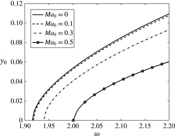
; see figure 4.
The bifurcation diagram of the centreline axial velocity
 ${\it\Psi}_{y}(0)$
versus the swirl ratio
 ${\it\omega}$
for solutions of the columnar flow (ODE) problem for a base solid-body rotation flow with a uniform axial velocity and a constant temperature at Mach numbers of
 $Ma_{0}=0,0.1,0.3$
and 0.5.

The size of the stagnation zone
 $y_{0}$
versus the swirl ratio
 ${\it\omega}$
for the type 3 breakdown solutions of the columnar flow (ODE) problem for a base solid-body rotation flow with a uniform axial velocity and a constant temperature at various Mach numbers.

As the axial flow Mach number,
 $Ma_{0}$
, is increased from zero, we find a transcritical bifurcation of type 1 and 2 solutions from the base type 0 branch of solutions at
 ${\it\omega}={\it\omega}_{B}(Ma_{0})$
. The swirl level
 ${\it\omega}_{B}$
increases monotonically with the increase of
 $Ma_{0}$
. For each
 $0<Ma_{0}<1$
, we also find that the type 1 solutions describe a decelerated flow near the centreline where
 ${\it\Psi}_{y}(0)$
decreases from
 $1$
to 0 as
 ${\it\omega}$
decreases from
 ${\it\omega}_{B}(Ma_{0})$
. At
 ${\it\omega}={\it\omega}_{\ast }(Ma_{0})$
, the type 1 solutions reach a state with
 ${\it\Psi}_{y}(0)=0$
. It should be noted that
 ${\it\omega}_{\ast }$
increases monotonically with the increase of
 $Ma_{0}$
. A branch of type 3 solutions (with
 ${\it\Psi}_{y}(0)=0$
) starts at
 ${\it\omega}={\it\omega}_{\ast }$
and develops for
 ${\it\omega}>{\it\omega}_{\ast }$
. The size,
 $y_{0}$
, of the stagnation zone of the type 3 solutions as a function of
 ${\it\omega}$
is shown in figure 4 for
 $Ma_{0}=0,0.1,0.3$
and
 $0.5$
. For these Mach numbers,
 $y_{0}$
increases with
 ${\it\omega}$
. Moreover, for a fixed
 ${\it\omega}$
,
 $y_{0}$
decreases with the inlet axial flow Mach number. In addition, type 2 solutions (with
 ${\it\Psi}_{y}(0)>1$
) exist for
 ${\it\omega}>{\it\omega}_{B}(Ma_{0})$
.
For each type of solution of the columnar ODE system,
 ${\it\Psi}(y)$
, we also computed the value of the columnar flow force,
 $E({\it\Psi})$
, and the values of
 ${\rm\Delta}E=E(0)-E({\it\Psi})$
. The resulting bifurcation diagrams of
 ${\rm\Delta}E$
as a function of
 ${\it\omega}$
for
 $Ma_{0}=0.3$
and
 $0.5$
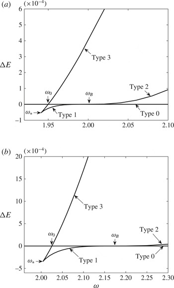
are shown in figure 5. For the type 0 solutions,
 ${\rm\Delta}E=0$
by definition. It can be seen that, for each Mach number,
 ${\rm\Delta}E$
of the type 1 solutions equals
 ${\rm\Delta}E$
of the type 3 solutions at
 ${\it\omega}={\it\omega}_{\ast }(Ma_{0})$
. The
 ${\rm\Delta}E$
values of type 1 solutions are negative for the range of swirl
 ${\it\omega}_{\ast }(Ma_{0})<{\it\omega}<{\it\omega}_{B}(Ma_{0})$
and become positive for the type 2 solutions when
 ${\it\omega}>{\it\omega}_{B}(Ma_{0})$
. However, the
 ${\rm\Delta}E$
values of the type 3 solutions increase from negative to positive and vanish at
 ${\it\omega}={\it\omega}_{0}(Ma_{0})$
, which is less than
 ${\it\omega}_{B}(Ma_{0})$
. The
 ${\rm\Delta}E$
values of the type 3 solutions are positive when
 ${\it\omega}>{\it\omega}_{0}(Ma_{0})$
. It should be noted that
 ${\it\omega}_{0}$
increases with the increase of Mach number,
 $Ma_{0}$
.
The bifurcation diagrams of the difference of columnar flow force
 ${\rm\Delta}E$
versus the swirl ratio
 ${\it\omega}$
for solutions of the columnar flow (ODE) problem for a base solid-body rotation with a uniform axial velocity and a constant temperature at (a)
 $Ma_{0}=0.3$
and (b)
 $Ma_{0}=0.5$
.

The results of solutions of the ODE problem shed light on the steady-state flows in the finite-length pipe. They show that the columnar solutions of type 0 are the outlet states of the parallel columnar flow solutions (2.18) in the pipe for all
 ${\it\omega}$
(the type 0 solutions of the PDE (2.13) with (2.14) and (2.15)). On the other hand, the columnar type 1 solutions are not outlet states of solutions of the problem in the range
 ${\it\omega}_{\ast }(Ma_{0})<{\it\omega}<{\it\omega}_{B}(Ma_{0})$
, while the columnar type 3 solutions are the outlet states of solutions of the problem that describe breakdown states in the pipe when
 ${\it\omega}\geqslant {\it\omega}_{0}(Ma_{0})$
(denoted by type 3 solutions of the PDE (2.13) with (2.14) and (2.15)).
In order to construct the bifurcation diagram of steady states in the pipe according to the PDE (2.13) with (2.14) and (2.15), we also need to account for the effect of pipe length on the various solutions bifurcating at
 ${\it\omega}_{1}(Ma_{0})$
, as found in Wang & Rusak (Reference Wang and Rusak1997a
) and Rusak et al. (Reference Rusak, Choi and Lee2007). Rusak et al. (Reference Rusak, Choi and Lee2007) showed a transcritical bifurcation of solutions of this problem from the branch of type 0 states in the pipe at
 ${\it\omega}={\it\omega}_{1}(Ma_{0})$
, which is greater than
 ${\it\omega}_{B}(Ma_{0})$
. The difference between
 ${\it\omega}_{1}(Ma_{0})$
and
 ${\it\omega}_{B}(Ma_{0})$
is inversely proportional to the square of the non-dimensional pipe length,
 $1/x_{0}^{2}$
. As the pipe length increases,
 ${\it\omega}_{1}(Ma_{0})$
approaches
 ${\it\omega}_{B}(Ma_{0})$
. For the type 0 states in the pipe the outlet centreline axial velocity is
 ${\it\Psi}_{y}(0,x_{0})=1$
. The bifurcating solutions at
 ${\it\omega}_{1}(Ma_{0})$
were also described analytically in Rusak et al. (Reference Rusak, Choi and Lee2007). They form type 1 and 2 states of the PDE (2.13) with (2.14) and (2.15) as
 ${\it\omega}$
changes around
 ${\it\omega}_{1}(Ma_{0})$
. These states describe type 1 flows in the pipe with deceleration and temperature increase near the centreline, and with a decreasing value of
 ${\it\Psi}_{y}(0,x_{0})$
as
 ${\it\omega}$
is decreased from
 ${\it\omega}_{1}(Ma_{0})$
. For
 ${\it\omega}>{\it\omega}_{1}(Ma_{0})$
, they describe type 2 flows in the pipe with acceleration and temperature decrease along the centreline. The outlet centreline axial velocity
 ${\it\Psi}_{y}(0,x_{0})$
of these states increases from 1 with the increase of
 ${\it\omega}$
above
 ${\it\omega}_{1}(Ma_{0})$
. As
 ${\it\omega}$
is decreased from
 ${\it\omega}_{1}(Ma_{0})$
, the type 1 states exhibit a zero value of
 ${\it\Psi}_{y}(0,x_{0})$
at
 ${\it\omega}={\it\omega}_{+}(Ma_{0})$
. Following the global analysis of incompressible swirling flows of Wang & Rusak (Reference Wang and Rusak1997a
), it is expected that the structure of the bifurcation is continuous when the Mach number is increased from zero to a higher value. Therefore, the type 1 states are connected at
 ${\it\omega}_{+}(Ma_{0})$
to type 3 states in the pipe for which
 ${\it\Psi}_{y}(0,x_{0})=0$
. As
 ${\it\omega}$
is further decreased from
 ${\it\omega}_{+}(Ma_{0})$
to
 ${\it\omega}_{0}(Ma_{0})+{\it\epsilon}(x_{0})$
, the branch of type 3 states appears. Here,
 ${\it\epsilon}(x_{0})>0$
is the effect of pipe length on
 ${\it\omega}_{0}$
and it decreases to zero as
 $x_{0}$
is increased. Our numerical simulations show that the correction is small when
 $x_{0}>6$
, but
 ${\it\epsilon}(x_{0})$
is not small when
 $x_{0}<6$
. The type 3 branch of states folds at
 ${\it\omega}={\it\omega}_{0}(Ma_{0})+{\it\epsilon}(x_{0})$
, and as
 ${\it\omega}$
is increased above
 ${\it\omega}_{0}(Ma_{0})+{\it\epsilon}(x_{0})$
, it forms the branch of breakdown states in the pipe. For the type 3 breakdown states in the pipe,
 ${\it\Psi}_{y}(0,x_{0})=0$
and the breakdown zone size at the outlet is given by
 $y_{0}$
as a function of
 $Ma_{0}$
(see figure 4).
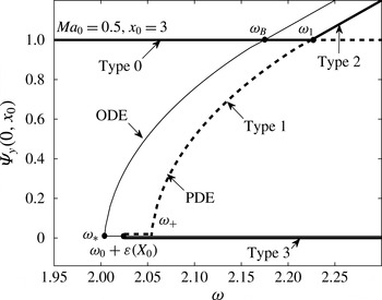
The bifurcation diagram of steady-state flows in a finite-length straight circular pipe according to the PDE (2.13) with (2.14) and (2.15) is shown in figure 6 for a representative case where
 $Ma_{0}=0.5$
and
 $x_{0}=3$
. The horizontal axis is the swirl ratio,
 ${\it\omega}$
, of the inlet flow. The vertical axis represents the outlet centreline axial velocity at the pipe outlet centreline,
 ${\it\Psi}_{y}(0,x_{0})$
. This is a representative parameter of the various types of steady swirling flows in the pipe. For the type 0 columnar state in the pipe,
 ${\it\Psi}_{y}(0,x_{0})=1$
for all
 ${\it\omega}$
. The type 1 and 2 states bifurcate at
 ${\it\omega}={\it\omega}_{1}(Ma_{0})$
. The type 1 states are represented by the dashed line in figure 6 and the type 2 states are represented by the solid line. Both types are described by the solutions in Rusak et al. (Reference Rusak, Choi and Lee2007). The type 3 states that connect
 ${\it\omega}_{+}(Ma_{0})$
and
 ${\it\omega}_{0}(Ma_{0})+{\it\epsilon}(x_{0})$
are also represented by the dashed line with
 ${\it\Psi}_{y}(0,x_{0})=0$
. The type 3 states in the range
 ${\it\omega}>{\it\omega}_{0}(Ma_{0})+{\it\epsilon}(x_{0})$
are described by the solid line with
 ${\it\Psi}_{y}(0,x_{0})=0$
. Also shown for reference are solutions of the columnar ODE problem (5.3) with (5.4). The swirling flow states in the finite-length pipe are related to the solutions of columnar ODEs only for the type 0 columnar and type 3 breakdown states. For each
 $Ma_{0}$
, we find that the columnar state is a unique steady state of the PDE problem when
 ${\it\omega}<{\it\omega}_{0}(Ma_{0})+{\it\epsilon}(x_{0})$
. There exist three steady states, type 0, type 1 and type 3, when
 ${\it\omega}_{0}(Ma_{0})+{\it\epsilon}(x_{0})\leqslant {\it\omega}\leqslant {\it\omega}_{1}(Ma_{0})$
and three steady states, type 0, type 2 and type 3, when
 ${\it\omega}>{\it\omega}_{1}(Ma_{0})$
.
The bifurcation diagram of the outlet centreline axial velocity
 ${\it\Psi}_{y}(0,x_{0})$
versus the swirl ratio
 ${\it\omega}$
for solutions of the axisymmetric flow problem (2.13) with (2.14) and (2.15) for a swirling flow in a finite-length straight circular pipe of non-dimensional length
 $x_{0}=3$
with an incoming solid-body rotation flow with a uniform axial velocity and a constant temperature at
 $Ma_{0}=0.5$
. The solid line represents stable solutions while the dashed line represents unstable solutions. The thin line describes for reference the ODE bifurcation diagram at
 $Ma_{0}=0.5$
.

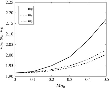
Figure 7 summarizes the variation of the important swirl levels,
 ${\it\omega}_{\ast }$
,
 ${\it\omega}_{0}$
and
 ${\it\omega}_{B}$
, with the Mach number,
 $Ma_{0}$
. These swirl ratios increase monotonically with increase of the Mach number. It can be seen that
 ${\it\omega}_{B}$
increases faster than
 ${\it\omega}_{0}$
(and
 ${\it\omega}_{\ast }$
) as the Mach number increases. Figure 7 together with figure 4 show that the appearance of vortex breakdown in a pipe is delayed with increase of Mach number. For a fixed
 ${\it\omega}$
, the breakdown zone is smaller when
 $Ma_{0}$
increases.
The swirl ratios
 ${\it\omega}_{\ast }$
,
 ${\it\omega}_{0}$
and
 ${\it\omega}_{1}$
as a function of the Mach number for a swirling flow in a finite-length straight circular pipe of non-dimensional length
 $x_{0}=3$
with an incoming solid-body rotation flow with a uniform axial velocity and a constant temperature.

5.2. Lamb–Oseen vortex model
Let the inlet flow describe a Lamb–Oseen vortex with a uniform axial speed (axial plug flow) and a uniform temperature, i.e.
 $$\begin{eqnarray}v_{0}(y)=\frac{1}{\sqrt{2y}}(1-\exp (-2by)),\quad w_{0}(y)=T_{0}(y)=1\quad \text{for }0\leqslant y\leqslant 1/2.\end{eqnarray}$$
Here,
 $b$
is the vortex core size parameter, where the vortex core radius is
 $r_{c}=1.12/\sqrt{b}$
. Then, the base pressure profile is given by
 $$\begin{eqnarray}p_{0y}={\it\gamma}Ma_{0}^{2}{\it\omega}^{2}p_{0}\frac{v_{0}^{2}(y)}{2yT_{0}(y)}={\it\gamma}Ma_{0}^{2}{\it\omega}^{2}p_{0}\frac{(1-\exp (-2by))^{2}}{4y^{2}},\end{eqnarray}$$
with a centreline condition,
 $p_{0}(0)=1$
. The function
 $p_{0}(y)$
is computed by a fourth-order accurate Runge–Kutta integration scheme. Since
 $T_{0}(y)=1$
,
 ${\it\rho}_{0}(y)=p_{0}(y)$
, and we have
 ${\it\Psi}_{y}=p_{0}(y)$
. Then,
 ${\it\Psi}(y)=\int _{0}^{y}p_{0}(\bar{y})\,\text{d}\bar{y}$
, which again can be computed by the fourth-order accurate Runge–Kutta integration scheme. To invert
 ${\it\Psi}(y)$
to
 $y({\it\Psi})$
, we approximate
 $$\begin{eqnarray}y({\it\Psi})=\mathop{\sum }_{n=1}^{n=N}a_{n}{\it\Psi}^{n},\end{eqnarray}$$
where typically
 $N=25$
, and the coefficients
 $a_{n}$
are found from a curve-fitting procedure to the numerical solution of
 ${\it\Psi}$
versus
 $y$
. It should be noted that the approximation (5.9) must satisfy
 $$\begin{eqnarray}y(0)=0,\quad y\left({\it\Psi}_{0}=\int _{0}^{1/2}{\it\rho}_{0}(\bar{y})\right)=1/2.\end{eqnarray}$$
Using (5.9), we can compute
 $$\begin{eqnarray}\displaystyle \left.\begin{array}{@{}c@{}}\displaystyle K({\it\Psi})={\it\omega}(1-\exp (-2by({\it\Psi}))),\\ \displaystyle K^{\prime }({\it\Psi})=\frac{2b{\it\omega}\exp (-2by({\it\Psi}))}{p_{0}(y({\it\Psi}))},\\ \displaystyle H^{\prime }({\it\Psi})=\frac{({\it\gamma}-1)Ma_{0}^{2}{\it\omega}^{2}v_{0}(y({\it\Psi}))v_{0y}(y({\it\Psi}))}{p_{0}(y({\it\Psi}))},\\ \displaystyle s^{\prime }({\it\Psi})=-\frac{{\it\gamma}({\it\gamma}-1)Ma_{0}^{2}{\it\omega}^{2}(1-\exp (-2by({\it\Psi})))^{2}}{4y^{2}p_{0}(y({\it\Psi}))}.\end{array}\!\!\right\} & & \displaystyle\end{eqnarray}$$
These are used to solve the system of ODEs (3.17) with
 $T$
and
 ${\it\rho}$
according to (3.15) and (3.16) and with boundary conditions (3.18).
In all computed examples for the Lamb–Oseen vortex, we focus on a representative case where
 $b=4$
(
 $r_{c}=0.56$
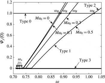
). The results are similar to those found for the solid-body rotation flow in § 5.1. The bifurcation diagrams of
 ${\it\Psi}_{y}(0)$
for the solutions of the columnar ODE problem as a function of the swirl ratio,
 ${\it\omega}$
, at various Mach numbers,
 $Ma_{0}=0$
,
 $0.1$
,
 $0.3$
and
 $0.5$
, are shown in figure 8. Unlike the solid-body rotation case, at
 $Ma_{0}=0$
, the solutions exhibit a transcritical bifurcation of type 1 and type 2 solutions from the type 0 branch of solutions at the special swirl ratio
 ${\it\omega}={\it\omega}_{B}=0.8825$
. Moreover, unlike the solid-body rotation case, type 3 solutions with
 ${\it\Psi}_{y}(0)=0$
start at
 ${\it\omega}_{+}=0.7382$
and develop as
 ${\it\omega}$
decreases down to
 ${\it\omega}_{\ast }=0.709$
. At
 ${\it\omega}_{\ast }$
, the branch of type 3 solutions folds and the type 3 solutions develop for
 ${\it\omega}>{\it\omega}_{\ast }$
. As the axial flow Mach number,
 $Ma_{0}$
, is increased from zero, we find a similar behaviour of the bifurcation diagram, but with higher values of
 ${\it\omega}_{B}$
,
 ${\it\omega}_{+}$
and
 ${\it\omega}_{\ast }$
that increase with
 $Ma_{0}$
. The corresponding size,
 $y_{0}$
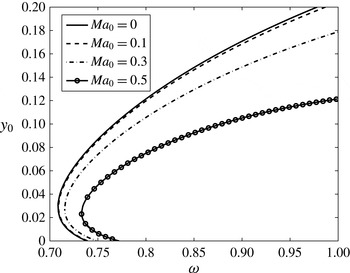
, of the stagnation zone of the type 3 solutions as a function of
 ${\it\omega}$
is shown in figure 9 for various values of
 $Ma_{0}$
. Unlike the solid-body rotation case, for these Mach numbers,
 $y_{0}$
first increases with
 ${\it\omega}$
decreasing from
 ${\it\omega}_{+}$
to
 ${\it\omega}_{\ast }$
and then folds as
 ${\it\omega}$
is increased from
 ${\it\omega}_{\ast }$
. There exist two type 3 solutions in the range of
 ${\it\omega}_{\ast }\leqslant {\it\omega}\leqslant {\it\omega}_{+}$
, one with a small stagnation zone and the other with a larger stagnation zone. Moreover, for a fixed
 ${\it\omega}$
greater than
 ${\it\omega}_{+}$
,
 $y_{0}$
decreases with increase of the inlet axial flow Mach number.
The bifurcation diagram of the centreline axial velocity
 ${\it\Psi}_{y}(0)$
versus the swirl ratio
 ${\it\omega}$
of solutions of the columnar flow (ODE) problem for a base Lamb–Oseen vortex with a uniform axial velocity and a constant temperature at Mach numbers
 $Ma_{0}=0,0.1,0.3$
and 0.5.

The size of the stagnation zone
 $y_{0}$
versus the swirl ratio
 ${\it\omega}$
for the type 3 breakdown solutions of the columnar flow (ODE) problem for a base Lamb–Oseen vortex with a uniform axial velocity and a constant temperature at various Mach numbers.

In addition, as in the solid-body rotation case, we find that the values of
 ${\rm\Delta}E$
of the type 1 solutions are negative in the range of
 ${\it\omega}_{\ast }\leqslant {\it\omega}\leqslant {\it\omega}_{B}$
, while the values of
 ${\rm\Delta}E$
of the type 2 solutions are positive in the range of
 ${\it\omega}>{\it\omega}_{B}$
. We also find from this analysis the values of
 ${\it\omega}_{0}$
as a function of
 $Ma_{0}$
for which breakdown states of the PDE problem appear for the first time as swirl is increased. In all cases,
 ${\it\omega}_{\ast }<{\it\omega}_{0}<{\it\omega}_{+}$
along the branch of type 3 solutions that fold back.
The results of solutions of the ODE problem for the Lamb–Oseen vortex show that for all
 ${\it\omega}$
the columnar solutions of type 0 are the outlet states of the type 0 parallel flow solutions in the pipe. The type 1 and connected type 3 solutions are not outlet states of solutions of the problem in the range
 ${\it\omega}_{\ast }(Ma_{0})<{\it\omega}<{\it\omega}_{B}(Ma_{0})$
. The columnar type 3 solutions are the outlet states of type 3 breakdown states in the pipe when
 ${\it\omega}\geqslant {\it\omega}_{0}(Ma_{0})$
.
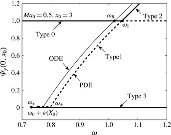
The bifurcation diagram of solutions of steady-state flows in a finite-length straight circular pipe according to the PDE problem is shown in figure 10 for a representative case where
 $b=4$
,
 $Ma_{0}=0.5$
and
 $x_{0}=3$
. The type 0 columnar states in the pipe are represented by
 ${\it\Psi}_{y}(0,x_{0})=1$
for all
 ${\it\omega}$
. The type 1 states are represented by the dashed line in figure 10 and the type 2 states are represented by the solid line. Both are described by the solutions of Rusak et al. (Reference Rusak, Choi and Lee2007). The type 3 breakdown solutions of the PDE problem are characterized by
 ${\it\Psi}_{y}(0,x_{0})=0$
for
 ${\it\omega}>{\it\omega}_{0}(Ma_{0})+{\it\epsilon}(x_{0})$
. Also shown for reference are solutions of the columnar ODE problem. The solutions of the swirling flow problem in the finite-length pipe are related with the solutions of columnar ODEs only for the type 0, 2 and 3 breakdown states.
The bifurcation diagram of the outlet centreline axial velocity
 ${\it\Psi}_{y}(0,x_{0})$
versus the swirl ratio
 ${\it\omega}$
for solutions of the axisymmetric flow problem (2.13) with (2.14) and (2.15) of a swirling flow in a finite-length straight circular pipe of non-dimensional length
 $x_{0}=3$
with an incoming Lamb–Oseen vortex with a uniform axial velocity and a constant temperature at
 $Ma_{0}=0.5$
. The solid line represents stable solutions while the dashed line represents unstable solutions. The thin line describes for reference the ODE bifurcation diagram at
 $Ma_{0}=0.5$
.

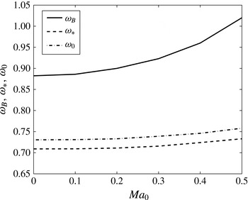
The monotonic increase of the swirl levels,
 ${\it\omega}_{\ast }$
,
 ${\it\omega}_{0}$
and
 ${\it\omega}_{B}$
, as a function of the Mach number,
 $Ma_{0}$
, for the Lamb–Oseen vortex with
 $b=4$
is presented in figure 11. We find that
 ${\it\omega}_{0}$
(and
 ${\it\omega}_{\ast }$
) slowly increases with the Mach number while
 ${\it\omega}_{B}$
increases faster. Figures 9 and 11 show for the Lamb–Oseen vortex that the appearance of vortex breakdown in a finite-length pipe is delayed by the compressibility effect.
The swirl ratios
 ${\it\omega}_{\ast }$
,
 ${\it\omega}_{0}$
and
 ${\it\omega}_{1}$
as a function of the Mach number for a swirling flow in a finite-length straight circular pipe of non-dimensional length
 $x_{0}=3$
with an incoming Lamb–Oseen vortex with a uniform axial velocity and a constant temperature.

6. Conclusions
A global analysis of steady states of inviscid compressible subsonic swirling flows in a finite-length straight circular pipe can be developed. The basic model considers a swirling flow that is generated by a fixed-in-time and fixed-in-space vortex generator ahead of the pipe and a passive discharge device at the outlet. The model reflects the imbalance between the inlet and outlet conditions in a finite-length pipe. The analysis is based on a nonlinear partial differential equation for the solution of the flow stream function in terms of the inlet flow specific total enthalpy, specific entropy and circulation functions. This equation generalizes the classical Squire–Long equation to the study of compressible swirling flows and reflects the thermo–physical interactions in the flows. Several types of solutions of the resulting nonlinear ordinary differential equation for the columnar case are found (see figure 2): the base flow, the decelerated flow along the centreline, the accelerated flow along the centreline and flows with a centreline finite-size stagnation zone. A flow force condition, (4.8), is also derived and is used to determine which of the columnar solutions is the outlet state of the flow in the pipe. These solutions together with the results of Rusak et al. (Reference Rusak, Choi and Lee2007) are used to form the bifurcation diagram of steady compressible flows with swirl as the inlet swirl level is increased at a fixed inlet Mach number.
The present approach is applied to two profiles of inlet flows, solid-body rotation and the Lamb–Oseen vortex, both with a uniform axial velocity and temperature. Figures 6 and 10 summarize the results for each of the inlet flow profiles respectively, suggesting that the results are robust for a variety of inlet swirling flows. Figures 7 and 11 provide for each inlet flow profile theoretical predictions of the critical swirl levels,
 ${\it\omega}_{0}$
and
 ${\it\omega}_{B}$
, for the appearance of vortex breakdown states as a function of the inlet Mach number. The analysis shows in both cases the delay in the appearance of breakdown with increase of the inlet axial flow Mach number in the subsonic range of operation.
The results of Rusak et al. (Reference Rusak, Choi and Lee2007) help to clarify the linear and nonlinear stability characteristics of the various flow states in the pipe for both the solid-body rotation and the Lamb–Oseen vortex. The type 0 columnar states are asymptotically stable when
 $0<{\it\omega}<{\it\omega}_{1}(Ma_{0})$
. The columnar states become unstable when
 ${\it\omega}>{\it\omega}_{1}(Ma_{0})$
and perturbations on these states must grow in time and develop the breakdown process. The type 1 and the connected type 3 states in the range of
 ${\it\omega}_{0}(Ma_{0})+{\it\epsilon}(x_{0})<{\it\omega}<{\it\omega}_{1}(Ma_{0})$
are unstable while the type 2 states are asymptotically stable when
 ${\it\omega}>{\it\omega}_{1}(Ma_{0})$
. Following the numerical simulations of incompressible swirling flows in a pipe by Rusak et al. (Reference Rusak, Wang, Xu and Taylor2012) and Rusak & Wang (Reference Rusak and Wang2014), the type 2 accelerated flow states in the pipe with
 ${\it\omega}>{\it\omega}_{1}(Ma_{0})$
and the type 3 breakdown states in the pipe with
 ${\it\omega}>{\it\omega}_{0}(Ma_{0})+{\it\epsilon}(x_{0})$
form attractors of the flow dynamics. When
 $0<{\it\omega}<{\it\omega}_{0}(Ma_{0})+{\it\epsilon}(x_{0})$
, any initial perturbation decays in time and the flow returns to a columnar state. When
 ${\it\omega}_{0}(Ma_{0})+{\it\epsilon}(x_{0})<{\it\omega}<{\it\omega}_{1}(Ma_{0})$
, sufficiently small initial perturbations decay in time and the flow returns to a columnar state, while larger perturbations evolve to the type 3 breakdown states. When
 ${\it\omega}>{\it\omega}_{1}(Ma_{0})$
, the initial perturbations evolve to either the type 2 accelerated flow state or the type 3 breakdown state that corresponds to a given
 ${\it\omega}$
, depending on the domain of attraction of these states. The domain of attraction of the breakdown states increases while that of the accelerated flow states decreases as
 ${\it\omega}$
increases above
 ${\it\omega}_{1}(Ma_{0})$
. Therefore, it is expected that the flow typically evolves to the breakdown states when
 ${\it\omega}>{\it\omega}_{1}(Ma_{0})$
.
The present results match with the trend of Mach number effect on vortex breakdown found in the experiment of Visbal & Gordnier (Reference Visbal and Gordnier1995) and in the numerical simulations of Kuruvila & Salas (Reference Kuruvila and Salas1990), Melville (Reference Melville1996) and Herrada et al. (Reference Herrada, Prez-Sabroid and Barrero2003). The results are also supported by the detailed discussion in § 5 of Rusak & Lee (Reference Rusak and Lee2002), where the transport equation for the azimuthal vorticity was analysed and the effects of vorticity stretching by the circulation gradient and of baroclinic terms on the azimuthal vorticity convection were explored. It was found that the baroclinic effects resulting from the interaction between the temperature gradient and the circulation function are responsible for the increase of the critical swirl,
 ${\it\omega}_{1}$
, as the inlet flow Mach number is increased. A similar effect of baroclinic terms on the threshold swirl level for vortex breakdown,
 ${\it\omega}_{0}$
, also exists.