1. Introduction
The dynamics of magnetised plasmas and beams confined by an axial magnetic field and put in rotation through a radial electric field has been extensively investigated, both from a basic plasma physics standpoint and to enable applications. Rotating plasmas have for instance been investigated –and continue to be – for the purpose of magnetic confinement fusion (Wilcox Reference Wilcox1959), including in homopolar configurations (Anderson et al. Reference Anderson, Baker, Bratenahl, Furth, Ise, Kunkel and Stone1958), rotating mirrors (Lehnert Reference Lehnert1971; Bekhtenev et al. Reference Bekhtenev, Volosov, Pal'chikov, Pekker and Yudin1980; Ellis et al. Reference Ellis, Case, Elton, Ghosh, Griem, Hassam, Lunsford, Messer and Teodorescu2005; Fetterman & Fisch Reference Fetterman and Fisch2008, Reference Fetterman and Fisch2010) and rotating tokamaks (Stix Reference Stix1971; Ochs & Fisch Reference Ochs and Fisch2017; Rax, Gueroult & Fisch Reference Rax, Gueroult and Fisch2017). Rotating plasmas have also been the object of continued attention for mass separation applications (Dolgolenko & Muromkin Reference Dolgolenko and Muromkin2009, Reference Dolgolenko and Muromkin2017; Zweben, Gueroult & Fisch Reference Zweben, Gueroult and Fisch2018), notably in the form of plasma centrifuges (Bonnevier Reference Bonnevier1966; Krishnan, Geva & Hirshfield Reference Krishnan, Geva and Hirshfield1981; Prasad & Krishnan Reference Prasad and Krishnan1987), crossed-field rotating plasmas (Ohkawa & Miller Reference Ohkawa and Miller2002; Shinohara & Horii Reference Shinohara and Horii2007; Gueroult et al. Reference Gueroult, Zweben, Fisch and Rax2019b; Liziakin et al. Reference Liziakin, Antonov, Usmanov, Melnikov, Timirkhanov, Vorona, Smirnov, Oiler, Kislenko and Gavrikov2021) and rotating magnetic field configurations (Rax & Gueroult Reference Rax and Gueroult2016). In parallel to these applications driven studies, the complementary problem of angular momentum coupling between electromagnetic waves and particles has been examined in the study of particle acceleration (Rax & Robiche Reference Rax and Robiche2010; Thaury et al. Reference Thaury, Guillaume, Corde, Lehe, Le Bouteiller, Ta Phuoc, Davoine, Rax, Rousse and Malka2013), magnetic field generation in plasma channels and plasma bubbles (Kostyukov et al. Reference Kostyukov, Shvets, Fisch and Rax2002; Shvets, Fisch & Rax Reference Shvets, Fisch and Rax2002) and isotope separation (Rax, Robiche & Fisch Reference Rax, Robiche and Fisch2007).
A basic question of importance to these studies, but also to shed light on the intricate effects of rotation in astrophysics (Balbus & Hawley Reference Balbus and Hawley1998; Benomar et al. Reference Benomar, Bazot, Nielsen, Gizon, Sekii, Takata, Hotta, Hanasoge, Sreenivasan and Christensen-Dalsgaard2018), is how to diagnose plasma rotation. Asking this question is fundamentally asking for physical probes sensitive to fluid vorticity. Interestingly, it has recently been shown that rotation could imprint its signature on the polarisation of a wave propagating through a rotating plasma (Gueroult et al. Reference Gueroult, Shi, Rax and Fisch2019a), offering in turn unique opportunities to infer the rotation direction in pulsars. A challenge here, however, is that in a magnetised plasma both this polarisation drag effect (Jones Reference Jones1976; Player Reference Player1976) (also referred to as the mechanical Faraday effect) and the classic Faraday rotation (Faraday Reference Faraday1846; Stix Reference Stix1992) are at play (Gueroult, Rax & Fisch Reference Gueroult, Rax and Fisch2020). Measuring plasma rotation through polarisation drag hence requires disambiguating this effect from Faraday rotation. Similarly, harnessing polarisation drag in laboratory experiments likely requires conditions such that polarisation drag dominates over Faraday rotation (Gueroult et al. Reference Gueroult, Rax and Fisch2020). Polarisation, however, corresponds only to the spin component of the wave angular momentum. Indeed, waves can also carry orbital angular momentum (OAM) through helical phase fronts of the type $\exp j( l\theta -\beta z)$ with $l\in \Bbb {Z}$
 and $\beta \in \Bbb {R}$
 , and where $\theta$
 and $z$
 are the transverse azimuthal angle and the propagation axis in a cylindrical coordinate system (Gough Reference Gough1986; Allen et al. Reference Allen, Beijersbergen, Spreeuw and Woerdman1992; Barnett & Allen Reference Barnett and Allen1994; van Enk & Nienhuis Reference van Enk and Nienhuis1994; Stenzel Reference Stenzel2016; Barnett, Babiker & Padgett Reference Barnett, Babiker and Padgett2017).
In isotropic media, mechanical rotation has been postulated (Padgett et al. Reference Padgett, Whyte, Girkin, Wright, Allen, Öhberg and Barnett2006; Götte, Barnett & Padgett Reference Götte, Barnett and Padgett2007; Leach et al. Reference Leach, Wright, Götte, Girkin, Allen, Franke-Arnold, Barnett and Padgett2008) and then demonstrated experimentally (Franke-Arnold et al. Reference Franke-Arnold, Gibson, Boyd and Padgett2011) to lead to image rotation. This phenomenon, analogously to the polarisation rotation that stems from a phase shift between right- and left-circularly polarised modes, results from a mechanically induced phase shift between the positive and negative OAM-carrying modes (Wisniewski-Barker et al. Reference Wisniewski-Barker, Gibson, Franke-Arnold, Boyd and Padgett2014). Image rotation has hence been coined as the mechanical Faraday effect for OAM-carrying beams. Yet, owing to its similarities with Fresnel drag for a uniform motion (Fresnel Reference Fresnel1818), image rotation is equally referred to as rotatory photon drag (Franke-Arnold et al. Reference Franke-Arnold, Gibson, Boyd and Padgett2011). Reflecting these two roots, we refer to it here as Faraday–Fresnel rotation (FFR).
An interesting property of FFR in a dielectric medium is that, in contrast to polarisation rotation, it is insensitive to a magnetic field aligned with the propagation direction. Measuring FFR could hence remove the challenges faced by polarisation drag to measure rotation in a rotating magnetised plasma, as suggested for ultracold atomic gases (Ruseckas et al. Reference Ruseckas, Juzeliũnas, Öhberg and Barnett2007). Yet, while both linear and angular Fresnel drag have been studied in isotropic, non-gyrotropic rotating media (Götte et al. Reference Götte, Barnett and Padgett2007; Leach et al. Reference Leach, Wright, Götte, Girkin, Allen, Franke-Arnold, Barnett and Padgett2008), the case of rotating gyrotropic media such as a rotating magnetised plasma has not yet been investigated. Conceptually, anisotropy and gyrotropy bring out additional complexity in that the polarisation state and the wavevector direction can be set independently for a given frequency in isotropic media, whereas these two parameters are no longer independent in anisotropic or gyrotropic media.
Two approaches can be used to examine the effect of rotation on waves carrying OAM in a rotating magnetised plasma. One possibility is to consider the transformation of the various parameters from the rotating plasma rest frame to the laboratory frame. This is the approach we previously used to uncover the effect of plasma rotation on the wave's spin angular momentum (Gueroult et al. Reference Gueroult, Shi, Rax and Fisch2019a, Reference Gueroult, Rax and Fisch2020). Another possibility is to carry out the calculations in the laboratory frame starting from first principles. This is the approach we will use in this work as it proves more straightforward and also provides more directly physical insights into this new plasma effect. The approach in this study is, therefore, to solve the particle dynamics to calculate the rotating plasma linear response. We specifically consider here the low frequency electronic branches where the coupling between the fields and the particles is strong, that is the Trivelpiece–Gould (TG) and whistler–helicon (WH) modes (Stix Reference Stix1992; Davidson Reference Davidson2001).
This paper is organised as follows. In the next section, § 2, we introduce the effect of rotation on plasma waves carrying OAM through an analogy with the effect of a magnetic field on the spin angular momentum (SAM) component of a wave (i.e. its polarisation), and briefly recall the characteristics of TG and WH plasma waves as they will be the focus of our work. Section 3 then summarises the properties of Brillouin rotation in a cold magnetised plasma column used later on as our rotating plasma equilibrium. With these tools in hand, the dispersion relation for TG and WH waves in a rotating plasma are derived and analysed in §§ 4 and 5, respectively. In both instances FFR and its parametric dependencies are identified, and antennae designs that could excite these rotating waves are proposed. Building on this finding, § 6 examines the effect on a wave packet containing a combination of counter-rotating OAM-carrying eigenmodes, and shows how rotation leads to the Faraday–Fresnel splitting (FFS) of this wave packet. Finally § 7 summarises the main findings of this study.
2. Phenomenology of Faraday–Fresnel rotation in a rotating plasma
Throughout this study we write $( r,\theta ,z)$ , a set of cylindrical coordinates on the cylindrical coordinate system $( \boldsymbol {e}_{r},\boldsymbol {e}_{\theta },\boldsymbol {e}_{z})$
 , and define $z$
 as the direction of both the background static magnetic field $\boldsymbol {B}_0 = B_0\boldsymbol {e}_{z}$
 and the plasma angular velocity $\boldsymbol {\varOmega }=\varOmega \boldsymbol {e}_{z}$
 .
2.1. Polarisation rotation from phase shift between circularly polarised eigenmodes
To draw an analogy between the classical Faraday effect and FFR, let us first recall the basic picture relating polarisation rotation to circularly polarised eigenmodes. For this, consider a plane wave with a phase factor $\exp j( \omega t-\beta z)$ propagating along the magnetic field in an homogeneous plasma at rest. The study of the cold plasma dispersion relation between the axial wavevector $\beta$
 and the frequency $\omega$
 leads to the identification of the two left- ($L$
 ) and right- ($R$
 ) circularly polarised modes such that

Here $\omega _{c\alpha } = |q_{\alpha }|B_0/m_{\alpha }$ , $\alpha =i,e$
 is the (positive) cyclotron frequency and $\omega _{L/R} = ({\omega _{pe}}^2+{\omega _{ce}}^2/4)^{1/2}\pm \omega _{ce}/2$
 are the left and right cutoff with $\omega _{pe} = ne^2/(m_e\epsilon _0)$
 the plasma frequency. At high frequency $\omega >\omega _{ce}$
 the electrons’ inertia response dominates the dispersion relation and (2.1) can be expanded to give the phase difference $\delta \varphi$
 between the $L$
 and $R$
 modes accumulated when propagating one wavelength $\lambda = (\lambda _R+\lambda _L)/2$
 along $z$
 :

The phase difference derived in (2.2) is the classical formula describing the high-frequency Faraday SAM rotation in a magnetised plasma at rest. A very similar result, though not with the same frequency scaling, can be obtained by considering the phase velocity difference between right- and left-circularly polarised wave as a result of the medium's rotation (Jones Reference Jones1976; Player Reference Player1976; Götte et al. Reference Götte, Barnett and Padgett2007; Gueroult et al. Reference Gueroult, Rax and Fisch2020; Steinitz & Averbukh Reference Steinitz and Averbukh2020; Milner et al. Reference Milner, Steinitz, Averbukh and Milner2021).
2.2. Faraday–Fresnel rotation from phase shift between OAM-carrying eigenmodes
Plasma waves carrying OAM (see Appendix A for a discussion of spin and OAM in waves and particles) have been the object of growing attention over the last decade. In unmagnetised plasmas, OAM-carrying plasma waves have been studied theoretically mostly under the scalar paraxial approximation (see, e.g. Mendonca, Ali & Thidé Reference Mendonca, Ali and Thidé2009; Mendonça Reference Mendonça2012a,Reference Mendonçab), although exact solutions of the vector Maxwell equations have recently been derived (Chen, Qin & Liu Reference Chen, Qin and Liu2017). Meanwhile, in cold magnetised plasmas, waves carrying OAM have been reported in the form of TG and WH waves (Stenzel & Urrutia Reference Stenzel and Urrutia2015a; Stenzel Reference Stenzel2016; Urrutia & Stenzel Reference Urrutia and Stenzel2016), as well as predicted for twisted shear Alfvén waves (Shukla Reference Shukla2012). Because our interest in this study is in Brillouin rotating plasmas, that is as it will be detailed in the next section in a plasma rotating as a result of an $\boldsymbol {E}\times \boldsymbol {B}$ configuration in cylindrical geometry, we focus our attention on magnetised plasmas and consider more specifically TG and WH modes.
Whistler–helicon waves are intermediate frequency $\omega _{lh}<\omega <\omega _{ce}$ waves propagating along the magnetic field, with $\omega _{lh}$
 the lower hybrid frequency. The plasma response in this regime is dominated by the electron Hall current, which allows simplification of the dispersion relation (2.1) to obtain the classical Whistler dispersion

On the other hand non-rotating TG are electrostatic modes that propagate near the electron cyclotron frequency $\omega _{ce}$ and the electron plasma frequency $\omega _{pe}$
 . These waves are characterised by an electric potential proportional to $J_{l}( \beta _{\bot }r) \exp j( \omega t-\beta _{TG}z)$
 where $J_{l}$
 is the ordinary Bessel function of order $l\in \Bbb {Z}$
 , and the dispersion relation in this case is (Trivelpiece & Gould Reference Trivelpiece and Gould1959)

with $\omega _{uh}\sim ({\omega _{pe}}^2+{\omega _{ce}}^2)^{1/2}$ the upper hybrid frequency.
As mentioned above, both TG waves (Urrutia & Stenzel Reference Urrutia and Stenzel2016) and WH waves (Stenzel & Urrutia Reference Stenzel and Urrutia2015a) with helical phase front of the form $\exp j(\omega t\pm l\theta -\beta _{\pm l}z)$ can propagate in a cold magnetised plasma at rest (Stenzel Reference Stenzel2016). Both positive and negative azimuthal mode numbers $l$
 , that is to say both positive and negative orbital helicities for the same absolute value of OAM content, can propagate and be generated through an appropriate phasing of the generating antenna array. It is important to underline here though that the wave rotation should not be construed as the rotation of the field vectors (i.e. the waves polarisation), and only indicates a rotation of the transverse wave pattern. Whistler modes are for instance right-circularly polarised modes. The superposition of azimuthal modes of equal amplitudes but opposite azimuthal mode number (OAM of $\pm l\hbar$
 ) then leads to an azimuthally standing wave (zero OAM), very much like the superposition of right- and left-circularly polarised modes (SAM of $\pm \hbar$
 ) leads to a linearly polarised wave (zero SAM).
By analogy with the phase shift between opposite SAM eigenmodes (left- and right-circularly polarised modes) given in (2.2), we can define the phase shift between opposite OAM-carrying eigenmodes

with $\beta _{\pm l}$ the longitudinal wavevector of the wave with azimuthal mode number $\pm l$
 . As we will show, this OAM phase difference is zero absent rotation (i.e. for $\varOmega =0$
 ) for both WH and TG modes. This is because in this case $\beta _{+l} = \beta _{-}$
 , so that the transverse wave pattern produced by the superposition of opposite OAM-carrying eigenmodes does not depend on $z$
 . This is analogue to the constant linear polarisation observed if the phase velocity of right- and left-circularly polarised modes is the same. Building on this analogy, we will show that plasma rotation $\varOmega \neq 0$
 leads to $\beta _{+l} \neq \beta _{-}$
 , and therefore now to a rotation of the transverse wave pattern along $z$
 , which we refer to as FFR. The dispersive form factor $F$
 introduced in (2.5) and derived in (4.18) and (5.26) for TG and WH waves, respectively, quantifies the strength of this effect.
Finally, note that this study is limited to the analysis of the OAM dynamics through the reactive (or adiabatic) part of the plasma response. The active (or resonant) part of the plasma response, which leads to SAM and OAM transfer, is assumed negligible as we consider a cold collisionless plasma model. This active or resonant part of the interaction is only briefly discussed in Appendix A to provide a fuller picture of the SAM and OAM dynamics.
3. Brillouin rotation of a magnetised plasma column
Before embarking on the derivation of FFR for the TG and WH modes, the properties of the Brillouin rotating plasmas considered in the rest of this manuscript are briefly recalled here.
Brillouin rotation refers to the rotation of a magnetised plasma column which results from the combination of an axial confining magnetic field $\boldsymbol {B}_{0}=B_{0}\boldsymbol {e}_{z}$ and a radial electric field $\boldsymbol {E}_{0}=B_{0}\varOmega r\boldsymbol {e}_{r}$
 . As shown next, the plasma angular velocity $\varOmega =\textrm {d}\theta /\textrm {d} t$
 is then the $E\times B$
 drift rigid body rotation corrected by inertial effects (Brillouin Reference Brillouin1945), as well as possibly by collisional effects (Rax et al. Reference Rax, Fruchtman, Gueroult and Fisch2015, Reference Rax, Kolmes, Ochs, Fisch and Gueroult2019). In a non-neutral plasma the electric field $\boldsymbol {E}_{0}$
 is the space charge field (Davidson Reference Davidson2001). On the other hand, the electric field $\boldsymbol {E}_{0}$
 in a quasi-neutral plasma requires in steady-state maintaining a small uniform space charge $\varepsilon _{0}\boldsymbol {\nabla }\boldsymbol {\cdot } \boldsymbol {E}_{0} = 2\varepsilon _{0}\varOmega B_{0}$
 , and a DC or RF power input is thus needed to maintain this small deviation from quasi-neutrality against short circuiting radial currents (Kolmes et al. Reference Kolmes, Ochs, Mlodik, Rax, Gueroult and Fisch2019; Rax et al. Reference Rax, Kolmes, Ochs, Fisch and Gueroult2019).
Neglecting for simplicity collisions in this study and writing $\boldsymbol {v}_{0}$ for the particle fluid velocity, the steady-state momentum balance between inertia, electric and magnetic forces writes as

with $q$ the particle charge. The left-hand side describes inertia while the right-hand side accounts for electric and magnetic forces. Equation (3.1) has two solutions,

associated with the two roots $\varOmega _{\pm }$ of the characteristic equation

obtained by substituting (3.2) into (3.1) (Brillouin Reference Brillouin1945; Davidson Reference Davidson2001). Consistent with earlier notations, we use here $\omega _c = |q|B_0/m$ as the unsigned cyclotron frequency.
In the remainder of this study we consider only the small root associated with the slow $E\times B$ rotation, that is $\varOmega _{-}\approx -\varOmega$
 , as it is the rotation mode spontaneously observed in quasi-neutral plasmas experiments. It also leads to $\varOmega _{e}=\varOmega _{i}$
 , or in other words solid body rotation at equal angular frequency for ions and electrons. However, since both slow $\varOmega _{-}\approx -\varOmega$
 and fast $\varOmega _{+}\approx -q\omega _{c}/|q|$
 rotation modes have been observed and analysed in non-neutral plasmas (Davidson Reference Davidson2001), it is worth noting here that our findings could easily be extended and applied to higher angular velocities.
In the next two sections we will perturb this $[\boldsymbol {v}_{0},\boldsymbol {E}_{0},\boldsymbol {B}_{0}]$ Brillouin equilibrium given by (3.1) and (3.2) with helical electrostatic and electromagnetic waves $[\boldsymbol {E}( r,\theta ,z,t) ,\boldsymbol {B}( r,\theta ,z,t)]$
 with a space and time structure of the form

According to Appendix A, $\hat {L}_{z}\boldsymbol {A}=-l\boldsymbol {A}$ and $\hat {P}_{z}\boldsymbol {A}=-\beta \boldsymbol {A}$
 , so that one quantum of these waves carry an OAM $l\hbar$
 and a linear angular momentum $\beta \hbar$
 . We will then derive the expressions describing the rotating plasma response to this helical electromagnetic wave to obtain the dispersion relation. The dispersion relation will finally be used to identify FFR and FFS, that is to say the effect of plasma rotation on OAM-carrying waves. The following set of relations:


will be particularly useful to solve Maxwell's equation for the TG and WH modes.
4. Faraday–Fresnel rotation for TG waves
In a magnetised plasma column close to the plasma and cyclotron frequencies both cyclotron and Langmuir oscillations are expected to propagate along the magnetic field. The analysis of these electrostatic elementary excitations suggests considering a potential electric field $\boldsymbol {E}$ such that $\boldsymbol {\nabla }\times \boldsymbol {E}=\boldsymbol {0}$
 (Davidson Reference Davidson2001; Stenzel & Urrutia Reference Stenzel and Urrutia2016). This electric field derives from a potential $\phi$
 whose dynamics is associated with an oscillating electron space charge $-ne$
 . We therefore consider the propagation of potential and density perturbations


over the equilibrium static radial electric potential $\phi _0 = -B_{0}\varOmega r^{2}/2$ from which derives the electric field $\boldsymbol {E}_0$
 driving the equilibrium Brillouin rotation and uniform densities $n_0$
 . Equation (3.1) provides the unperturbed momentum balance for a Brillouin flow while the relation $\boldsymbol {\nabla }\boldsymbol {\cdot } n_{0}\boldsymbol {v}_{0}=0$
 yields the unperturbed charge conservation relation.
4.1. Dispersion relation
For a weak electronic perturbation of this Brillouin flow, the linearised momentum balance (4.3), and the linearised charge conservation relation (4.4),


yield a set of coupled equations relating $n$ to $\phi$
 . Making use of (3.9), (3.10) and (4.3) can be rearranged as

while (4.4) can be rewritten as

We then apply the three linear operators $\boldsymbol {\nabla }\times$ , $\boldsymbol {\nabla }\boldsymbol {\cdot }$
 and $\boldsymbol {e}_z\boldsymbol {\cdot }$
 to (4.5) to obtain three relations relating the divergence, the curl and the longitudinal component of the velocity $\boldsymbol {v}$
 . With the help of (3.6) and (3.8) this yields


where we have used the Poisson equation to eliminate $\Delta \phi$ in (4.8). Velocity-dependent terms $\boldsymbol {\nabla }\times \boldsymbol {v}$
 , $\boldsymbol {\nabla }\boldsymbol {\cdot }\boldsymbol {v}$
 and $\boldsymbol {v}$
 are then eliminated between (4.6), (4.7), (4.8) and (4.9) to write the oscillating space charge $-ne$
 as a function of the oscillating potential $\phi$
 :

Poisson equation $\Delta \phi = ne/\varepsilon _{0}$ for the perturbation potential $\phi ( r)$
 given in (4.1) finally leads to the final equation describing TG modes propagation,

where we have defined the parameter

Looking at (4.11) and (4.12), one first verifies that the classical TG relation (2.4) first derived by Trivelpiece & Gould (Reference Trivelpiece and Gould1959) is recovered in the limit of zero rotation $\varOmega =0$ . One additionally notes that $T_{+l}=T_{-l}$
 in this same limit of zero rotation, but that $T_{+l}\neq T_{-l}$
 for $\varOmega \neq 0$
 . Finally, a closer examination of (4.12) shows that the $\varOmega$
 -dependent terms $(\omega _{ce}-2\varOmega )$
 can be traced back to the Coriolis effect in the plasma rest frame (Lehnert Reference Lehnert1962; Uberoi & Das Reference Uberoi and Das1970), while the $(\omega -l\varOmega )$
 terms are to be attributed to the Doppler effect in the plasma rest frame.
4.2. Solutions as superpositions of eigenmodes with opposite OAM contents
A general non-singular solution of Poisson equation (4.11) describing TG modes with an OAM content such that $| L_{z}/P_{z}| =l/\beta$ consists of a linear combination of two counter-rotating Bessel modes

where $l\in \Bbb {N}$ is a positive number and the mode amplitudes $\phi _{\pm }$
 are assumed to be set by the antenna. Classically TG modes are studied as confined modes in a conducting cylindrical cavity of length $L$
 and radius $a$
 , which leads to the boundary conditions $E_{\theta }( a) = E_{z}( a) =0$
 , and from there to $J_{l}( \beta T_{l}a) =0$
 . The axial wave vector $\beta$
 is then determined through the usual requirement of a standing wave along $z$
 , that is $\beta L=p{\rm \pi}$
 with $p\in \Bbb {Z}$
 . This set of conditions fully determines the resonant mode frequency in the cylindrical cavity through $J_{l}( p{\rm \pi} T_{l}a/l) =0$
 .
Instead of following this approach, we look here for free TG modes propagating along $z$ . Specifically we consider free TG modes displaying the same radial structure $J_{l}( \alpha r)$
 . In other words, instead of the solution in (4.13) consisting of the superposition of modes with opposite azimuthal mode numbers $\pm l$
 , different radial structure and identical axial wavevectors $\beta$
 , we consider non-singular solutions

that are the superposition of modes with opposite azimuthal mode numbers $\pm l$ , identical radial structure, but different axial wavevectors $\beta _{+l}\neq \beta _{-l}$
 . Both the frequency $\omega$
 and the transverse parameter $\alpha$
 are set by the antenna, whereas the wave vectors $\beta _{+l}$
 and $\beta _{-l}$
 depend on the rotating plasma properties through the condition

which guarantees that $\phi$ verifies the radial Poisson equation (4.11). Following the analysis given in Appendix A, the longitudinal electric field associated with the $\pm l$
 modes in (4.14) are eigenvectors of $S_{z}$
 with $0$
 eigenvalue and of $L_{z}$
 with eigenvalues $\pm l$
 , and thus also of the sum $L_{z}+S_{z}$
 .
4.3. Faraday–Fresnel rotation
Going back to (2.5), the normalised difference between these wave vectors $\beta _{+l}$ and $\beta _{-l}$
 is

From (4.12), the lowest order in $\varOmega /\omega$ estimate for this phase shift then writes as

where we have defined the form factor

which is $O(1)$ at low frequency.
Equation (4.17) shows that, indeed, plasma rotation introduces a phase shift between OAM-carrying TG eigenmodes with opposite azimuthal mode numbers, or in other words to FFR. The wave transverse phase structure is hence rotated as the wave propagates along the rotation and magnetic axis $\boldsymbol {e}_z$ . Comparing now (4.17) with the phase shift introduced by rotation between circularly polarised eigenmodes (Gueroult et al. Reference Gueroult, Shi, Rax and Fisch2019a, Reference Gueroult, Rax and Fisch2020), that is to say to the SAM mechanical Faraday effect, one finds that the phase shifts are in both cases proportional to the ratio of plasma angular frequency to wave angular frequency $\varOmega /\omega$
 , but that in addition, (4.17) depends linearly on the azimuthal wavenumber $l$
 . This $\varOmega /\omega$
 scaling is also consistent with image rotation in an isotropic dielectric (Götte et al. Reference Götte, Barnett and Padgett2007).
4.4. Possible antenna design
To conclude this section we propose here a coupling structure designed to launch the mode (4.14), i.e. two TG modes with identical radial structure but opposite azimuthal mode numbers. For this we draw on the inductive antenna design reviewed by Stenzel (Reference Stenzel2019).
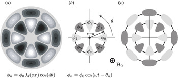
The proposed configuration is shown in figure 1(b). It consists of a capacitive antenna made of $2l$ phased conductive plates positioned perpendicularly to the magnetic field $\boldsymbol {B}_{0}$
 in the plane $z=0$
 and arranged along the polar angle $\theta$
 at

on a ring of radius $a$ . The radius of the antenna ring $a$
 is chosen to match the first extremum of $J_{l}( \alpha r)$
 . Both to have a good impedance matching to the $\pm l$
 TG modes’ components of (4.14) and to minimise the excitation of $\pm l^{\prime }$
 satellites, the size and shape of the $2l$
 plates should be chosen similar to the size and shape of the pattern $| J_{l}( \alpha r) \cos ( l\theta ) |$
 illustrated in figure 1(a) for $l=4$
 . The applied oscillating bias $\phi _n (t)$
 on each of these azimuthally distributed $2l$
 plates must then verify

to preferentially excite the targeted modes

Going further, an improved antenna design could be constructed by adding a second ring of $2l$ phased conductive plates near the second extremum of $J_{| l| }( \alpha r)$
 , as illustrated in figure 1(c).
(a) Bessel TG mode $l=4$ at $z = 0$
 and $t = 0$
 . The radius $a$
 of extrema on the first ring verifies $\alpha a = 5.317$
 . (b) Corresponding capacitive antenna with one ring of phased polarised plates located at $z=0$
 and $r=a$
 . (c) Advanced antenna using two rings of polarised plates.

5. Faraday–Fresnel rotation for WH waves
Whistler waves in a cold magnetised plasma at rest are right-circularly polarised waves whose propagation below $\omega _{pe}$ is sustained by the electron Hall current. Because of the low-frequency nature of these waves, the displacement current in the Maxwell–Ampère equation can be neglected, and propagation is characterised by the dispersion relation given in (2.3). Both antennae designs to excite this WH branch (Stenzel & Urrutia Reference Stenzel and Urrutia2014; Urrutia & Stenzel Reference Urrutia and Stenzel2015b; Stenzel Reference Stenzel2019) and the angular momentum dynamics of these waves (Stenzel & Urrutia Reference Stenzel and Urrutia2015a; Stenzel & Urrutia Reference Stenzel and Urrutia2015b; Urrutia & Stenzel Reference Urrutia and Stenzel2015a; Urrutia & Stenzel Reference Urrutia and Stenzel2016; Stenzel & Urrutia Reference Stenzel and Urrutia2018) have been extensively investigated.
Consider WH electric $( \boldsymbol {E})$ and magnetic $( \boldsymbol {B})$
 fields with helical phase fronts propagating along the $z$
 axis and rotating around this axis:


This electromagnetic perturbation is a solution to the Maxwell–Faraday and Maxwell–Ampère equations


and is associated with an electron velocity

and an electron current

with $\boldsymbol {v}_{0}$ the equilibrium Brillouin velocity given in (3.2). However, the Maxwell–Ampère equation (5.4) can be used to get $\boldsymbol {\nabla }\boldsymbol {\cdot } \boldsymbol {J}=0$
 and from there $j\omega ne=0$
 , so that the current simply writes as $\boldsymbol {J}=-n_{0}e\boldsymbol {v}$
 .
5.1. Dispersion relation
The linearised momentum balance

allows us, with the help of (3.9) and (3.10), to write the electron current as a function of the fields

The operator $\boldsymbol {\nabla }\times$ is then applied to (5.8) to eliminate both the electric field $\boldsymbol {E}$
 and the current $\boldsymbol {J}$
 . Using (3.5), (3.6), (5.3) and (5.4) finally yields the wave equation

One verifies that (5.9) reduces to the classical WH equation (Klozenberg, McNamara & Thonemann Reference Klozenberg, McNamara and Thonemann1965) for $\varOmega =0$ . In addition, (5.9) can be rewritten as

with


The associated second-order algebraic equation $x^{2}-(\beta _{1}+\beta _{2}) x+\beta _{1}\beta _{2} = 0$ has two real roots. The large root is related to TG modes whereas the small one describes the dispersive properties of the WH branch

where we have used the WH ordering $\omega _{ce}\gg \omega$ to obtain an estimate for $\beta _{W}$
 in the last equation. Note that we recover (2.3) for $\varOmega =0$
 , and also that $\beta _{W}( +l) \neq \beta _{W}(-l)$
 for $\varOmega \neq 0$
 . Similarly to the analysis done above for TG modes, further examination shows that the $(\omega _{ce}-2\varOmega )$
 terms are associated with the Coriolis effect in the plasma rest frame (Lehnert Reference Lehnert1962; Uberoi & Das Reference Uberoi and Das1970) while the $( \omega -l\varOmega )$
 terms come from the Doppler effect in the plasma rest frame.
Now, by introducing

such that $K_{+l}=K_{-l}$ for $\varOmega =0$
 but $K_{+l}\neq K_{-l}$
 for $\varOmega \neq 0$
 and

one finds that the Maxwell–Ampère equation for the WH branch reduces to

Note that $K_{\pm l}$ is here simply a convenient variable to write (5.16) and it should not be mistaken for a modified Bessel function. Finally, applying the operator $\boldsymbol {\nabla }\times$
 to (5.16) leads to the wave equation

whose $z$ component writes as

5.2. Solutions as superpositions of eigenmodes with opposite OAM contents
Following a similar approach to that used for TG modes, we look for solutions of (5.18) of the form

that is to say superpositions of eigenmodes with opposite azimuthal mode numbers $\pm l$ , identical radial structure $J_{l}( \alpha r)$
 but different axial wavevectors $\beta _{+l}\neq \beta _{-l}$
 . Both the frequency $\omega$
 and the transverse parameter $\alpha$
 are set by the antenna while the wavevectors $\beta _{\pm l}$
 are determined by the properties of the rotating plasma through the relation

which guarantees that $B_z$ verifies (5.18). Separating the $\pm l$
 contributions, (5.20) can be rewritten as

whose solutions are

5.3. Faraday–Fresnel rotation
Expanding $K_{\pm l}^{2}$ given in (5.14) for the small parameter $\varOmega /\omega$
 and assuming WH ordering $\omega _{ce}\gg \omega$
 yields

Meanwhile, from (5.22),

Plugging (5.23) into this last expression finally leads to the lowest order in $\varOmega /\omega$ estimate for the OAM phase shift

where we have defined the form factor

Similarly to (4.18) which was obtained for TG modes, (5.26) shows that plasma rotation introduces a phase shift between OAM-carrying WH eigenmodes with opposite azimuthal mode numbers, or in other words to FFR. In both instances, the OAM phase shift is proportional to the plasma angular frequency to wave angular frequency ratio $\varOmega /\omega$ , and to the azimuthal wavenumber $l$
 . However, closer examination of (4.18) and (5.26) shows that the form factor $F$
 characterising FFR does depend on $\alpha$
 (i.e. the wave radial structure) for WH modes, while it did not for TG modes.
5.4. Possible antenna design
To conclude this section we point here to a coupling structure designed to launch WH modes of the type (5.19). This type of antenna has been extensively investigated, both theoretically and experimentally, in Stenzel & Urrutia (Reference Stenzel and Urrutia2014) and Urrutia & Stenzel (Reference Urrutia and Stenzel2015b), and we refer the readers to the review paper by Stenzel (Reference Stenzel2019) for an in-depth analysis of their properties.
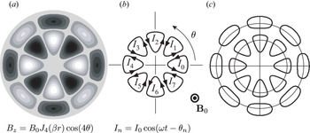
The envisioned configuration is shown in figure 2(b). It consists of an inductive antenna made of $2l$ phased current loops positioned perpendicularly to the magnetic field $\boldsymbol {B}_{0}$
 in the plane $z=0$
 and arranged along the polar angle $\theta$
 at

on a ring of radius $a$ . The currents $I_{n}( t)$
 of these $2l$
 current loops are phased according to

while the radius of the antenna ring $a$ is chosen to match the first extremum of $J_{l}(\alpha r)$
 . The set of parameters $(\alpha ,B_{z0}, l, \omega )$
 are hence all set by the antenna array.
Bessel WH mode $l=4$ at $z = 0$
 and $t = 0$
 . The radius $a$
 of extrema on the first ring verifies $\alpha a = 5.317$
 . (b) Corresponding inductive antenna with one ring of phased current loops located at $z=0$
 and $r=a$
 . (c) Advanced antenna using two rings of current loops.

Both to have a good impedance matching to the $\pm l$ WH modes components of (5.19) and to minimise the excitation of $\pm l^{\prime }$
 satellites the size and shape of the $2l$
 loops should be taken as close as possible to the size and shape of the wave pattern $| J_{l}( \alpha r)\cos (l\theta ) |$
 illustrated in figure 2(a). Alternatively, an improved antenna array can be designed with a second ring of $2l$
 current loops near the second extremum of $J_{| l| }( \alpha r)$
 , as illustrated in figure 2(c).
6. Faraday–Fresnel splitting in a rotating plasma
Consider now a wave packet in a plasma exhibiting both a transverse structure and a longitudinal structure. The rotating phase of the wave packet travels at the phase velocity $\omega /\beta$ along the $z$
 axis, whereas the longitudinal envelope of the wave packet travels at the group velocity $\partial \omega /\partial \beta$
 along this axis (Stix Reference Stix1992; Urrutia & Stenzel Reference Urrutia and Stenzel2015b).
It has been shown in §§ 4 and 5 that plasma rotation introduces a phase shift between TG and WH OAM-carrying modes with opposite azimuthal mode numbers, and that for sufficiently small plasma angular frequency $\varOmega$ the longitudinal wavevectors of these rotating modes write as

In these conditions the longitudinal phase velocity of these modes then write as

with $V_{\varphi }=\omega /\beta | _{\varOmega =0}$ the phase velocity along the $z$
 axis in a plasma at rest $\varOmega =0$
 . Meanwhile, deriving (6.1) with respect to $\omega$
 yields

with $V_{g,\pm l} = \partial \omega /\partial \beta _{\pm l}$ the longitudinal group velocity of these $\pm l$
 modes, and $V_g = \partial \beta |_{\varOmega =0}/\partial \omega$
 the group velocity for zero rotation. Assuming that all factors involving the small parameter $\varOmega /\omega$
 are small, inverting this last relation yields the result

Equation (6.4) shows that in the presence of rotation ($\varOmega \neq 0$ ) the longitudinal group velocity of OAM-carrying eigenmodes with opposite azimuthal wavenumbers – such as the TG and WH modes studied in §§ 4 and 5 – is different, whereas they are equal in the absence of rotation $\varOmega =0$
 . A single envelope wave packet consisting of a mix of these OAM-carrying eigenmodes with opposite azimuthal wavenumbers will hence be split into two envelopes. By analogy with the Faraday splitting of circularly polarised eigenmodes (SAM) (Weng et al. Reference Weng, Zhao, Sheng, Yu, Luan, Chen, Yu, Murakami, Mori and Zhang2017), we refer to this new plasma effect as Faraday–Fresnel splitting (FFS).
7. Conclusions
In this study we have identified and described two new plasma wave effects which arise as a result of plasma rotation. These effects are traced back to the adiabatic coupling which takes place between the OAM of a rotating wave and the OAM of the rotating plasma.
Through an analysis of the response of a rotating magnetised plasma to perturbations carrying OAM, it is shown that plasma rotation introduces a phase shift between OAM-carrying eigenmodes having opposite azimuthal modes numbers. As a result the transverse wave pattern of a wave obtained by superposition of these counter-rotating OAM eigenmodes rotates as the wave propagates. Because of the analogy both with the classical Faraday effect in a magnetised plasma – which relates to the wave's SAM – and the rotatory photon drag known in rotating isotropic dielectric – which relates to the wave's OAM, this plasma effect is referred to as Faraday–Fresnel rotation. The dependence of this phase shift on plasma parameters is derived analytically here for two classical plasma modes, namely, TG and WH modes, as shown in (4.17) and (5.25), respectively.
The difference in longitudinal wavevectors for counter-rotating OAM eigenmodes is further shown to translate to different longitudinal group velocity for each of these modes, as given in (6.4). A direct consequence of this result predicted here is the splitting of a wave packet containing a superposition of these modes, that is to say that the two counter-rotating eigenmodes will be progressively spatially separated. By analogy with the Faraday splitting of circularly polarised eigenmodes (SAM), this new plasma effect is referred to as Faraday–Fresnel splitting.
Searching for the basic physics mechanism behind these effects, a closer examination of (4.12) and (5.14) reveals that rotation manifests itself in the wave propagation properties through two additional terms besides the usual $\omega _{pe}/\omega$ and $\omega _{ce}/\omega$
 terms associated with dispersion. The first one is $(\omega _{ce}- 2\varOmega )$
 and simply accounts for the modification of the magnetic force by the Coriolis force as the rest frame of the plasma is rotating at $\varOmega$
 . The second is $( \omega -l\varOmega )$
 and is a consequence of the rotational Doppler shift as the rest frame of the plasma is rotating at $\varOmega$
 . One is, however, typically used to find centrifugal forces affecting the dynamics alongside Coriolis forces and Doppler shifts in rotating media. One might thus be left questioning what the role of centrifugal forces is here. The answer is not to be found in (4.12) and (5.14) but rather in the transverse structure of the wave. Indeed, since

the maxima of the amplitude $J_{l}(\alpha r)$ are pushed radially outward for higher angular momentum $l$
 . This behaviour is reminiscent of the effect of centrifugal forces. For very high $l$
 cylindrical waves, this pronounced radial outward localisation of the field amplitude is the so called whispering gallery effect associated with centrifugal forces.
Looking ahead, the FFR and FFS effects identified in this study open interesting perspectives. An immediate application would be to use FFR to measure rotation in laboratory experiments, and notably in tokamaks where rotation provides a means to control turbulence and enhance confinement. But, these results also allow for the search for more exotic coupling mechanisms between the plasma wave's OAM and plasma rotation. To name a few, SAM cross-polarisation scattering described by Lehner, Rax & Zou (Reference Lehner, Rax and Zou1989) might be extended to an OAM scheme where the vorticity fluctuation might now be probed through OAM-carrying waves. Another promising direction may lie the Zeeman splitting of the plasmon oscillation identified by Robiche & Rax (Reference Robiche and Rax2008), for which the effect of an additional rotation with OAM eigenmodes rather than with simple SAM eigenmodes should be evaluated. Besides these effects, another important question that remains to be examined is the complementary active or resonant part of the coupling between rotating OAM-carrying plasma waves and the rotating plasma OAM.
Finally, a strong motivation to focus our analysis on TG and WH modes is that they are popular low frequency modes for plasma experiments. This should in turn facilitate experimental efforts to test these findings. Using a pair of antennae such as those described in §§ 4 and 5 in an emitter–receiver configuration, the results obtained here predict that the signal on the receiver should exhibit a double maximum profile as the receiver is rotated along the azimuthal angle, exposing that two $\pm l$ excited rotating waves are differentially dragged by the rotating plasma. It should, however, be stressed that the new results uncovered in this study for TG and WH modes are expected to be similarly found for other branches of plasma waves. One example is compressional rotating Alfvén waves for which a relation akin to that obtained in (5.18) can be derived from ideal magnetohydrodynamics for the compressional magnetic field, suggesting that FFR will be at play. An in-depth systematic analysis of this broader problem is left for future studies.
Editor Cary Forest thanks the referees for their advice in evaluating this article.
Declaration of interests
The authors report no conflict of interest.
Appendix A. Wave and particle spin and OAM in a magnetised rotating plasma
In this appendix we briefly review how to separate SAM from OAM components for plasma waves and particles in light of the complementary dynamical and geometrical points of view. The up/down degree of freedom of the one half-spin $( \hbar /2)$ of the electrons is not considered in this study and SAM refers to the cyclotron motion source of the cyclotron magnetic moment.
The viewpoint adopted here is that separation of both wave's and classical particles’ angular momentum into SAM and OAM components does not stem from a quantum point view, but instead is a simple generalisation of the first König's theorem. König's theorem states that the angular momentum of a system can be decomposed into an external orbital part and an internal part. This internal part is nowadays called the spin part for waves and magnetised charges, even within a classical framework. The analysis of this separation for plasma waves and magnetised particles can be carried both from a geometrical point of view – through the analysis of the transformations properties of the wave field – and from a dynamical point of view – through the analysis of SAM and OAM waves and particles coupling. In this appendix we briefly review (i) the canonical separation between SAM and OAM for a charged particle, then (ii) the geometrical characterisation of SAM and OAM eigenvectors for a vector field and (iii) previous results on the resonant coupling of waves SAM with particles SAM and waves OAM with particles OAM.
A.1. Canonical separation between SAM and OAM for a charged particle
Consider a magnetised plasma column with a background magnetic field $\boldsymbol {B}$ directed along the $z$
 axis and radially polarised by an electric field $\boldsymbol {E}$
 sustaining a guiding centre slow $E\times B$
 rotation at angular velocity $\varOmega$
 . A particle with charge $e$
 and mass $m$
 is described by (i) its position $\boldsymbol {r} = \boldsymbol {R}_{gc}$
 + $\boldsymbol {\rho }_{L}$
 , where $\boldsymbol {R}_{gc}$
 is the guiding centre position and $\boldsymbol {\rho }_{L}$
 the rotating Larmor radius, and (ii) its velocity $\boldsymbol {v} = \boldsymbol {V}_{d}$
 + $\boldsymbol {v}_{c}$
 , where $V_{d} = \varOmega R_{gc}$
 is the guiding centre $E\times B$
 velocity and $v_{c} = \omega _{c}\rho _{L}$
 the cyclotron velocity. This configuration is illustrated in figure 3. The instantaneous angular momentum is given by $\boldsymbol {r}\times m\boldsymbol {v}$
 and its average over the fast cyclotron motion is given by

Introducing the classical magnetic moment of the particle $\mu = m\omega _{c}^{2}\rho _{L}^{2}/2B$ , the angular momentum $\langle \boldsymbol {r}\times m\boldsymbol {v}\rangle$
 is then shown to be the sum of an orbital component $L_{z}$
 plus a spin component $S_{z}$
 associated with this magnetic moment,


where $e/(2m)$ is the classical gyromagnetic factor associated with the ratio of the magnetic moment to the angular momentum.
Cyclotron (SAM) rotation and guiding centre (OAM) $E\times B$ rotations in a magnetised rotating plasma column.

A.2. Geometrical characterisation of SAM and OAM eigenvectors for a vector field
Consider now a wave field $\boldsymbol {A}(\boldsymbol {r})\exp j\omega t$ . From a purely geometrical point of view, the identification of (i) linear momentum, (ii) spin and (iii) orbital momentum wave eigenstates can be guided by the analysis of the transformation properties of the wave under translations and rotations.
Let us examine the change of this vector field $\boldsymbol {A}(\boldsymbol {r})$ under an active (change of the object $\boldsymbol {A}$
 ) or a passive (change of the reference frame and coordinates used to describe $\boldsymbol {A}$
 ) infinitesimal translation $\hat {T}$
 associated with the small vector $\delta \boldsymbol {r}$


with the minus and plus signs associated with the passive and active point of view, respectively. Equation (A4) can be rewritten as a near identity transformation

where $\boldsymbol {I}$ is the identity operator and the linear momentum operator $\hat {\boldsymbol {P}}$
 is defined in the usual way as $\hat {\boldsymbol {P}}=-j\boldsymbol {\nabla }$
 . The eigenvectors of this linear momentum operator $\hat {\boldsymbol {P}}$
 are the plane waves

These waves are also solutions of the Maxwell–Ampère and Maxwell–Faraday equations in an homogeneous linear dispersive plasma provided that $\boldsymbol {\beta }( \omega )$ verifies the dispersion relation. For a finite translation: $\boldsymbol {r}\pm \boldsymbol {a}$
 , the limit $N\rightarrow + \infty$
 of the iterated operator

provides the expected Taylor expansion identity $\boldsymbol {A}( \boldsymbol {r}\pm \boldsymbol {a}) = [ \exp ( \pm \boldsymbol {a}\boldsymbol {\cdot }\boldsymbol {\nabla }) ] \boldsymbol {A}(\boldsymbol {r})$ .
Let us now examine the change of a vector field $\boldsymbol {A}(\boldsymbol {r})$ under an active or passive infinitesimal rotation $\hat {R}$
 associated with a small $\delta \theta$
 rotation around an axis directed by $\boldsymbol {n}$
 ($\boldsymbol {n}^{2}=1$
 ), as follows:

Equation (A8) can be rewritten as a near identity transformation displaying the separation between OAM and SAM operators

The OAM operator $\hat {\boldsymbol {L}}$ and the SAM operator $\hat {\boldsymbol {S}}$
 are thus defined according to the usual relations


where these matrix representations are given on a Cartesian basis $(\boldsymbol {e}_{x},\boldsymbol {e}_{y}\boldsymbol {,e}_{z})$ . Note that, since $\hat {S}_{x}^{2}+\hat {S}_{y}^{2}+\hat {S}_{z}^{2}=2\boldsymbol {I}$
 one recovers the angular momentum rule for a vector $\hat {\boldsymbol {S}}^{2} = s( s+1) \boldsymbol {I}$
 with $s = 1$
 .
The eigenvectors of this angular momentum operator $\hat {\boldsymbol {L}}+\hat {\boldsymbol {S}}$ are the vector spherical harmonics. However, since we are considering a magnetised plasma, vector spherical harmonics cannot be solution of the Maxwell–Ampère and Maxwell–Faraday equations. We have to restrict the transformations to translations along the magnetic field direction and rotations around the magnetic field direction, and the usefulness of the angular momentum operator is reduced to its $z$
 component $\hat {L}_{z}+\hat {S}_{z}$
 . The eigenvectors of the OAM operator $\hat {L}_{z}$
 are $\exp \pm jl\theta$
 with $\theta$
 the polar angle around the magnetic field, while the eigenvectors of the SAM operator $\hat {S}_{z}$
 are the left- and right-circularly polarised wave basis with eigenvalues $\pm 1$
 and $\boldsymbol {e}_{z}$
 with the eigenvalue zero, that is


Solutions of the Maxwell–Ampère and Maxwell–Faraday equations with a phase factor $\exp \pm jl\theta$ have a well-defined OAM in a rotating magnetised plasma when the magnetic axis is also the rotation axis. Solutions of the Maxwell–Ampère and Maxwell–Faraday equations with a polarisation $\boldsymbol {e}_{x}\pm j\boldsymbol {e}_{y}$
 have a well defined SAM. Solutions of the Maxwell–Ampère and Maxwell–Faraday equations with a phase factor $\exp \pm j\beta z$
 have a well-defined linear momentum.
A.3. Resonant coupling
The separation of OAM and SAM contents of waves outlined above can also be analysed through the coupling to the magnetised particles when resonant wave absorption takes place. To illustrate this point we go back to the magnetised plasma column depicted in figure 3. In this configuration the interplay between the wave's SAM and OAM components and particles’ SAM and OAM can be summed up as follows. The wave's SAM (left or right polarisation) is coupled to the cyclotron SAM angular momentum ($2m\mu /e$ ) while the wave's OAM (helical phase fronts) is coupled to the OAM drift rotation of the guiding centre around the axis of the plasma column. These separate couplings, which have previously been identified and studied within the frameworks of rotating thermonuclear trap (Rax et al. Reference Rax, Gueroult and Fisch2017), dissipation in a fully ionised Brillouin flow (Rax et al. Reference Rax, Kolmes, Ochs, Fisch and Gueroult2019) and mass separation with rotating fields (Rax & Gueroult Reference Rax and Gueroult2016), are recalled here.
Consider first a magnetised plasma column at rest and a transverse wave with $L_{z}=0$ and $S_{z}\neq 0$
 , that is to say with a simple oscillating phase factor $\exp j( \omega t-\beta z)$
 and a polarisation component corotating with the cyclotron motion. The absorption of this wave by a population of charged particles with mass $m$
 and charge $e$
 leads to (i) energy $\mathcal {E}$
 , (ii) linear momentum $P_{z} = mv_{z}$
 and (iii) cyclotron angular momentum $S_{z} = mv_{c}^{2}/\omega _{c}$
 exchange. Here $v_{c}$
 is the cyclotron velocity around the magnetic field, $v_{z}$
 the velocity along the magnetic field and $\omega _{c}$
 the cyclotron frequency. For a collisionless resonant absorption through the classical Doppler shifted harmonic cyclotron resonance,

the absorption of an amount of energy $\delta \mathcal {E}$ by particles is associated both with a transfer $\delta P_{z} = m\delta v_{z}$
 of linear momentum,

along the magnetic field lines and with a transfer $\delta S_{z}=mv_{c}\delta v_{c}/\omega _{c}$ of SAM defined by (A3),

around the magnetic field lines.
Consider now wave absorption in a magnetised rotating plasma column, and assume this time a wave with a helical phase factor $\exp j( \omega t-l\theta -\beta z)$ verifying the eigenvalue relations (A12) and (A6). This wave has an OAM content such that $L_{z}/P_{z}=l/\beta \neq 0$
 . In addition to the previous SAM coupling leading to $\delta S_{z}$
 , an OAM coupling takes place with the drift $E\times B$
 rotation of the guiding centre. The transfer of energy $\delta \mathcal {E}$
 from this wave to a particle is associated with a transfer of OAM around the $z$
 axis

Equations (A15), (A16) and (A17) are simple consequences of energy, linear momentum and angular momentum conservations

and

Rather than examining these resonant exchanges of linear and angular momentum, we have chosen in this study to consider the adiabatic interaction of waves and particles, that is to say the coupling between wave OAM and plasma $E\times B$ rotation on cold dispersion, as an analogue to the coupling between wave SAM and plasma magnetisation on cold dispersion which yields the classical Faraday effect.