

In 1849 George Wilson wrote that ‘the history of the English air-pump is in great confusion’.Footnote 1 Today, 160 years later, there are still many unknown areas, for example regarding Francis Hauksbee and his double-barrelled air-pump. This pump is well known to modern instrument historians but Hauksbee's background and the origin of the pump is not. This article reveals the prehistory of the device.Footnote 2
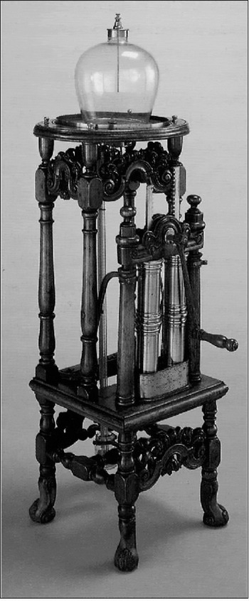
The importance of the air-pump for the scientific advances of the British Enlightenment is evident from Joseph Wright's painting An Experiment on a Bird in the Air Pump (1768).Footnote 3 Hauksbee's air-pump, depicted in part in this painting, is known as an efficient and stunning masterpiece with ornaments and beautiful woodcarvings. It is not difficult to see why it has attracted so much attention (see Figure 1). Moreover, Francis Hauksbee himself (1660–1713) is a fascinating character who has been variously described as instrument-maker, draper, physicist, scientist, inventor, experimenter, natural philosopher, lecturer, author and curator, as well as student of Robert Boyle (1627–91). Modern studies have often emphasized his attempts to explain electric phenomena and his role as a demonstrator in the Royal Society and in public lectures.
Hauksbee's double-barrelled air-pump (1705). The Royal Society, London.

The lack of information on Hauksbee's early activities, especially as to where he had achieved such a high competence in instrument-making, has led to series of speculations and misunderstandings. Wilson explained much of the confusion about Hauksbee's air-pump through the imprecision of a series of writings from the second half of the eighteenth century onwards. I have found the error to be even older, however. For example, a much-consulted source on natural philosophical issues in this period is John Harris's Lexicon Technicum, first published in 1704. While the first edition contains a detailed text on Hauksbee's first air-pump (a single-barrelled one), the 1737 edition, which many historians have used, omits this text and reprints only Hauksbee's own description of the double-barrelled pump from 1709. Here Hauksbee's name is omitted and his account inserted in a text on Boyle's pumps, and in such a way that it gives the impression of this pump being ordered by Boyle and manufactured by Robert Hooke (1635–1703).Footnote 4 The commonest modern idea is that Hauksbee had worked as one of Boyle's technicians and that his double-barrelled pump was simply an improvement of the foot-operated air-pump with two cylinders of 1682 of Denis Papin (1647–1712).Footnote 5 Historians of science have characterized Hauksbee's obscure background in various ways, as for example does Henry Guerlac, who wrote that Hauksbee ‘emerged from obscurity’.Footnote 6 According to John Heilbron, ‘it is unknown how Hauksbee had prepared himself as an experimenter and how he came to Newton's attention’.Footnote 7 Richard Westfall asserted that ‘we know nothing of Hauksbee's origin and background’Footnote 8 and that ‘no one today seems able to define precisely what his improvements of the air-pump were’.Footnote 9 In sum, the modern popular account holds that
Hauksbee's first public appearance took place at a meeting in the Royal Society in London on 15 December 1703, invited by Isaac Newton (1642–1727). That evening he performed an experiment on light emitted from mercury with his double-barrelled air-pump, which was an improved version of Papin's pump. On the following meetings he performed series of experiments originally undertaken by Boyle.
However, by approaching the sources from a technical point of view, using my experiences as a former laboratory technician as well as those achieved in examination and restoration of scientific instruments, I soon became uncertain of the soundness of the standard account.Footnote 10 The leaps from Boyle's to Hauksbee's practice, and from Papin's to Hauksbee's pump, seemed to me huge and discontinuous. For example, an examination of a few extant Hauksbee pumps suggested that there were technologies involved not found in Papin. Some important events must have taken place in Hauksbee's career that enabled him to make such a beautiful and complicated instrument and to perform his variety of experiments. I argue here that Hauksbee's air-pump stemmed from cupping and anatomical instrument-making. Further, I make it clear that his first air-pump was not the celebrated double-barrelled model but a simpler single-barrelled one based on technologies taken from his cupping devices.Footnote 11 A combined engine that could be applied as an air-pump, a condensing engine and an anatomical injector served as a transition between the fields. Hauksbee had pursued these activities since at least 1699 and his first air-pump was made available in 1702. I also show how Hauksbee became a public figure in London long before he was called to the Royal Society. Moreover, I found no evidence of a possible connection between Hauksbee and Boyle.
Except for Shapin and Schaffer (1985)Footnote 12 and articles by Stroup (1981)Footnote 13 and Van Helden (1991),Footnote 14 there are rather few in-depth studies of the history of the early air-pump. Here I draw upon these works, as well as on Hauksbee's own book, his articles, the Journal Book of the Royal Society, newspaper advertisements, lecture syllabi, Harris's Lexicon Technicum and the examination of objects. In Hauksbee's case the material found in the archives of the Royal Society, as well as in sales advertisements, has not been fully appreciated by historians.
However, a few details of Hauksbee are known. He was born in Colchester in 1660, was apprenticed as a draper to his elder brother John, and belonged to the Draper's Company in London. He lived in Queen's Head Court in Giltspur Street, London, but moved to Wine Office Court in 1710 and to Hind Court in 1712, both off Fleet Street. Further, he was engaged by the Royal Society to perform experiments during their weekly meetings; wrote fifty articles in the Philosophical Transactions; issued a book, Physico-Mechanical Experiments on Various Subjects;Footnote 15 gave public lectures on natural philosophy (from 1705); manufactured and sold scientific instruments; and had several apprentices and associates.Footnote 16 He died in London in April 1713. The period in which he was active was characterized by great political, economic, social, technological and scientific developments. In London there was a growing market for a range of new commodities and activities, including scientific instruments, technical literature and lectures in a variety of fields.Footnote 17 Thanks to the lapse of the Printing Act at the end of the previous century, a series of newspapers started to emerge. Even though these newspapers initially consisted of only one sheet and were published two or three times a week, they played an important role in developing society. Typical of these newspapers was a diverse number of advertisements ranging from announcements of wonder-pills for all kinds of diseases to notices of books on law and theology. Newspaper advertisements, most found in the the Daily Courant (the first daily newspaper in London, from 1702), have previously been used as a source for studies on Hauksbee, especially on his role as a public lecturer.Footnote 18 However, I found that Hauksbee at the same time advertised series of medical and philosophical instruments for sale in other papers, like the Post Man and the Flying Post, thus keeping advertisements for lectures and instruments separate, a fact that seems to have been previously unknown or unremarked.
For those who could afford it, a variety of technical and scientific books, instruments and arrangements concerning natural philosophy was available. The momentum of such public interest in scientific inquiry was furthered by the popular coffee houses established throughout the city. Here newspapers were read and discussed, goods bought and sold and natural philosophy taught in public lectures (from 1705).Footnote 19 One characteristic of these lectures was that time and place, as well as the required course syllabi, were announced in the newspapers, another was the use of printed material and experiments.Footnote 20 Science was no longer the preserve of a small elite, but was made understandable and accessible to the public.Footnote 21
The air-pump and its importance for seventeenth-century natural philosophy is well known from Shapin and Schaffer's work, discussing Boyle's efforts to establish a way to produce, express and spread knowledge obtained experimentally with an air-pump.Footnote 22 My approach is different. The aim of this article is to describe Hauksbee's way to the air-pump by studying technical matters, a development that proved to be crucial for the construction of the double-barrelled pump and for pneumatics generally in the eighteenth century.
Theory and practice of cupping
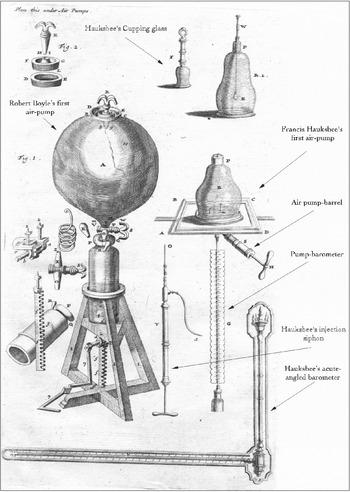
In 1704 John Harris (1667–1719) portrayed Hauksbee in Lexicon Technicum as an ‘Ingenious and Industrious Artificer’ who made mathematical and philosophical instruments, including air-pumps. This pump, with all its crucial components, was described in detail. Hauksbee was also referred to under the entry ‘Cucurbitula’ – cupping-glasses. On a plate with illustrations of pneumatic apparatus, Harris gave a picture of a small cupping device made by Hauksbee, as well as one of his air-pump (see Figure 2).Footnote 23 Here I describe the relationship between these two items.
Pneumatic instruments. From J. Harris, Lexicon Technicum, 1st edn, London, 1704. Explanations and arrows are inserted by the present author.

Ancient methods of cupping and blood-letting were a common form of medical therapy in the early eighteenth century.Footnote 24 According to Galenic medicine, the mental and physical condition of a person was dependent on the balance between the four humours of the body: blood, phlegm, black bile and yellow bile.Footnote 25 These fluids correlated with the four elements: Earth, Water, Fire and Air, representing dryness, wetness, heat and cold. It was generally believed that sickness could be caused by an imbalance of these fluids, and the remedy was to remove excess amounts by blood-letting and cupping to restore the equilibrium. Harvey's discovery of the circulation of the blood in 1628 had in fact not diminished the popularity of these methods.Footnote 26
The first known evidence of Francis Hauksbee's engagement in supplying equipment for this popular practice is an advertisement in the Post Man of 31 January 1699: ‘A New way of Glass Cupping performed without Fire, Lamp, or Mouth Suction, Invented by F. Hauksbee, who liveth in Queens Head Court in Guilt Spurr Street, just without Newgate.’Footnote 27
Traditionally, there existed several ways to free the patient from these excessive and harmful humours. Leeches could be placed on the skin to suck out the ‘ill’ blood, veins could be opened with special knives (fleams) for draining a required amount of blood, or cupping could be employed.Footnote 28 In cupping, the skin was normally punctured with a knife before a heated glass cup was placed over the assigned area. As the air inside cooled, the cup would ‘stick’ to the skin through the reduced pressure produced as the air contracted. This ‘vacuum’ sucked the blood out through cuts in the skin and away from the internal parts where it was thought to congest.Footnote 29 The glasses were normally heated over a candle or with a torch or spirit lamp. Another method was to burn a piece of paper or tow inside the cup and heat its internal air before the cup was applied to a patient.Footnote 30 Instead of using the heating and cooling of air to create a vacuum, similar effects could be achieved through mouth suction, where special cups, often made from horn, were used.Footnote 31 Hauksbee described his particular method as different from these traditional ones, and declared it the most effective ever put into practice. According to the advertisement, this method received the approval of all who saw it to be the best and was now being offered to ‘gentlemen proper for its use, to the Benefit of the Publick’.Footnote 32 He also invited physicians and surgeons to his house for demonstrations. Without giving any details, Hauksbee claimed he himself had invented the method, one so simple that anyone who observed it was capable of repeating it.
A few months later Hauksbee published another advertisement, now revealing more details.Footnote 33 He was selling several sorts of glasses, larger or smaller for a variety of uses, including the cupping of whole fingers or toes. Fleams and other accessories connected to the practice were also available. It becomes clear that the crucial object was a small ‘Engine’ which could be used with several glasses at a time. In examining these and later announcements, I found that this engine must be a small syringeFootnote 34 that could be attached to the top of a cupping-glass, an interpretation visually confirmed by Harris (Figure 2). When a glass had been placed over the area to be cupped the operator could evacuate the air contained in it simply by pulling the handle attached to the sucker. The glass could then be left in place after pumping, while the syringe was removed and applied to the next. The suction was produced by the action of an exhausting-syringe, instead of by cooling and contracting air.
Hauksbee's utensils
To be as easy to operate as Hauksbee claimed, these cupping utensils required several features not explicitly mentioned in the advertisements. One characteristic of cupping practice was that the glasses should be kept on the skin for some time, giving the ‘sick’ blood time to get out. For this to be possible with Hauksbee's glasses, they had to be left in place with a reduced pressure within once the pumping was finished. Hauksbee made it clear that a ‘single engine’ could be used with several glasses during a treatment, which implies, though this is never mentioned, that the glasses must have been equipped with a closing mechanism to shut them after pumping.Footnote 35 This was necessary to prevent air from rushing into the glasses when the syringe was removed. After a glass was sufficiently pumped the syringe would be disconnected and used on the next glass.
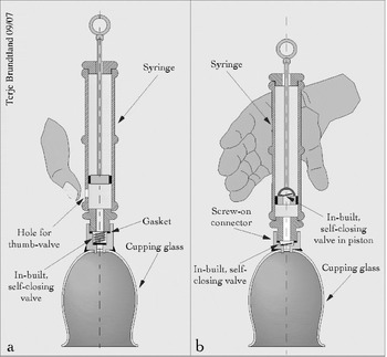
We know that the first syringes were equipped with a small hole on which ‘the thumb was acting as a valve’, indicating that the air-stopping mechanism in the glasses was a valve intended to shut automatically when the pressure in the syringe became higher than that in the glass.Footnote 36 Based on this information a reconstruction of Hauksbee's first cupping system is possible. The hole must have been located in the lower end of the syringe, penetrating the wall just above the position of the upper edge of the piston when this was pushed to its innermost position. The syringe was fastened to the brass cylinder on top of the glass, which contained the self-closing valve (see Figure 2F, and the reconstructed cupping-glass in Figure 3a).
Francis Hauksbee's first cupping-syringe, with thumb-valve (January 1699) (a); Hauksbee's second cupping-syringe, with automatic valve in the piston (January 1701) (b). Drawings by the author.

The operator then simply had to place the cup on the patient's body while holding the syringe with his left hand, the thumb covering the small hole. The plunger was then pulled outwards with the right hand, sucking the air out of the glass. With the piston at the outer end, or as far out as was needed to give the required suction, the thumb was then lifted, causing the outside air to rush into the syringe and forcing the self-closing valve on the glass to close automatically, thus preserving the vacuum. If another stroke was required, the sucker had to be pushed inwards to the start position and the thumb placed over the hole once more so that a new sequence could begin.
Another question arises from studying this practice: if the same syringe could be used on several glasses during the treatment of a patient, it must have been possible to connect and disconnect the glasses in a reasonably short time to avoid stress on the patient and the operator. This also had to be accomplished without excessive force, so that the risk of the cups coming loose from the skin was minimized. Finally, the connection had to be leak-tight. One possible design which could meet these conditions, matching Hauksbee's promises about simplicity, would have been a screw-on–screw-off system made leak-tight with a leather gasket. This would make connection and disconnection fast and reliable, providing the leather seal was kept wet with an occasional drop of water or oil.
Origin
Hauksbee did not reveal much about the structure and the background of his devices in the early sales advertisements. But there exist two articles in the Philosophical Transactions from the same period that help. In June 1699 Mr Thomas Luffkin of Colchester,Footnote 37 Hauksbee's home town, published a letter about some old numerical figures on an escutcheon in a house there.Footnote 38 The same letter had a note about ‘a small air-pump’ that could be applied to cupping-glasses made by Luffkin's brothers. In an article in October the same year he gave a detailed account of these items, including an illustration.Footnote 39 I have not been able to find any direct links between Hauksbee and the Luffkins in the contemporary literature, but there are so many parallels here that I argue for a connection between them and for a common origin of the devices.
Hauksbee came from a family of drapers in Colchester and the old figures described by Luffkin were found in a house in Colchester belonging to another draper family, the Furlys. It is unlikely that they did not know each other.Footnote 40 The Furlys may in turn represent the link between the Luffkin and the Hauksbee families. Furthermore, the chronology agrees. Hauksbee advertised in January and May 1699, while Luffkin wrote in June and October. It becomes clear in the first article that Luffkin already had a technical description about the items available and that this was the account published in October. This means that in Colchester Luffkin had tested and documented his instrument in the first half of 1699, which coincided with Hauksbee's activities in London. The most remarkable comparison is, however, that the instruments seem to be more or less identical. Both used a syringe with a solid piston to evacuate the cupping-glasses, both could easily mount and dismount the syringe from the glasses and both had a self-closing valve on top of the glasses. Even the function of using the thumb as a valve on the syringe was mutual. Therefore Luffkin's notes and diagrams may shed light on Hauksbee's early instruments.
Did it work?
Hauksbee's cupping-syringes suggest a connection between the traditional practice of blood-letting and cupping and natural philosophy. But did his contrivances work? If they did not, the whole enterprise might have been regarded as a fad and Hauksbee some sort of a quack. There were many such in the period and Hauksbee's advertisements were often surrounded by announcements for all kinds of medicines and magic pills.Footnote 41 If Hauksbee's devices did work, however, they represent an important link in the chain leading up to his well-known air-pump.
Some of the benefits of Hauksbee's and Luffkin's concept seem obvious, such as the absence of heat. With traditional methods, there was always a danger that the patient might be scorched. If the air inside the glass were heated over a candle or with a torch, great care had to be taken not to heat the rim excessively. Further, if a lighted tow or paper were put into it to expand the air, the cup had to be applied quickly to the body before the air cooled, with the consequence that hot ashes could fall on the skin.Footnote 42 To succeed with a treatment a reheated glass had often been applied to the same place several times, increasing the risk of burning the skin. If a glass were not hot enough, on the other hand, the suction effect on the skin would be insufficient, or the glass might not stick to the skin at all. Another characteristic of the old method was that no further control of suction, thus of the efficiency of the operation, was possible when a heated glass was placed on the skin. With Hauksbee's method the patient did not need to fear any of this or experience painful burning. It would become unnecessary for the operator to care about fires and lamps, or even to master the difficult task of heating and applying the glasses quickly to the skin. Here the operator had several options not found with the old method. First, he could control the pressure in the cup by the length or number of plunger strokes. Second, he could perform controlled, successive pumpings. Finally, he could obtain a much lower pressure in the glasses. These options would give the operator better control over the amount of blood and humours to be drawn from the skin. In cases where repeated suctions on the same location were seen as favourable, the glasses could be left in place and simply ‘re-pumped’. In his second advertisement (May 1699) Hauksbee says that the pumping could be ‘continued to any degree the operator finds necessary’.Footnote 43 So in contrast with the difficult and cumbersome way of cupping by heat or mouth suction, this invention was easy and convenient to use.
Harris concluded his entry on cupping in Lexicon Technicum (1704) with the following judgement: ‘Now in England we commonly use cupping-glasses without fire, which is evacuated by a small syringe … invented by Mr. Hawksbee.’Footnote 44 But it remains unclear to what extent Hauksbee's method reformed cupping practice. Presumably it represented a complement to existing methods, as both were regularly reported during the eighteenth century. More important, however, is the broader development through which this technology was transferred to the air-pump and proved crucial to its development.
Improvements
In Hauksbee's advertisements from 1699 some efficient and simple instruments that were approved by surgeons and physicians in London were exhibited. The subsequent descriptions in later announcements, however, indicate that problems must have arisen, requiring Hauksbee to modify and improve his devices. No advertisements from Hauksbee between May 1699 and January 1701 are to be found. Then on 4 January 1701 he published a note in the Post Man about ‘The new way of cupping’.Footnote 45 This text was very much the same as his first advertisements, describing glasses of several sorts and sizes applicable to any part of the body, ‘which were so easy to use that any person upon sight was capable of doing it’. Further, he offered a new instrument for scarifying the skin, which made seven incisions at once, said to be less painful to the patient and quicker and more certain for the operator.Footnote 46 The most important difference, however, was a statement that the utensils ‘are now being absolute perfect, and will never be out of order’.Footnote 47 This was due to amendments Hauksbee claimed he had recently made, but no details were provided. Former customers were invited to come back and get their purchases modified for twelvepence per engine and sixpence per glass. This shows that modifications or improvements had been made in both the glasses and the syringe. To distinguish between the old and new sort, Hauksbee described the old ones as those where the thumb is used as a valve on the engine. This suggests that the modification of the syringe consisted in eliminating the thumb-valve. The new syringes could therefore not have been supplied with this hole. A valve using the thumb as a closing mechanism can hardly be made simpler, so the solution must have been to replace it with a fully automated one, making the use of the thumb unnecessary. No details of the changes on the cupping-glasses were given. The expressions ‘now being absolute perfect’, and ‘never out of order’ sound like commercially motivated exaggerations. On the other hand, Hauksbee admitted problems with his first utensils, and it seems that the amendments had given him new confidence. Now he also offered his products to gentlemen living outside London who were unable to come and see it demonstrated in person. Supply of written instruction would be sufficient to learn the techniques.
I suggest that these amendments consisted of a self-closing valve inserted in the piston of the pump and an improved self-closing one in the glasses. Hauksbee gave no details of either the old or the new valves. We know about Luffkin's valve in detail, however, and Hauksbee's acknowledgements of problems strengthen the idea that both were of a similar construction, for Luffkin also admitted problems with the valve. In addition to the syringe, the glass and the valve, Luffkin described a stopper plug that could be screwed into the connector where the syringe was normally attached, to prevent air leaking into the glass, ‘if there should happened to remain any Fissures at the valve’.Footnote 48 Luffkin's valve consisted of five small parts, including a brass spring and two pieces of leather. The crucial component in such valves is the spring (Figure 3a). The spring being too hard, the valve could be difficult to open, preventing the glasses from becoming sufficiently pumped. Conversely an overly soft spring would make the valve difficult to close, allowing leaks. The result in both cases would be problems with getting the glass to stick properly to the skin. Luffkin's unreliable and cumbersome scheme – the use of the extra stopper – did not fit well with Hauksbee's promises of simple instruments. If it were a similar product that Hauksbee tried to sell to cuppers in London and in the countryside, he would clearly have received complaints. The phrase ‘never out of order’, describing Hauksbee's modified cupping-glass valve, must then be seen in contrast to these shortcomings. There are few hints on how it was constructed, but we know that Hauksbee later used a piece of flexible bladder-skin to cover the orifice in the valves, a solution that could have been introduced at this occasion.
While the new valves on the glasses were more efficient than the older ones in preventing air from leaking in, that in the sucker made the whole operation easier than before. There is, again, little information on this valve. If it were made like the one in the glass, the skin must have covered the orifice during outward motions of the plunger and be lifted up during inward movements due to differences in air pressure over the elastic bladder-skin (see Figure 3b). It would thus, as usual, pump air out of the cup on an outward stroke. When the piston was again moved inwards, the air in the syringe would start to compress and the self-closing valve on the glass would close, keeping a vacuum inside. The valve in the piston would open by the same compression, however, and atmospheric air would fill the syringe and exert further pressure on the cupping-glass valve, so that the piston could easily again be moved back to the start position.
With these new amendments the operator had simply to screw the syringe onto a glass of the required size and shape, then place it on the patient's skin. Holding the syringe with one hand, he could pull the handle of the sucker outwards with the other, without having to consider the correct position of the thumb or his ‘holding’ hand. When the preferred degree of suction in a glass had been obtained, the syringe could simply be moved to the next one. This was even easier than using the thumb as an opening and closing mechanism on the syringe, and very different from the traditional methods of fire, lamp or mouth suction.
A possible motive here is that Hauksbee developed these gadgets in response to complaints from customers who, having bought his first version of the cupping utensils, did not find them as reliable and easy to use as promised in his advertisements. The idea of these small components, which later became crucial for his air-pumps, must have been conceived some time between the middle of 1699 and the end of 1700.
The market
Hauksbee's cupping device was the first practical application I have found of the ‘Vacuum Boyleanum’ in England. It was also the first use of the technique in commercial products for a public market. Already, at this stage, at the turn of the century, Hauksbee showed outstanding skills in vacuum technology. The difference between the attitudes of Boyle and Hauksbee to the hardware is striking. While Boyle made great efforts to describe and explain his air-pumps to the readers in text and illustrations, Hauksbee's devices were portrayed as self-explanatory. It is also clear that people at other locations who had only read Boyle's publications never succeeded in replicating his experiments: it proved vital first to observe the experiments being undertaken with Boyle's original equipment.Footnote 49 In contrast, Hauksbee sold his instruments to people in the countryside by mail order, where a written instruction ought to be sufficient to learn how to use them.Footnote 50 Here the tacit knowledge obtained by seeing and doing air-pump experiments was no longer necessary. The technology had become refined and most of the required skills and gestures were ‘built into’ the machine.
One reason for developing and refining this technology could have been Hauksbee's continuous connection with his customers, including sale, complaints, improvements and then sale of modified products. Although there is little direct information about the buyers, there must have been a market for Hauksbee's cupping utensils, since he and his successors made and sold such devices throughout their careers. An obvious disadvantage with these commodities must have been the cost. Hauksbee did not give any prices, but as the cost of a syringe with glasses can be estimated to be about one pound, his invention would not have been affordable to everyone in the cupping business.Footnote 51 (The average annual income for a craftsman in this period was about twenty to thirty pounds, and between one and two hundred pounds for surgeons and apothecaries.Footnote 52) This points to the possibility that most customers belonged in the middle and upper classes in London.
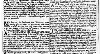
We know, for example, that cupping and blood-letting were among the services provided in the popular London public bathhouses, often in combination with coffee houses, also called ‘bagnios’ or ‘hummums’ (Turkish baths).Footnote 53 In the first decade of the eighteenth century many of them announced cupping ‘in the new manner’ or ‘by modern instruments’. Previously, modern authors such as Thomson, Lillywhite and Bennion, seemingly unaware of Hauksbee's new method of evacuating the glasses, have identified this new element of the cupping method to be the use of scarificators.Footnote 54 Here, however, I argue that the ‘new way of cupping’ in the bathhouses included the use of the small air-pumps (syringes) invented by Hauksbee. For example, in the Hummums of Covent Garden there was a ‘Man and a Woman who cup after the newest and easiest method’.Footnote 55 When Ned Ward (1667–1731) visited this place around 1700, he vividly described how the air was ‘drawn out’ of the glasses to make them stick to his back but without mentioning the particular method.Footnote 56 The expression ‘drawn out’ corresponds perfectly, however, with the operation of a syringe plunger pulled outwards to evacuate a cupping-glass. And in the Queen's Bagnio, in Long Acre, men and women could be ‘cupped in the best perfection, there being the best and newest instruments for that purpose’.Footnote 57 Advertisements from hummums and Hauksbee could also appear next to each other in the same paper.Footnote 58 While the text in Hauksbee's advertisement read ‘glasses for the new and most approved way of Cupping, … and the operation so easy’, the one for the hummum announced ‘cupping after the newest and easiest method’. Moreover, Hauksbee himself always did refer to the use of glasses and syringes (small air-pumps), not to the use of scarificators, as the ‘new way of cupping’ (see Figure 4).
Cupping advertisements. Post Man, 10 October 1706. The parallels between the advertisement for the hummums (right) and Hauksbee's attention to cupping methods are underlined.

The novel cupping method of the bathhouses of London in this period must have encompassed both syringes and scarificators. The owners of the bathhouses, among them surgeons and apothecaries, would thus have been important customers of Hauksbee, while the bathhouses functioned as testing grounds for his inventions. Most importantly, however, the invention, production, advertising and sale of cupping utensils, with all their advantages and disadvantages, must have provided Hauksbee with resources for developing other instruments, as well as making him known to the public. The valve principle in these devices became crucial for the design of his air-pumps and can be seen as an example of the effect of consumer demand on scientific innovations.
The new engine
Hauksbee was a keen advertiser and presented his products at least twenty-five times between January 1699 and July 1703 in the Flying Post, the Post Man, the Gardener's Almanack and the Double Ephemeris.Footnote 59 In January and May 1699, and from January until September 1701, Hauksbee's main concern had been to make his excellent cupping utensils known to the public. In November 1701, however, an important new item was added to the product list:
Also an Engine which serves as an Air pump for making experiments in Vacuo, performing them with ease and exactness, without the use of Cement or Stopcock. The same Engine to be used for compressing air to the greatest violence, and Likewise is a siringe for the injection of Wax, Mercury or Air in Anatomy, with other qualifications beyond any Instrument yet made for that purpose.Footnote 60
This contrivance served as a transition from the cupping-syringe to the air-pump and was a move towards a product range that would become typical for him, including cupping utensils, air-pumps, condensing engines (air-compressors) and anatomical injectors. This is the earliest known evidence of Hauksbee's production of air-pumps and engagement in experimental philosophy, and represents the beginning of a commercialization of air-pumps in England.
Size and form
Hauksbee described the engine as an apparatus that could serve as an air-pump capable of making experiments in vacuum with ‘ease and exactness’ and ‘without the use of cement or stopcocks’. These characteristics later became part of the standard description of his air-pumps. What sort of instrument it was becomes clear, as he described it as a ‘siringe’ when it was used for injections. This was in fact the first time Hauksbee explicitly stated that he was dealing with syringes, but, as I have shown, the key component in his previously advertised cupping utensils was just such a device.
The novel engine could not have been a simple cupping-syringe applied to a new purpose, however, but had to be a syringe of comparable size to the barrel of Hauksbee's separate air-pumps and siphons, which came later (Figure 2). This is evident from the nature of its various functions, such as the possibility of making experiments in vacuum. This shows that such undertakings were already on Hauksbee's agenda at the end of 1701. Hauksbee had earlier stressed that the cupping-syringes were small engines which of course would be sufficient to evacuate the relatively tiny volumes in the cupping-glasses. But most of the classical vacuum experiments required a volume much larger than a cupping-glass. For example, the spherical receiver on Boyle's first air-pump contained thirty wine quarts, or about thirty-five litres.Footnote 61 Based on the size of the various components in Figure 2, the volume of Hauksbee's air-pump receivers can be estimated at ten or eleven litres, requiring between twenty and thirty minutes' pumping time with an ordinary syringe – an arduous task. If such a receiver were, for example, evacuated in five minutes, a syringe volume of five to six times larger than a cupping-syringe would be needed.Footnote 62 This is within the same size range as that indicated by the pump-barrel in the engraving in Lexicon Technicum. The fact that the quantity of material injected into pathological specimens was normally much larger than could be held by a cupping-syringe also indicates that the new engine was considerable larger.Footnote 63
Functions
To be able to combine an air-pump, compressor and injector in one instrument, some major alterations had to take place to allow transformation from one application to another. Since the engine could be used as an air-pump that worked without stopcocks, there must have been some sort of automatic valve in the piston. To be functional, it had to close when the plunger was pulled out and open when it was pushed in, as in the case of the valve of the cupping-syringe. A piston like this would not have served any purpose if the engine were used for compressing air. Such a piston had to be either solid or supplied with a valve mounted in a way that opposed the valve in the air-pump, closing during the inward strokes and open during the outward.Footnote 64 If the syringe were used for injecting air, it simply had to be arranged like the compressor. A solid piston was, however, required when it was used for injecting wax or mercury.
Since these relatively different functions were possible with the same engine, the main component must in fact only have been the syringe cylinder itself and the plunger rod – something like the cupping-syringe, but larger. A few different pistons were required, as well as several front end-pieces that could be fastened to the barrel, allowing it to be connected to various external apparatus. The engine-user must have been able to connect it to a receiver for vacuum experiments through a component containing another valve, and to a cylinder or spherically shaped metal container for confining the pressurized air, as well as supplying it with a cannula to transform it into an injector.
The idea of using a single engine as a combined air-pump, compressor and injector seems rather clever but must have been difficult to use in the long run. Repeated alterations would also create wear on threads and gaskets, increasing the possibility of leaks and breakdowns. Such inconveniences could have been a motive for developing the instruments further. The multipurpose engine was advertised for a final time in April 1703, being replaced by separate air-pumps, condensing engines and medical injectors.Footnote 65
Hauksbee's first air-pump
After the ‘multipurpose’ engine had been available for about a year, it experienced competition from another instrument capable of similar functions. In October 1702 Hauksbee modified the advertisement text: ‘Also Air pumps, with Apparatus for making all manner of Experiments proper to be made in Vacuo Boyliano, with ease and exactness, without the use of Cement or Stopcocks’.Footnote 66
According to this announcement Hauksbee offered separate ‘air-pumps’ for sale (note the plural), including apparatus for making all sorts of experiments in the vacuum. The air-pumps were described in the same terms as the ‘air-pump mode’ of the combined engine, as Hauksbee claimed they could perform experiments with ease and exactness and without cement and stopcocks. There is a close relation between Hauksbee's cupping utensils and air-pumps, where the combined engine acted as a link. The following sections describe Hauksbee's first air-pump, showing how his experiences with cupping devices regarding airtight seals, screw-on connectors and valves became crucial for its success.
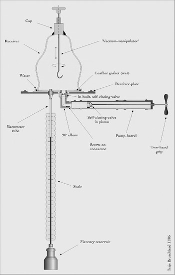
The best contemporary account of this pump is given in Lexicon Technicum (1704), containing an illustration and a textual description (Figure 2). The content more or less matches the pump description of 1702 (above) as well as that of the combined engine, indicating that Hauksbee's air-pump concept was already developed in 1701. It consists of a single barrel or syringe (S) mounted horizontally under a square board (A, B, C, D), which also supports the vacuum recipient (R). The pump is supplied with a mercury barometer (G) attached under the pump plate for monitoring the pressure inside the recipient. Another glass receiver (R.2.) and a cupping-glass (F) are also shown. A drawing of the principal parts is given in Figure 5.
Francis Hauksbee's single-barrelled air-pump (1702). Drawing by the author.

Volume and shape
Based on the relative size of the various objects in the illustration, including the barometer scale (seventy-six centimetres long), the volume of the pump barrel and the receiver can be estimated at 270 and 11,000 cubic centimetres respectively. A cupping-syringe and a glass had volumes of about fifty and a hundred cubic centimetres.Footnote 67 Apart from the size, there are many parallels between Hauksbee's cupping concept and his air-pump. First, the function of the cupping-glass and the pump recipient was more or less identical. Both were used to confine the vacuum created by a pump and to offer a space for the objects in question, either the diseased blood or the item subjected to air-pump experiments. Second, both were made of glass, which gave the operator the chance to see and control the various phenomena, an important advantage compared to opaque cupping-horns and, for example, Otto von Guericke's solid copper spheres.Footnote 68 Another similarity was the shape. Early vacuum receivers were often depicted in the form of large cupping-glasses, for example those by Robert Boyle.Footnote 69 Christiaan Huygens (1629–95) described some of his receivers as shaped like cupping-glasses.Footnote 70
The parallels are even more evident in the cupping-syringe and the pump barrel. In spite of their different dimensions, both the multipurpose engine and the horizontal barrel on Hauksbee's first air-pump were in fact large syringes, working on the same principle.
Sealing leaks
Another connection between Hauksbee's cupping-glasses and air-pumps is the way in which he solved issues of sealing. In all his advertisements from 1701 to 1703 Hauksbee emphasized that the air-pump experiments could be performed ‘without the use of stopcocks or cement’. The practical meaning of the absence of cement in Hauksbee's pumps becomes clear from Harris's account. This description makes it clear that the receiver could easily be secured to the square board that, for example, could be fixed to a table or window sill. In the middle of the board, there was ‘a hollow which contains a Brass Plate, on which the Recipient R is placed and fastened to it without any cement, by means of a thin piece of wet leather’.Footnote 71
This implies that when the bell jar was evacuated the weight of the external air would press the jar and consequently its rim downwards into the wet leather, making a perfect seal that stopped air from leaking in. Hence no cement was needed to glue and seal the recipient to the board. The hollow served as a water reservoir, keeping the leather gasket wet. Earlier air-pump makers had used various types of cement to prevent leaks between the bell jar rim and the plate and on other joints, but this had proved to be a difficult issue. In his first pump Robert Boyle had used a mixture of hot pitch, rosin and wood ashes to fasten and seal the spherical receiver into the pump structure (Figure 2; Fig. 1, at T and V).Footnote 72 With the next model, equipped with bell-shaped receivers, he used a mixture consisting of beeswax and turpentine, as well as other compositions, applied with a hot iron.Footnote 73 To stop leaks a thick paste had to be applied to the joint between the pump plate and the receiver rim, a very time-consuming task.Footnote 74 As well as a product description, Hauksbee's announcements about the lack of stopcocks or cement can be seen as sales promotion for the qualities of his pump in contrast with the cumbersome operation of Boyle's. This suggests that Hauksbee was, among other issues, targeting a public with knowledge of older air-pumps. Hauksbee must obviously have worked with difficult leak problems before he started to make air-pumps. He must have been familiar, for example, with gaskets and leak-sealing problems through his production of cupping utensils. A gasket of leather or other soft material must have been ideal to use between the cupping-syringe and the mating connector on the glass in order to prevent leaks. Cement would have been too cumbersome and time-consuming for the operator since the syringe could be removed easily and applied to another glass. Furthermore, the syringe itself had joints where a leather seal would have been favoured, for example between the piston and the wall. In a few of Hauksbee's earliest advertisements he described some specially shaped cupping-glasses that could cup a whole finger or toe in one operation.Footnote 75 This method must have required a special leather gasket to close off the opening between the rim of the glass-cylinder and the finger or toe. All these cases must have taught him about sealing techniques, as for example how to select the right sort of leather and how to treat it to make the best seals, a practice that in turn proved helpful when dealing with similar challenges with the air-pumps.
Connectors
One necessary condition for the multipurpose engine to be functional was that it could be easily connected to and disconnected from different kinds of apparatus. A system of reliable airtight screw-on–screw-off connectors must therefore have been developed, and the separate air-pump required a similar connection system. However, the construction of leak-tight connectors was a problem on which Hauksbee had worked earlier, when he developed the system in which one syringe was used with several cupping-glasses. In Hauksbee's first air-pumps the barrel was attached to the brass plate under the receiver by means of a ninety-degree elbow connector, a method that required two leak-proof screw-on–screw-off joints. The only difference between this connection and that which connected the small syringe to the cupping-glasses was the shape, a curved as opposed to a straight connector piece (compare Figures 3 and 5).
Blood and mercury
An important characteristic of the multipurpose engine, when applied as an air-pump, was the attached barometer for monitoring the pressure in the receiver. The existence of such a facility can be derived from the term ‘exactness’ in the advertisements. Like the phrase ‘without cement and stopcocks’, this can be seen as both product description and sales promotion written to distinguish them from Boyle's pumps. Boyle had earlier performed series of experiments with a barometer, consisting of a tube and a mercury cistern inside the air-pump receiver. Hauksbee's barometer, however, was more elegant and quite different, the principle behind it being very close to that of a cupping process, and one can suggest a connection between the two.
The barometer (also called the Torricellian tube) became incorporated as a standard feature of the separate air-pump, a fact evident from Harris's description:
The other Hole hath fastened into it a small Brass pipe, on which is screwed the upper part of the Mercurial Gage, whose use is by rising of the Mercury from the Cistern below into the Torricellian Tube, to shew to what degree the Recipient is exhausted.Footnote 76
It was mounted under the pump board and connected to the receiver space through the top of the tube, the lower end of which was inserted into mercury held in a cistern open to the atmosphere.Footnote 77 A wooden scale marked in inches was attached to the tube. With atmospheric pressure in the pump the mercury would stay in the cistern, while during pumping the mercury would be sucked upwards in the tube. As the receiver was emptied of air, the mercury would rise and approach the 29.5-inch mark (or the zero-inch mark, were the scale inverted) as the pressure reached its minimum, forced up by the difference between atmospheric pressure and that in the receiver.Footnote 78 The elevation of mercury corresponded to the degree of vacuum in the receiver, and so acted as an indicator of pump efficiency as well as of the quality of the seal and of the general preparation of the experiments.
In cupping, the amount of blood flowing into the glass must have been a similar indicator of how well the utensils worked and were applied. There are many parallels between Hauksbee's cupping utensils and his air-pump. This is yet another example, since both mercury elevation and blood flow worked through the same physical principles. Both liquids were forced from one place to another by pressure differences, the mercury by the atmosphere opposing the vacuum in the receiver, the blood by the internal pressure in the flesh opposing the vacuum in the glass. For a trained cupper or air-pump operator, blood quantity or mercury level must have been a clear indication of how well the equipment worked and had been set up. For a cupper this would include the function of the syringe, the effectiveness of the valves and the absence of leaks in the connector, as well as the question of whether the glass had stuck properly to the skin or not. For an experimenter a high mercury level would have signalled an efficient pump and a well-prepared experiment, while a low mercury level would have indicated possible leaks in the pump, malfunctioning valves or an insufficient seal around the receiver rim. The similarities between the use of blood flow and mercury elevation as indicators are so striking that one can see the cupping phenomenon as a model for Hauksbee's barometer concept. With Hauksbee, the barometer had become institutionalized into a fixed and permanent measuring device, a major advance in making the air-pump into a laboratory instrument.
The air-pump valve
Another feature of Hauksbee's air-pump was the absence of stopcocks. Boyle had used manual stopcocks on his pumps to connect and disconnect the receiver from the barrel as the sucker was moved in and out.Footnote 79 But such components were already unnecessary in Hauksbee's engine from 1701, when it served as an air-pump. There is nothing to indicate that Hauksbee supplied his cupping-glasses with stopcocks to close them off. Instead, small valves did this automatically, making cupping by syringes a relatively easy task. It becomes clear from Harris's description that valves were crucial components in Hauksbee's first air-pump:
In this Brass plate are two Holes into one of which is an Elbow fitted, which hath the End of the Air pump screw'd on it, and on that Screw is a Valve made by a piece of a Bladder, and answers alternately to another in the Sucker, opening when that shuts, and closing when that opens reciprocally.Footnote 80
There were therefore two valves in this air-pump, one in the elbow below the brass plate, the other in the sucker of the syringe. They were arranged so that when one opened the other shut. If a system like this were to work, the valve in the elbow had to open when the plunger was pulled out while the valve in the sucker had to stay shut. The pressure in the receiver would be reduced since the total volume, the receiver volume plus the syringe volume, was increased by the outward motions of the piston. The elbow valve would shut and seal off the receiver by an inward motion. At the same time, the valve in the sucker would open, releasing the evacuated air from the receiver into the atmosphere and making it easy to push the piston inwards to the start position again (Figure 5). Pumping with Boyle's first two air-pumps had been a time-consuming and complex operation. A procedure consisting of opening and closing stopcocks and removing and inserting stoppers, as well as a back-and-forth movement of the crank, was required – all operations undertaken at the right instance and in the right order.Footnote 81 With Hauksbee's model it was necessary simply to pull out and push in the plunger while the automatic valves in the elbow beneath the pump plate and in the piston did the rest, keeping the produced vacuum inside the receiver.
However, one can show that the working principle and function of these valves were exactly the same as those introduced as amendments to Hauksbee's cupping-glasses and syringes in January 1701. These changes consisted of inserting a reliable one-way valve in the screw-on connector on the glasses and one in the syringe piston, so the valve in the connector piece opened and that in the piston closed when the plunger moved out, and vice versa when it moved in. But these are exactly the same functions that Harris attributed to Hauksbee's air-pump valves. The valve in the screw on the ninety-degree elbow matched that in the connector on the cupping-glass, while the valves in the pistons of both the cupping-syringe and the air-pump barrel had identical functions. In the air-pump the valve consisted of a flexible piece of bladder covering an orifice, a concept that Hauksbee presumably developed when he improved his cupping utensils. This construction gave him confidence enough to claim that his devices ‘never would be out of order’. Here this experience must have been crucial for the design of the air-pump valve.
The main reason for Hauksbee's overall success with cupping utensils, air-pumps and anatomy injectors was clearly the valves. The injectors were supplied with self-closing valves to prevent backflow of air and fluids from specimens when injection had finished.Footnote 82 Self-closing valves were not new, however; the principle had been used in water-pumps since antiquity. The fact that Papin had previously applied this well-known principle to his double-barrelled air-pump does not imply that Hauksbee learnt from him. Hauksbee's ingenuity about this issue must have involved the fact that he managed to make tiny and reliable air valves for use in commercial products. According to Hauksbee, these were maintenance-free ‘dry’ valves, which were much more difficult to make than were coarse closing mechanisms for water. In the air-pump even small leaks could be fatal, destroying the vacuum, whereas some spillage could be tolerated in water-pumps that normally transported the medium from one place to another. The medium, water, would also itself act as a sealing agent in such pumps, but in air-pumps, where the intention is to remove the air totally, the medium has no such function.
The vent-valve function
A problem common to modern vacuum technicians and to those who used air-pumps in the seventeenth and eighteenth centuries is the difficulty of opening an evacuated pump after an experiment is over. According to early air-pump accounts, this was an important issue that has, however, been totally overlooked by modern instrument historians. The problem is an effect of ambient air pressure exerting a considerable force on the evacuated components of an air-pump. It can be illustrated by the difficulties of deliberately removing an evacuated receiver from a pump board when the outside pressure forces it down onto the plate. As an example, the ambient pressure working downwards on a glass receiver with a diameter of twenty-five centimetres is about 490 kilogrammes, which would definitely keep it clamped to the pump-board. To remove it forcibly would be impossible, or might conceivably shatter it. The remedy is, of course, to fill the receiver with atmospheric air to equalize the pressure difference, but the operation is not as simple as it seems. If a pump assembly is opened to the atmosphere too abruptly, for example by removing larger parts of the barrel, it can allow a ‘wind’ into the receiver which could damage the apparatus inside it or even blow the receiver off. Removal of the parts would also destroy carefully prepared leakage repairs dependent on cement to maintain the vacuum. Without any specially designated method or mechanism to neutralize the pressure difference, a successfully evacuated and leak-proof air-pump would have been somewhat paradoxical. The same characteristics that made a good vacuum and a successful experiment possible also made it difficult and time-consuming to open the pump and prepare for the next experiment. What was needed was the possibility of making a deliberate and controllable leak of air into the pump when the receiver had to be removed, without destroying apparatus inside the receiver, the receiver itself or carefully prepared seals.
Robert Boyle had been aware of the problem. To allow air into the receiver he had to remove a stopper and open a stopcock, but it was difficult to control the amount of incoming air. Even by turning the stopcock only a little, air could easily rush into the receiver too rapidly, which might be destructive. In one case he reported that air rushed into the receiver with such force that the mercury in an internal barometer rose much too fast, breaking the top of the glass tube.Footnote 83 However, the method Hauksbee developed was far more advanced than his predecessor's. Harris described the solution to the problem in the following way:
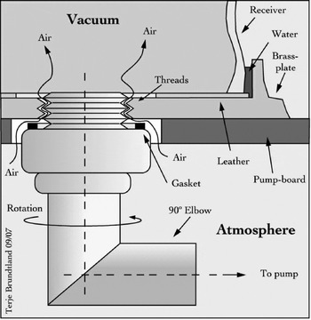
And when the experiment is over, and you would let the External Air return again into the Receiver in order to take off the Engine, you need only unscrew a little the Elbow above-mentioned, by turning the Air pump about from Left-hand towards the Right, as far as liberty allows, and then the Air will easily insinuate it self between the Joints of the Screw.Footnote 84
Hauksbee's technique was very elegant. By moving the pump barrel horizontally to the right, the elbow to which the pump was attached would be unscrewed a little from the brass plate. This would let air pass over the gasket and seep into the chamber through the opening created between the threads of the brass plate and the matching threads in the elbow. An illustration explaining these details is given in Figure 6.
The air-inlet function. Air is deliberately let into the receiver along the screw threads by turning the barrel to the right (left-hand threads). Compare Figure 5. Drawing by the author.

He could therefore easily control the quantity of air leaking in by adjusting the horizontal position of the barrel. The amount was dependent on how far the elbow was unscrewed from the brass plate. Any physical obstruction limiting the horizontal movement of the barrel would limit the flow of air into the receiver. The phrase ‘as far as liberty allows’ must therefore have been written with physical obstructions to the barrel in mind, such as the edge of the table if the pump assembly were fastened to a table, or a wall if it were mounted in a window frame. Stopping the air-inlet process was performed simply by turning the barrel towards the left until the elbow was fully tightened into the brass plate. This procedure was much more manageable than Boyle's. Small movements of the barrel's outer end would produce minute variations in the opening between the threads. It would not, as in Boyle's stopcock, open abruptly with a small movement of the vane but would open slowly and gradually as the barrel was turned, allowing the operator to fill the evacuated receiver with air carefully and in a controlled manner.
Pressure control
The air-inlet function, combined with easy pumping and convenient pressure monitoring, and the absence of manually operated stopcocks, made Hauksbee's air-pump into a much more versatile instrument than earlier models. It enabled a practice where the operator could perform series of experiments at a specific air pressure in the receiver, as well as experiments where controlled variations of the pressure were the aim. Air is an elastic substance that needs time to leave the receiver. To know exactly when to stop pumping in order to achieve a proposed height of mercury would have been difficult. If the reading stabilized at a lower value (pressure too high), the operator could carefully draw the plunger outwards until the right mark was reached. If, however, it stabilized at a higher reading (lower pressure) than desired, the operator could simply let air into the receiver by moving the barrel carefully to the right, watching the mercury column sink, and close the receiver just when the right level was reached. A description of such a practice, where systematic tests were made under series of different air pressures, is found, for example, in an article by William Derham (1657–1735) on the behaviour of pendulum clocks in vacuum, an experiment undertaken in late 1704 with Hauksbee's single-barrelled pump.Footnote 85
The final stage
By searching for the sources of Hauksbee's air-pumps, it has become evident that he had developed the single-barrelled pump beyond the construction found in Harris's Lexicon (Figure 2). Here the pump was portrayed as an assembly of different parts: the receiver, the barrel and the barometer, all fastened to a receiver-plate that in turn was fixed by screws to a table. In contrast, Hauksbee's well-known double-barrelled pump was a separate self-standing construction with four legs, holding the receiver, pump-barrels and barometer (Figure 1).
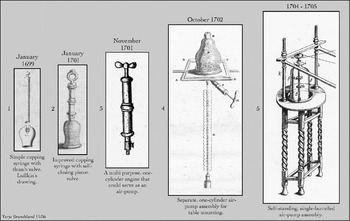
However, a model that can be said to represent the link between these two constructions is described in an article in the Philosophical Transactions for December 1705, concerning experiments on the attrition of different bodies in a vacuum.Footnote 86 Even though the accompanying illustration depicts neither a pump-barrel nor a barometer (they must have been left out for simplicity's sake), the actual structure is described as a working pump with a barometer. It resembled the profile of the stand for the double-barrelled air-pump, though it was simpler. Most of the advantages later to be found in the classical model were present in this arrangement: all the crucial components were combined in one unit, the barometer was better protected from breakage by the four legs and the device was transportable. This must have been the fifth and the last development stage before Hauksbee was to make the classic double-barrelled pump (see Figure 7).
Francis Hauksbee's path to the air-pump. The five stages of the single-barrelled air-pump (1699–1705). Compare with Figure 1. 1. Luffkin, Philosophical Transactions, 1699; 2. Harris, Lexicon Technicum, 1704; 3. Hauksbee, Philosophical Transactions, 1704; 4. Harris, Lexicon Technicum, 1704; 5. Hauksbee, Philosophical Transactions, 1705. Compiled by the author.

From medicine to natural philosophy: the new generation
If Robert Boyle's pumps can be considered the first generation of English air-pumps, Hauksbee's belong to the second. Likewise, if Leviathan and the Air-Pump can be said to represent a first chapter in the history of the English air-pump, this article provides material for an introduction to the next, even if the characters of these two accounts are rather different. While Shapin and Schaffer focused on philosophical, sociological and political issues concerning Boyle's first and second air-pumps, I have concentrated on the technical development of Hauksbee's first air-pump. Little work concerning air-pumps took place in England between the period of Boyle and Papin and that of Hauksbee.Footnote 87
The first evidence of a two-barrelled air-pump by Hauksbee is found in a newspaper announcement of 5 May 1705.Footnote 88 The pump he presented to the Royal Society on 15 December 1703 could not therefore have been this model, a question hitherto taken for granted by every modern historian. It was the simpler version described above that was used and it was this pump that received so many appreciative comments from Hauksbee's contemporaries: ‘the best air-pump I ever have seen’ (Harris),Footnote 89 ‘his Air-Pumps exceed others in the Ease of being pumped’ (Derham),Footnote 90 ‘the improved one’ (James Hodgson, 1672–1755).Footnote 91 Based on the belief that these appraisals reflect judgements of the double-barrelled pump and given the lack of information on Hauksbee's activities prior to December 1703, modern commentators have until now faced problems explaining the qualities and the sudden appearance of this particular air-pump. However, the single-barrelled pump came first, in October 1702. Furthermore, contacts between Hauksbee and the Royal Society must have been established even before then.
Not from obscurity
How was contact between Hauksbee and the Royal Society first established? His engagement as a weekly demonstrator has normally been seen in connection with Isaac Newton's initiative to restore the society after a period of decline. His introductory performance in fact took place at the first meeting that Newton led as newly elected president. Together with the fact that Hauksbee used an air-pump that particular evening, this has prompted modern commentators to look solely for possible connections with other experimental philosophers such as Boyle, Hooke and Papin. We may never know exactly when and how Hauksbee was invited to the Royal Society. His engagement may well have been part of Newton's new programme, but I judge it obvious that he must have caught Fellows' attention long before his entry and without Newton's necessary involvement. Hauksbee was a fervent advertiser of cupping utensils and air-pumps in the London newspapers before December 1703. After examination of more than a thousand copies, no evidence has come to light that others offered such commodities to the public. During certain periods Hauksbee advertised rather regularly; we might expect that the Fellows of the Royal Society would thus have learnt about him and his products. In one advertisement Hauksbee claimed that his cupping utensils were well known and appreciated by physicians and surgeons.Footnote 92 In another he stated that his method was ‘practiced by several eminent Surgeons of this City’.Footnote 93 From the new evidence about Hauksbee's production of cupping and anatomical instruments presented above and the fact that several of the members of the Royal Society were apothecaries, physicians and surgeons, I find it most probable that some Fellows were among the consumers of his devices.Footnote 94 The first contacts could thus have been made at an early stage, even before air-pumps became standard commodities. One possible candidate for such an encounter would be the surgeon, anatomist and writer William Cowper, who, for example, used anatomical injectors.Footnote 95 A meeting between Hauksbee and a member of the society had definitely taken place by the end of 1702, when John Harris visited Hauksbee's shop and saw a large ‘acute’ barometer.Footnote 96 The relevance of cupping and practical anatomy for these men also becomes clear from the Royal Society's Journal Book: it records that on his second meeting there, Hauksbee demonstrated cupping utensils and anatomical blowpipes, both equipped with valves so that the air ‘cannot return’.Footnote 97
Hauksbee must have been a public figure in London in this period. One can no longer say that he ‘emerged from obscurity’, as Henry Guerlac assumed. However, the most important issue is not how he became known, nor when he was first in contact with the Royal Society. What counts more is that in this early period Hauksbee must have achieved competence, experience and reputation as an outstanding instrument-maker, an achievement that would be extremely fruitful in his later activities in experimental philosophy.
Technology transfer
The history of the English air-pump is the history of an instrument travelling from natural philosophy to popular medicine and back again. The pump started as a philosophical instrument with Guericke and Boyle in the seventeenth century. Hauksbee applied the idea of air-pumps in his commercial cupping utensils, improved and refined the technology, then used it in turn for the new generation of air-pumps. These were instruments made for sale and intended for a society with growing interest in natural philosophy.
The state of the public attitude to natural philosophy in the early eighteenth century was different from that experienced by Robert Boyle. The concept and application of cupping and blood-letting played a role in this change. That is, cupping did not only serve as a model for Hauksbee's air-pump. The physical effects of this form of treatment, with which many must have been familiar, were indeed suitable as starting points for discussing basic natural philosophical concepts of the atmosphere and of air in general. This becomes especially clear from public lecture syllabi, many given by Hauksbee. Among the topics taught was pneumatics, that branch of natural philosophy concerned with the weight, pressure and spring of the air, and the phenomenon of ‘air in the flesh’.Footnote 98
The lecturers used a variety of methods to make air's properties comprehensible to audiences, including the use of syringes and cupping-glasses. Such devices were used to convince the public that suction was caused by external air pressure and were applied when explaining that effects previously attributed to the horror vacui were in fact due to the pressure of the air.Footnote 99 Experiments were performed to make the air's pressure ‘sensible to the touch’ by letting the hand be sucked onto a cylinder rim by vacuum.Footnote 100 In principle this was the same effect that patients would experience in Hauksbee's cupping method. Such phenomena were again used to explain why cupping-glasses could stick to human skin.
Another issue, also related to the human body, was the phenomenon of ‘air in the flesh’. A seventeenth-century query asked why, if the atmosphere were able to exert a pressure of several tons on the human body, did this force not crush the body?Footnote 101 The answer provided was simply that air in the body's pores exerted a similar outward pressure and maintained equilibrium.Footnote 102 This phenomenon now became visible in public lectures and explained why bubbles were extracted from a piece of raw flesh submerged in a water tank within an evacuated receiver, showing that air really was trapped inside it.Footnote 103 Similarly, it was shown that there was air in various fluids such as blood. These phenomena are closely related to cupping, as the expanding ‘air in the flesh’ causes the swelling of the skin as well as the flow of blood into the cupping-glass. The connection between cupping utensils and air-pumps and between the body and natural philosophy becomes clear. Cupping technology was transferred to the air-pump; air-pumps and cupping utensils were used to explain both the natural phenomena of air and also the effects experienced by the body during cupping.
Pumps for sale
When did the English air-pump shift from problematic prototype to stabilized and common commodity? In the 1670s, so Shapin and Schaffer write, ‘the air-pump gradually changed from being the restricted property of a few privileged individuals to becoming commercially available articles’.Footnote 104 They underpin this view by showing the status that the air-pump had achieved among natural philosophers in Holland and in France and that a market for such instruments had developed, a process in which Papin is given a crucial role. The pump is described as ‘an unproblematic resource and no longer an assemblage of controversial theoretical and practical components’. Further, they make a connection between the advance of the air-pump on the Continent and its development in England by showing that Papin had built the double-barrelled pump while working for Boyle. Similar claims are also expressed by the editors of Boyle's Works, who write that Papin's double-barrelled pump superseded the previous ones and that air-pumps had generally become cheaper and more widely available.Footnote 105
An impression gained from these arguments is that the air-pump had also become black-boxed and commercialized in England in this period. However, there are few signs of Boyle or Papin's pump models being replicated or refined into commercial products. Further, it seems that not many air-pump experiments were performed in England at all between the period of Boyle and Papin and that of Hauksbee. The Philosophical Transactions, for example, carry no accounts of specific air-pump experiments undertaken in England between 1675 (Boyle)Footnote 106 and 1704 (Hauksbee).Footnote 107 The importance of the air-pump as a philosophical instrument was clearly acknowledged in the period, but few experiments were performed and then reported.Footnote 108 I therefore argue that developments similar to those which took place in Holland and France did not happen in England until thirty years later, but did so then with Francis Hauksbee in command. The first commercial English air-pump was thus Hauksbee's single-barrelled model of 1702, stemming from cupping utensils, and contrived several years before the celebrated double-barrelled one was in prospect.
Conclusion
Hauksbee did not emerge from obscurity, nor can he be described as a student of Robert Boyle. His double-barrelled air-pump was not simply a successor to that of Papin, and he was a public figure known to the Royal Society years before Newton took charge. The present study has revealed that his celebrated double-barrelled air-pump was realized through a development of several versions of cupping utensils, anatomical syringes, a multipurpose device and a single-barrelled air-pump. Cupping, blood-letting and practical anatomy (as well as the practice of newspaper advertising) thus have an important role in the history of the air-pump. The confusion described by Wilson in 1849 and fuelled by speculations made in the 1950s is now considerably reduced. However, there is still a series of issues to be studied concerning Hauksbee and his air-pumps. Questions about the role of the air-pump in public lectures, about the air-pump as a tool in research and manufacturing and as a status symbol among the upper classes have yet to be answered.